Embed Size (px)
Citation preview

3
1
Overview of Triboelectric NanogeneratorsXiaosheng Zhang
University of Electronic Science and Technology of China, School of Electronic Science and Engineering,No. 2006, Xiyuan Ave, West Hi-Tech Zone, Chengdu 611731, P.R. China
Ambient energy is abundant in the environment and takes various forms, suchas solar irradiation [1], thermal gradient [2], mechanical deformation [3], andso on, which can be converted into electricity using ambient energy-harvestingtechniques [4]. The approach to harvesting energy from the environment isone of the ideal solutions to respond to the energy demands of distributedautonomous microsystems, which should be sustainable, renewable, and ofhigh performance [4]. Ambient energy-harvesting technology provides anattractive future vision to realize fully integrated self-powered microsystemsthat overcome the drawbacks of batteries, which currently need to be frequentlyreplaced, or of laying out long wires for power supply [5]. In 2012, a new ambientenergy-harvesting mechanism named triboelectric nanogenerator (TENG)was developed by combining the triboelectrification effect and electrostaticinduction [6, 7]. This novel technology has proved to be a robust power sourceto directly power commercial electronics and even regular light bulbs [7]. Therehas been a remarkable growth of TENG research in the past years due to itsunique properties, including high-output performance, cleanness, sustainability,etc. [8, 9]. Mechanical energy from sources such as wind, raindrops, and oceanwaves, as well as body motions can be efficiently converted to electric powerusing TENGs. Therefore, this chapter summarizes the current progress ofmicroenergy technologies and then introduces an overview of TENG.
1.1 Energy Crisis of Microsystems
In the past half century, as the benefit of the rapid development of electronicscience and technology, human society gradually changed to automation,both intelligent and digitization, and various electronic devices have becomepart of our life and are distributed everywhere. The featured size of modernelectronic devices becomes smaller year by year down to the millimeter, andeven to micrometer levels, which induces a continuous decrease in powerconsumption down to milliwatts and even to microwatts. Consequently, the
Flexible and Stretchable Triboelectric Nanogenerator Devices: Toward Self-powered Systems,First Edition. Edited by Mengdi Han, Xiaosheng Zhang, and Haixia Zhang.© 2019 Wiley-VCH Verlag GmbH & Co. KGaA. Published 2019 by Wiley-VCH Verlag GmbH & Co. KGaA.

4 1 Overview of Triboelectric Nanogenerators
great reforms in small-size and low-power consumption promote the integrationof multifunctional electronic devices to realize microsystems.
Microsystems experienced a blooming development in the past decades result-ing from their unique features, i.e. portable, smart, and miniature. However,the further development of microsystems suffered several critical challenges,especially the exploration of appropriate power sources. At present, batteries arestill the first option, especially some of the flexible batteries, but the problemsof sustainability and pollution caused by batteries cannot be ignored. In themeantime, distributed autonomous microsystems also have some new energydemands such as sustainability, renewability, high performance, and evenflexibility or stretchability.
As an essential example of microsystems, Internet of things (IoT) is expectedto play an important role in economic and social development of the next gen-eration, as shown in Figure 1.1. Thus, IoT is taken as an example to describe theenergy crisis of microsystems [10].
In principle, an IoT system is composed of three main parts: sensing network,interconnection network, and terminal network. The sensing network detectsthe various changes of environmental factors and transforms them as electronicsignals. Subsequently, the electronic signals are transferred to the interconnec-tion network and treated to form control signals. Eventually, these control signalsare delivered to the terminal network to drive functional electronic devicesto respond to the corresponding changes. Therefore, the sensing networkserving as the interface media between environment and client is the essentialcomponent of the IoT. The sensing network consists of trillions of sensors,which are widely distributed in the environment, especially in autonomousstates.
Consequently, exploring an appropriate power approach for the sensingnetwork is an urgent issue for the rapid development of IoT. Micro energy
Autonomousremote and operation
Multiplefunctions
Harshenvironment
Sensingnetwork
Interconnection
network
Internet of things(IoT)
Terminalnetwork
High-performance Sustainability
Maintains free Self-powered operation
Microenergy source
Figure 1.1 Schematic view of the Internet of things (IoT) and its power supply requirements.It is of great significance for the development of IoT to realize the appropriate microenergysource that fits the unique requirements.

1.2 Microenergy Technologies 5
sources harvesting energy from the ambient have been proven as one of theattractive methods. By using piezoelectric, thermoelectric, photovoltaic effects,etc., microenergy harvesters can accumulate energy in various forms andconvert them to electricity to power miniature devices and systems. There microenergy-harvesting technologies are clean, sustainable, and low-cost. Moreover,it provides the feasibility to integrate functional electronic components withthese microenergy sources.
1.2 Microenergy Technologies
A promising way to satisfy the energy demands of low-power-consumptionmicrosystems is to collect energy from the living environment. Because thefeatured size and the electric output are at milliscale or even microscale levels,the ambient energy-harvesting technologies are also named as microenergytechnologies. They possess attractive advantages to realize fully integrated,self-powered devices which do not need replacement of batteries or laying outlong wires for charging.
Previous research work has exploited several techniques using different mech-anisms, such as photoelectric conversion, piezoelectric effect, thermoelectriceffect, biochemical effect, etc. These techniques can be used to collect variousforms of environmental energy such as light, mechanical change, temperaturedifference, variation of electromagnetic field, etc.
Herein, we summarize and compare five essential technologies for ambientenergy-harvesting in Figure 1.2 and Table 1.1. Since the specific application
100 WPT
MC
N/A
100
90
80
70
Energ
y c
onve
rsio
n e
ffic
iency*
(%)
60
50
40
30
20
10
0
90
80
70
60
50
401 cm
30
20
Pow
er
density*
(mW
/cm
2)
10
0
Photovoltaic Thermoelectric Electromagnetic Piezoelectric Triboelectric
Figure 1.2 Summary of technical progress of five promising methods for harvesting energyfrom the environment. Source: Reproduced with permission from Zhang et al. [4].Copyright 2018, Elsevier.

Tab
le1.
1C
omp
aris
onof
five
tech
nolo
gies
fora
mb
ient
ener
gyha
rves
ting.
Typ
eSc
hem
atic
view
Volt
age
(V)
Cur
ren
t(A
)
Pow
erd
ensi
ty(m
W/c
m2
)Effi
cien
cy(%
)Pr
osve
rsus
con
s
Phot
ovol
taic
(PV
)Illu
min
ation
0.5–
0.9
100–
500
5–30
0.3–
46H
igh
outp
utpo
wer
,con
tinuo
usD
Cou
tput
,goo
dba
sisof
indu
stria
lfa
bric
atio
nFo
rthe
flexi
ble
orga
nic
sola
rcel
l,th
eco
nver
sion
effici
ency
isst
illve
rylo
w,on
lyw
orks
unde
rlig
htTh
erm
oele
ctric
(ThE)
Heating
0.1–
15–
300.
01–3
0.1–
25Su
stai
nabl
yw
orki
ngas
aD
Cpo
wer
sour
ce,e
asy
tosc
ale
dow
n,no
mov
ing
com
pone
ntLo
wco
nver
sion
effici
ency
,low
outp
utpe
rfor
man
ce,l
arge
tem
pera
ture
diffe
renc
eEl
ectr
omag
netic
(EM
)E
lectr
om
agnetic
0.1–
10N
/AN
/A5–
90H
igh
conv
ersio
neffi
cien
cy,h
igh
curr
entw
ithlo
wvo
ltage
,res
istiv
eim
peda
nce
Forw
irele
sspo
wer
tran
smiss
ion:
shor
tra
nge,
wor
king
atce
rtai
nfr
eque
ncy;
Form
agne
tmov
ing:
heav
yw
eigh
tand
big
size,
com
plex
ity
Piez
oele
ctric
Pre
ssure
1–20
00.
01–1
00.
001–
300.
01–2
1H
ighl
yse
nsiti
veto
exte
rnal
exci
tatio
n,ea
sily
inte
grat
esan
dm
inia
turiz
esin
mic
ro-/
nano
scal
eLo
wco
nver
sion
effici
ency
,low
outp
utpe
rfor
man
ce,p
ulse
outp
ut,h
igh
impe
danc
eTr
iboe
lect
ric(T
rE)
Fri
ction
3–15
0010
–200
00.
1–10
010
–85
Hig
hou
tput
and
ener
gyco
nver
sion
effici
ency
,no
mat
eria
lslim
itatio
n,re
mar
kabl
efle
xibi
lity
Pulse
outp
ut,h
igh
impe
danc
e,fr
ictio
nda
mag
e
Sour
ce:R
epro
duce
dw
ithpe
rmiss
ion
from
Zhan
get
al.[
4].C
opyr
ight
2018
,Else
vier
.

1.2 Microenergy Technologies 7
area is limited for self-powered flexible microsystems, only flexible or wearableconfigurations of these five technologies are emphasized.
1.2.1 Photovoltaic Effect
The solar cell is one of most popular power sources based on photovoltaic effect.The basic law of photovoltaic effect is that electrons overcome the potential bar-rier and are excited to a higher energy state by absorbed lights. The frequencyof light must exceed a certain range in order to possess sufficient energy to over-come the potential barrier for excitation, and then the separation of charges leadsto the establishment of an electric potential [4, 11].
So far, solar cells can be divided into five main categories, including multi-junction cells, single-junction GaAs, crystalline silicon cells, thin-film technolo-gies, and emerging others [12]. The first three types possess better performance,with the energy conversion efficiency (ECE) ranging from 21.2% to 46%, andsilicon-based solar cells dominate the commercial market [12]. Nevertheless,because of fragile and nonflexible characterization, it is difficult to apply them inwearable microsystems.
By contrast, the latter two classifications show good flexibility by fabricatingspecific functional materials on polymeric substrates, but their ECEs are still at arelatively low level, with copper indium gallium selenide (CIGS), perovskite, anddye-sensitized solar cells reaching the highest values of 23.3%, 22.1%, and 11.9%,respectively [12].
1.2.2 Thermoelectric Effect
As is known, the human body itself is a perfect energy source to provide thermaldissipation and physical movement [13, 14], which is regarded as an attractivesolution to satisfy the power demand of wearable electronics. The thermoelectriceffect is employed to transform the energy generated by the thermal dissipationof the human body to electricity. When a temperature difference is applied tothermoelectric devices, an electrical potential that can drive the flow of electronsin the circuit loop to generate the electricity will be established, which is namedthe Peltier–Seebeck effect [4, 15].
Thermoelectric generators can be classified into inorganic and organic. Inor-ganic thermoelectric generators are made from inorganic materials, such as sev-eral alloys and intermetallic compounds based on elements like Bi, Te, Sb, Pb,etc., which are, as a matter of fact, toxic [16].
Organic thermoelectric generators are usually manufactured using conductivepolymers (i.e. conjugated polymers and certain coordination polymers) and smallmolecules (i.e. charge-transfer complexes and molecular semiconductors) [15].They have attracted much attention because of the properties of light weight andoutstanding flexibility. However, the ECE needs to be strengthened, which is stillat a relatively low level of less than 25%. The ECE of the thermoelectric gener-ator is defined as a function of the figure of merit (ZT), average working tem-perature, and the temperature difference between the hot and cold ends. Thus,compared with ECE, the figure of merit, i.e. ZT = S2
𝜎T/k, is more important
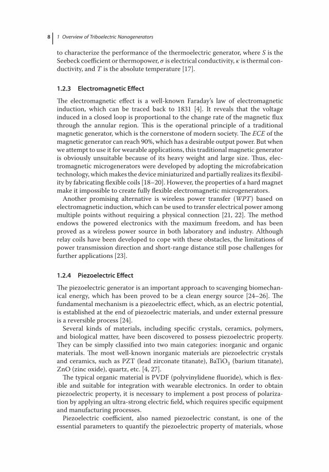
8 1 Overview of Triboelectric Nanogenerators
to characterize the performance of the thermoelectric generator, where S is theSeebeck coefficient or thermopower, 𝜎 is electrical conductivity, 𝜅 is thermal con-ductivity, and T is the absolute temperature [17].
1.2.3 Electromagnetic Effect
The electromagnetic effect is a well-known Faraday’s law of electromagneticinduction, which can be traced back to 1831 [4]. It reveals that the voltageinduced in a closed loop is proportional to the change rate of the magnetic fluxthrough the annular region. This is the operational principle of a traditionalmagnetic generator, which is the cornerstone of modern society. The ECE of themagnetic generator can reach 90%, which has a desirable output power. But whenwe attempt to use it for wearable applications, this traditional magnetic generatoris obviously unsuitable because of its heavy weight and large size. Thus, elec-tromagnetic microgenerators were developed by adopting the microfabricationtechnology, which makes the device miniaturized and partially realizes its flexibil-ity by fabricating flexible coils [18–20]. However, the properties of a hard magnetmake it impossible to create fully flexible electromagnetic microgenerators.
Another promising alternative is wireless power transfer (WPT) based onelectromagnetic induction, which can be used to transfer electrical power amongmultiple points without requiring a physical connection [21, 22]. The methodendows the powered electronics with the maximum freedom, and has beenproved as a wireless power source in both laboratory and industry. Althoughrelay coils have been developed to cope with these obstacles, the limitations ofpower transmission direction and short-range distance still pose challenges forfurther applications [23].
1.2.4 Piezoelectric Effect
The piezoelectric generator is an important approach to scavenging biomechan-ical energy, which has been proved to be a clean energy source [24–26]. Thefundamental mechanism is a piezoelectric effect, which, as an electric potential,is established at the end of piezoelectric materials, and under external pressureis a reversible process [24].
Several kinds of materials, including specific crystals, ceramics, polymers,and biological matter, have been discovered to possess piezoelectric property.They can be simply classified into two main categories: inorganic and organicmaterials. The most well-known inorganic materials are piezoelectric crystalsand ceramics, such as PZT (lead zirconate titanate), BaTiO3 (barium titanate),ZnO (zinc oxide), quartz, etc. [4, 27].
The typical organic material is PVDF (polyvinylidene fluoride), which is flex-ible and suitable for integration with wearable electronics. In order to obtainpiezoelectric property, it is necessary to implement a post process of polariza-tion by applying an ultra-strong electric field, which requires specific equipmentand manufacturing processes.
Piezoelectric coefficient, also named piezoelectric constant, is one of theessential parameters to quantify the piezoelectric property of materials, whose

1.3 Triboelectric Nanogenerators 9
variation ranges from tens to thousands. Therefore, the performance of apiezoelectric generator has a direct relation with the piezoelectric propertyof the selected material. The remarkable linear characteristic between inputpressure stimulation and output electric signal makes piezoelectric generatorssuitable to play the part of self-powered transducers [5]. It deserves to bementioned that piezoelectric nanogenerators (PENGs) based on ZnO nanowireshave developed vigorously in the past decades [28].
1.3 Triboelectric Nanogenerators
The traditional techniques proposed for microenergy sources are still hinderedmore or less by the following limitations, such as low output performance, strictenvironmental requirement, and low conversion efficiency. In 2012, a novel ambi-ent energy-harvesting technology was developed. Named TENG, it combinestriboelectrification effect and electrostatic induction [4, 6].
The charge generated at the friction interface of two different materials (i.e. thetriboelectric pair) is defined as the triboelectrification effect. Although the obser-vation and description of the electrification effect can be traced back more than3000 years ago, the question is how to accumulate charges, generate electricity,and minimize the size in an efficient way.
By setting two electrodes on the back surface of a triboelectric couple, electrifi-cation effect and electrostatic induction are combined for effective power conver-sion [4, 6]. In the past five years, TENGs have aroused widespread interest due toexcellent properties of high-output performance, low cost, being maintenance-free, sustainability, and green power performance. In order to strengthen andextend the capabilities of TENGs, a variety of techniques have been developed,and the power density has reached tens of mW/cm2 level [9]. Furthermore, themaximum power conversion efficiency was achieved at 85% [29].
Since the electrification effect exists between nearly all of the two differentmaterials used, this technique has great tolerance with material selection, andplenty of polymers and organic materials can be selected to achieve flexibleand even stretchable devices. Besides, micro-/nanopatterned surfaces areusually adopted to maximize the effective friction area and enhance the outputperformance, and TENGs serve to emphasize it [30–34].
1.3.1 Principle of Triboelectric Nanogenerators
The original prototype of TENG had a triboelectric pair made of two differentmaterials and two electrodes placed at the back. The operation principle can bedescribed using contact-separation-mode TENG, as shown in Figure. 1.3.
Firstly, the whole TENG is electrically neutral and the triboelectric pair mate-rials are separate. Under an action of external force, the pair makes contact andgenerates friction, and then surface charges are generated at the friction interface.Because of the difference in capabilities of losing or capturing electrons duringelectrification, one material of the triboelectric pair loses electrons and showspositive potential, while another captures electrons and shows negative potential.

10 1 Overview of Triboelectric Nanogenerators
Electrode 1
Triboelectric material 1
Triboelectric material 2
Electrode 2(a)
(b) (c)
(d)(e)
–I
Approaching Separating
Figure 1.3 The working principle of contact-separation-mode triboelectric nanogenerators(TENGs). (a) In the beginning, the triboelectric pair made of triboelectric materials 1 and 2 areseparated, and the whole device shows an electrically neutral state. (b) When a compressiveforce is applied, the top structures will move toward the bottom structures and have a frictionwith each other. Due to the phenomenon of triboelectrification effect, positive and negativecharges of equal amount will be generated on the surfaces of triboelectric pair, respectively.(b–d) When the compressive force is removed, the triboelectric pair will separate from eachother as a result of the mechanical recovery force. And then, an internal electric potential isestablished, which changes accordingly as the distance of the triboelectric pair increases anddecreases. Consequently, due to the electrostatic induction, opposite charges are generatedon the back electrodes, and a current (I) can be detected in the loop resulting from the chargesflowing from one electrode to the other. When the triboelectric pair works cyclically, anelectric output power will be generated continuously. Source: Reproduced with permissionfrom Zhang et al. [4]. Copyright 2018, Elsevier.
In principle, the total charge amounts on the surface of the triboelectric pair areequal.
Secondly, after removing the external force, the triboelectric pair separatesand an internal potential is established owing to the electrostatic induction.During the separation process, this internal potential will drive charges to flowfrom one electrode to the other through the connection loop to make the changeof electrical potential balanced. And then, a positive current is formed, namely,electricity is generated. This is named the process of separating.

1.3 Triboelectric Nanogenerators 11
Thirdly, when applying an external force to the TENG again, the triboelectricpair moves toward each other, which will cause charges to flow back due to theopposite change of electrical potential. Thus, a negative current is formed, andthis process is named approaching.
Finally, the triboelectric pair makes contact again and there is friction, and thena new cycle begins. Thus, when TENG repeats this separating–approaching cycle,it produces a periodical electric output with positive and negative parts.
The output performances of CS-mode TENGs were not so advantageous and itremained at a low level of several or tens of volts at the beginning. Subsequently,an arch-shaped geometry design was introduced, whereby surface roughness wasincreased. It significantly expanded the output voltages and power densities ofCS-mode TENGs to hundreds of volts and several mW/cm2 [9].
The fundamental mechanism for enhancing output by increasing surfaceroughness is to maximize the effect friction area, and more surface chargescan therefore be generated [30]. As for the arch-shaped optimization, the basicrule of output enhancement can be roughly described by introducing a capaci-tance equivalent mode [35]. Assuming the surface charges (Q) are constant, thepotential difference (U = Q/C) between two electrodes increases sharply whenthe capacitance (C) decreases sharply due to the stronger mechanical restoringforce from the arch-shaped design. The CS-mode TENGs have the advantageof high output voltage, and their simple geometric structure makes for easyutilization, for instance, to convert most mechanical energies, such as pressing,impacting, bending, shaking, vibration, etc. However, using them for harvestingmechanically rotational energy is hard to achieve, and the frequency effect studyalso figured out that the CS-mode TENGs are not suitable for high-frequencyapplications [30].
1.3.2 Key Factor: Triboelectric Series
TENG development is based on the progress of materials. As described inSection 1.3.1, the key of electrification is the ability difference of losing or cap-turing electrons between the triboelectric pairs. Basically, if the ability relativedifference of triboelectric pairs becomes larger, then the output performance offabricated TENG becomes better as a result of the enhancement of generatedsurface charges. A table of triboelectric series, which qualitatively points outthese ability differences, was established, and is summarized in Table 1.2.
The triboelectric series table is essential for constructing high-performanceTENGs, since it quantitatively figures out the relative ability difference of los-ing/capturing electrons during the triboelectrification effect [36]. If the tribo-electric pairs have a larger difference in this table, it means that it is easier forelectrons to transfer from one to the other during the triboelectrification effect.
1.3.3 Material Progress of Triboelectric Nanogenerators
In the past few years, great progress was made in different triboelectric pairs forTENGs, as listed in Table 1.3. In this table, the materials in the left column, high-lighted in yellow, indicate that they are easy to lose electrons and show positive

12 1 Overview of Triboelectric Nanogenerators
Table 1.2 Triboelectric series of different materials.
Triboelectric series
No. Materials No. Materials No. Materials
POSI
TIV
E
1 Aniline–formolresin
17 Styrene-acrylonitrilecopolymer
33 Polyacrylonitrile
2 Polyformaldehyde1.3–1.4
18 Styrene-butadienecopolymer
34 Acrylonitrile-vinyl chloride
3 Ethylcellulose 19 Wood 35 Polybisphenol carbonate4 Polyamide 11 20 Hard rubber 36 Polychloroether5 Polyamide 6-6 21 Acetate, Rayon 37 Polyvinylidene chloride
(Saran)6 Melanimeformol 22 Polymethyl
methacrylate (Lucite)38 Poly(2,6-dimethyl
polyphenyleneoxide)7 Wool, knitted 23 Polyvinyl alcohol 39 Polystyrene8 Silk, woven 24 Polyester (Dacron)
(PET)40 Polyethylene
9 Polyethyleneglycol succinate
25 Polyisobutylene 41 Polypropylene
10 Cellulose 26 Polyurethane flexiblesponge
42 Polydiphenyl propanecarbonate
11 Cellulose acetate 27 Polyethyleneterephthalate
43 Polyimide (Kapton)
12 Polyethyleneglycol adipate
28 Polyvinyl butyral 44 Polyethylene terephthalate
13 Polydiallylphthalate
29 Formo-phenolique,hardened
45 Polyvinyl chloride (PVC)
NEG
ATIV
E14 Cellulose(regenerated)sponge
30 Polychlorobutadience 46 Polytrifluorochloroethylene
15 Cotton, woven 31 Butadiene-acrylonitrilecopolymer
47 Polytetrafluoroethylene(Teflon)
16 Polyurethaneelastomer
32 Natural rubber
Source: Reproduced with permission from Zhang et al. [4]. Copyright 2018, Elsevier.
potential. The materials in the top row, highlighted in blue, indicate that they arerelatively easy to capture electrons and show negative potential.
Currently, the widely used materials are PTFE (polytetrafluoroethylene),PDMS (polydimethylsiloxane), PI (polyimide), and FEP (fluorinated ethylenepropylene), composed of 14, 11, 11, and 8 triboelectric pairs, respectively, asshown in Table 1.3. The main reason is that they occupy the bottom-tier levelsin the triboelectric series, which leads to their outstanding abilities of capturingelectrons during the electrification effect. The sequence of electron-capturingability is listed as PTFE>PDMS>PI [7], and FEP is almost like PTFE with littledifference in molecular structure.
Among known materials, PTFE, also known as Teflon, has the strongest abilityto capture electrons, and possesses ultrastable chemical and physical properties.

Tab
le1.
3Th
eco
nfigu
ratio
nof
trib
oele
ctric
pai
rs(u
pto
Oct
ober
2017
).
Trib
oele
ctri
c p
airs
PTFE
PDM
SPo
lyim
ide
FEP
Pary
len
ePV
CRu
bb
erPF
AG
rap
hen
eEp
oxy
Poly
olef
inPV
DF
Poly
este
rG
roun
dPE
Poly
amid
ePU
PET
Alg
inat
e
sod
ium
Hum
an
skin
Silic
one
PP
30.710290 .5102
60.410220.4102
10.31025 0.5 10 2
30.410230. 61 02
90.310250.3 102
11 .21 024 0.3102
lA
lateM
Ag
2012
.12
2013
.08
90.310240.7102
11.410240.3102
uA Cu
2013
.06
2013
.08
2014
.03
2015
.06
2015
.03
2015
.03
Ni
2016
.08
2016
.01
2015
.03
Stee
l20
14.0
320
15.01
Oxi
deIT
O20
16.05
2013
.02
TiO
220
13.04
2014
.01
Al 2O
320
15.01
SiO
220
14.05
2013
.07
2014
.04
2013
.11
Gra
phen
eox
ide
2017
.01
60 .610 210.2102
50.21 02650 .310 2
T EPre
myloPPM
MA
2012
.08
Nyl
on20
13.04
2015
.11
2014
.07
PU20
15.05
PPy
2015
.12
Ure
than
e20
17.01
PVA
2016
.11
EVA
2014
.12
Biod
e-gr
adab
lePo
lym
er20
16.0
3
s reh tO
7 0.4 10 2
9 0.610 211.610 2
2013
.08
2014
.05
2 1.3 10 220
16.0
6
2016
.09
2 1.5 102
2 0.5 10270. 6102
40. 41 021 1 .5 10 2
10. 310 2
2014
.04
2017
.01 50. 41 02
xe taL Car
bon
Black
CNT
esolul leC
nio rb fikli S Pape
rH
uman d iuqiL
12
33
1141
sriaplato T The
date
in th
e fo
rm re
pres
ents
the
first
tim
e th
is tr
iboe
lect
ric p
air w
as re
port
ed in
pub
licat
ions
. The m
ater
ials
in th
e le
ft an
d th
e rig
ht co
lum
nsm
ean
the
posit
ive
and
nega
tive
part
sin
each
trib
oele
ctric
EVA
:ethyl
ene-vi
nyla
ceta
te,P
P:po
lypr
opyl
ene,
PPy:
poly
pyrr
ole,
PU:p
olyu
reth
ane,FE
P:flu
orin
ated
ethy
lene
prop
ylen
e,PF
A: p
olyfl
uoro
alko
xy,P
VC
:polyv
inyl
chlo
ride,
ITO
:ind
ium
tinox
ide,
CNT:
carb
onna
notu
bes,
PVDF:
polyvi
nylid
ene
fluor
ide,
PDM
S: p
oly(
dim
ethy
lsilo
xane
),PM
MA
:poly(m
ethy
lmet
hacryl
ate)
,PE:
poly
ethy
lene
,PET
:polye
thyl
ene
tere
phth
alat
e,Bi
odeg
rada
ble
polym
er:
poly
(l-la
ctid
e-co
-gly
colid
e)(P
LGA
),po
ly(3
-hyd
roxy
buty
ricac
id-c
o-3-
hydr
oxyv
aler
icac
id)(
PHB/
V),
poly
(cap
rola
cton
e)(P
CL)
,poly(vi
nyl a
lcoh
ol)(
PVA
).
part
sin
each
trib
oele
ctric
pair,
resp
ectiv
ely.
Sour
ce:R
epro
duce
dw
ithpe
rmiss
ion
from
Zhan
get
al.[4]
.Cop
yrig
ht20
18,E
lsevi
er.

14 1 Overview of Triboelectric Nanogenerators
PDMS is a kind of biocompatible material which can be micro-/nanopatternedeasily using the molding cast process, and it also maintains a good stretchablecapability. PI, also known as Kapton, can be processed into elastic thin films andmade to work under high-temperature conditions.
Regarding the negative part of triboelectric pairs, materials can be classifiedinto four groups: metals, oxides, polymers, and others. Metals can work as tri-boelectric pairs and electrodes at the same time [37–39], which simplifies thestructure of TENGs. Oxide compounds are widely used, including ITO (indiumtin oxide), TiO2, Al2O3, SiO2, and graphene oxide. Among the rest, ITO exhibits aunique feature of conductivity and an outstanding property of transparency [40].Polymers are the most important type of triboelectric materials; therefore, TENGis also called organic nanogenerator, which is firstly used to collect mechanicalenergy as organic materials [7].
One of the most attractive benefits of TENG is its tolerance to the materialselection, since almost all of the two different kinds of materials are able to gen-erate the electrification effect. Therefore, as is shown in Table 1.3, there are a greatnumber of triboelectric pairs made up of different materials. However, the electri-cal performance of fabricated TENG depends on the ability difference of losing orcapturing electrons. From this point of view, the materials are expected to possessthe excellent electrical property of easily losing or capturing electrons. Exploringnovel triboelectric materials still exists as an important research topic. In addi-tion, triboelectric materials are expected to achieve excellent flexibility or evenstretchability, environmental friendliness, or even biocompatibility, which fulfillsthe demand for constructing flexible and wearable self-powered microsystems.
1.3.4 Challenges of Triboelectric Nanogenerators
So far, the rapid development of TENG is still confronted with two challenges:one is the requirement to enhance power density, and the second is to simplifythe structure to realize easier integration. Although simply enlarging the size canenhance the output power of TENG, the area power density remains constant,which is closely relevant to the fundamental mechanism of the triboelectrifica-tion effect, especially the triboelectric series that qualitatively depends on theability of the triboelectric pair to lose or capture electrons [4]. Moreover, althoughfour types of TENGs with different working principles have already been devel-oped [4], such as contact-separation mode and relative-sliding mode, integratingTENG with other components to realize fully integrated self-powered microsys-tems still requires a lot of effort.
1.4 Summary
Through the abovementioned analyses and comparisons, we can summarize thatTENGs possess much more attractive potentials and are considered as one of thepromising ambient energy-harvesting approaches. In the latter part of this book,we summarize the emerging technology of TENG which serves as an impor-tant component of self-powered flexible and wearable microsystems, including

References 15
the innovation of working principle and material selection, the functionalizationof sensing and actuating, and the future development direction of the all-in-oneconcept.
Abbreviations
CNT carbon nanotubesCS contact-separation modeECE energy conversion efficiencyEM electromagneticEVA ethylene-vinyl acetateFEP fluorinated ethylenepropyleneFS free-standing modeIoT Internet of thingsITO indium tin oxidePCL poly(caprolactone)PDMS poly(dimethylsiloxane)PE polyethylenePET polyethylene terephthalatePFA polyfluoroalkoxyPHB/V poly(3-hydroxybutyricacid-co-3-hydroxyvaleric acid)PLGA poly(l-lactide-co-glycolide)PMMA poly(methyl methacrylate)PP polypropylenePPy polypyrrolePU polyurethanePV photovoltaicPVA poly(vinyl alcohol)PVC polyvinyl chloridePVDF polyvinylidene fluoridePZT lead zirconate titanateRS relative-sliding modeSE single-electrode modeTENG triboelectric nanogeneratorThM thermoelectricWPT wireless power transfer
References
1 Lewis, N.S. (2007). Toward cost-effective solar energy use. Science 315:798–801.
2 Snyder, G.J., Lim, J.R., Huang, C.K., and Fleurial, J.P. (2003). Thermo-electric microdevice fabricated by a MEMS-like electrochemical process.Nature Materials 2: 528–531.

16 1 Overview of Triboelectric Nanogenerators
3 Lee, J.H., Lee, K.Y., Gupta, M.K. et al. (2014). Highly stretchablepiezoelectric-pyroelectric hybrid nanogenerator. Advanced Materials 26:765–769.
4 Zhang, X.S., Han, M., Kim, B. et al. (2018). All-in-one self-powered flexiblemicrosystems based on triboelectric nanogenerators. Nano Energy 47:410–426.
5 Wang, Z.L. and Wu, W.Z. (2012). Nanotechnology-enabled energy harvestingfor self-powered micro-/nanosystems. Angewandte Chemie 51: 11700–11721.
6 Fan, F.R., Tian, Z.Q., and Wang, Z.L. (2012). Flexible triboelectric generator.Nano Energy 1: 328–334.
7 Wang, Z.L. (2013). Triboelectric nanogenerators as new energy technologyfor self-powered systems and as active mechanical and chemical sensors. ACSNano 7: 9533–9557.
8 Zhang, X.S., Han, M.D., Meng, B., and Zhang, H.X. (2015). High perfor-mance triboelectric nanogenerators based on large-scale mass-fabricationtechnologies. Nano Energy 11: 304–322.
9 Wang, Z.L., Chen, J., and Lin, L. (2015). Progress in triboelectric nanogenera-tors as a new energy technology and self-powered sensors. Energy & Environ-mental Science 8: 2250–2282.
10 Zhang, X.S. (2016). Micro/nano integrated fabrication technology and itsapplications in microenergy harvesting. Springer, ISBN:978-3-662-48814-0.
11 Würfel, P. (2009). Physics of Solar Cells: From Basic Principles to New Con-cepts, 2e. Wiley. ISBN: 978-3-527-40857-3.
12 Best Research – Cell Efficiencies (2018). National Renewable Energy Labora-tory, NREL. https://www.nrel.gov/pv/assets/images/efficiency-chart.png.
13 Riemer, R. and Shapiro, A. (2011). Biomechanical energy harvesting fromhuman motion: theory, state of the art, design guidelines, and future direc-tions. Journal of Neuro Engineering and Rehabilitation 8: 22.
14 Park, J., Lee, Y., Ha, M. et al. (2016). Micro/nanostructured surfaces forself-powered and multifunctional electronic skins. Journal of MaterialsChemistry 4: 2999.
15 Zhang, X. and Zhao, L.D. (2015). Thermoelectric materials: energy conversionbetween heat and electricity. Journal of Materiomics 1: 92–105.
16 Zhang, Q., Sun, Y., Xu, W., and Zhu, D. (2014). Organic thermoelectric mate-rials: emerging green energy materials converting heat to electricity directlyand efficiently. Advanced Materials 26: 6829–6851.
17 Yang, J., Yip, H.L., and Jen, A.K.Y. (2013). Rational design of advanced ther-moelectric materials. Advanced Energy Materials 3: 549–565.
18 Sun, X., Peng, X., Zheng, Y. et al. (2014). A 3-D stacked high-Q PI-basedMEMS inductor for wireless power transmission system in bio-implantedapplications. Journal of Microelectromechanical Systems 23: 888–898.
19 Han, M., Yuan, Q., Sun, X., and Zhang, H. (2014). Design and fabrication ofintegrated magnetic MEMS energy harvester for low frequency applications.Journal of Microelectromechanical Systems 23: 204–212.
20 Wang, Y., Zhang, Q., Zhao, L. et al. (2016). Vibration energy harvester withlow resonant frequency based on flexible coil and liquid spring. AppliedPhysics Letters 109: 203901.

References 17
21 Valenta, C.R. and Durgin, G.D. (2014). Harvesting wireless power. IEEEMicrowave Magazine 15: 108–120.
22 Sun, X., Zheng, Y., Peng, X. et al. (2014). Parylene-based 3D high per-formance folded multilayer inductors for wireless power transmis-sion in implanted applications. Sensors and Actuators A: Physical 208:141–151.
23 Yang, C.L., Chang, C.K., Lee, S.Y. et al. (2017). Efficient four-coil wirelesspower transfer for deep brain stimulation. IEEE Transactions on MicrowaveTheory and Techniques 65: 2496–2507.
24 Wang, Z.L. (2011). Nanogenerators for Self-powered Devices and Systems.Georgia Institute of Technology. ISBN: 978-1-4507-8016-2.
25 Hu, Y. and Wang, Z.L. (2015). Recent progress in piezoelectric nanogenera-tors as a sustainable power source in self-powered systems and active sensors.Nano Energy 14: 3–14.
26 Wang, X. (2012). Piezoelectric nanogenerators – harvesting ambient mechani-cal energy at the nanometer scale. Nano Energy 1: 13–24.
27 Espinosa, H.D., Bernal, R.A., and Minary-Jolandan, M. (2012). A review ofmechanical and electromechanical properties of piezoelectric nanowires.Advanced Materials 24: 4656–4675.
28 Wang, Z.L., Zhu, G., Yang, Y. et al. (2012). Progress in nanogenerators forportable electronics. Materials Today 15: 532–543.
29 Xie, Y., Wang, S., Niu, S. et al. (2014). Grating-structured freestandingtriboelectric-layer nanogenerator for harvesting mechanical energy at 85%total conversion efficiency. Advanced Materials 26: 6599–6607.
30 Zhang, X.S., Han, M.D., Wang, R.X. et al. (2013). Frequency-multiplicationhigh-output triboelectric nanogenerator for sustainably powering biomedicalmicrosystems. Nano Letters 13: 1168–1172.
31 Han, M., Zhang, X.S., Meng, B. et al. (2013). r-shaped hybrid nanogeneratorwith enhanced piezoelectricity. ACS Nano 7: 8554–8560.
32 Yang, Y., Lin, L., Zhang, Y. et al. (2012). Self-powered magnetic sensor basedon a triboelectric nanogenerator. ACS Nano 6: 10378–10383.
33 Wang, S., Lin, L., and Wang, Z.L. (2012). Nanoscaletriboelectric-effect-enabled energy conversion for sustainably poweringportable electronics. Nano Letters 12: 6339–6346.
34 Zhong, J., Zhong, Q., Fan, F. et al. (2013). Finger typing driven triboelectricnanogenerator and its use for instantaneously lighting up LEDs. Nano Energy2: 491–497.
35 Niu, S., Wang, S., Lin, L. et al. (2013). Theoretical study of contact-modetriboelectric nanogenerators as an effective power source. Energy & Environ-mental Science 6: 3576–3583.
36 Diaz, A.F. and Felix-Navarro, R.M. (2004). A semi-quantitative tribo-electricseries for polymeric materials: the influence of chemical structure and proper-ties. Journal of Electrostatics 62: 277–290.
37 Jiang, T., Yao, Y., Xu, L. et al. (2017). Spring-assisted triboelectric nano-generator for efficiently harvesting water wave energy. Nano Energy 31:560–567.

18 1 Overview of Triboelectric Nanogenerators
38 Zhang, X.S., Han, M.D., Wang, R.X. et al. (2014). High-performance triboelec-tric nanogenerator with enhanced energy density based on single-step fluoro-carbon plasma treatment. Nano Energy 4: 123–131.
39 Jin, Y., Seo, J., Lee, J.S. et al. (2016). Triboelectric nanogenerator accelerateshighly efficient nonviral direct conversion and in vivo reprogramming offibroblasts to functional neuronal cells. Advanced Materials 28: 7365–7374.
40 Meng, B., Tang, W., Too, Z.H. et al. (2013). A transparentsingle-friction-surface triboelectric generator and self-powered touch sensor.Energy & Environmental Science 6: 3235–3240.