Embed Size (px)
Citation preview

1 P a r r I n s t r u m e n t C o m p a n yw w w . p a r r i n s t . c o m

2 P a r r I n s t r u m e n t C o m p a n yw w w . p a r r i n s t . c o m
Series 5400 Continuous Flow Tubular Reactors
Series Number:
5400Type:
Bench Top or Floor Stand
Vessel Sizes, mL:
5 mL - 1000 mL
Standard Pressure Rating MAWP, psi (bar):
1500 (100)3000 (200)4500 (300)
Maximum Operating Temperature, °C:
350 or 550
Tubular reactors are always used in a continu-ous flow mode with reagents flowing in and
products being removed. They can be the sim-plest of all reactor designs. Tubular reactors are often referred to by a variety of names:
• Pipe reactors• Packed-bed reactors• Trickle-bed reactors• Bubble-column reactors• Ebulating-bed reactors
Single-phase flow in a tubular reactor can be upward or downward. Two-phase flow can be co-current up-flow, counter-current (liquid down, gas up) or, most commonly, co-current down-flow.
Tubular reactors can have a single wall and be heated with an external furnace or they can be jacketed for heating or cooling with a circu-lating heat transfer fluid. External furnaces can be rigid, split-tube heaters or be flexible mantle heaters. Tubular reactors are used in a variety of industries:
• Petroleum• Petrochemical• Polymer• Pharmaceutical• Waste Treatment• Specialty Chemical• Alternative Energy
Tubular reactors are used in a variety of applications:
• Carbonylation• Dehydrogenation• Hydrogenation• Hydrocracking• Hydroformulation• Oxidative decomposition• Partial oxidation• Polymerization • Reforming
Tubular reactors may be empty for homogenous reac-tions or packed with catalyst particles for heterogeneous reactions. Packed reactors require upper and lower supports to hold particles in place. Uppermost packing is often of inert material to serve as a pre-heat section. Pre-heating can also be done with an internal spiral channel to keep incoming reagents close to the heated wall during entry, as shown above.
Tubular reactor system with 3-zone split-tube furnace, interchangeable 1/2” and 1” reactors, and custom feed and product handling sections; all rated for use to 4500 psi.
It is often desirable to size a tubular reactor to be large enough to fit 8 to 10 catalyst particles across the diameter and be at least 40-50 particle diameters long. The length to diameter ratio can be varied to study the effect of catalyst load-ing by equipping the reactor with “spools” to change this ratio.
Tubular reactor systems are highly customiz-able and can be made to various lengths and diameters and engineered for various pressures and temperatures.
We provide a split-tube furnace for heating these vessels. Insulation is provided at each end so that the end caps are not heated to the same temperature as the core of the reactor. The heater length is normally divided into one, two, or three separate heating zones, although it can be split into as many zones as required.

Series 4590 Micro Reactors
3B u l l e t i n 5 4 0 01 - 8 0 0 - 8 7 2 - 7 7 2 0
T u b u l a r R e a c t o r S y s t e m s
When ordering mass flow controllers, you will need to specify:1. Type of gas to be metered (e.g. N2, H2, CH4)2. Maximum operating pressure of the gas (100
or 300 bar)3. Maximum flow rate range in standard cc’s per
minute (sccm)4. Pressure for calibration of the instrument
Mass flow controllers are available for use to 1500 psi and to 4500 psi. Considerable savings can be obtained if the mass flow controller is to be used only to 1500 psi.
The schematic at right depicts the installation of a mass flow controller for the introduction of gas to a continuous-flow reaction system. Such installations are enhanced with the addition of a by-pass valve for rapid filling.
A purge line can also be added. It is typically used for feeding nitrogen or helium to remove air before reaction or to remove reactive gases before opening the reactor at the end of a run. The purge line includes a shut-off valve, metering valve, and a reverse-flow check valve.
Shut-off valves can be automated when using a 4871 Control system.
Series 5400 Tubular Reactor System Specifications
Shaded bar indicates specifications that change within series.
Model Number 5401 5402 5403 5404Sizes 3/8 in. 1/2 in. 1.0 in. 1.5 in.
O.D. / I.D. (in.) 0.38 / 0.28 0.50 / 0.37 1.9 / 1.0 2.0 / 1.5
O.D. / I.D. (mm) 9.5 / 7.0 13 / 9.4 48 / 25 51 / 38
Heated Length (in.) 6, 12, 24 12, 24, 36
Max. Pressure (psi) 3000 5000 3000
Max. Temperature 550 550 350
Support Spools No Yes
Spiral Pre-Heat No Yes
No. Ports in Top Head 1 4
No. Ports in Bottom Head 1 4
Internal Thermocouple Yes
We can furnish either a fixed internal ther-mocouple in each zone or a single movable thermocouple that can be used to measure the temperature at points along the catalyst bed. External thermocouples are typically provided for control of each zone of the heater.
Gas Feed SystemsVarious gas feeds can be set up and operated
from a Gas Distribution Rack. In order to deliver a constant flow of gas to a reactor, it is necessary to provide gas at a constant pressure to an electronic Mass Flow Controller. This instrument will compare the actual flow rate delivered to the set point chosen by the user, and automatically adjust an integral control valve to assure a constant flow. Care must be taken to size these controllers for the specific gas, the flow rate, and the pressure of operation. A mass flow controller needs a power supply and read-out device, as well as a means of introducing the desired set point.
FIC
Gas F MFC
Gas F
Open 3-Zone Split Tube Furnace with 1” I.D. Tubular Reactor.

4 P a r r I n s t r u m e n t C o m p a n yw w w . p a r r i n s t . c o m
Series 5400 Continuous Flow Tubular Reactors
Liquid Metering PumpsHigh pressure piston pumps are most often
used to inject liquids into a pressurized reactor operating in a continuous-flow mode. For low flow rates, HPLC pumps, many of which are rated for 5000 psig, are excellent choices. Typical flow rates for pumps of this type range up to 10 or 40 mL per minute. Pumps are avail-able to accommodate manual control from their digital faceplate or computer-control from a 4871 Process Controller.
Chemical feed pumps are our recommenda-tion for continuous feeding of liquids when the desired flow rate is greater than 2 liters per hour. Parr can assist with the feed pump selection. We will need to know the type of liquid; the minimum, typical, and maximum desired feed rate; the maximum operating pressure; and any special operating considerations such as corrosion possibilities.
Back Pressure RegulatorsIn addition to supplying gases to a reaction
through electronic mass flow controllers, the reactor is kept at a constant pressure by install-ing a Back Pressure Regulator (BPR) downstream of the reactor. This style of regulator will release products only when the reactor pressure exceeds a preset value.
When a BPR is used in conjunction with mass flow controllers, the user is assured that a constant flow of gas is passing through a reac-tor, which is being held at a constant pressure. This provides for the highest degree of control and reproducibility in a continuous-flow reactor system.
Cooling CondensersIt is often desired to cool the products of
the reaction prior to handling them. Cooling condensers are available for this purpose. An adaptation of our standard condensers provides an excellent design.
This system has three 250 mL reactors operating in parallel and controlled by a 4871 Process Controller with operator interface on a single PC. This system has weighed feed tanks and a two-stage pressure let down.
This 1-L Tubular Reactor System has two gas feeds, one purge line, and one liquid feed. Custom pressure controls enhance the heated gas/liquid separator.
5B u l l e t i n 5 4 0 01 - 8 0 0 - 8 7 2 - 7 7 2 0
T u b u l a r R e a c t o r S y s t e m s
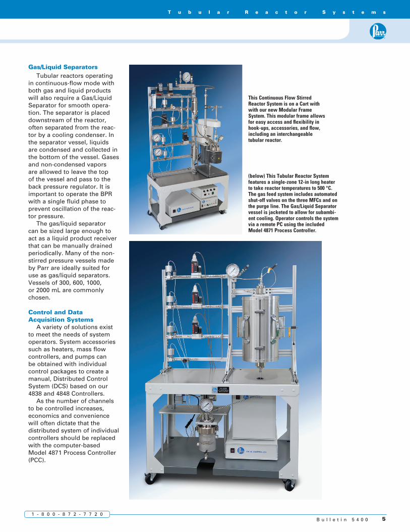
This Continuous Flow Stirred Reactor System is on a Cart with with our new Modular Frame System. This modular frame allows for easy access and flexibility in hook-ups, accessories, and flow, including an interchangeable tubular reactor.
(below) This Tubular Reactor System features a single-zone 12-in long heater to take reactor temperatures to 500 °C. The gas feed system includes automated shut-off valves on the three MFCs and on the purge line. The Gas/Liquid Separator vessel is jacketed to allow for subambi-ent cooling. Operator controls the system via a remote PC using the included Model 4871 Process Controller.
Gas/Liquid SeparatorsTubular reactors operating
in continuous-flow mode with both gas and liquid products will also require a Gas/Liquid Separator for smooth opera-tion. The separator is placed downstream of the reactor, often separated from the reac-tor by a cooling condenser. In the separator vessel, liquids are condensed and collected in the bottom of the vessel. Gases and non-condensed vapors are allowed to leave the top of the vessel and pass to the back pressure regulator. It is important to operate the BPR with a single fluid phase to prevent oscillation of the reac-tor pressure.
The gas/liquid separator can be sized large enough to act as a liquid product receiver that can be manually drained periodically. Many of the non-stirred pressure vessels made by Parr are ideally suited for use as gas/liquid separators. Vessels of 300, 600, 1000, or 2000 mL are commonly chosen.
Control and Data Acquisition Systems
A variety of solutions exist to meet the needs of system operators. System accessories such as heaters, mass flow controllers, and pumps can be obtained with individual control packages to create a manual, Distributed Control System (DCS) based on our 4838 and 4848 Controllers.
As the number of channels to be controlled increases, economics and convenience will often dictate that the distributed system of individual controllers should be replaced with the computer-based Model 4871 Process Controller (PCC).

6 P a r r I n s t r u m e n t C o m p a n yw w w . p a r r i n s t . c o m
Series 5400 Continuous Flow Tubular Reactors
On this page are schematic representations of typical
tubular reactor systems, along with a symbols chart to facili-tate understanding. We have provided an ordering number for each of these examples.
GAS 1S
Purge
PT
T/C
T/C
T/C
BPR
Vent
T/C
Gas1S
MFCF
Gas 2S
MFCF
Liquid
4871Process
Controller
PIC
PG
Purge
FIC
Gas
Liquid
F
F
F
MFC
T/C
PT
PG
T/C
TIC
Key to Symbols
Order No. for this system would be: 5402B-SS-115-ST1(6)-1500-DCS-GF(1)-PL-LF(1)-ITW-CCD-GLS(300)-MPC
Order No. for this system would be: 5403F-SS-230-ST3(24)-3000-PCC-GF(2)-PL-LF(1)-ISP-CSS-ITW-GLS(600)-APC-ASV(3)
Single-zone Tubular Reactor System with one Liquid Feed, one Gas Feed, and one Purge Line.
Inlet
PG
Pressure Gage
PT
Pressure Transducer
T/C
Thermocouple
FIC
Flow IndicatingController
PIC
Pressure IndicatingController
Ball Valve
Needle Valve
Metering
Rupture Disc
3-way
Check Valve
Relief Valve
FFilter
MFCMass Flow Controller
SIC
Speed IndicatingController
MFM
Mass Flow Meter
TIC
TemperatureIndicatingController
PumpTank PressureRegulator
Back PressureRegulator
S
Electric-ActuatedAir-Operated
Solenoid Valve

7B u l l e t i n 5 4 0 01 - 8 0 0 - 8 7 2 - 7 7 2 0
T u b u l a r R e a c t o r S y s t e m s
Series 5400 Ordering Guide
Base ModelModel No. Size (O.D. / I.D.)5401 3/8 in. (0.38” / 0.28”)5402 1/2 in. (0.50” / 0.37”)5403 1.0 in. (1.9” / 1.0”)5404 1.5 in. (2.0” / 1.5”)
Add suffix F for Floor Stand mountingAdd suffix B for Bench Top mounting
Materials of Construction -SS T316 Stainless Steel-HC Alloy 276-TI Titanium-IN Alloy 600-MO Alloy 400
Electrical Supply -115 115 VA, 50/60Hz-230 230 VAC, 50/60Hz
Heater Options-ST1(#) Split Tube, 1-Zone-ST3(#) Split Tube, 3-Zone-FM(#) Flexible Mantle-WJ(#) Welded JacketAdd suffix (6), (12), (24), (36) for heated length (in.)
Maximum Operating Pressure-1500 1500 psi / 100 bar-3000 3000 psi / 200 bar-4500 4500 psi / 300 bar
Controller -PCC PC-based Process Control (4871-style)-DCS Distributed Control System (4838-style)
Custom Options-GF(#) Number of Gas Feeds-PL Purge Gas Feed Line-LF(#) Number of Liquid Feeds-ISP Internal Pre-heat Spiral (5403/5404 only)-CSS Catalyst Support Spools (5403/5404 only)-ITW Internal Thermowell, with Movable T/C-IZT Internal, Zoned, Fixed T/Cs-CCD Cooling Condenser-GLS(#) Gas/Liquid Separator (300, 600, 1000, 2000 mL)-SPH Separator Heater-MPC Manual Pressure Control-APC* Automated Pressure Control-ASV(#)* Automated Shut-off Valves (1-12)*Available only with 4871 Process Control (PCC)
Certifications -No Symbol No Certification Required-PARR Parr Certification-ASME ASME Certification-PED PED Certification-C China
A F
G
H
B
C
D
E
A composite identification number to be used when ordering a 5400 Series Reactor can be developed by combining individual symbols from the separate sections below.

211 53rd StreetMoline, Illinois 61265 USAPhone: 1-309-762-7716 or 1-800-872-7720Fax: 1-309-762-9453E-mail: [email protected]://www.parrinst.com
Bulletin 5400 0516 Printed in USA