Embed Size (px)
Citation preview
1
Part II: Packet Transmission
Packets on a Network
Packets, Frames, LAN, WAN, Hardware Addresses, Bridges, Switches, Routing and
Protocols
Fall 2005
Qutaibah MalluhiComputer Science and Engineering
Qatar University
2
Packets, Frames and Error Detection
3
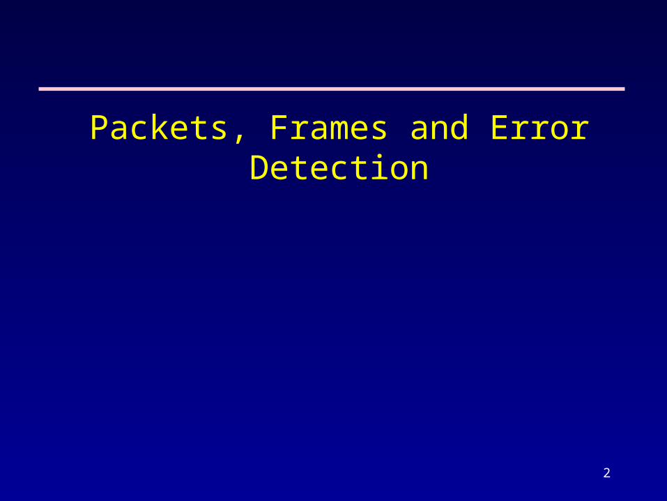
Packet and Circuit Switching
Circuit-switched networks (connection oriented)– Form a dedicated connection (circuit) between two
points
– Guaranteed capacity but high-cost (cost is fixed and is independent of the traffic)
– E.g. telephone system
Computer networks are often called packet switched networks (Connectionless)– Data divided into small pieces (packets)
– Each packet is sent individually
4
Motivation for Packet Switching
Coordination - helps transmitter and receiver determine which data have been received correctly and which have not– Better more efficient control on transmission errors
fair Access - each computer can only send one packet at a time
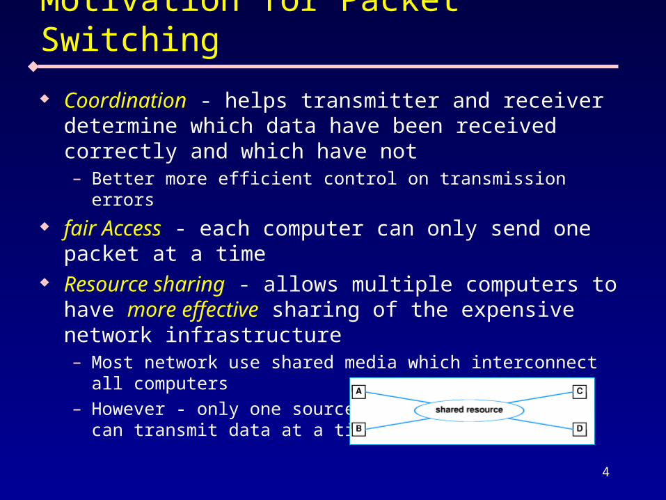
Resource sharing - allows multiple computers to have more effective sharing of the expensive network infrastructure– Most network use shared media which interconnect all
computers – However - only one source
can transmit data at a time
5
Dedicated (non packet-switched) Access
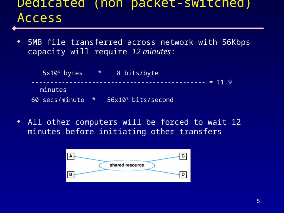
5MB file transferred across network with 56Kbps capacity will require 12 minutes:
5x106 bytes * 8 bits/byte ---------------------------------------------- = 11.9 minutes
60 secs/minute * 56x103 bits/second
All other computers will be forced to wait 12 minutes before initiating other transfers
6
Packet Switched Access
If a 5 MB file is broken into packets, other computers must only wait until packet (not entire file) has been sent
From previous example, suppose file is broken into 1000 byte packets– Each packet takes less than 0.15 seconds to transmit:
1000 bytes * 8 bits/byte ----------------------------------- = 0.143 seconds 56 * 103 bits/second
Other computer must only wait 0.143 seconds before beginning to transmit
Note: – If both files are both 5MB long, each now takes 24 minutes to
transmit – BUT if second file is only 10KB long, it will be transmitted in
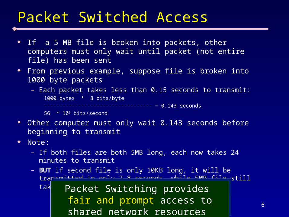
only 2.8 seconds, while 5MB file still takes roughly 12 minutes Packet Switching provides fair and prompt
access to shared network resources Packet Switching provides fair and prompt
access to shared network resources
7
Packets Allow Time Division Multiplexing
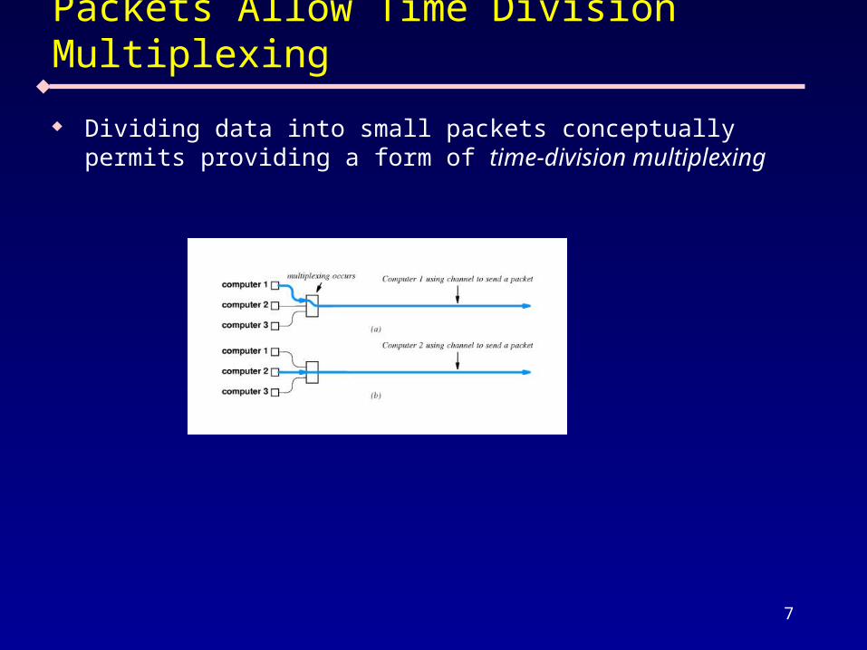
Dividing data into small packets conceptually permits providing a form of time-division multiplexing
8
Packets and frames
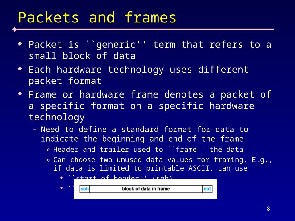
Packet is ``generic'' term that refers to a small block of data
Each hardware technology uses different packet format
Frame or hardware frame denotes a packet of a specific format on a specific hardware technology – Need to define a standard format for data to indicate
the beginning and end of the frame » Header and trailer used to ``frame'' the data» Can choose two unused data values for framing. E.g., if
data is limited to printable ASCII, can use ``start of header'' (soh) ``end of text'' (eot)
9
Frame Delimiters
Incurs extra overhead – soh and eot take time to transmit, but carry no data
Accommodates transmission problems: – Missing eot indicates sending computer crashed – Missing soh indicates receiving computer missed
beginning of message – Bad frame is discarded
10
Data Stuffing
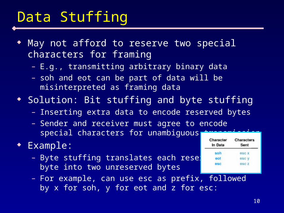
May not afford to reserve two special characters for framing – E.g., transmitting arbitrary binary data – soh and eot can be part of data will be misinterpreted
as framing data Solution: Bit stuffing and byte stuffing
– Inserting extra data to encode reserved bytes– Sender and receiver must agree to encode special
characters for unambiguous transmission Example:
– Byte stuffing translates each reserved byte into two unreserved bytes
– For example, can use esc as prefix, followed by x for soh, y for eot and z for esc:
11
Byte Stuffing
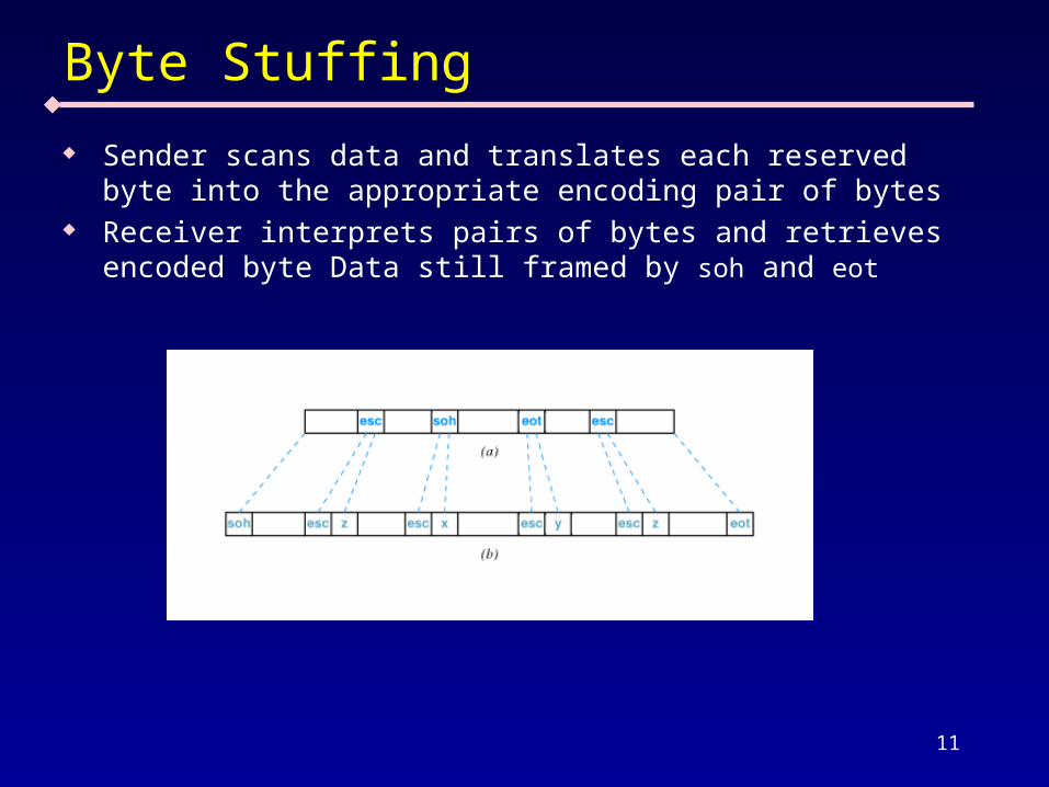
Sender scans data and translates each reserved byte into the appropriate encoding pair of bytes
Receiver interprets pairs of bytes and retrieves encoded byte Data still framed by soh and eot
12
Bit-Oriented Frames/ Bit Stuffing
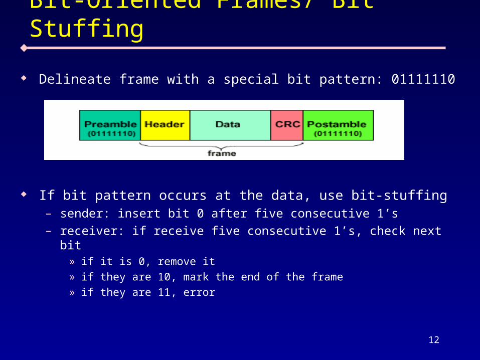
Delineate frame with a special bit pattern: 01111110
If bit pattern occurs at the data, use bit-stuffing– sender: insert bit 0 after five consecutive 1’s– receiver: if receive five consecutive 1’s, check next bit
» if it is 0, remove it» if they are 10, mark the end of the frame» if they are 11, error
13
Transmission Errors
Transmission errors can occur due to interference from external electromagnetic signals – Data can be changed – Data can be lost – Unwanted data can be generated

14
Error detection and correction
Error detection– send additional information so incorrect data can be
detected and rejected– retransmission used to recover from errors– Use for low error rate in data communication
Error correction – send additional information so incorrect data can be
detected, corrected and accepted– higher overhead, used only if retransmission is
impractical, such as simplex transmission, long delay, high error rate
No error control– real time traffic (e.g. real time voice and video)– does not require a 100% error rate
15
Error Detection Techniques
Will See three techniques– Parity– Checksum– Cyclic redundancy check (CRC)
Checksum and CRC are two widely used techniques
16
Parity Error Detection
A parity bit is an extra bit transmitted with a data item Parity refers to the number of bits set to 1 in the data item
– Even parity - an even number of bits are 1» data: 10011101, parity bit 1» use XOR to compute
– Odd parity - an odd number of bits are 1» data: 10011101, parity bit 0» use XNOR to compute
Procedure:– Transmitter and receiver agree on which parity to use– Sender computes parity bit and sends it with data– If a transmission error changes one of the bits in the data from a
1 to a 0 or from a 0 to a 1, parity of resulting bits will be wrong – Receiver detects error in data because of incorrect parity
Parity can only detect odd or practically single-bit errors (not even bit errors)
17
Checksum
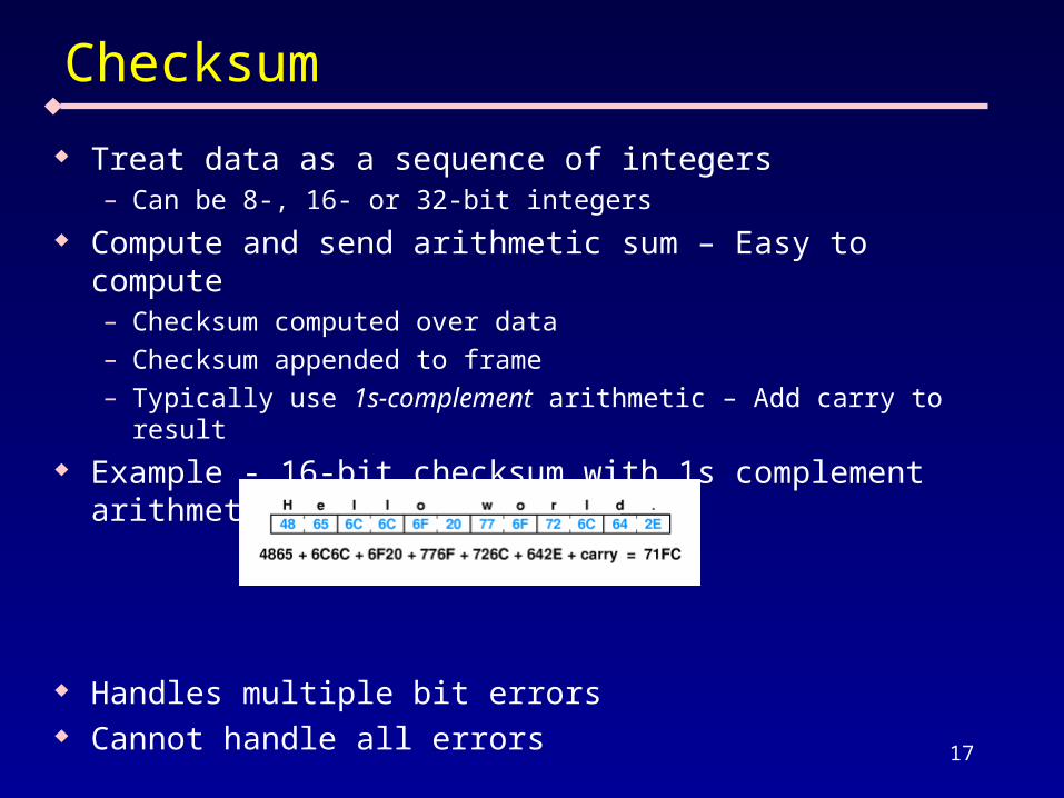
Treat data as a sequence of integers– Can be 8-, 16- or 32-bit integers
Compute and send arithmetic sum – Easy to compute– Checksum computed over data– Checksum appended to frame– Typically use 1s-complement arithmetic – Add carry to result
Example - 16-bit checksum with 1s complement arithmetic
Handles multiple bit errors Cannot handle all errors
18
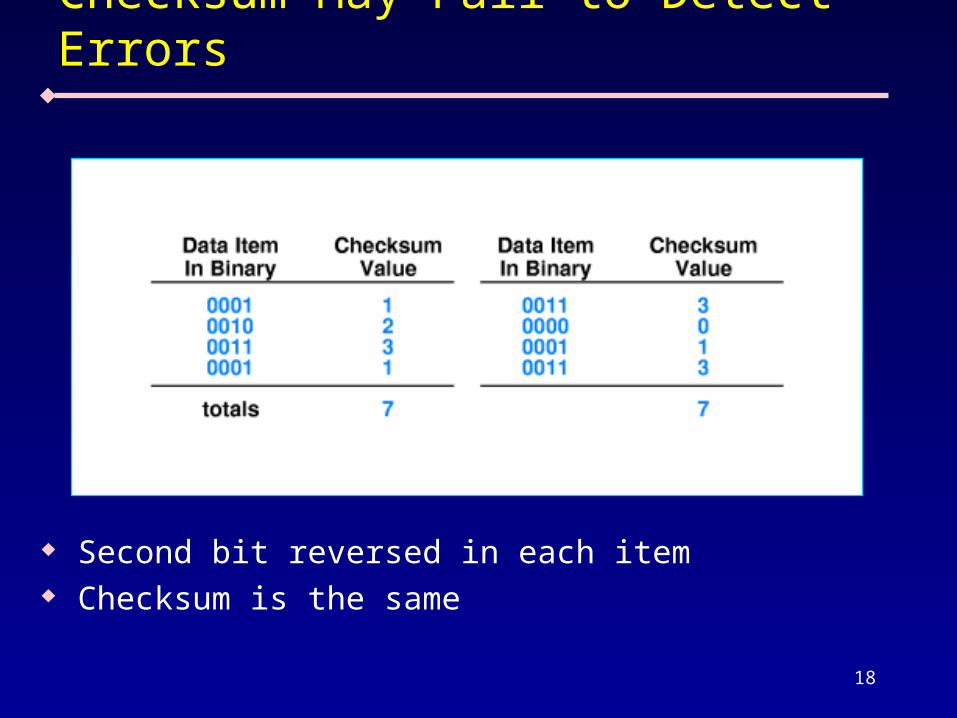
Checksum May Fail to Detect Errors
Second bit reversed in each item Checksum is the same
19
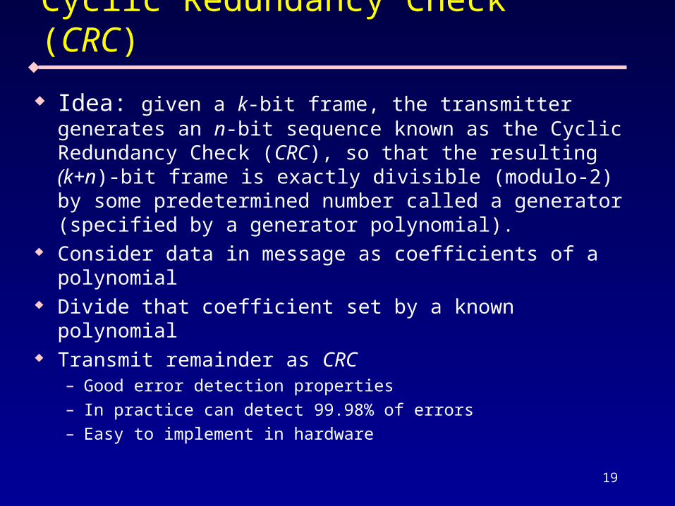
Cyclic Redundancy Check (CRC)
Idea: given a k-bit frame, the transmitter generates an n-bit sequence known as the Cyclic Redundancy Check (CRC), so that the resulting (k+n)-bit frame is exactly divisible (modulo-2) by some predetermined number called a generator (specified by a generator polynomial).
Consider data in message as coefficients of a polynomial
Divide that coefficient set by a known polynomial Transmit remainder as CRC
– Good error detection properties – In practice can detect 99.98% of errors– Easy to implement in hardware
20
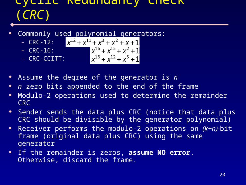
Cyclic Redundancy Check (CRC) Commonly used polynomial generators:
– CRC-12: – CRC-16:– CRC-CCITT:
Assume the degree of the generator is n n zero bits appended to the end of the frame Modulo-2 operations used to determine the remainder CRC Sender sends the data plus CRC (notice that data plus CRC
should be divisible by the generator polynomial) Receiver performs the modulo-2 operations on (k+n)-bit frame
(original data plus CRC) using the same generator If the remainder is zeros, assume NO error. Otherwise,
discard the frame.
1231112 xxxxx121516 xxx151216 xxx
21
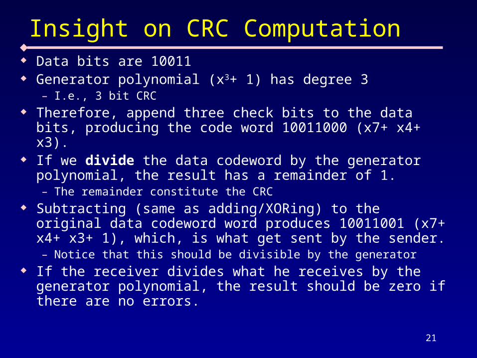
Insight on CRC Computation Data bits are 10011 Generator polynomial (x3+ 1) has degree 3
– I.e., 3 bit CRC Therefore, append three check bits to the data bits, producing
the code word 10011000 (x7+ x4+ x3). If we divide the data codeword by the generator polynomial,
the result has a remainder of 1. – The remainder constitute the CRC
Subtracting (same as adding/XORing) to the original data codeword word produces 10011001 (x7+ x4+ x3+ 1), which, is what get sent by the sender.– Notice that this should be divisible by the generator
If the receiver divides what he receives by the generator polynomial, the result should be zero if there are no errors.
22
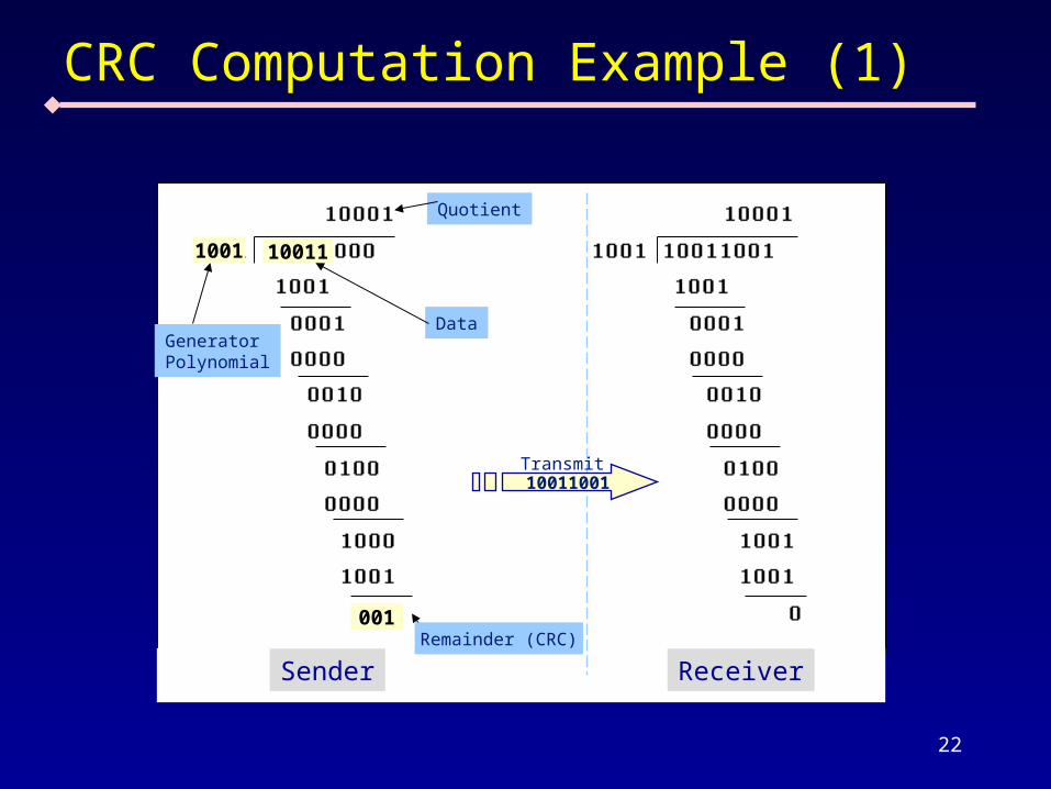
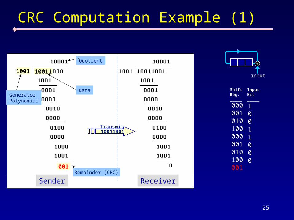
CRC Computation Example (1)
GeneratorPolynomial
Data
Quotient
1001 10011
001
Sender Receiver
10011001Transmit
Remainder (CRC)
23
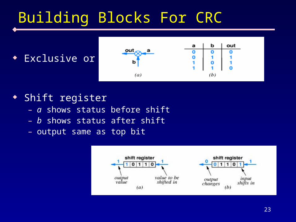
Building Blocks For CRC
Exclusive or
Shift register– a shows status before shift– b shows status after shift– output same as top bit
24
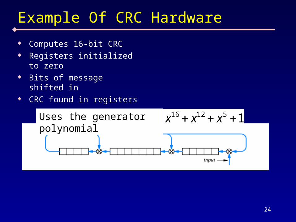
Example Of CRC Hardware
Computes 16-bit CRC Registers initialized to
zero Bits of message shifted in CRC found in registers
151216 xxxUses the generator polynomial
25
CRC Computation Example (1)
GeneratorPolynomial
Data
Quotient
1001 10011
001
Sender Receiver
10011001Transmit
Remainder (CRC)
000001010100000001010100001
10011000
ShiftReg._____
InputBit_____
+
input
26
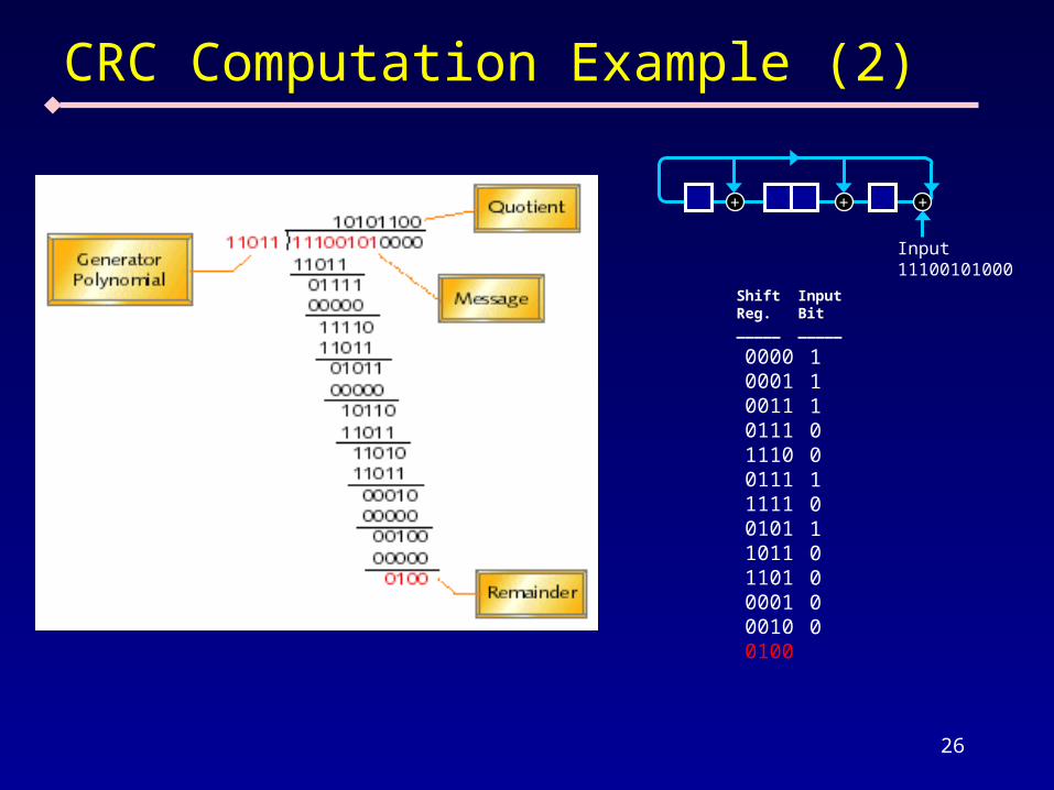
CRC Computation Example (2)
0000000100110111111001111111010110111101000100100100
111001010000
ShiftReg._____
InputBit_____
+
Input11100101000
+ +
27
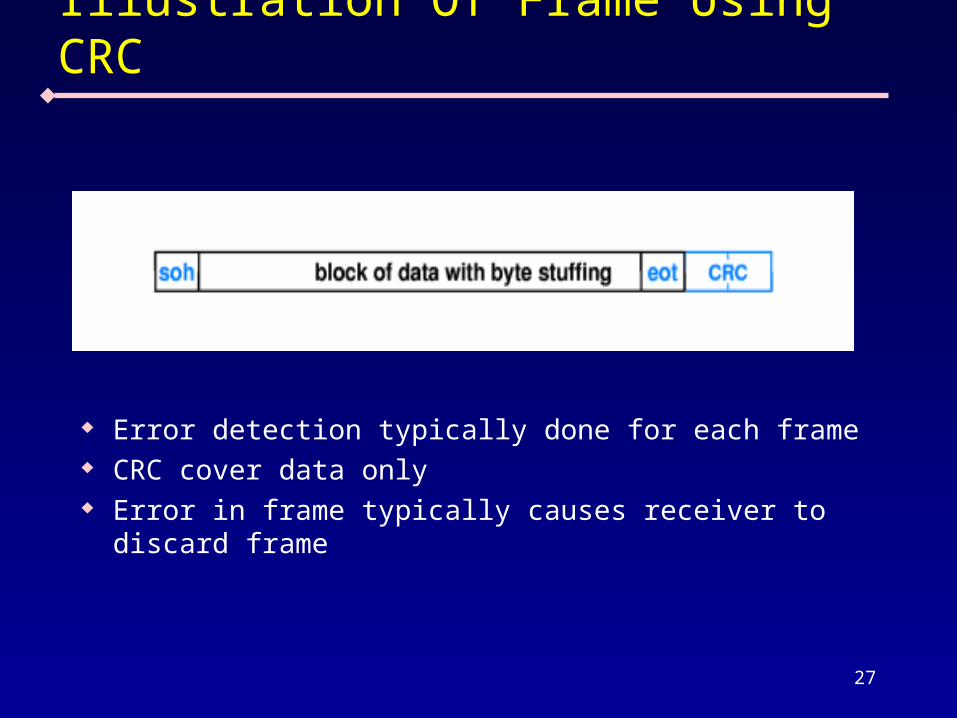
Illustration Of Frame Using CRC
Error detection typically done for each frame CRC cover data only Error in frame typically causes receiver to discard
frame
28
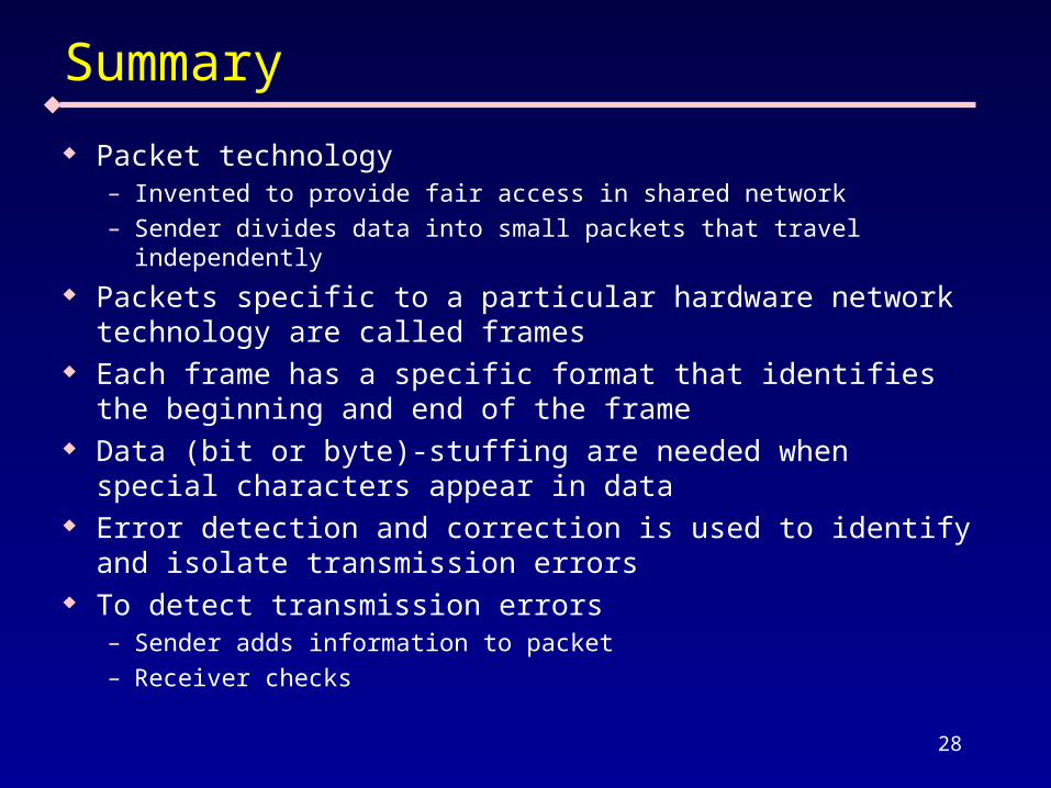
Summary
Packet technology– Invented to provide fair access in shared network– Sender divides data into small packets that travel independently
Packets specific to a particular hardware network technology are called frames
Each frame has a specific format that identifies the beginning and end of the frame
Data (bit or byte)-stuffing are needed when special characters appear in data
Error detection and correction is used to identify and isolate transmission errors
To detect transmission errors– Sender adds information to packet– Receiver checks