Embed Size (px)
Citation preview
1
“Power Amplifier Linearisation for HAP Payload”
Neuchatel, October, 2005
Universitat Politècnica de Catalunya, UPC
2
PROBLEM RATIONALE
3
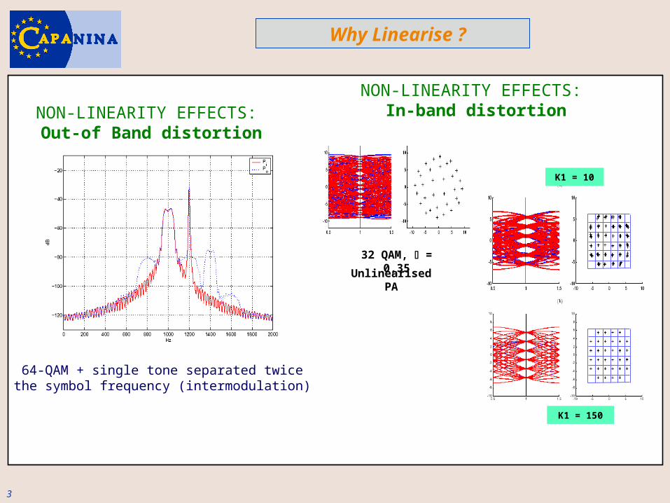
64-QAM + single tone separated twice the symbol frequency (intermodulation)
NON-LINEARITY EFFECTS: Out-of Band distortion
Why Linearise ?
32 QAM, = 0,35
Unlinearised PA
NON-LINEARITY EFFECTS: In-band distortion
K1 = 10
K1 = 150
4
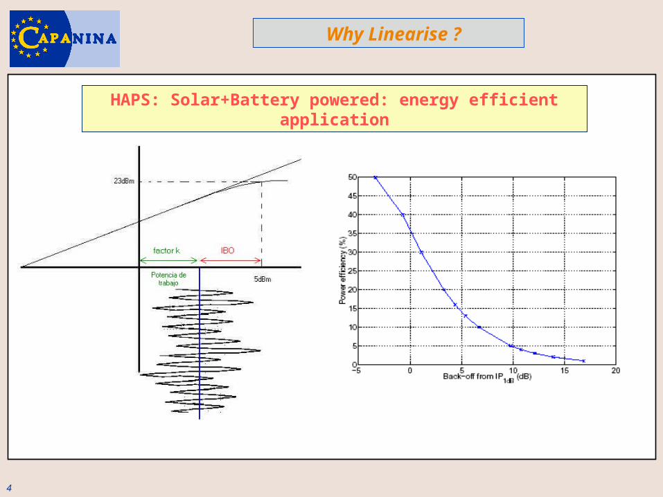
HAPS: Solar+Battery powered: energy efficient application
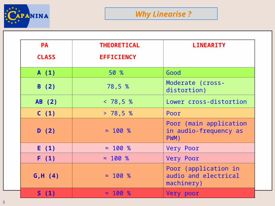
Why Linearise ?
5
PA
CLASS
THEORETICAL
EFFICIENCY
LINEARITY
A (1) 50 % Good
B (2) 78,5 % Moderate (cross-distortion)
AB (2) < 78,5 % Lower cross-distortion
C (1) > 78,5 % Poor
D (2) ≈ 100 %Poor (main application in audio-frequency as PWM)
E (1) ≈ 100 % Very Poor
F (1) ≈ 100 % Very Poor
G,H (4) ≈ 100 %Poor (application in audio and electrical machinery)
S (1) ≈ 100 % Very poor
Why Linearise ?
6
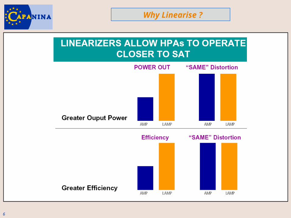
Why Linearise ?

7
HARWARE: CURRENT STATUS IN UPC
8
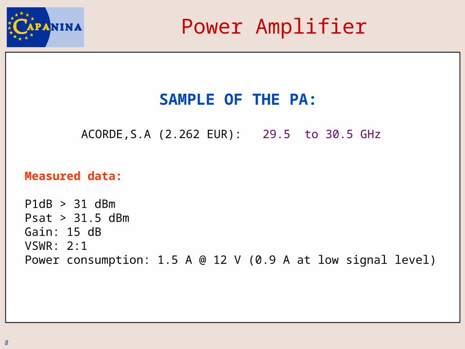
Power Amplifier
SAMPLE OF THE PA:
ACORDE,S.A (2.262 EUR): 29.5 to 30.5 GHz
Measured data:
P1dB > 31 dBmPsat > 31.5 dBmGain: 15 dBVSWR: 2:1Power consumption: 1.5 A @ 12 V (0.9 A at low signal level)
9
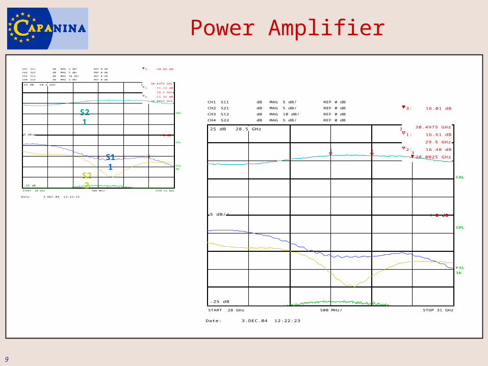
Power Amplifier
28.5 GHz 30.5 GHz
5 dB/
-25 dB
25 dB 28.5 GHz 30.5 GHz
5 dB/
-25 dB
25 dB 28.5 GHz 30.5 GHz
10 dB/
-50 dB
50 dB 28.5 GHz 30.5 GHz
5 dB/
-25 dB
25 dB
CH1
CH2
5 dB/
5 dB/
REF 0 dB
REF 0 dBCH2
CH3
5 dB/
10 dB/
REF 0 dB
REF 0 dBCH3
CH4
10 dB/
5 dB/
REF 0 dB
REF 0 dBCH4 5 dB/ REF 0 dB
CPL
MAG
MAG
dB
dB MAG
MAG
dB
dB S12
S22
MAG
MAG
dB
dB S22 MAGdB
FIL1k 1k FIL1k 1k
CAL
S21
START 28 GHz STOP 31 GHz500 MHz/
S11
1 2 3
3: -10.89 dB
30.4975 GHz
1: -11.12 dB
29.5 GHz
2: -11.31 dB
30.0025 GHz
á 0 dBá 0 dBá 0 dBá 0 dB
Date: 3.DEC.04 12:23:15
S11
S22
S21
28.5 GHz 30.5 GHz
5 dB/
-25 dB
25 dB 28.5 GHz 30.5 GHz
5 dB/
-25 dB
25 dB 28.5 GHz 30.5 GHz
10 dB/
-50 dB
50 dB 28.5 GHz 30.5 GHz
5 dB/
-25 dB
25 dB
CH1
CH2
5 dB/
5 dB/
REF 0 dB
REF 0 dBCH2
CH3
5 dB/
10 dB/
REF 0 dB
REF 0 dBCH3
CH4
10 dB/
5 dB/
REF 0 dB
REF 0 dBCH4 5 dB/ REF 0 dB
CPL
MAG
MAG
dB
dB MAG
MAG
dB
dB S12
S22
MAG
MAG
dB
dB S22 MAGdB
FIL1k 1k FIL1k 1k
CAL
S11
S21
START 28 GHz STOP 31 GHz500 MHz/
S21
1 2 3
3: 16.01 dB
30.4975 GHz
1: 16.61 dB
29.5 GHz
2: 16.48 dB
30.0025 GHz
á 0 dBá 0 dBá 0 dBá 0 dB
Date: 3.DEC.04 12:22:23
10
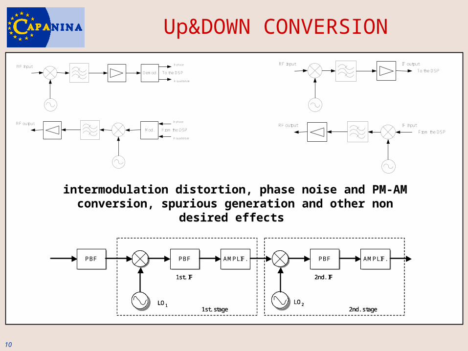
Up&DOWN CONVERSION
Demod.
RF input
To the DSP
In phase
In quadrature
Mod.
RF output
From the DSP
In phase
In quadrature
RF input
To the DSP
RF output
From the DSP
IF output
IF input
PBFPBF PBFPBF AMPLIF.AMPLIF. PBFPBF AMPLIF.AMPLIF.
LO2LO1
1st. IF 2nd. IF
1st. stage 2nd. stage
PBFPBF PBFPBF AMPLIF.AMPLIF. PBFPBF AMPLIF.AMPLIF.
LO2LO1
1st. IF 2nd. IF
1st. stage 2nd. stage
intermodulation distortion, phase noise and PM-AM conversion, spurious generation and other non desired
effects
11
Power Amplifier LinearisationTest and measuring equipment
Signal generation:ESG Signal generator: E4433B (modulated signals up to 4 GHz)PSW CW Signal generator E8247C (carriers up to 40 GHz).
Spectrum analysis:ESA Spectrum analyser: E4407 (vector signal analyser, up to 26.5 GHz).ENLARGEMENT OF SPECTRUM ANALYSIS UP TO 40 GHz: E4407BK-AXY (External Mixer) + 11974A (millimetre mixer) 26,5-40 GHz
(Equipment purchased with founds from other projects)
Additional equipment has been ordered, expected delivery time: next November CABLES/CONNECTORS, UP-DOWN CONVERTERS (30 GHz), …
12
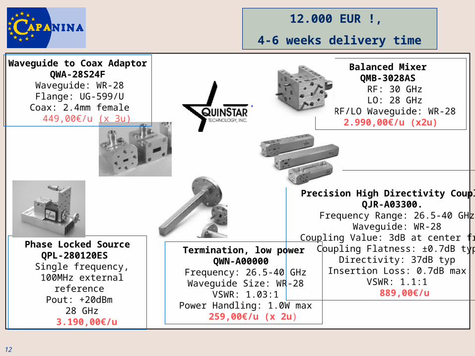
Balanced Mixer QMB-3028AS
RF: 30 GHz LO: 28 GHz
RF/LO Waveguide: WR-28 2.990,00€/u (x2u)
Phase Locked SourceQPL-280120ES Single frequency,100MHz external
reference Pout: +20dBm
28 GHz 3.190,00€/u
Precision High Directivity CouplerQJR-A03300.
Frequency Range: 26.5-40 GHz Waveguide: WR-28
Coupling Value: 3dB at center freq. Coupling Flatness: ±0.7dB typ
Directivity: 37dB typ Insertion Loss: 0.7dB max
VSWR: 1.1:1 889,00€/u
Termination, low powerQWN-A00000
Frequency: 26.5-40 GHz Waveguide Size: WR-28
VSWR: 1.03:1 Power Handling: 1.0W max
259,00€/u (x 2u)
Waveguide to Coax Adaptor QWA-28S24F
Waveguide: WR-28 Flange: UG-599/U
Coax: 2.4mm female 449,00€/u (x 3u)
12.000 EUR !,
4-6 weeks delivery time

13
LINEARISATION STRATEGIES
(BASE BAND)
A: ANALOGUE

14
Power Amplifier Linearisation
DISCARDED ALTERNATIVES (already
reported in previous meetings):
• Feedback (and its variants: RF, envelope, cartesian, polar) –
instability-
• Feedforward –quite sensitive to loop mismatches:
milimeter band, 2 Pas
• LINC /CALLUM - 2 PAs, loop balances: milimeter band –
• EE&R (envelope elimination and restoration) - time constants
in the envelope loop (28 MHz bandwidth: risked) -

15
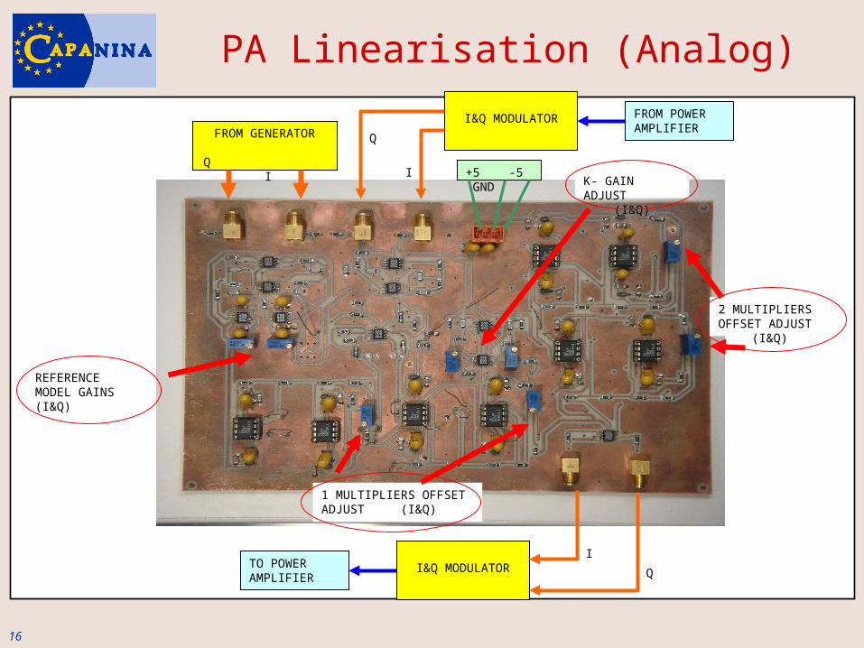
PA Linearisation (Analog)
CONSIDERED ALTERNATIVES (already reported
previously):
1.- Hyperstable lineariser (analog)
12 dB
26 dB
Clase A. OBO = 3 dB. Po = 24,8 dBm. IP3= 19 dBm
Only AM/AM distortion
16
FROM GENERATOR
Q I
I&Q MODULATOR FROM POWER AMPLIFIER
I&Q MODULATORTO POWER AMPLIFIER
REFERENCE MODEL GAINS (I&Q)
2 MULTIPLIERS OFFSET ADJUST
(I&Q)
1 MULTIPLIERS OFFSET ADJUST (I&Q)
K- GAIN ADJUST(I&Q)
+5 -5 GND
Q
I
Q
I
PA Linearisation (Analog)
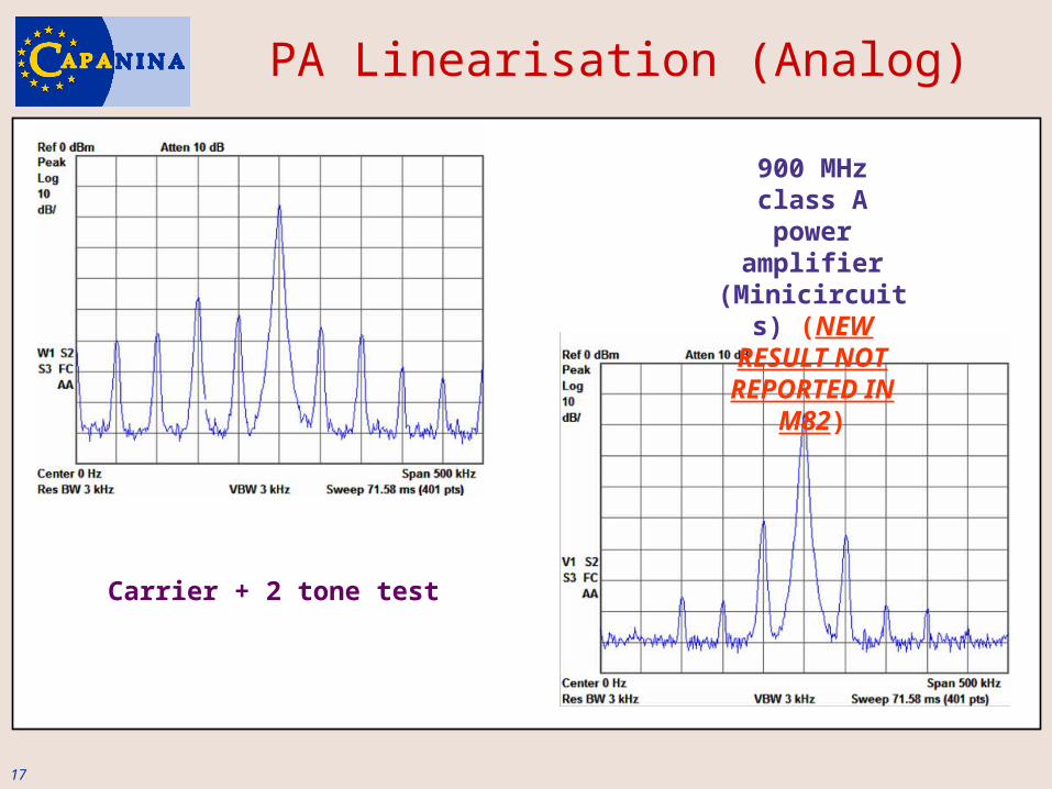
17
900 MHz class A power
amplifier (Minicircuits)
(NEW RESULT NOT REPORTED IN
M82)
PA Linearisation (Analog)
Carrier + 2 tone test
18
LINEARISATION STRATEGIES
(IF-sampling)
B: DIGITAL
19
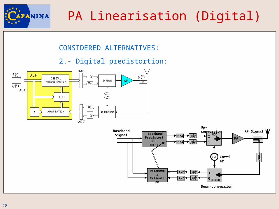
CONSIDERED ALTERNATIVES:
2.- Digital predistortion:
IQ MOD AP
ADAPTATION
LUT
DIGITALPREDISTORTER
IQ DEMOD
( )i t
( )q t
( )y t
ADC
ADC
DACDSP
PAI
Q
MOD
Up-conversion
I
QDEMOD
Carrier
Down-conversion
D/A
D/A
A/D
A/DParameterEstimation
BasebandPredistorter
(·)
Baseband Signal
RF Signal
PA Linearisation (Digital)

20
LOW-PASS FILTER
LOW-PASS FILTER
OSCILLATOR
90º PHASE SHIFTER
I COMPONENT
Q COMPONENT
PA Linearisation (Digital)
ANALOG: + cost, + spurious
- Computing time consumption (Nyquist)
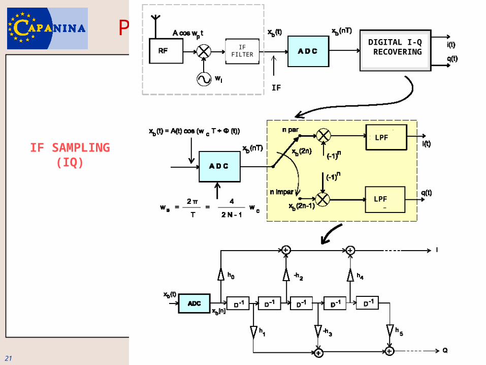
21
PA Linearisation (Digital)IF
FILTER
DIGITAL I-Q
RECOVERING
LPF
LPF
IF
IF SAMPLING (IQ)
22
• Phase noise and frequency stability
• Clock jitter
• In MOS technology, the power consumption of a DSP device is
approximately proportional to the clock frequency
• Frequency distortion introduced by D/A converters
PA Linearisation (Digital)
23
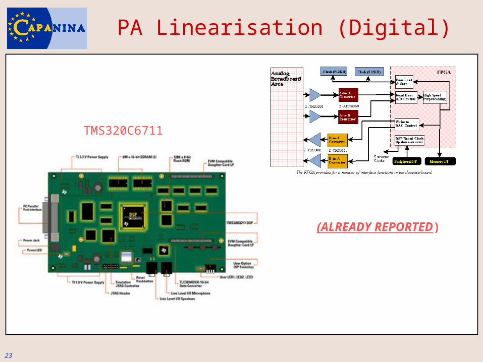
PA Linearisation (Digital)
TMS320C6711
(ALREADY REPORTED)
24
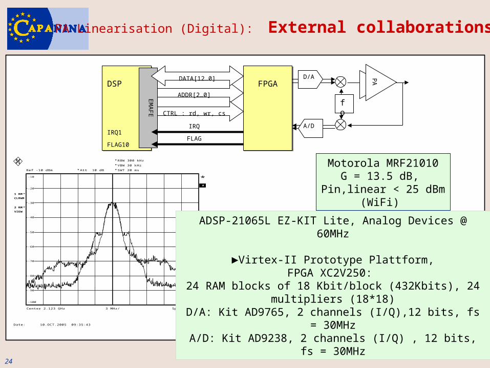
DSPDSP FPGAFPGAADDR[2…0]
CTRL : rd, wr, cs
IRQIRQ1
FLAGFLAG10
EM
AF
E
DATA[12…0] PA
fo
D/A
A/D
RBW 300 kHzVBW 30 kHzSWT 20 ms
*
*
A
Ref -10 dBm
Center 2.123 GHz Span 30 MHz3 MHz/
Att 10 dB*
*
*1 RMCLRWR
*2 RMVIEW
*
PRN
-100
-90
-80
-70
-60
-50
-40
-30
-20
-10
Date: 10.OCT.2005 09:35:43
Motorola MRF21010G = 13.5 dB,
Pin,linear < 25 dBm(WiFi)
ADSP-21065L EZ-KIT Lite, Analog Devices @ 60MHz
►Virtex-II Prototype Plattform,FPGA XC2V250:
24 RAM blocks of 18 Kbit/block (432Kbits), 24 multipliers (18*18)
D/A: Kit AD9765, 2 channels (I/Q),12 bits, fs = 30MHzA/D: Kit AD9238, 2 channels (I/Q) , 12 bits, fs = 30MHz
PA Linearisation (Digital): External collaborations
25
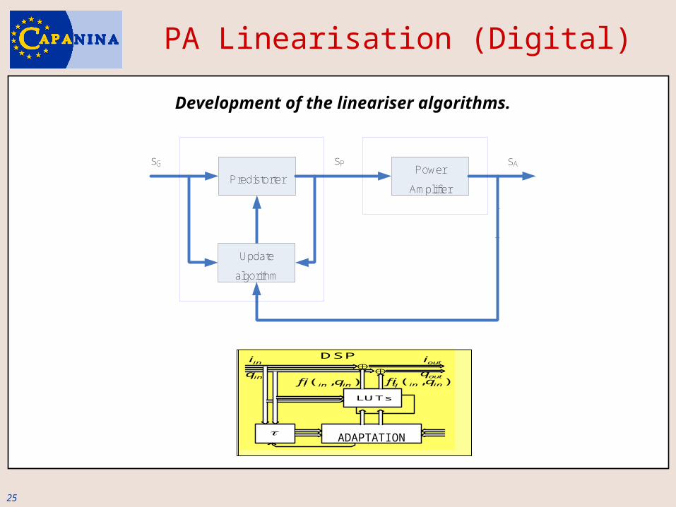
Development of the lineariser algorithms.
+
-
y
PredistorterPower
Amplifier
Update
algorithm
sG sAsP
ADAPTACIÓN
LUTs
DSP
ini
( , )i in inf i q
( , )q in inf i qinq
outi
outq
ADAPTATION
PA Linearisation (Digital)
26
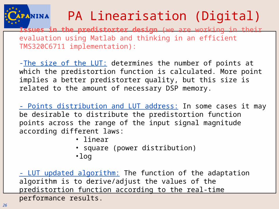
Issues in the predistorter design (we are working in their evaluation using Matlab and thinking in an efficient TMS320C6711 implementation):
-The size of the LUT: determines the number of points at which the predistortion function is calculated. More point implies a better predistorter quality, but this size is related to the amount of necessary DSP memory.
- Points distribution and LUT address: In some cases it may be desirable to distribute the predistortion function points across the range of the input signal magnitude according different laws:
• linear• square (power distribution)•log
- LUT updated algorithm: The function of the adaptation algorithm is to derive/adjust the values of the predistortion function according to the real-time performance results.
PA Linearisation (Digital)
27
.
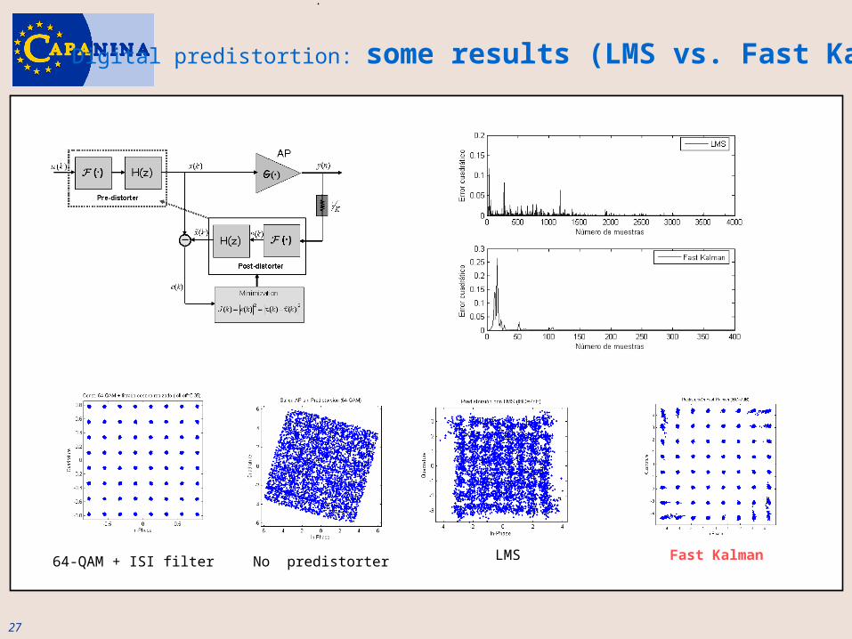
64-QAM + ISI filter No predistorter LMS Fast Kalman
Digital predistortion: some results (LMS vs. Fast Kalman)
28
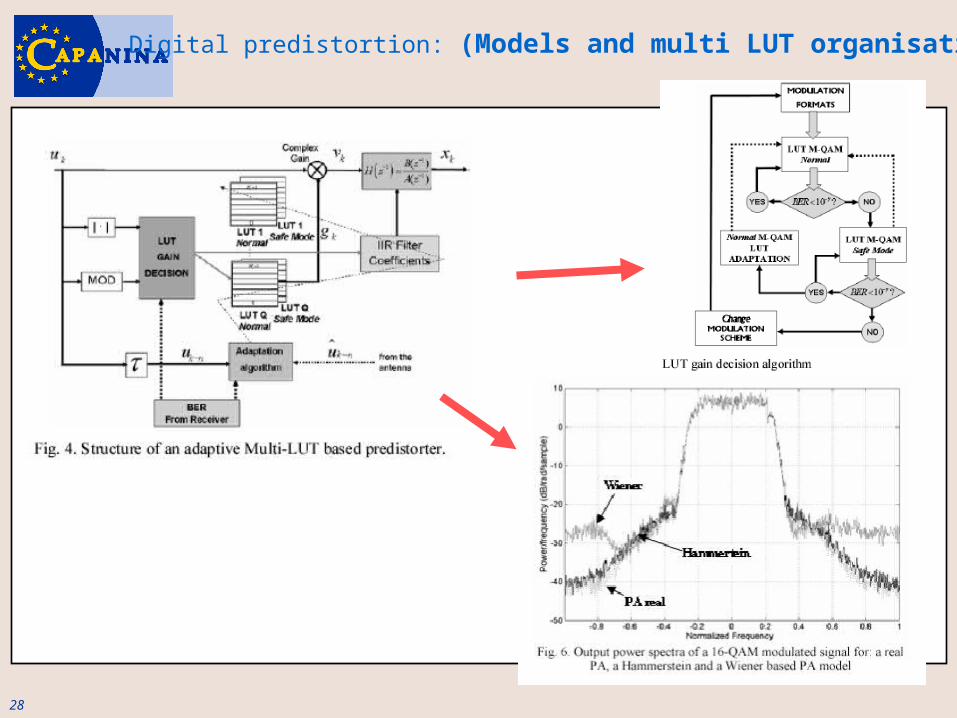
Digital predistortion: (Models and multi LUT organisation)

29

30
http://cmc.upc.es