Embed Size (px)
Citation preview

1
Processor Design5Z032
SystemC + miniMIPS
Henk CorporaalEindhoven University of Technology
2011

© PG/HC 2008 Programming 5JJ70 pg 2
SystemC and our MIPS project
• As part of the lab you’ll be building a real MIPS processor– Here we discuss the so-called mmMIPS (miniminiMIPS)
• based on your book, ch 5 and 6 (3rd ed) / ch 4 (4th ed)– It has only 9 instructions, in 3 categories:
• arithmetic• data load and store• branch and jump
– Described in SystemC
• In the lab (exercise B) we directly start with the mMIPS (miniMIPS)
– it has about 35 instructions– it can run C-code by using the available LCC C-compiler
• SystemC; we discuss– basics (module example, tracing, main function)– modules and submodules– processes– data types

© PG/HC 2008 Programming 5JJ70 pg 3
mmMIPS (pipelined version)

© PG/HC 2008 Programming 5JJ70 pg 4
Hardware-software co-design• We’re designing a processor system.
– This is hardware that runs software.• We need to design BOTH hardware and software
– Hence the name: Hardware-Software co-design.
• In our case the hardware is an FPGA. In real life this could be a multi-million dollar chip that takes 6 months to implement in hardware.
• We need to emulate/simulate the hardware before we’re actually making it. In this way errors can be found early on.
• A simulation model of the hardware can be described in ‘SystemC’. This is actually a C++ program with a special toolkit.
• We also compile our SystemC processor into FPGA hardware; so we use SystemC for 2 purposes.
Hardware
Software
System

© PG/HC 2008 Programming 5JJ70 pg 5
Overview of mmMIPS design trajectory
FPGA hardware:Your MIPS processorsystem
Running the simulation program:Your MIPS processorsystem ram
machine code
(program)
SystemC model of mini-mini MIPS(bunch of C++ files)
rammachine
code(program)
C++ compilerSynopsysCoCentric compiler
Analyze:waveform, etc
Analyze: Oscilloscope,logic analyzer, etc.
mips-as.exeMIPS assembler
lcc.exeC compiler
machine code
(program)
subsetof MIPSinstructions

© PG/HC 2008 Programming 5JJ70 pg 6
Programming flowC-programfile.c
MIPSassemblerfile.asm
Compilerlcc.exe
Assemblermips-as.exe
HDD hex editorhex-editor.exe
Object codefile.o
Object codefile.o
Disassemblerdisas
MIPSassembler
Model of mipssingle-cycle.exe
C++ compilerVisual C++
C++ sourcemain.cppC++ source
main.cppC++ sourcemain.cppC++ source
main.cpp
Simulation outputmips.vcd
MIPS simulatorspim.exe
GTK Signal analyzerwinwave.exe
runs in cygwin
runs in Windows
Initially we start here
To strip the first 34 bytes
SystemC modelof miniminiMIPS
software hardware

© PG/HC 2008 Programming 5JJ70 pg 7
Getting all this stuff
• We’ve collected all tools you need in a single (BIG) file 176MByte file. Go to the directory web site
http://www.es.ele.tue.nl/education/Computation/mmips-lab
For download instructions.
• This will install:– HDD Hex Editor– Cygwin– PC Spim- WinWave- SystemC stuff for Borland/Visual C++- LCC- Single Cycle Minimips in SystemC, Multi-cycle Minimips and
pipelined MIPS.

© PG/HC 2008 Programming 5JJ70 pg 8
cygwin
• Some of the programs we use (LCC, the MIPS assembler) are written as UNIX tools.
• The distribution contains a GNU Unix environment called cygwin.
• This is a command-line shell. •cd /cygdrive/<drivename> to get to the windows disks.

© PG/HC 2008 Programming 5JJ70 pg 9
Getting around in cygwin
$ whoamihenk$ pwd/$ lsbin cygwin.ico home lib setup.log.full usrcygwin.bat etc include setup.log tmp var$ cd /cygdrive/c/Ogo1.2/lcc/lccdir$ ls -l mips-as.exe-rwxr-xr-x 1 henk unknown 2472629 Nov 22 14:35 mips-as.exe$ PATH=/cygdrive/c/Ogo1.2/lcc/lccdir:$PATH$ cd ../..$ mkdir test$ cd test$ mips-as.exe test.asmhenk@HENK-LAP /cygdrive/c/Ogo1.2/test$ lsa.out test.asm$ disas a.out
Type UNIXcommands here
Which directory am I?
/ = the root
list the directory
go to the windows disk
assembler program
set the search path
run the assembler
run the disassembler
make a new subdirectory

© PG/HC 2008 Programming 5JJ70 pg 10
Circuit description in SystemC
•A number of hardware description languages exist:–Verilog (USA)–VHDL (Japan, Europe)–SystemC (newer)–…
•They allow you to:–Describe the logic and functionality–Describe timing–Describe parallelism (HW = parallel)–Check the consistency–Simulate–Synthesize hardware (well, not always)
© PG/HC 2008 Programming 5JJ70 pg 11
SystemC
•SystemC is a C++ library with class definitions.
•You write some C++ code using the classes. This describes two issues:
–1 Circuit structure (schematic/functionality)–2 Simulation settings
•Compiling and running it will perform the simulation.
•SystemC is just C++ code, though it looks funny.
© PG/HC 2008 Programming 5JJ70 pg 12
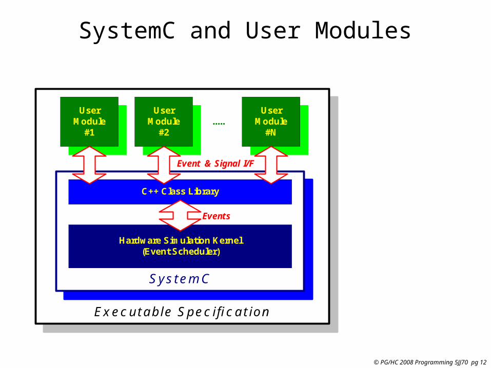
SystemC and User Modules
Executable SpecificationExecutable Specification
SystemCSystemC
Hardware Simulation Kernel(Event Scheduler)
C++ Class Library
UserModule
#1
UserModule
#1
UserModule
#2
UserModule
#2
UserModule
#N
UserModule
#N.....
Event & Signal I/F
Events

© PG/HC 2008 Programming 5JJ70 pg 13
SystemC usesTemplates; let's have a look
• Often we need to use functions that are similar, but that have different data types.
short maximum (short a, short b) { if(a > b) return a; else return b;}
int maximum (int a, int b) { if(a > b) return a; else return b;}
double maximum (double a, double b) { if(a > b) return a; else return b;}
void main(void) { double p = 10.0, q = 12.0; int r = 15, s = 1;
double a = maximum(p, q); int b = maximum(r, s);
}
Can we avoid this duplicationby making the
type a parameter?

© PG/HC 2008 Programming 5JJ70 pg 14
Template functions in C++• Lets build a template, and call that type T
template <class T>T maximum (T a, T b) { if(a > b) return a; else return b;}
void main(void) { double p = 10.0, q = 12.0; int r = 15, s = 1;
double a = maximum(p, q); int b = maximum(r, s);
}
a and b are of type Treturns type T
Declares T as a ‘variable’ type
• Behind the scenes, the compiler builds the routine for each class that is required.
• This is a little heavy on the compiler, and also harder to debug.
Uses the integer type

© PG/HC 2008 Programming 5JJ70 pg 15
Template classes in C++• The same can be done with classes!
template <class T>class coordinate {public: coordinate(T x, T y) { _x = x; _y = y; } ~coordinate();
void print(void) { cout << x << “ , “ << y << endl; }private: T _x, _y;}
void main(void) { coordinate <int> a(1, 2); coordinate <double> b(3.2, 6.4);
a.print(); b.print();}
The class datamembers_x and _y of parameterized type T
• Again, the compiler builds a separate code instance for each type that is required.
1 , 23.2 , 6.4
b is the double incarnationof coordinate.

© PG/HC 2008 Programming 5JJ70 pg 16
SystemC class templates• Lets look at an example:
template <int W>class sc_bv : public sc_bv_base{public: sc_bv(); lrotate( int n ); set_bit(int i, bool value); …}
void main(void) { sc_signal< sc_bv<32> > bus_mux1;}
• The SystemC class structure is rather complicated.• I suggest to single-step through the example to get a feel for it.
32 bit vector
The word width W is the parameter
Signal wires

© PG/HC 2008 Programming 5JJ70 pg 17
A 2-input or-gate class in SystemC
#include <systemc.h>
SC_MODULE(OR2){ sc_in<bool> a; // input pin a sc_in<bool> b; // input pin b
sc_out<bool> o; // output pin o
SC_CTOR(OR2) // the ctor { SC_METHOD(or_process); sensitive << a << b; }
void or_process() { o.write( a.read() || b.read() ); }};
ORa
bo
This include file containsall systemc functions andbase classes.
All systemC classesstart with sc_
This sets up a classcontaining a modulewith a functionality.
Instantiates the input pins a and b.They carry booleansygnals. This object inherits all systemC properties of a pin. how this isactually implemented is hidden from us!
Similarly, a booleanoutput pin called o
This stuff is executedduring constructionof an ‘or2’ object
Tells the simulator which function torun to evaluate theoutput pinThis is run to process
the input pins.
This is the actual or!
Calls read and writemember functionsof pins.
Run the method whensignal a or b changes

© PG/HC 2008 Programming 5JJ70 pg 18
SystemC program structure
#include <systemc.h>#include “and.h”#include “or.h”// etc..
int sc_main(int argc, char *argv[]){
// 1: Instantiate gate objects … // 2: Instantiate signal objects … // 3: Connect the gates to signals …
// 4: specify which values to print
// 5: put values on signal objects
// 6: Start simulator run
}
• First a data structure is built that describes the circuit.
• This is a set of module (cell-)objects with attached pin objects.
• Signal objects tie the pins together.
• Then the simulation can be started.
• The simulation needs:– input values– the list of pins that
is to reported.
© PG/HC 2008 Programming 5JJ70 pg 19
Step 1: make the gate objects
AND5
AND6
OR2OR8
INV9
OR1AND3
AND4
NOR7
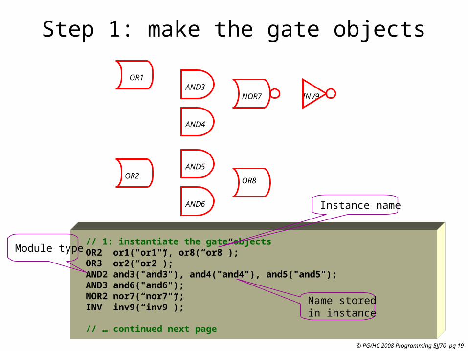
// 1: instantiate the gate objects OR2 or1("or1"), or8(“or8”); OR3 or2(“or2”); AND2 and3("and3"), and4("and4"), and5("and5"); AND3 and6("and6"); NOR2 nor7(“nor7"); INV inv9(“inv9”);
// … continued next page
Instance name
Module type
Name storedin instance

© PG/HC 2008 Programming 5JJ70 pg 20
Step 2: make the signal objects
AND5
AND6
OR2OR8
INV9
OR1AND3
AND4
NOR7
ABCI
SUM
CO
// … continued from previous page
// 2: instantiate the signal objects sc_signal<bool> A, B, CI; // input nets sc_signal<bool> CO, SUM; // output nets sc_signal<bool> or_1, or_2, and_3, and_4; // internal nets sc_signal<bool> and_5, and_6, nor_7; // internal nets
// … continued next page
Booleansignal
Template classused for boolean
or_1
or_2
and_3nor_7
and_4
and_5
and_6

© PG/HC 2008 Programming 5JJ70 pg 21
Step 3: Connecting pins of gates to signals
AND5
AND6
OR2OR8
INV9
OR1AND3
AND4
NOR7
ABCI
SUM
CO
// 3: Connect the gates to the signal nets or1.a(A); or1.b(B); or1.o(or_1); or2.a(A); or2.b(B); or2.c(CI); or2.o(or_2); and3.a(or_1); and3.b(CI); and3.o(and_3); and4.a(A); and4.b(B); and4.o(and_4); and5.a(nor_7); and5.b(or_2); and5.o(and_5); and6.a(A); and6.b(B); and6.c(CI); and6.o(and_6); nor7.a(and_3); nor7.b(and_4); nor7.o(nor_7); or8.a(and_5); or8.b(and_6); or8.o(SUM); inv9.a(nor_7); inv9.o(CO); // … continued next page
Gate instance object or2
pin object o
Signal net object
or_1
or_2
and_3
nor_7
and_4
and_5
and_6

© PG/HC 2008 Programming 5JJ70 pg 22
Running the simulation
// .. continued from previous page sc_initialize(); // initialize the simulation engine
// create the file to store simulation results sc_trace_file *tf = sc_create_vcd_trace_file("trace");
// 4: specify the signals we’d like to record in the trace file sc_trace(tf, A, "A"); sc_trace(tf, B, "B"); sc_trace(tf, CI, “CI"); sc_trace(tf, SUM, “SUM"); sc_trace(tf, CO, "CO");
// 5: put values on the input signals A=0; B=0; CI=0; // initialize the input values sc_cycle(10);
for( int i = 0 ; i < 8 ; i++ ) // generate all input combinations { A = ((i & 0x1) != 0); // value of A is the bit0 of i B = ((i & 0x2) != 0); // value of B is the bit1 of i CI = ((i & 0x4) != 0); // value of CI is the bit2 of i sc_cycle(10); // evaluate } sc_close_vcd_trace_file(tf); // close file and we’re done}

© PG/HC 2008 Programming 5JJ70 pg 23
Waveform viewer
© PG/HC 2008 Programming 5JJ70 pg 24
Modules
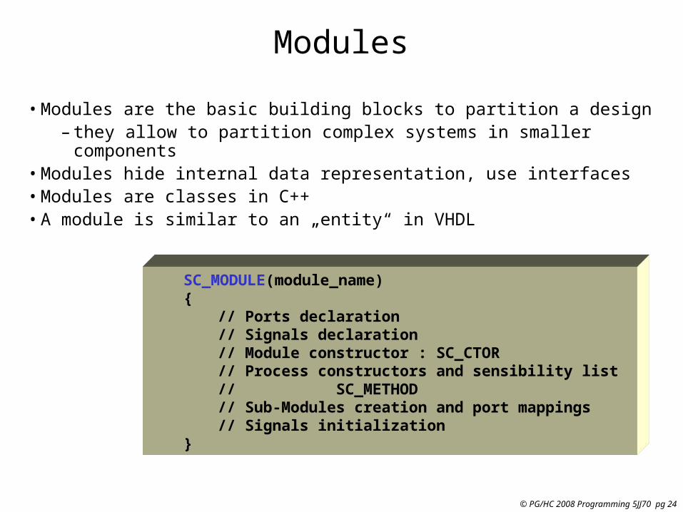
• Modules are the basic building blocks to partition a design– they allow to partition complex systems in smaller
components• Modules hide internal data representation, use interfaces• Modules are classes in C++• A module is similar to an „entity“ in VHDL
SC_MODULE(module_name){
// Ports declaration // Signals declaration// Module constructor : SC_CTOR// Process constructors and sensibility list// SC_METHOD// Sub-Modules creation and port mappings// Signals initialization
}

© PG/HC 2008 Programming 5JJ70 pg 25
A Mux 2:1 module
SC_MODULE( Mux21 ) {
sc_in< sc_uint<8> > in1; sc_in< sc_uint<8> > in2; sc_in< bool > selection; sc_out< sc_uint<8> > out;
void doIt( void );
SC_CTOR( Mux21 ) {
SC_METHOD( doIt ); sensitive << selection; sensitive << in1; sensitive << in2; }};
MUX
in1
in2
selection
out

© PG/HC 2008 Programming 5JJ70 pg 26
Submodules and Connections
Example: 'filter'
filter
s1
sample
din dout
c1
coeff
cout
m1
mult
a
q
b
q
s
c
SC_MODULE(filter) { // Sub-modules : “components sample *s1; coeff *c1; mult *m1;
sc_signal<sc_uint <32> > q, s, c; // Signals // Constructor : “architecture” SC_CTOR(filter) { // Sub-modules instantiation and mapping s1 = new sample (“s1”); s1->din(q); // named mapping s1->dout(s);
c1 = new coeff(“c1”); c1->out(c); // named mapping
m1 = new mult (“m1”); (*m1)(s, c, q); // Positional mapping }}

© PG/HC 2008 Programming 5JJ70 pg 27
3 types of Processes
• Methods– When activated, executes and returns (just like a function)– SC_METHOD(process_name);– no staticly kept state– activated by event on sensitivity list
• Threads– Can be suspended and reactivated– wait() -> suspends execution– activated by event on sensitivity list– SC_THREAD(process_name);
• CThreads– Activated by the clock pulse– SC_CTHREAD(process_name, clock value);

© PG/HC 2008 Programming 5JJ70 pg 28
Defining the Sensitivity List of a Process
• sensitive with the ( ) operator– Takes a single port or signal as argument– sensitive(sig1); sensitive(sig2); sensitive(sig3);
• sensitive with the stream notation– Takes an arbitrary number of arguments– sensitive << sig1 << sig2 << sig3;
• sensitive_pos with either ( ) or << operator– Defines sensitivity to positive edge of Boolean signal or
clock– sensitive_pos << clk;
• sensitive_neg with either ( ) or << operator– Defines sensitivity to negative edge of Boolean signal or
clock– sensitive_neg << clk;

© PG/HC 2008 Programming 5JJ70 pg 29
An Example of an SC_THREAD
void do_count() { while(1) { if(reset) { value = 0; } else if (count) { value++; q.write(value); } wait(); }}
Wait till next event !
Repeat forever

© PG/HC 2008 Programming 5JJ70 pg 30
Thread Processes: wait( ) Function
• wait( ) may be used in both SC_THREAD and SC_CTHREAD processes but not in SC_METHOD process block
• wait( ) suspends execution of the process until the process is invoked again
• wait(<pos_int>) may be used to wait for a certain number of cycles (SC_CTHREAD only)
• In Synchronous process (SC_CTHREAD)
– Statements before the wait( ) are executed in one cycle– Statements after the wait( ) executed in the next cycle
• In Asynchronous process (SC_THREAD)– Statements before the wait( ) are executed in the last
event – Statements after the wait( ) are executed in the next even

© PG/HC 2008 Programming 5JJ70 pg 31
SC_THREAD Example
SC_MODULE(my_module){ sc_in<bool> id; sc_in<bool> clock; sc_in<sc_uint<3> > in_a; sc_in<sc_uint<3> > in_b; sc_out<sc_uint<3> > out_c; void my_thread();
SC_CTOR(my_module) { SC_THREAD(my_thread); sensitive << clock.pos(); }};
//my_module.cpp
void my_module:: my_thread(){ while(true) { if (id.read()) out_c.write(in_a.read()); else out_c.write(in_b.read()); wait(); }};
Thread implementation:

© PG/HC 2008 Programming 5JJ70 pg 32
SC_CTHREAD
•Will be deprecated in future releases – Almost identical to SC_THREAD, but implements “clocked threads”
– Sensitive only to one edge of one and only one clock
– It is not triggered if inputs other than the clock change
•Models the behavior of unregistered inputs and registered outputs
•Useful for high level simulations, where the clock is used as the only synchronization device
•Adds wait_until( ) and watching( ) semantics for easy deployment

© PG/HC 2008 Programming 5JJ70 pg 33
Counter in SystemC
SC_MODULE(countsub){ sc_in<double> in1; sc_in<double> in2; sc_out<double> sum; sc_out<double> diff; sc_in<bool> clk; void addsub(); // Constructor: SC_CTOR(countsub) { // Declare addsub as SC_METHOD SC_METHOD(addsub); // make it sensitive to // positive clock sensitive_pos << clk; }};
//Definition of addsub methodvoid countsub::addsub(){ double a; double b; a = in1.read(); b = in2.read(); sum.write(a+b); diff.write(a-b);};
adder subtractor
in1
in2
clk
sum
diff

© PG/HC 2008 Programming 5JJ70 pg 34
Ports and Signals
• Ports of a module are the external interfaces that pass information to and from a module
• In SystemC one port can be IN, OUT or INOUT
• Signals are used to connect module ports allowing modules to communicate
• Similar to ports and signals in VHDL

© PG/HC 2008 Programming 5JJ70 pg 35
Ports and Signals
• Types of ports and signals:
– All natives C/C++ types– All SystemC types– User defined types
• How to declare
– IN : sc_in<port_typ>– OUT : sc_out<port_type>– Bi-Directional : sc_inout<port_type>
© PG/HC 2008 Programming 5JJ70 pg 36
Ports and Signals
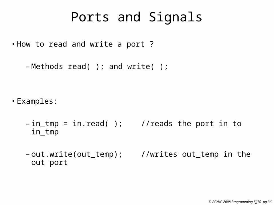
• How to read and write a port ?
– Methods read( ); and write( );
• Examples:
– in_tmp = in.read( ); //reads the port in to in_tmp
– out.write(out_temp); //writes out_temp in the out port

© PG/HC 2008 Programming 5JJ70 pg 37
Clocks
• Special object
• How to create ?
sc_clock clock_name (
“clock_label”, period, duty_ratio, offset, initial_value );
• Clock connection
f1.clk( clk_signal ); //where f1 is a module
2 12 22 32 42
sc_clock clock1 ("clock1", 20, 0.5, 2, true);
2 12 22 32 42
sc_clock clock1 ("clock1", 20, 0.5, 2, true);

© PG/HC 2008 Programming 5JJ70 pg 38
Data Types
•SystemC supports:–all C/C++ native types –plus specific SystemC types
•SystemC types –Types for systems modelling–2 values (‘0’,’1’)–4 values (‘0’,’1’,’Z’,’X’)–Arbitrary size integer (Signed/Unsigned)–Fixed point types

© PG/HC 2008 Programming 5JJ70 pg 39
SC_LOGIC type
• More general than bool, 4 values :– (‘0’ (false), ‘1’ (true), ‘X’ (undefined) , ‘Z’(high-impedance) )
• Assignment like bool– my_logic = ‘0’;– my_logic = ‘Z’;
• Simulation time bigger than bool
• Operators like bool
• Declaration– sc_logic my_logic;

© PG/HC 2008 Programming 5JJ70 pg 40
Fixed precision integers
• Used when arithmetic operations need fixed size arithmetic operands
• INT can be converted in UINT and vice-versa
• “int” in C++– The size depends on the machine– Faster in the simulation
• 1-64 bits integer in SystemC– sc_int<n> -- signed integer with n-bits – sc_uint<n> -- unsigned integer with n-bits

© PG/HC 2008 Programming 5JJ70 pg 41
Arbitrary precision integers
• Integer bigger than 64 bits– sc_bigint<n> – sc_biguint<n>
• More precision, slow simulation
• Can be used together with:– Integer C++– sc_int, sc_uint

© PG/HC 2008 Programming 5JJ70 pg 42
Other SystemC types
• Bit vector– sc_bv<n>– 2-valued vector (0/1)– Not used in arithmetics operations– Faster simulation than sc_lv
• Logic Vector– sc_lv<n>– Vector of the 4-valued sc_logic type
• Assignment operator (“=“)– my_vector = “XZ01”– Conversion between vector and integer (int or uint)– Assignment between sc_bv and sc_lv

© PG/HC 2008 Programming 5JJ70 pg 43
SystemC types overviewType Description
sc_logic Simple bit with 4 values(0/1/X/Z)
sc_int Signed Integer from 1-64 bits
sc_uint Unsigned Integer from 1-64 bits
sc_bigint Arbitrary size signed integer
sc_biguint Arbitrary size unsigned integer
sc_bv Arbitrary size 2-values vector
sc_lv Arbitrary size 4-values vector
sc_fixed templated signed fixed point
sc_ufixed templated unsigned fixed point
sc_fix untemplated signed fixed point
sc_ufix untemplated unsigned fixed point
See chapter 7 of the SystemC user manual for all details on Fixed Point
Types

© PG/HC 2008 Programming 5JJ70 pg 44
Examples of use of SystemC types
sc_bit y, sc_bv<8> x;y = x[6];
sc_bv<16> x, sc_bv<8> y;y = x.range(0,7);
sc_bv<64> databus, sc_logic result;result = databus.or_reduce();
sc_lv<32> bus2;cout << “bus = “ << bus2.to_string();
© PG/HC 2008 Programming 5JJ70 pg 45
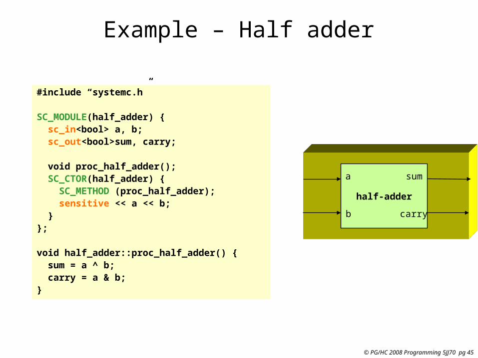
Example – Half adder
#include “systemc.h”
SC_MODULE(half_adder) { sc_in<bool> a, b; sc_out<bool>sum, carry;
void proc_half_adder(); SC_CTOR(half_adder) { SC_METHOD (proc_half_adder); sensitive << a << b; }};
void half_adder::proc_half_adder() { sum = a ^ b; carry = a & b;}
half-adder
a
b
sum
carry

© PG/HC 2008 Programming 5JJ70 pg 46
#include “half_adder.h”
SC_MODULE (full_adder) { sc_in<bool>a, b, carry_in; sc_out<bool>sum, carry_out;
sc_signal<bool>c1, s2, c2; void proc_or(); half_adder ha1(“ha1”), ha2(“ha2”); SC_CTOR(full_adder) { ha1.a(a); //by name connection ha1.b(b); ha1.sum(s1); ha1.carry(c1); h2(s1, carry_in, sum, c2) //by position connection SC_METHOD (proc_or); sensitive << c1 << c2; }};
Describing Hierarchy: Full adder
half-adder ha2
a
b
sum
carry
half-adder ha1
a
b
sum
carry
a
b
carry_in
sum

© PG/HC 2008 Programming 5JJ70 pg 47
Main --- Top Module
#Include “full_adder.h”#Include “pattern_gen.h”#include “monitor.h”
int sc_main(int argc, char* argv[]) { sc_signal<booL> t_a, t_b, t_cin, t_sum, t_cout;
full_adder f1(“Fulladder”);
//connect using positional association f1 << t_a << t_b << t_cin << t_sum << t_cout; pattern_gen pg_ptr = new
pattern_gen(“Generation”);
//connection using named association pg_ptr->d_a(t_a); pg_ptr->d_b(t_b); (*pg_ptr->d_cin(t_cin);
monitor mol(“Monitor”); mo1 << t_a << t_b << t_cin << t_sum << t_cout;
sc_start(100, SC_NS); return 0;}
Full_adder Monitor
Pattern_gen
a b c_in
sum
carry

© PG/HC 2008 Programming 5JJ70 pg 48
SystemC Highlights Summary (1)
• Support Hardware-Software Co-Design
• Interface in a C++ environment– Modules
• Container class includes hierarchical Entity and Processes
– Processes• Describe functionality, Event sensitivity
– Ports• Single-directional(in, out), Bi-directional(inout) mode
– Signals• Resolved, Unresolved signals
– Rich set of port and signal types– Rich set of data types
• All C/C++ types, 32/64-bit signed/unsigned, fixed-points, MVL, user defined

© PG/HC 2008 Programming 5JJ70 pg 49
SystemC Highlights Summary (2)
• Interface in a C++ environment (continued)– Clocks
• Special signal, Timekeeper of simulation and Multiple clocks, with arbitrary phase relationship
– Cycle-based simulation• High-Speed Cycle-Based simulation kernel
– Multiple abstraction levels• Untimed from high-level functional model to detailed
clock cycle accuracy RTL model– Communication Protocols– Debugging Supports
• Run-Time error check– Waveform Tracing