Embed Size (px)
Citation preview
1
Radiography: theory
Andrew Middleton and Janet Lang
Introduction; types of radiation, safety; generation and properties of X-rays; objects and X-rays
INTRODUCTION
The cartoon reproduced as Figure 1.1 was pub-lished in the magazine Life, within a few months ofRöntgen’s discovery of X-rays. It is a typical mani-festation of the excitement and public interest which
his work provoked. However imperfectly, the publicgrasped that Röntgen had discovered a new way of‘looking’ not just at objects but also through them.Of course, everyone knew that light passed throughtransparent and semi-transparent materials such asglass and paper; even a human hand gave a blood red
The new Roentgen photography‘Look pleasant, please.’
Figure 1.1. Contemporarycartoon from Life magazine,February 1896.
H6347-Ch01.qxd 7/7/05 1:02 PM Page 1
glow when held up to a strong light, but no detailscould be seen. Röntgen’s first published picturesshowed a hand, with the bones, flesh and a ring onone of the fingers, all clearly visible (Röntgen 1896).This was a totally new phenomenon. Within months,a beam of X-rays had been used to show up leadpellets accidentally shot into a New York lawyer’shand. The medical use of X-rays was launched.Archaeological applications also followed swiftly onRöntgen’s discovery: a paper published by Culin in1898 describes work carried out by Dr CharlesLeonard to produce radiographs of a Peruvianmummy and other artefacts from the University ofPennsylvania Museum (see Chapter 7).
Nowadays we are quite familiar with the medicaluses of X-rays; for instance, to image bones or toproduce dental or chest X-rays (or, more correctly,chest radiographs). These illustrate several of the keycharacteristics of radiography – the images are life-size, denser regions, such as bone, stand out fromsofter tissues as lighter areas on a conventional filmradiograph, and they contain information from thewhole depth of the subject, from the ribs through tothe spine on a chest radiograph. This means that allthe internal features of the patient (or any otherobject) are superimposed on top of one another. Thiscan sometimes result in radiographic images that are difficult to interpret. However, these difficultiesarising from the projection of a three-dimensionalsubject onto a two-dimensional radiograph can usuallybe overcome, for instance, by recording radiographsfrom different angles or by the use of more sophisti-cated techniques such as stereo-viewing, real-timeradiography or computed tomography (CT scanning)(see also Chapters 2 and 7).
Thus, radiography offers the possibility of obtain-ing a fascinating insight into the internal structure ofobjects as disparate as the human body and complexpieces of machinery. Given that this can be donewithout inflicting any damage to an inanimate object(the exposure of living tissues must always be care-fully controlled, see Box 1.2), it is easy to appreciatewhy radiography is being used increasingly in thestudy of archaeological and cultural objects. It iscapable of answering many questions about manu-facture, function and state of preservation, sometimesproviding information that is unobtainable by anyother technique. The purpose of this chapter is toprovide some technical background in order to indi-cate the scientific framework on which radiographicpractice rests. It is hoped that this will also help to indicate the general potential and limitations of
radiography in the study of cultural material, butthese aspects will be discussed more fully in relationto particular materials and classes of artefact in thechapters which follow.
RADIATION USED IN RADIOGRAPHY
In addition to X-rays, several other types of radi-ation are used in radiography to produce images,including electrons, neutrons and �-rays. Sources ofall four types of radiation are discussed briefly in thefollowing sections, although the main concern ofthis book is with the use of X-rays and also electronsfor certain specialist applications.
Electrons
Electrons useful to the radiographer may be derivedin two, rather different ways: from the decay ofradioactive substances, and from the impact of high-energy X-rays on a heavy metal such as lead.Electrons produced through radioactive decay areknown as �-rays or �-particles. Electrons arestrongly absorbed by all materials, including air, and have very limited penetration: even the moreenergetic, such as those emitted by strontium-90(2.25 MeV), are absorbed by 2–3 mm of aluminiumfoil. However, this lack of penetration can be usedto good effect to radiograph thin, low-density mate-rials. 14C (carbon-14 or radiocarbon) sources havecommonly been used. The radioactive 14C may beincorporated in a sheet of Perspex or aluminium foil,and in this form it is convenient and safe to handleprovided rubber gloves are worn. Sources are usuallysupplied with their own shielded containers, but a14C source can be stored in a secure lockable metalbox (e.g. a suitably sized cashbox) as it does notrequire lead shielding. �-radiography is ideal forimaging thin, flat materials such as paper, where agood contact can be maintained between the sheetor foil source and the subject (see Chapter 5).
Electrons are emitted when some heavy metals,like lead, gold or cadmium, are irradiated with ahigh-energy X-ray beam and, when generated inthis way, are utilized for two different radiographicmethods. The electrons emitted during the irradi-ation of a thin lead foil can be used to make electronradiographs of paper and similar materials, providingan alternative to the use of �-rays. This technique,electron (transmission) radiography, is described in
2 Radiography of Cultural Material
H6347-Ch01.qxd 7/7/05 1:02 PM Page 2
Chapter 5; an early account of the method wasgiven by Tasker and Towers in 1945. The secondapplication, electron emission radiography (some-times referred to as autoradiography), can be usedwhere an artist has employed paints or pigmentscontaining heavy metals: a high-energy X-ray beamcauses electron emission from the areas coveredwith the heavy metal paints or pigment. The imageof their distribution can be recorded on an X-rayfilm (see Chapter 5). This technique has also beenused to image other flat subjects such as the designson corroded medieval glass (Knight 1989) and apainting on copper (Bridgman et al. 1965). A thirduse of electrons occurs when lead screens areemployed as intensifiers, increasing the contrast rangeof radiographs.
Neutrons
The possibility of using a neutron beam in radiog-raphy was realized only 3 years after Chadwick dis-covered the neutron in 1932, by Kalman and Kuhn,using a small accelerator source in Berlin (Matfield1971). From the viewpoint of the radiographer of cultural material, the key property of thermal neu-trons (those most-commonly used for radiography)is that they are more strongly absorbed by organicmaterials than by many heavier materials. This is theconverse of X-rays and �-rays (see below) and offersthe possibility of revealing such details as the organicmaterials in scabbards or the fittings of iron blades(Masuzawa 1986; Tugrul 1990; Rant et al. 1995). Anexample illustrating the usefulness of this property ofneutrons is presented in Box 1.1 (see also Figure 3.3).
Radiography: theory 3
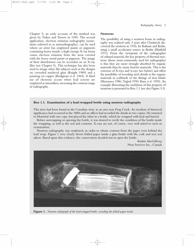
Box 1.1. Examination of a lead-wrapped bottle using neutron radiography
This item had been found in the Canadian west, in an area near Frog Creek. An incident of historicalsignificance had occurred in the 1880s and an officer had recorded the details in two copies. He returnedto Montréal with one copy, but placed the other in a bottle, which he wrapped with lead and buried.
Before unwrapping or opening the bottle, it was desired to verify the condition of the bottle insidethe wrapping, as well as the seal and contents. X-rays are not, of course, very well suited to such anexamination.
Neutron radiography was employed, in order to obtain contrast from the paper even behind thelead wrap. Figure 1 very clearly shows folded paper inside a glass bottle with the cork and wax sealaskew. Based upon this evidence, the conservators decided not to open the bottle.
Rankin MacGillivrayNray Services Inc., Canada
Figure 1. Neutron radiograph of the lead-wrapped bottle, revealing the folded paper inside.
H6347-Ch01.qxd 7/7/05 1:02 PM Page 3
However, the practical use of neutrons for radiog-raphy is inconvenient and is usually carried out at aspecialist facility. A disadvantage is that short-livedradioactivity may be induced in the object whichhas been irradiated, necessitating safe storage afterexposure.
�-rays
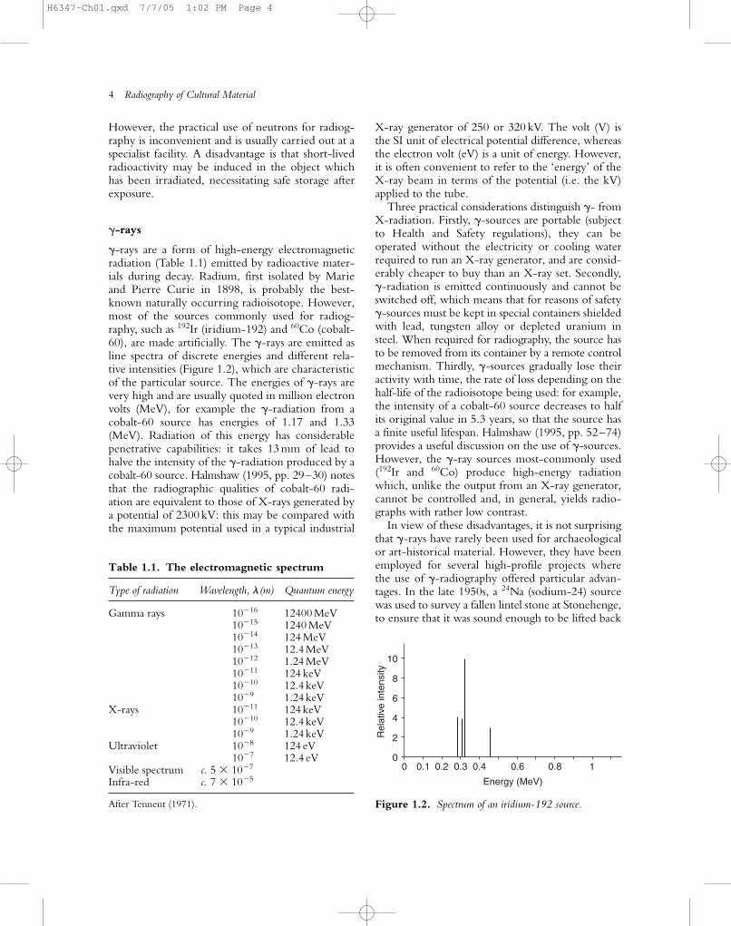
�-rays are a form of high-energy electromagneticradiation (Table 1.1) emitted by radioactive mater-ials during decay. Radium, first isolated by Marieand Pierre Curie in 1898, is probably the best-known naturally occurring radioisotope. However,most of the sources commonly used for radiog-raphy, such as 192Ir (iridium-192) and 60Co (cobalt-60), are made artificially. The �-rays are emitted asline spectra of discrete energies and different rela-tive intensities (Figure 1.2), which are characteristicof the particular source. The energies of �-rays arevery high and are usually quoted in million electronvolts (MeV), for example the �-radiation from acobalt-60 source has energies of 1.17 and 1.33(MeV). Radiation of this energy has considerablepenetrative capabilities: it takes 13 mm of lead tohalve the intensity of the �-radiation produced by acobalt-60 source. Halmshaw (1995, pp. 29–30) notesthat the radiographic qualities of cobalt-60 radi-ation are equivalent to those of X-rays generated bya potential of 2300 kV: this may be compared withthe maximum potential used in a typical industrial
X-ray generator of 250 or 320 kV. The volt (V) isthe SI unit of electrical potential difference, whereasthe electron volt (eV) is a unit of energy. However,it is often convenient to refer to the ‘energy’ of theX-ray beam in terms of the potential (i.e. the kV)applied to the tube.
Three practical considerations distinguish �- fromX-radiation. Firstly, �-sources are portable (subjectto Health and Safety regulations), they can be operated without the electricity or cooling waterrequired to run an X-ray generator, and are consid-erably cheaper to buy than an X-ray set. Secondly,�-radiation is emitted continuously and cannot beswitched off, which means that for reasons of safety�-sources must be kept in special containers shieldedwith lead, tungsten alloy or depleted uranium insteel. When required for radiography, the source hasto be removed from its container by a remote controlmechanism. Thirdly, �-sources gradually lose theiractivity with time, the rate of loss depending on thehalf-life of the radioisotope being used: for example,the intensity of a cobalt-60 source decreases to halfits original value in 5.3 years, so that the source hasa finite useful lifespan. Halmshaw (1995, pp. 52–74)provides a useful discussion on the use of �-sources.However, the �-ray sources most-commonly used(192Ir and 60Co) produce high-energy radiationwhich, unlike the output from an X-ray generator,cannot be controlled and, in general, yields radio-graphs with rather low contrast.
In view of these disadvantages, it is not surprisingthat �-rays have rarely been used for archaeologicalor art-historical material. However, they have beenemployed for several high-profile projects wherethe use of �-radiography offered particular advan-tages. In the late 1950s, a 24Na (sodium-24) sourcewas used to survey a fallen lintel stone at Stonehenge,to ensure that it was sound enough to be lifted back
4 Radiography of Cultural Material
00
2
4
6
8
10
0.1 0.2 0.3 0.4
Energy (MeV)
Rel
ativ
e in
tens
ity
0.6 0.8 1
Figure 1.2. Spectrum of an iridium-192 source.
Table 1.1. The electromagnetic spectrum
Type of radiation Wavelength, �(m) Quantum energy
Gamma rays 10�16 12400 MeV10�15 1240 MeV10�14 124 MeV10�13 12.4 MeV10�12 1.24 MeV10�11 124 keV10�10 12.4 keV10�9 1.24 keV
X-rays 10�11 124 keV10�10 12.4 keV10�9 1.24 keV
Ultraviolet 10�8 124 eV10�7 12.4 eV
Visible spectrum c. 5 � 10�7
Infra-red c. 7 � 10�5
After Tennent (1971).
H6347-Ch01.qxd 7/7/05 1:02 PM Page 4
on top of two upright stones (Hinsley 1959). Morerecent examples include a study of a bronze statueof Napoleon in the Brera Gallery in Milan, using an192Ir (iridium-192) source (Canova 1990), and partof an extensive study of the Chimera of Arrezzo(Massimi et al. 1991), using cobalt-60. An iridium-192 source was used also in the study of largeClassical bronzes carried out in connection withthe Fire of Hephaistos exhibition (Mattusch 1996)when a 300 kV X-ray set did not provide adequateradiographs.
X-rays
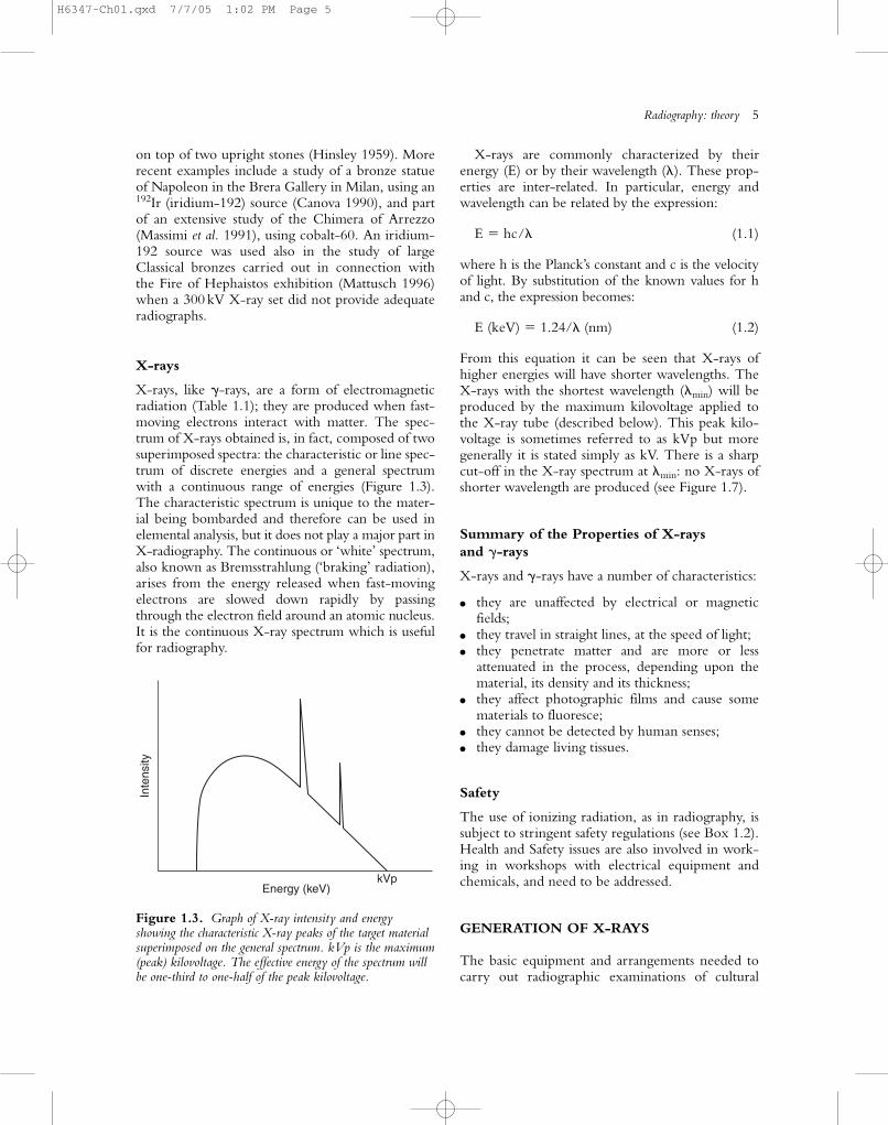
X-rays, like �-rays, are a form of electromagneticradiation (Table 1.1); they are produced when fast-moving electrons interact with matter. The spec-trum of X-rays obtained is, in fact, composed of twosuperimposed spectra: the characteristic or line spec-trum of discrete energies and a general spectrumwith a continuous range of energies (Figure 1.3).The characteristic spectrum is unique to the mater-ial being bombarded and therefore can be used inelemental analysis, but it does not play a major part inX-radiography. The continuous or ‘white’ spectrum,also known as Bremsstrahlung (‘braking’ radiation),arises from the energy released when fast-movingelectrons are slowed down rapidly by passingthrough the electron field around an atomic nucleus.It is the continuous X-ray spectrum which is usefulfor radiography.
X-rays are commonly characterized by theirenergy (E) or by their wavelength (�). These prop-erties are inter-related. In particular, energy andwavelength can be related by the expression:
E � hc/� (1.1)
where h is the Planck’s constant and c is the velocityof light. By substitution of the known values for hand c, the expression becomes:
E (keV) � 1.24/� (nm) (1.2)
From this equation it can be seen that X-rays ofhigher energies will have shorter wavelengths. TheX-rays with the shortest wavelength (�min) will beproduced by the maximum kilovoltage applied tothe X-ray tube (described below). This peak kilo-voltage is sometimes referred to as kVp but moregenerally it is stated simply as kV. There is a sharpcut-off in the X-ray spectrum at �min: no X-rays ofshorter wavelength are produced (see Figure 1.7).
Summary of the Properties of X-rays
and �-rays
X-rays and �-rays have a number of characteristics:
● they are unaffected by electrical or magneticfields;
● they travel in straight lines, at the speed of light;● they penetrate matter and are more or less
attenuated in the process, depending upon thematerial, its density and its thickness;
● they affect photographic films and cause somematerials to fluoresce;
● they cannot be detected by human senses;● they damage living tissues.
Safety
The use of ionizing radiation, as in radiography, issubject to stringent safety regulations (see Box 1.2).Health and Safety issues are also involved in work-ing in workshops with electrical equipment andchemicals, and need to be addressed.
GENERATION OF X-RAYS
The basic equipment and arrangements needed tocarry out radiographic examinations of cultural
Radiography: theory 5
kVpEnergy (keV)
Inte
nsity
Figure 1.3. Graph of X-ray intensity and energyshowing the characteristic X-ray peaks of the target materialsuperimposed on the general spectrum. kVp is the maximum(peak) kilovoltage. The effective energy of the spectrum willbe one-third to one-half of the peak kilovoltage.
H6347-Ch01.qxd 7/7/05 1:02 PM Page 5
material are shown schematically in Figure 1.4.Essentially, these comprise a source of X-rays, somemeans of supporting and perhaps manipulating theobject, and a means of observing and recording theradiographic image that results from directing the beam of X-rays through the object.
A modern X-ray set comprises several essentialparts which enable it to produce an X-ray beamreliably and on demand. At its heart is the X-raytube; also required are a control unit and a suitablecooling unit, the nature of which is dictated by thepower of the X-ray set.
X-ray Tubes
The X-ray tube shown diagrammatically in Figure1.5 has a number of necessary features:
1. The source of electrons is usually a wire fila-ment in the cathode, heated to incandescence
by a low-voltage electric current (measured inmilliamps, mA), causing it to emit a steady streamof electrons.
2. The potential applied between the cathode and the anode accelerates the electrons towardsthe target; the magnitude of the potential (oraccelerating voltage) is usually expressed askilovolts (kV).
3. The X-rays are produced at the target, which isembedded in the anode. The target is usuallymade of tungsten because it is an efficient sourceof high-energy X-rays. It is also a refractoryelement with a high melting point (3410˚C).This is an important consideration because most(typically about 99%) of the energy applied tothe tube is converted into heat, mainly at thetarget. Molybdenum is used as the target insome medical X-ray tubes as it produces agreater X-ray intensity at the lower energy end
6 Radiography of Cultural Material
Box 1.2. Health and safety
X-rays and �-rays, along with other forms of radiation including �-rays and neutrons, are hazardous tohealth and each country has its own regulations for the use of ionizing radiation. Readers are stronglyadvised to familiarize themselves with the current directives and regulations in the country where theyare working, always remembering to keep up to date with any changes which may be introduced. TheUK regulations are subject to European Union (EU) Directives and therefore similar to those of otherEU countries, but it is essential to check in case there are local differences. In the USA, the OSHA(Occupational Safety and Health Administration), part of the Department of Labor, is the relevant organ-ization. Standards for equipment in the USA are set up by the US Food and Drug Administration Centrefor Devices and Radiology Health (21 CFR-1020.40). The Internet is a useful source of information.
Radiographic work in the UK is currently governed by the Ionizing Radiation Regulations 1999 SI 1999 3232 which are based on a revision of the EU Basic Safety Statute. The Radioactive Substances Act 1993 may also apply. The Regulations are Statutory Instruments and therefore have legal status. TheRegulations lay down the rules under which radiography can be carried out and cover the responsibilitiesof employers and employees. The provisions must be obeyed by all those who are involved in radiography,even as visitors. They are administered by the Health and Safety Executive (HSE) which is part of theDepartment of the Environment, Transport and the Regions (1999). http://www.legislation.hmso.gov.uk/
The Regulations are set out and their implementation is explained in the Approved Code of Practice. Thisdocument also has legal status and gives practical advice on how to comply with the law.
The Regulations and Code cover all aspects of the use of ionizing radiation. This includes the initiation,arrangement and monitoring of equipment and facilities, the appointment of Radiation ProtectionAdvisors (RPAs), the provision of Local Rules, dose rates, the monitoring of staff exposure to radiation,the responsibilities and duties of management and operating staff, training and record keeping. It isimportant to remember that the appointed RPA should be informed and consulted about changes inworking practice or equipment or the undertaking of any new work.
The disposal of waste (e.g. radiographic/photographic chemicals and lead, as well as radioactivesources) is also a health and safety matter and must be dealt with according to the current safety regula-tions, which will also include directives on all matters relating to health and safety, including, for exam-ple, working in reduced lighting (i.e. under safelights or in complete darkness).
H6347-Ch01.qxd 7/7/05 1:02 PM Page 6

Radiography: theory 7
X-ray source
Subject Recordingmedium
Film
Figure 1.4. Schematic representation of the radiographic process, with a radiation source, a subject and a means of recordingthe image (e.g. film).
Figure 1.5. Cut-away diagram of a typical constant potential X-ray tube.
H6347-Ch01.qxd 7/7/05 1:02 PM Page 7
of the spectrum. The target is usually embeddedin a good conductor of heat (copper), which iscooled by oil circulating through it.
4. A vacuum surrounds the filament and target,which allows the stream of electrons to be sustained.
5. The exit window for the X-ray beam is oftenmade of beryllium which is a light element; thisminimizes absorption of the X-ray beam as itpasses through the window, which is particularlyimportant when using low-energy X-rays.
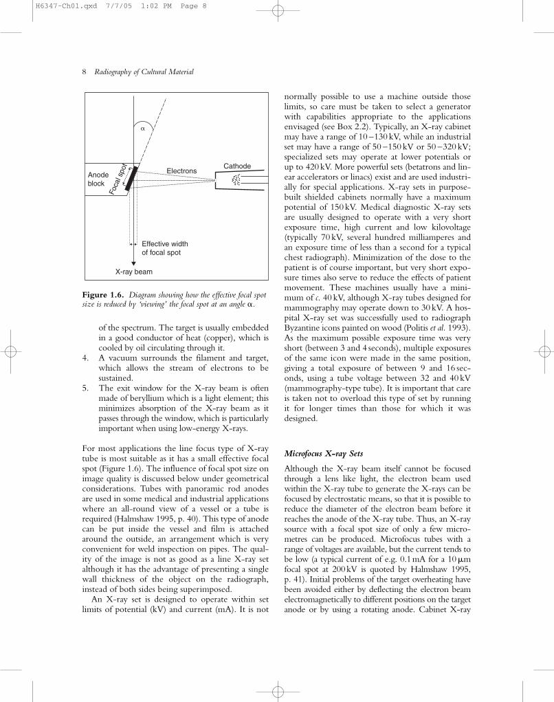
For most applications the line focus type of X-raytube is most suitable as it has a small effective focalspot (Figure 1.6). The influence of focal spot size onimage quality is discussed below under geometricalconsiderations. Tubes with panoramic rod anodesare used in some medical and industrial applicationswhere an all-round view of a vessel or a tube isrequired (Halmshaw 1995, p. 40). This type of anodecan be put inside the vessel and film is attachedaround the outside, an arrangement which is veryconvenient for weld inspection on pipes. The qual-ity of the image is not as good as a line X-ray setalthough it has the advantage of presenting a singlewall thickness of the object on the radiograph,instead of both sides being superimposed.
An X-ray set is designed to operate within setlimits of potential (kV) and current (mA). It is not
normally possible to use a machine outside thoselimits, so care must be taken to select a generatorwith capabilities appropriate to the applicationsenvisaged (see Box 2.2). Typically, an X-ray cabinetmay have a range of 10 –130 kV, while an industrialset may have a range of 50 –150 kV or 50 –320 kV;specialized sets may operate at lower potentials orup to 420 kV. More powerful sets (betatrons and lin-ear accelerators or linacs) exist and are used industri-ally for special applications. X-ray sets in purpose-built shielded cabinets normally have a maximumpotential of 150 kV. Medical diagnostic X-ray setsare usually designed to operate with a very shortexposure time, high current and low kilovoltage(typically 70 kV, several hundred milliamperes andan exposure time of less than a second for a typicalchest radiograph). Minimization of the dose to thepatient is of course important, but very short expo-sure times also serve to reduce the effects of patientmovement. These machines usually have a mini-mum of c. 40 kV, although X-ray tubes designed formammography may operate down to 30 kV. A hos-pital X-ray set was successfully used to radiographByzantine icons painted on wood (Politis et al. 1993).As the maximum possible exposure time was veryshort (between 3 and 4 seconds), multiple exposuresof the same icon were made in the same position,giving a total exposure of between 9 and 16 sec-onds, using a tube voltage between 32 and 40 kV(mammography-type tube). It is important that careis taken not to overload this type of set by running it for longer times than those for which it wasdesigned.
Microfocus X-ray Sets
Although the X-ray beam itself cannot be focusedthrough a lens like light, the electron beam usedwithin the X-ray tube to generate the X-rays can befocused by electrostatic means, so that it is possible toreduce the diameter of the electron beam before itreaches the anode of the X-ray tube. Thus, an X-raysource with a focal spot size of only a few micro-metres can be produced. Microfocus tubes with arange of voltages are available, but the current tends tobe low (a typical current of e.g. 0.1mA for a 10�mfocal spot at 200kV is quoted by Halmshaw 1995, p. 41). Initial problems of the target overheating havebeen avoided either by deflecting the electron beamelectromagnetically to different positions on the targetanode or by using a rotating anode. Cabinet X-ray
8 Radiography of Cultural Material
X-ray beam
Effective widthof focal spot
Electrons
�
CathodeAnodeblock
Foca
l spo
t
Figure 1.6. Diagram showing how the effective focal spotsize is reduced by ‘viewing’ the focal spot at an angle �.
H6347-Ch01.qxd 7/7/05 1:02 PM Page 8
sets with microfocus tubes offering a focal spot size of70 �m and energy range of 10 –110kVp are available(e.g. Faxitron). The principal advantage of microfo-cus tubes is that enlarged images can be formed withnegligible loss of sharpness; they also offer the possibil-ity of reducing the effect of internally generated scat-ter (see below) by leaving a small gap (say 20mm)between the object and film, again without significantloss of sharpness. The use of the microfocus tube ismentioned again in Chapter 2 (in the section onGeometric considerations).
Characteristics of the X-ray Beam
The characteristics of the X-ray beam, such as itsintensity and penetrative power, can be controlledby varying the cathode current and the tube voltage(potential). These characteristics, along with thefocal spot size and other factors, affect image quality;this is discussed more fully later in the chapter. Thecurrent (mA) controls the intensity of the radiation;intensity is defined as the energy per unit area perunit time. The potential (kV) applied to the X-raytube controls the maximum energy and the energydistribution of the X-rays and therefore determinesthe penetrative power of the beam.
Changing the Current
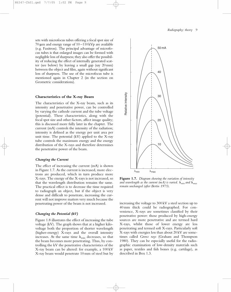
The effect of increasing the current (mA) is shownin Figure 1.7. As the current is increased, more elec-trons are produced, which in turn produce more X-rays. The energy of the X-rays is not increased, sothat the wavelength distribution remains the same.The practical effect is to decrease the time requiredto radiograph an object, but if the object is verydense and difficult to penetrate, increasing the cur-rent will not improve matters very much because thepenetrating power of the beam is not increased.
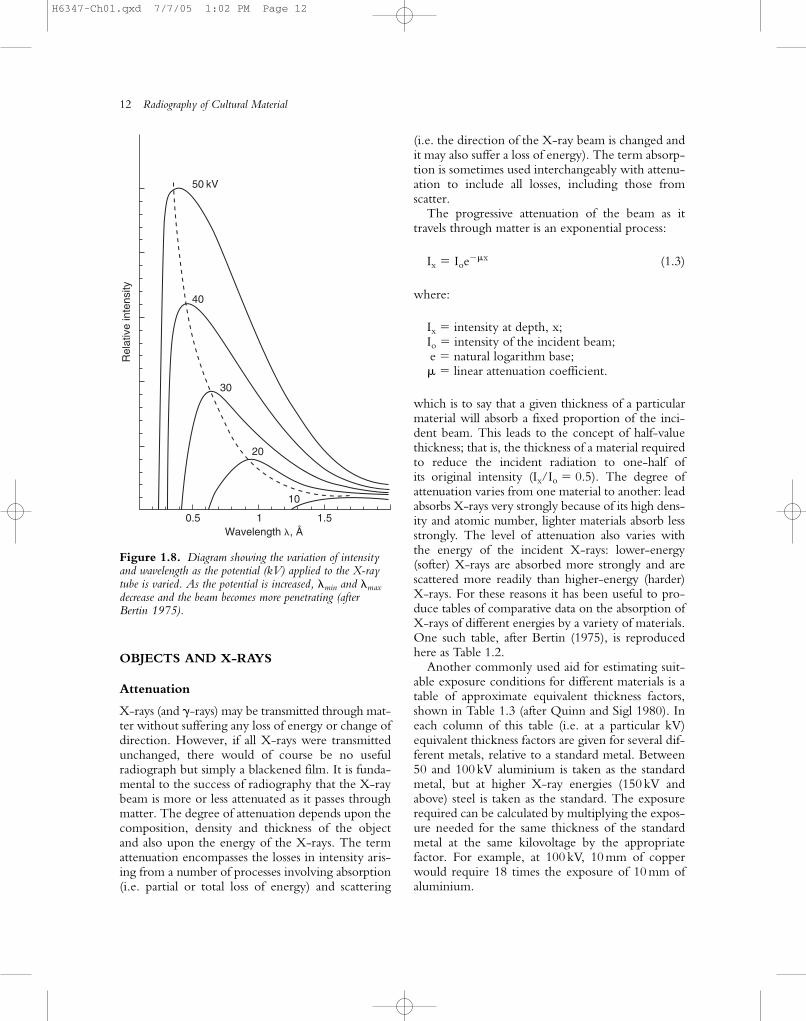
Changing the Potential (kV)
Figure 1.8 illustrates the effect of increasing the tubevoltage (kV). The graph shows that at a higher kilo-voltage both the proportion of shorter wavelength(higher-energy) X-rays and the overall intensityincreases. At the same time �min decreases, so thatthe beam becomes more penetrating. Thus, by con-trolling the kV the penetrative characteristics of theX-ray beam can be altered: for example, a 100 kVX-ray beam would penetrate 10 mm of steel but by
increasing the voltage to 300 kV a steel section up to40 mm thick could be radiographed. For con-venience, X-rays are sometimes classified by theirpenetrative power: those produced by high-energysources are more penetrative and are termed hard X-rays, whilst those of lower energy are less penetrating and termed soft X-rays. Particularly soft X-rays with energies less than about 20kV are some-times called Grenz rays (Graham and Thompson1980). They can be especially useful for the radio-graphic examination of low-density materials suchas paper, textiles and fish bones (e.g. cartilage), asdescribed in Box 1.3.
Radiography: theory 9
�min �max
50 mA
40
30
Rel
ativ
e in
tens
ity
20
10
Figure 1.7. Diagram showing the variation of intensityand wavelength as the current (mA) is varied. �min and �max
remain unchanged (after Bertin 1975).
H6347-Ch01.qxd 7/7/05 1:02 PM Page 9
10 Radiography of Cultural Material
Box 1.3. Textiles and organic artefacts
When exploring paint layers on canvas (Chapter 6) or X-raying mummies (Chapter 7), the textilesincorporated in them are often considered as an incidental component or even as a hindrance to gain-ing a clear image of the intended subject. However, suitably filtered, low-energy X-rays can be usedto produce remarkably detailed images of organic objects including textile artefacts (Brooks andO’Connor 2005). The Turin shroud has been recorded and explored using radiography (Mottern et al.1980) and components of upholstery have also been investigated (Gill and Doyal 2001). Nevertheless,textiles have generally not been the primary subjects of radiographic studies. Radiographs can identifyhidden aspects such as seaming, fillings, repairs, areas of degradation and structural supports or moresubtle details such as internal stitching threads and variations in weave structure. Technological featuressuch as differential metal weightings in woven silk textiles may also been mapped (Brooks et al. 1996).
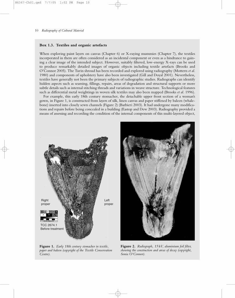
For example, this early 18th century stomacher, the detachable upper front section of a woman’sgown, in Figure 1, is constructed from layers of silk, linen canvas and paper stiffened by baleen (whale-bone) inserted into closely sewn channels (Figure 2) (Barbieri 2003). It had undergone many modifica-tions and repairs before being concealed in a building (Eastop and Dew 2003). Radiography provided ameans of assessing and recording the condition of the internal components of this multi-layered object,
Rightproper
Leftproper
TCC 2674.1 Before treatment
Figure 1. Early 18th century stomacher in textile,paper and baleen (copyright of the Textile ConservationCentre).
Figure 2. Radiograph, 15 kV, aluminium foil filter,showing the construction and areas of decay (copyright,Sonia O’Connor).
H6347-Ch01.qxd 7/7/05 1:02 PM Page 10
Radiography: theory 11
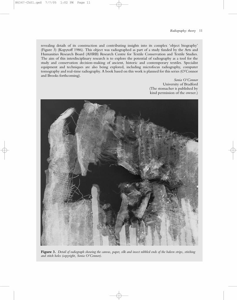
revealing details of its construction and contributing insights into its complex ‘object biography’(Figure 3) (Kopytoff 1986). This object was radiographed as part of a study funded by the Arts andHumanities Research Board (AHRB) Research Centre for Textile Conservation and Textile Studies.The aim of this interdisciplinary research is to explore the potential of radiography as a tool for thestudy and conservation decision-making of ancient, historic and contemporary textiles. Specialistequipment and techniques are also being explored, including microfocus radiography, computertomography and real-time radiography. A book based on this work is planned for this series (O’Connorand Brooks forthcoming).
Sonia O’ConnorUniversity of Bradford
(The stomacher is published by kind permission of the owner.)
Figure 3. Detail of radiograph showing the canvas, paper, silk and insect nibbled ends of the baleen strips, stitchingand stitch holes (copyright, Sonia O’Connor).
H6347-Ch01.qxd 7/7/05 1:02 PM Page 11
12 Radiography of Cultural Material
OBJECTS AND X-RAYS
Attenuation
X-rays (and �-rays) may be transmitted through mat-ter without suffering any loss of energy or change ofdirection. However, if all X-rays were transmittedunchanged, there would of course be no usefulradiograph but simply a blackened film. It is funda-mental to the success of radiography that the X-raybeam is more or less attenuated as it passes throughmatter. The degree of attenuation depends upon thecomposition, density and thickness of the objectand also upon the energy of the X-rays. The termattenuation encompasses the losses in intensity aris-ing from a number of processes involving absorption(i.e. partial or total loss of energy) and scattering
(i.e. the direction of the X-ray beam is changed andit may also suffer a loss of energy). The term absorp-tion is sometimes used interchangeably with attenu-ation to include all losses, including those fromscatter.
The progressive attenuation of the beam as ittravels through matter is an exponential process:
Ix � Ioe��x (1.3)
where:
Ix � intensity at depth, x;Io � intensity of the incident beam;e � natural logarithm base;� � linear attenuation coefficient.
which is to say that a given thickness of a particularmaterial will absorb a fixed proportion of the inci-dent beam. This leads to the concept of half-valuethickness; that is, the thickness of a material requiredto reduce the incident radiation to one-half of its original intensity (Ix/Io � 0.5). The degree ofattenuation varies from one material to another: leadabsorbs X-rays very strongly because of its high dens-ity and atomic number, lighter materials absorb lessstrongly. The level of attenuation also varies withthe energy of the incident X-rays: lower-energy(softer) X-rays are absorbed more strongly and arescattered more readily than higher-energy (harder)X-rays. For these reasons it has been useful to pro-duce tables of comparative data on the absorption ofX-rays of different energies by a variety of materials.One such table, after Bertin (1975), is reproducedhere as Table 1.2.
Another commonly used aid for estimating suit-able exposure conditions for different materials is atable of approximate equivalent thickness factors,shown in Table 1.3 (after Quinn and Sigl 1980). Ineach column of this table (i.e. at a particular kV)equivalent thickness factors are given for several dif-ferent metals, relative to a standard metal. Between50 and 100 kV aluminium is taken as the standardmetal, but at higher X-ray energies (150 kV andabove) steel is taken as the standard. The exposurerequired can be calculated by multiplying the expos-ure needed for the same thickness of the standardmetal at the same kilovoltage by the appropriate factor. For example, at 100 kV, 10 mm of copperwould require 18 times the exposure of 10 mm ofaluminium.
0.5 1Wavelength �, Å
Rel
ativ
e in
tens
ity
1.5
50 kV
40
30
20
10
Figure 1.8. Diagram showing the variation of intensityand wavelength as the potential (kV) applied to the X-raytube is varied. As the potential is increased, �min and �max
decrease and the beam becomes more penetrating (after Bertin 1975).
H6347-Ch01.qxd 7/7/05 1:02 PM Page 12
Scatter
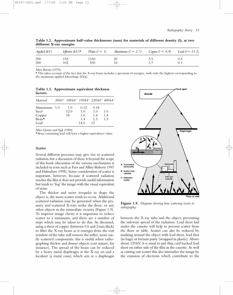
Several different processes may give rise to scatteredradiation but a discussion of these is beyond the scopeof this book (discussion of the various mechanisms isincluded in texts such as Farr and Allisy-Roberts 1997and Halmshaw 1995). Some consideration of scatter isimportant, however, because if scattered radiationreaches the film it does not provide useful informationbut tends to ‘fog’ the image with the visual equivalentof noise.
The thicker and more irregular in shape theobject is, the more scatter tends to occur. Additionalscattered radiation may be generated when the pri-mary and scattered X-rays strike the floor, or anyother objects in the immediate vicinity (Figure 1.9).To improve image clarity it is important to reducescatter to a minimum, and there are a number ofsteps which may be taken to do this. As discussed,using a sheet of copper (between 0.6 and 2mm thick)to filter the X-ray beam as it emerges from the exitwindow of the tube will remove the softer, more eas-ily scattered components: this is useful when radio-graphing thicker and denser objects (cast statues, forinstance). The spread of the beam can be reducedby a heavy metal diaphragm at the X-ray set and alocalizer (a metal cone) which acts as a diaphragm
between the X-ray tube and the object, preventingthe sideways spread of the radiation. Lead sheet laidunder the cassette will help to prevent scatter fromthe floor or table. Scatter can also be reduced bymasking around the object with lead sheet, lead shot(in bags) or barium putty (wrapped in plastic). Aboveabout 120kV, it is usual to put thin card backed leadsheet on either side of the film in the cassette. As wellas cutting out scatter this also intensifies the image bythe emission of electrons which contribute to the
Radiography: theory 13
Table 1.3. Approximate equivalent thicknessfactors
Material 50 kV 100 kV 150 kV 220 kV 400 kV
Aluminium 1.0 1.0 0.12 0.18Steel 12.0 1.0 1.0 1.0Copper 18 1.6 1.4 1.4Brass* 1.4 1.3 1.3Lead 14.0 12
After Quinn and Sigl (1980).*Brass containing lead will have a higher equivalence value.
Figure 1.9. Diagram showing how scattering occurs inradiography.
Table 1.2. Approximate half-value thicknesses (mm) for materials of different density (l), at twodifferent X-ray energies
Applied (kV) Effective (kV)* Water ( l � 1) Aluminium ( l � 2.7) Copper ( l � 8.9) Lead (l � 11.2)
300 154 1160 20 3.9 0.4200 102 530 16 1.7 0.1
After Bertin (1975).* This takes account of the fact that the X-ray beam includes a spectrum of energies, with only the highest corresponding tothe maximum applied kilovoltage (kVp).
H6347-Ch01.qxd 7/7/05 1:02 PM Page 13
14 Radiography of Cultural Material
l
λ
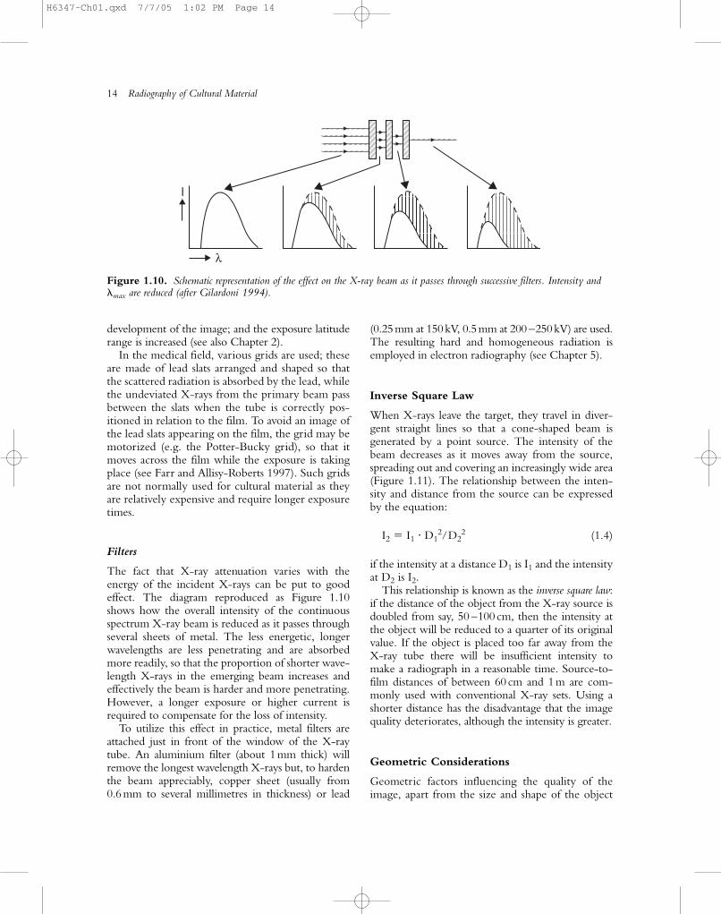
Figure 1.10. Schematic representation of the effect on the X-ray beam as it passes through successive filters. Intensity and�max are reduced (after Gilardoni 1994).
development of the image; and the exposure latituderange is increased (see also Chapter 2).
In the medical field, various grids are used; theseare made of lead slats arranged and shaped so thatthe scattered radiation is absorbed by the lead, whilethe undeviated X-rays from the primary beam passbetween the slats when the tube is correctly pos-itioned in relation to the film. To avoid an image ofthe lead slats appearing on the film, the grid may bemotorized (e.g. the Potter-Bucky grid), so that itmoves across the film while the exposure is takingplace (see Farr and Allisy-Roberts 1997). Such gridsare not normally used for cultural material as theyare relatively expensive and require longer exposuretimes.
Filters
The fact that X-ray attenuation varies with theenergy of the incident X-rays can be put to goodeffect. The diagram reproduced as Figure 1.10shows how the overall intensity of the continuousspectrum X-ray beam is reduced as it passes throughseveral sheets of metal. The less energetic, longerwavelengths are less penetrating and are absorbedmore readily, so that the proportion of shorter wave-length X-rays in the emerging beam increases andeffectively the beam is harder and more penetrating.However, a longer exposure or higher current isrequired to compensate for the loss of intensity.
To utilize this effect in practice, metal filters areattached just in front of the window of the X-raytube. An aluminium filter (about 1mm thick) willremove the longest wavelength X-rays but, to hardenthe beam appreciably, copper sheet (usually from0.6mm to several millimetres in thickness) or lead
(0.25mm at 150kV, 0.5mm at 200 –250kV) are used.The resulting hard and homogeneous radiation isemployed in electron radiography (see Chapter 5).
Inverse Square Law
When X-rays leave the target, they travel in diver-gent straight lines so that a cone-shaped beam isgenerated by a point source. The intensity of thebeam decreases as it moves away from the source,spreading out and covering an increasingly wide area(Figure 1.11). The relationship between the inten-sity and distance from the source can be expressedby the equation:
I2 � I1 D12/D2
2 (1.4)
if the intensity at a distance D1 is I1 and the intensityat D2 is I2.
This relationship is known as the inverse square law:if the distance of the object from the X-ray source isdoubled from say, 50 –100cm, then the intensity atthe object will be reduced to a quarter of its originalvalue. If the object is placed too far away from the X-ray tube there will be insufficient intensity tomake a radiograph in a reasonable time. Source-to-film distances of between 60 cm and 1m are com-monly used with conventional X-ray sets. Using ashorter distance has the disadvantage that the imagequality deteriorates, although the intensity is greater.
Geometric Considerations
Geometric factors influencing the quality of theimage, apart from the size and shape of the object
H6347-Ch01.qxd 7/7/05 1:02 PM Page 14
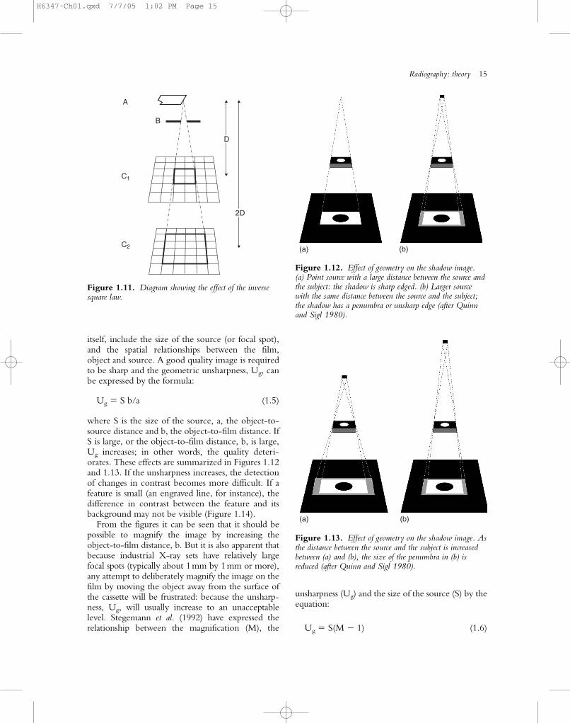
itself, include the size of the source (or focal spot),and the spatial relationships between the film,object and source. A good quality image is requiredto be sharp and the geometric unsharpness, Ug, canbe expressed by the formula:
Ug � S b/a (1.5)
where S is the size of the source, a, the object-to-source distance and b, the object-to-film distance. IfS is large, or the object-to-film distance, b, is large,Ug increases; in other words, the quality deteri-orates. These effects are summarized in Figures 1.12and 1.13. If the unsharpness increases, the detectionof changes in contrast becomes more difficult. If afeature is small (an engraved line, for instance), thedifference in contrast between the feature and itsbackground may not be visible (Figure 1.14).
From the figures it can be seen that it should bepossible to magnify the image by increasing theobject-to-film distance, b. But it is also apparent thatbecause industrial X-ray sets have relatively largefocal spots (typically about 1mm by 1mm or more),any attempt to deliberately magnify the image on thefilm by moving the object away from the surface ofthe cassette will be frustrated: because the unsharp-ness, Ug, will usually increase to an unacceptablelevel. Stegemann et al. (1992) have expressed therelationship between the magnification (M), the
unsharpness (Ug) and the size of the source (S) by theequation:
Ug � S(M � 1) (1.6)
Radiography: theory 15
2D
D
A
B
C1
C2
Figure 1.11. Diagram showing the effect of the inversesquare law.
(a) (b)
Figure 1.12. Effect of geometry on the shadow image. (a) Point source with a large distance between the source andthe subject: the shadow is sharp edged. (b) Larger sourcewith the same distance between the source and the subject;the shadow has a penumbra or unsharp edge (after Quinnand Sigl 1980).
(a) (b)
Figure 1.13. Effect of geometry on the shadow image. Asthe distance between the source and the subject is increasedbetween (a) and (b), the size of the penumbra in (b) isreduced (after Quinn and Sigl 1980).
H6347-Ch01.qxd 7/7/05 1:02 PM Page 15
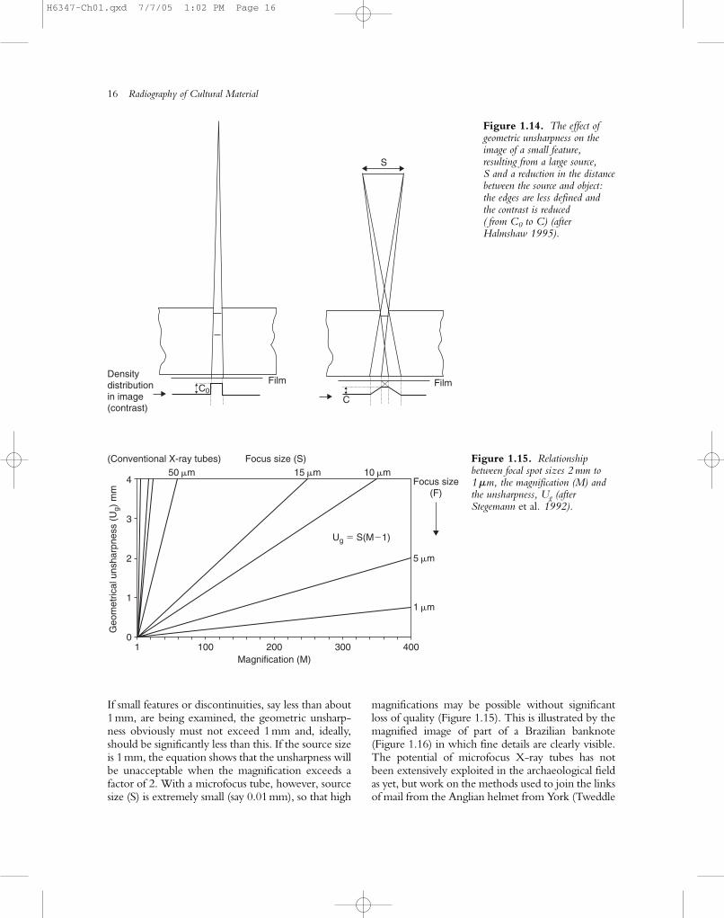
If small features or discontinuities, say less than about1mm, are being examined, the geometric unsharp-ness obviously must not exceed 1mm and, ideally,should be significantly less than this. If the source sizeis 1mm, the equation shows that the unsharpness willbe unacceptable when the magnification exceeds afactor of 2. With a microfocus tube, however, sourcesize (S) is extremely small (say 0.01mm), so that high
magnifications may be possible without significantloss of quality (Figure 1.15). This is illustrated by themagnified image of part of a Brazilian banknote(Figure 1.16) in which fine details are clearly visible.The potential of microfocus X-ray tubes has notbeen extensively exploited in the archaeological fieldas yet, but work on the methods used to join the linksof mail from the Anglian helmet from York (Tweddle
16 Radiography of Cultural Material
50 �m4
3
2
1
1 100 200Magnification (M)
Focus size (S)(Conventional X-ray tubes)
Geo
met
rical
uns
harp
ness
(U
g) m
m
300 4000
15 �m 10 �m
5 �m
Ug � S(M�1)
1 �m
Focus size(F)
Figure 1.15. Relationshipbetween focal spot sizes 2 mm to1 �m, the magnification (M) andthe unsharpness, Ug (afterStegemann et al. 1992).
Densitydistributionin image(contrast)
C
S
FilmFilmC0
Figure 1.14. The effect ofgeometric unsharpness on theimage of a small feature,resulting from a large source, S and a reduction in the distancebetween the source and object:the edges are less defined and the contrast is reduced ( from C0 to C) (afterHalmshaw 1995).
H6347-Ch01.qxd 7/7/05 1:02 PM Page 16
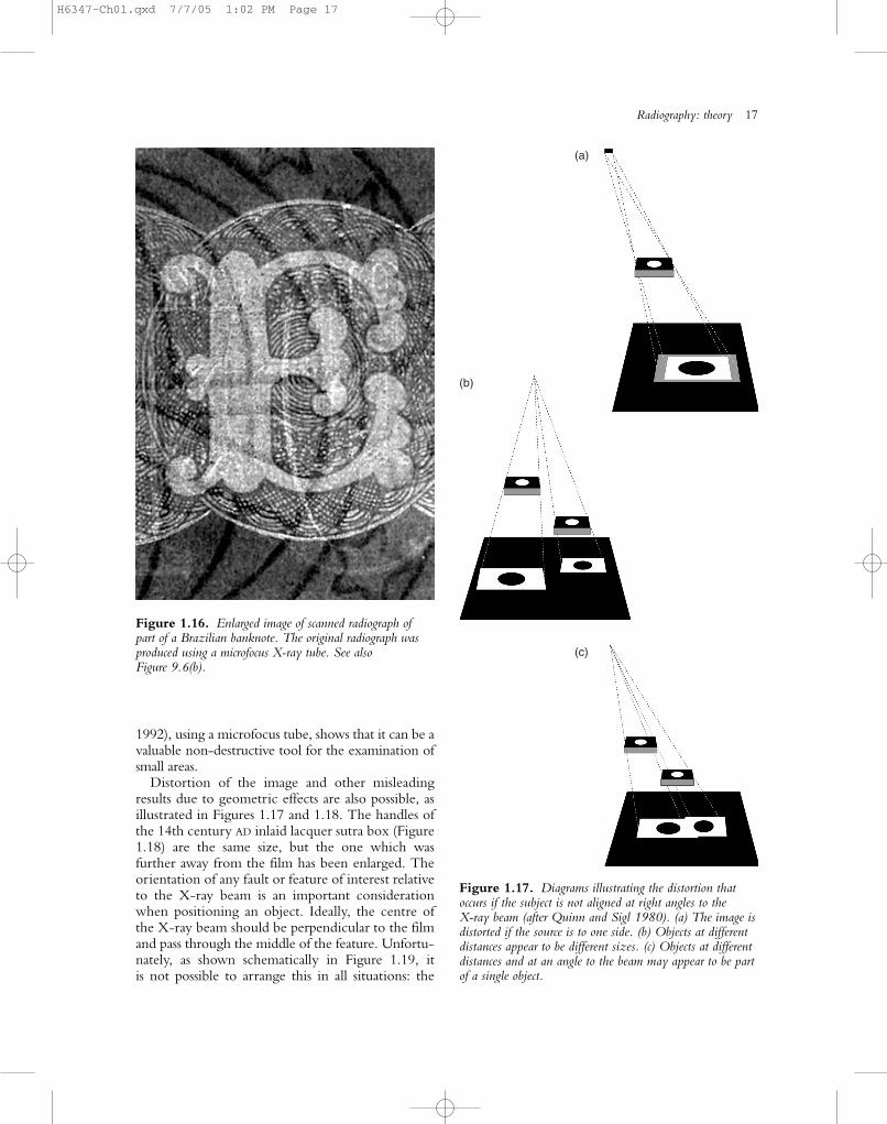
1992), using a microfocus tube, shows that it can be avaluable non-destructive tool for the examination ofsmall areas.
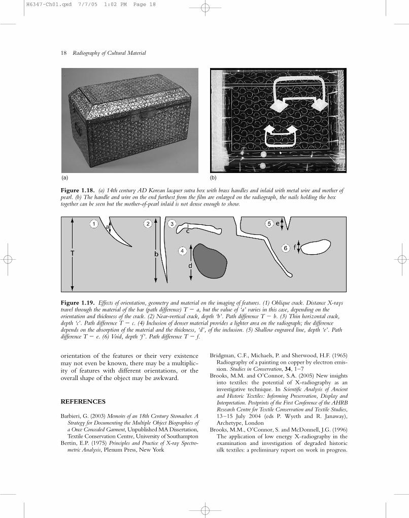
Distortion of the image and other misleadingresults due to geometric effects are also possible, asillustrated in Figures 1.17 and 1.18. The handles ofthe 14th century AD inlaid lacquer sutra box (Figure1.18) are the same size, but the one which was further away from the film has been enlarged. Theorientation of any fault or feature of interest relativeto the X-ray beam is an important considerationwhen positioning an object. Ideally, the centre ofthe X-ray beam should be perpendicular to the filmand pass through the middle of the feature. Unfortu-nately, as shown schematically in Figure 1.19, it is not possible to arrange this in all situations: the
Radiography: theory 17
Figure 1.16. Enlarged image of scanned radiograph of part of a Brazilian banknote. The original radiograph wasproduced using a microfocus X-ray tube. See also Figure 9.6(b).
(a)
(c)
(b)
Figure 1.17. Diagrams illustrating the distortion thatoccurs if the subject is not aligned at right angles to the X-ray beam (after Quinn and Sigl 1980). (a) The image isdistorted if the source is to one side. (b) Objects at differentdistances appear to be different sizes. (c) Objects at differentdistances and at an angle to the beam may appear to be partof a single object.
H6347-Ch01.qxd 7/7/05 1:02 PM Page 17
18 Radiography of Cultural Material
orientation of the features or their very existencemay not even be known, there may be a multiplic-ity of features with different orientations, or theoverall shape of the object may be awkward.
REFERENCES
Barbieri, G. (2003) Memoirs of an 18th Century Stomacher. AStrategy for Documenting the Multiple Object Biographies ofa Once Concealed Garment, Unpublished MA Dissertation,Textile Conservation Centre, University of Southampton
Bertin, E.P. (1975) Principles and Practice of X-ray Spectro-metric Analysis, Plenum Press, New York
Bridgman, C.F., Michaels, P. and Sherwood, H.F. (1965)Radiography of a painting on copper by electron emis-sion. Studies in Conservation, 34, 1–7
Brooks, M.M. and O’Connor, S.A. (2005) New insightsinto textiles: the potential of X-radiography as aninvestigative technique. In Scientific Analysis of Ancientand Historic Textiles: Informing Preservation, Display andInterpretation. Postprints of the First Conference of the AHRBResearch Centre for Textile Conservation and Textile Studies,13–15 July 2004 (eds P. Wyeth and R. Janaway),Archetype, London
Brooks, M.M., O’Connor, S. and McDonnell, J.G. (1996)The application of low energy X-radiography in theexamination and investigation of degraded historic silk textiles: a preliminary report on work in progress.
(a) (b)
Figure 1.18. (a) 14th century AD Korean lacquer sutra box with brass handles and inlaid with metal wire and mother ofpearl. (b) The handle and wire on the end furthest from the film are enlarged on the radiograph, the nails holding the boxtogether can be seen but the mother-of-pearl inlaid is not dense enough to show.
Figure 1.19. Effects of orientation, geometry and material on the imaging of features. (1) Oblique crack. Distance X-raystravel through the material of the bar (path difference) T � a, but the value of ‘a’ varies in this case, depending on theorientation and thickness of the crack. (2) Near-vertical crack, depth ‘b’. Path difference T � b. (3) Thin horizontal crack,depth ‘c’. Path difference T � c. (4) Inclusion of denser material provides a lighter area on the radiograph; the differencedepends on the absorption of the material and the thickness, ‘d’, of the inclusion. (5) Shallow engraved line, depth ‘e’. Pathdifference T � e. (6) Void, depth ‘f ’. Path difference T � f.
H6347-Ch01.qxd 7/7/05 1:02 PM Page 18
In Preprints, 11th ICOM Triennial Meeting Committee forConservation (ed. J. Bridgland), James & James, London,pp. 670 –9
Canova, A. (1990) Technology for Culture (eds D. Maurizioand G. Giolj), De Luca Edizioni d’Arte, Rome, pp. 94–5
Culin, S. (1898) An Archaeological Application of the RöntgenRays. Bulletin No. 4, Free Museum of Science andArt, University of Pennsylvania, Philadelphia, p. 183
Eastop, D. and C. Dew. (2003) Secret agents: deliberatelyconcealed garments as symbolic textiles. In NATCCBiannual Conference 2003: The Conservation of Flags andother Symbolic Textiles (ed. J. Vuori), NATCC, Albany,USA, pp. 5–15
Farr, R.F. and Allisy-Roberts, P.J. (1997) Physics forMedical Imaging, Saunders, New York
Gilardoni, A. (1994) X-rays in Art, Gilardoni SpA,Mandello Lario, Lecco
Gill, K. and Doyal, S. (2001) A brief object record: theBrooklyn Museum of Art easy chair. In Upholstery Con-servation: Principles and Practice (eds K. Gill and D. Eastop),Butterworth Heinemann, Oxford, pp. 186 –92.
Graham, D. and Thompson, J. (1980) Grenz Rays,Pergamon, Oxford
Halmshaw, R. (1995) Industrial Radiology (2nd edition),Chapman & Hall, London
Hinsley, J.F. (1959) Non-destructive Testing, Vol. 2,Macdonald & Evans, London
Knight, B. (1989) Imaging the designs on corrodedmedieval window glass by beta-backscattered radiog-raphy. Studies in Conservation, 34, 207–11
Kopytoff, I. (1986) The cultural biography of things:commoditization as process. In The Social Life of Things.Commodities on Cultural Perspective (ed A. Appadurai),Cambridge University Press, Cambridge, pp. 64 –8
Massimi, H., Melchiorri, A., Moioli, P. and Tognacci, A.(1991) Indagini gammafiche. In La Chimera di Arezzo.ENEA (eds F. Nicosia and M. Diana), ENEA-ente perle nuove technologie, l’energia e l’ambiente progrettotechnologie per la Salvaguardia del Patrimonio artis-tico, Florence
Masuzawa, F. (1986) Neutron Radiography. Application toAncient Arts (1), Neutron Radiography (2). Proceedingsof the 2nd World Conference, Paris, 1985 (eds G. Farny,
L. Person and J. Barton), D. Reidel Publishing Company,Dordrecht, p. 489
Matfield, R.S. (1971) Neutron radiography. Atom, 174,1–16
Mattusch, C.C. (1996) The Fire of Hephaistos, HarvardUniversity Art Museums, Cambridge, Massachusetts
Mottern, R.W., London, R.J. and Morris, R.A. (1980)Radiographic examination of the Shroud of Turin – a preliminary report, Materials Evaluation, 38, 12American Society for Nondestructive Testing,Columbus, USA, pp. 39– 44.
O’Connor, S.A. and Brooks, M.M. (forthcoming) X-radi-ography for Textile Studies and Conservation: Techniques,Applications and Interpretation, Elsevier
Politis, M.E., Politis, P. and Artopourus, J. (1993) Thecontribution of radiodiagnostic hospital equipment inthe conservation of Byzantine icons. ICOM Committeefor Conservation, 2, 813–16
Quinn, R.A. and Sigl, C.C. (eds) (1980) Radiography inModern Industry, Eastman Kodak Company, Rochester,New York
Rant, J.J., Milic, Z., Nemec, I., Istenic, J. and Smodis, B.(1995) Neutron and X-ray radiography in the conser-vation of the Roman dagger and sheath. In 4th Inter-national Conference on Non-destructive Testing of Works ofArt, Berlin, 1994, 45, pp. 31– 40
Röntgen, W.C. (1896) On a new kind of rays. Nature, 53,274 – 6
Stegemann, D., Schmidbauer, J., Reimche, W., Camerini, C.,Sperandio, A., Fontolan, M.R. and Moura Neto, R.J.(1992) Microfocus radiography, uses and perspectives.In Non-destructive Testing 92 (eds C. Hallai and P. Kulcsa), Elsevier
Tasker, H.S. and Towers, S.W. (1945) Electron radiog-raphy using secondary �-radiation from lead intensify-ing screens. Nature, 156, 50 –1
Tennent, R.M. (1971) Science Data Book, Oliver & Boyd,Edinburgh
Tugrul, B. (1990) An application of neutron radiographyto archaeology. Archaeometry, 32, 55–9
Tweddle, D. (1992) The Anglian helmet from Copper-gate. Archaeology of York, Vol. 17, The Small Finds,Council for British Archaeology, London
Radiography: theory 19
H6347-Ch01.qxd 7/7/05 1:02 PM Page 19