Embed Size (px)
Citation preview
Available online at www.sciencedirect.com
Mathematics and Computers in Simulation 81 (2010) 407–419
Original articles
Dynamic reduction of unbalanced magnetic force and vibration inswitched reluctance motor by the parallel paths in windings
Jian Li, Yunhyun Cho ∗Department of Electrical Engineering, Dong-A University, Busan, South Korea
Received 15 December 2008; received in revised form 14 August 2010; accepted 23 August 2010
Abstract
The influence of winding method counteracting unbalance forces on the rotor vibration behavior is investigated in this paper.Unbalanced magnetic force caused by rotor eccentricity may degrade the performance of motor, increasing vibration, acoustic noise,excessive wear of bearing and degree of eccentricity. This paper proposed a method to reduce the unbalanced magnetic force andvibration by introducing parallel paths in windings. The motor was simulated by using 2D transient magnetic FE analysis coupledwith external circuits. Serial connection and various parallel connections of windings were modeled in the external circuit. It wasfound from the simulation results that the currents could be balanced in parallel paths and unbalanced magnetic forces could bereduced. Experiment results also reveal that the acceleration of stator surface is minimum with the proposed method.© 2010 IMACS. Published by Elsevier B.V. All rights reserved.
Keywords: Winding connection; Rotor eccentricity; Switched reluctance motor; Vibration; Unbalanced magnetic force
1. Introduction
Acoustic noise and vibration in switched reluctance motors have been studied in various aspects in [2–4,9,12,14,15]in recent 30 years. In [3,9], the stator core shape was designed for high modal frequency using modal analysis.A longitudinal rib on frame was reported in [14] to reduce vibration. The mounting effects on mechanical resonantfrequencies are analyzed in [14]. The control methods were proposed in [4,12]. But one factor to take into considerationis that the machine usually presents some changes compared to the original design. Due to the tolerances introducedduring the manufacturing process, wear of bearings, and other reasons, some degree of rotor eccentricity is alwayspresent. The use of parallel paths in stator windings offers another way to reduce the vibration. The beneficial effects ofparallel windings in reducing unbalanced magnetic force (UMF) and vibration have been discussed as long as 100 years.All of the researches have focused on induction motors [5,7] using analytical approaches or numerical approaches.
The air gap of SRM in fractional horsepower applications is usually 0.2–0.4 mm which is much smaller than PMmotors and induction motors and is more sensitive to rotor eccentricity. A relative eccentricity between the statorand rotor of 10% is common [13]. It is therefore essential to keep the rotor eccentricity to a minimum by using strictcontrol of manufacturing and assembling procedures. However, for economic reasons, and especially for mass producedmachines, it is not always possible to do so.
∗ Corresponding author. Tel.: +82 51 200 7742; fax: +82 51 200 7743.E-mail address: [email protected] (Y. Cho).
0378-4754/$36.00 © 2010 IMACS. Published by Elsevier B.V. All rights reserved.doi:10.1016/j.matcom.2010.08.009
408 J. Li, Y. Cho / Mathematics and Computers in Simulation 81 (2010) 407–419
Nomenclature
ε relative eccentricityg air gap lengthr eccentricity in the vertical directionge nominal air gapgecc eccentric errorωecc whirling angular speedϕecc.0 initial phase angular of the rotor eccentricity.μ0 permeability of airKfr constant for the fringing inductanceN number of turnsD stack lengthR rotor radiusθ0 overlapped angle of stator and rotor teethCCW count clockwiseFEA finite element analysisUMF unbalanced magnetic forceSRM switched reluctance motor
The air gap nonuniformity or rotor eccentricity has been studied in [6,8,13] mainly about the torque and fluxdensity. However, connection methods of coils were ignored except in [11] and little attention in the literature has beenpaid to unbalanced magnetic force (UMF). This paper firstly proposed a method to reduce the UMF and vibrationby introducing parallel paths and equalizer in windings. In this work, a 12/8 switched reluctance motor (SRM) withrelative eccentricity is studied using time-stepping finite element analysis (FEA) coupling external circuits. Variousarrangements of the parallel stator windings were modeled in the external circuit. The equalizing current in parallelingpaths, torque profile and unbalanced magnetic forces are obtained and compared. The proposed method which has twoparallel branches with neighboring coils in series and an equalizer was found to reduce torque ripple greatly, balancethe radial force on symmetrically distributed stator poles.
2. Modeling of SRM with relative eccentricity
2.1. Motor specifications
The SRM studied in this paper is a three phase 12/8 motor. One phase has four stator poles and four coils as denotedA1, A2, A3, and A4. . .. The cross-section and distribution of coil groups are shown in Fig. 1. The specifications ofmotor are given as illustrated in Table 1.
Table 1Motor specifications.
Item Values Item Values
No. of phases 3 Shaft diameter (mm) 24No. of stator/rotor poles 12/8 Stack length (mm) 80Stator diameter (mm) 135 Turns per tooth 100Rotor diameter (mm) 68 Wire (mm) 0.7Stator pole arc (◦) 14 DC voltage (V) 310Rotor pole arc (◦) 16 Rated torque (N m) 4.9Air gap length (mm) 0.3 Rated speed (rpm) 3600

J. Li, Y. Cho / Mathematics and Computers in Simulation 81 (2010) 407–419 409
Fig. 1. Cross-section of the analyzed motor and distribution of coil groups.
2.2. Relative eccentricity
The percentage of relative eccentricity is shown in Fig. 2 and defined by
ε =(
r
g
)× 100 (1)
where ε is the relative eccentricity between the stator and rotor axes, g is the air gap length in the case of the uniformair gap or no eccentricity and r is the eccentricity in the vertical direction. The rotor axis of the motor analyzed here is0.1 mm above the stator thus a relative eccentricity 33% is caused.
Fig. 2. Illustration of relative eccentricity rotor.
410 J. Li, Y. Cho / Mathematics and Computers in Simulation 81 (2010) 407–419
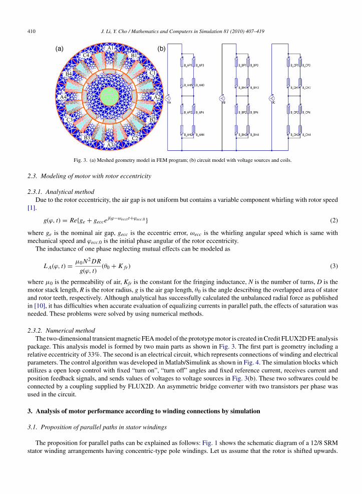
Fig. 3. (a) Meshed geometry model in FEM program; (b) circuit model with voltage sources and coils.
2.3. Modeling of motor with rotor eccentricity
2.3.1. Analytical methodDue to the rotor eccentricity, the air gap is not uniform but contains a variable component whirling with rotor speed
[1].
g(ϕ, t) = Re{ge + geccej(ϕ−ωecct t+ϕecc.0} (2)
where ge is the nominal air gap, gecc is the eccentric error, ωecc is the whirling angular speed which is same withmechanical speed and ϕecc.0 is the initial phase angular of the rotor eccentricity.
The inductance of one phase neglecting mutual effects can be modeled as
LA(ϕ, t) = μ0N2DR
g(ϕ, t)(θ0 + Kfr) (3)
where μ0 is the permeability of air, Kfr is the constant for the fringing inductance, N is the number of turns, D is themotor stack length, R is the rotor radius, g is the air gap length, θ0 is the angle describing the overlapped area of statorand rotor teeth, respectively. Although analytical has successfully calculated the unbalanced radial force as publishedin [10], it has difficulties when accurate evaluation of equalizing currents in parallel path, the effects of saturation wasneeded. These problems were solved by using numerical methods.
2.3.2. Numerical methodThe two-dimensional transient magnetic FEA model of the prototype motor is created in Credit FLUX2D FE analysis
package. This analysis model is formed by two main parts as shown in Fig. 3. The first part is geometry including arelative eccentricity of 33%. The second is an electrical circuit, which represents connections of winding and electricalparameters. The control algorithm was developed in Matlab/Simulink as shown in Fig. 4. The simulation blocks whichutilizes a open loop control with fixed “turn on”, “turn off” angles and fixed reference current, receives current andposition feedback signals, and sends values of voltages to voltage sources in Fig. 3(b). These two softwares could beconnected by a coupling supplied by FLUX2D. An asymmetric bridge converter with two transistors per phase wasused in the circuit.
3. Analysis of motor performance according to winding connections by simulation
3.1. Proposition of parallel paths in stator windings
The proposition for parallel paths can be explained as follows: Fig. 1 shows the schematic diagram of a 12/8 SRMstator winding arrangements having concentric-type pole windings. Let us assume that the rotor is shifted upwards.
J. Li, Y. Cho / Mathematics and Computers in Simulation 81 (2010) 407–419 411
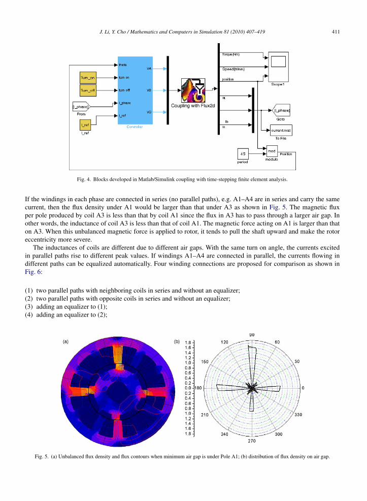
Fig. 4. Blocks developed in Matlab/Simulink coupling with time-stepping finite element analysis.
If the windings in each phase are connected in series (no parallel paths), e.g. A1–A4 are in series and carry the samecurrent, then the flux density under A1 would be larger than that under A3 as shown in Fig. 5. The magnetic fluxper pole produced by coil A3 is less than that by coil A1 since the flux in A3 has to pass through a larger air gap. Inother words, the inductance of coil A3 is less than that of coil A1. The magnetic force acting on A1 is larger than thaton A3. When this unbalanced magnetic force is applied to rotor, it tends to pull the shaft upward and make the rotoreccentricity more severe.
The inductances of coils are different due to different air gaps. With the same turn on angle, the currents excitedin parallel paths rise to different peak values. If windings A1–A4 are connected in parallel, the currents flowing indifferent paths can be equalized automatically. Four winding connections are proposed for comparison as shown inFig. 6:
(1) two parallel paths with neighboring coils in series and without an equalizer;(2) two parallel paths with opposite coils in series and without an equalizer;(3) adding an equalizer to (1);(4) adding an equalizer to (2);
Fig. 5. (a) Unbalanced flux density and flux contours when minimum air gap is under Pole A1; (b) distribution of flux density on air gap.
412 J. Li, Y. Cho / Mathematics and Computers in Simulation 81 (2010) 407–419
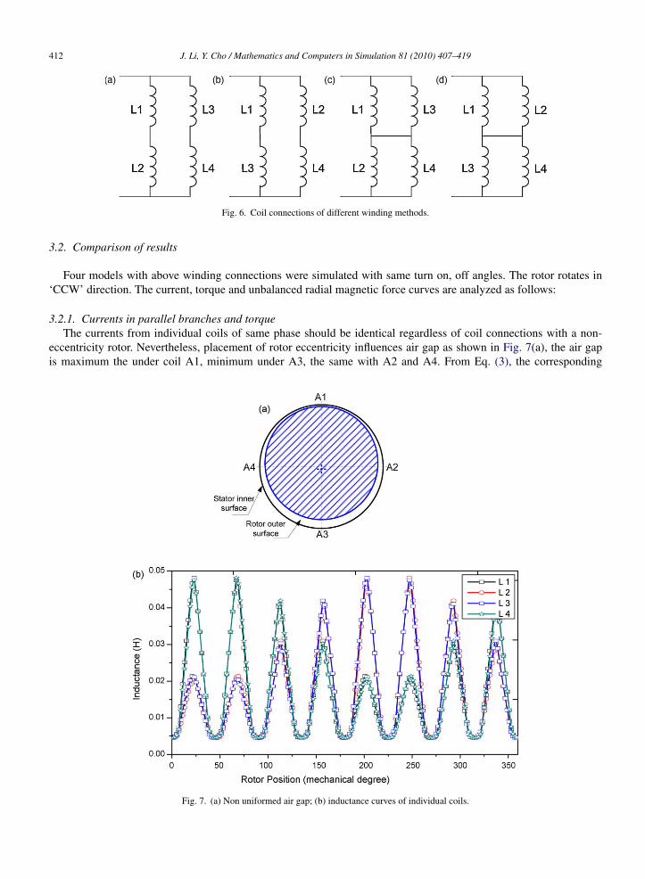
Fig. 6. Coil connections of different winding methods.
3.2. Comparison of results
Four models with above winding connections were simulated with same turn on, off angles. The rotor rotates in‘CCW’ direction. The current, torque and unbalanced radial magnetic force curves are analyzed as follows:
3.2.1. Currents in parallel branches and torqueThe currents from individual coils of same phase should be identical regardless of coil connections with a non-
eccentricity rotor. Nevertheless, placement of rotor eccentricity influences air gap as shown in Fig. 7(a), the air gapis maximum the under coil A1, minimum under A3, the same with A2 and A4. From Eq. (3), the corresponding
Fig. 7. (a) Non uniformed air gap; (b) inductance curves of individual coils.
J. Li, Y. Cho / Mathematics and Computers in Simulation 81 (2010) 407–419 413
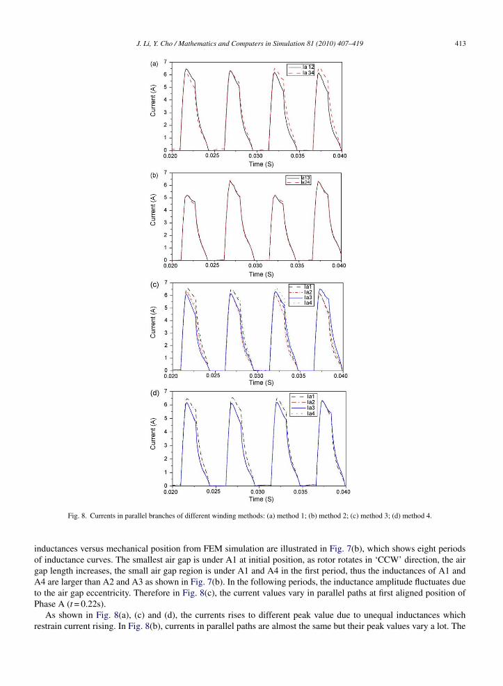
Fig. 8. Currents in parallel branches of different winding methods: (a) method 1; (b) method 2; (c) method 3; (d) method 4.
inductances versus mechanical position from FEM simulation are illustrated in Fig. 7(b), which shows eight periodsof inductance curves. The smallest air gap is under A1 at initial position, as rotor rotates in ‘CCW’ direction, the airgap length increases, the small air gap region is under A1 and A4 in the first period, thus the inductances of A1 andA4 are larger than A2 and A3 as shown in Fig. 7(b). In the following periods, the inductance amplitude fluctuates dueto the air gap eccentricity. Therefore in Fig. 8(c), the current values vary in parallel paths at first aligned position ofPhase A (t = 0.22s).
As shown in Fig. 8(a), (c) and (d), the currents rises to different peak value due to unequal inductances whichrestrain current rising. In Fig. 8(b), currents in parallel paths are almost the same but their peak values vary a lot. The
414 J. Li, Y. Cho / Mathematics and Computers in Simulation 81 (2010) 407–419
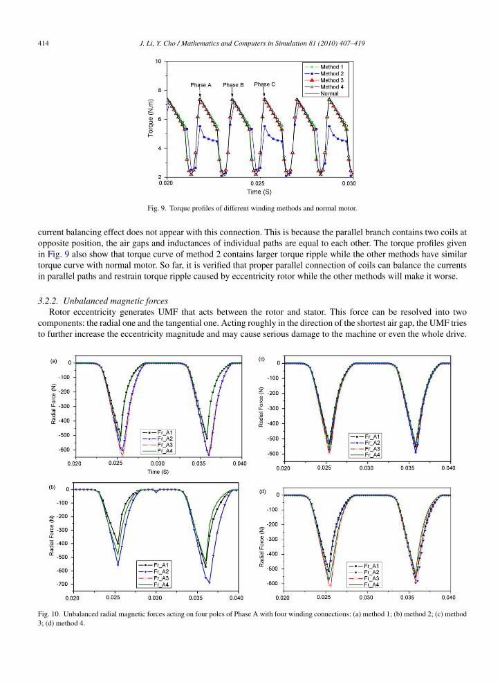
Fig. 9. Torque profiles of different winding methods and normal motor.
current balancing effect does not appear with this connection. This is because the parallel branch contains two coils atopposite position, the air gaps and inductances of individual paths are equal to each other. The torque profiles givenin Fig. 9 also show that torque curve of method 2 contains larger torque ripple while the other methods have similartorque curve with normal motor. So far, it is verified that proper parallel connection of coils can balance the currentsin parallel paths and restrain torque ripple caused by eccentricity rotor while the other methods will make it worse.
3.2.2. Unbalanced magnetic forcesRotor eccentricity generates UMF that acts between the rotor and stator. This force can be resolved into two
components: the radial one and the tangential one. Acting roughly in the direction of the shortest air gap, the UMF triesto further increase the eccentricity magnitude and may cause serious damage to the machine or even the whole drive.
Fig. 10. Unbalanced radial magnetic forces acting on four poles of Phase A with four winding connections: (a) method 1; (b) method 2; (c) method3; (d) method 4.
J. Li, Y. Cho / Mathematics and Computers in Simulation 81 (2010) 407–419 415
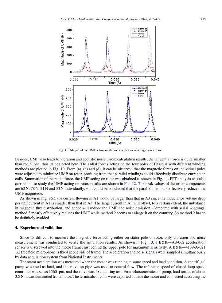
Fig. 11. Magnitude of UMF acting on the rotor with four winding connections.
Besides, UMF also leads to vibration and acoustic noise. From calculation results, the tangential force is quite smallerthan radial one, thus its neglected here. The radial forces acting on the four poles of Phase A with different windingmethods are plotted in Fig. 10. From (a), (c) and (d), it can be observed that the magnetic forces on individual poleswere adjusted to minimize UMP on rotor, profiting from that parallel windings could effectively distribute currents incoils. Summation of the radial force, the UMF acting on rotor was obtained as shown in Fig. 11. FFT analysis was alsocarried out to study the UMF acting on rotor, results are shown in Fig. 12. The peak values of 1st order componentsare 62 N, 78 N, 21 N and 53 N individually, so it could be concluded that the parallel method 3 effectively reduced theUMF magnitude.
As shown in Fig. 8(c), the current flowing in A1 would be larger than that in A3 since the inductance voltage dropper unit current in A1 is smaller than that in A3. The large current in A3 will offset, to a certain extent, the unbalancein magnetic flux distribution, and hence will reduce the UMF and noise emission. Compared with serial windings,method 3 mostly effectively reduces the UMF while method 2 seems to enlarge it on the contrary. So method 2 has tobe definitely avoided.
4. Experimental validation
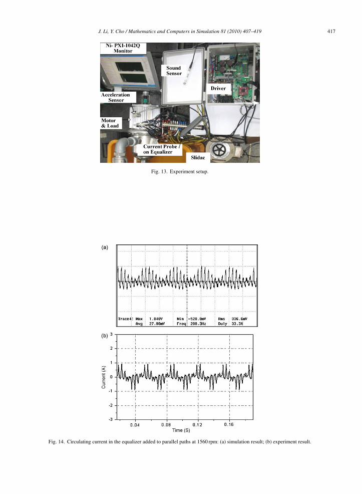
Since its difficult to measure the magnetic force acting either on stator pole or rotor, only vibration and noisemeasurement was conducted to verify the simulation results. As shown in Fig. 13, a B&K—AS-062 accelerationsensor was screwed into the motor frame, just behind the upper pole for maximum sensitivity. A B&K—4189-A-0211/2 free field microphone is fixed at one side of frame. The acceleration and noise signals were sampled simultaneouslyby data acquisition system from National Instruments.
The stator acceleration was measured when the motor was running at same speed and load condition. A centrifugalpump was used as load, and the valve on pipe was used to control flow. The reference speed of closed-loop speedcontroller was set as 1560 rpm, and the valve was fixed during test. From characteristics of pump, load torque of about3.8 N m was demanded from motor. The terminals of coils were exported outside the motor and connected according the
416 J. Li, Y. Cho / Mathematics and Computers in Simulation 81 (2010) 407–419
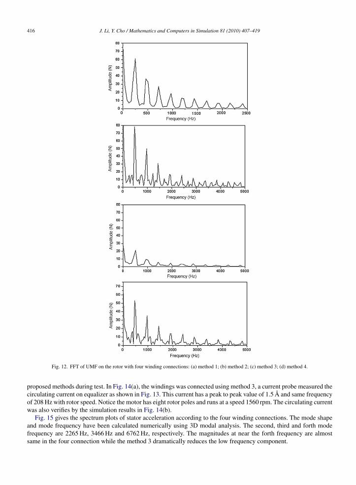
Fig. 12. FFT of UMF on the rotor with four winding connections: (a) method 1; (b) method 2; (c) method 3; (d) method 4.
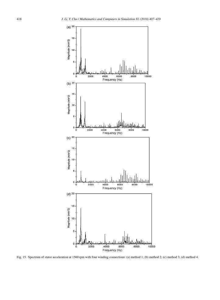
proposed methods during test. In Fig. 14(a), the windings was connected using method 3, a current probe measured thecirculating current on equalizer as shown in Fig. 13. This current has a peak to peak value of 1.5 A and same frequencyof 208 Hz with rotor speed. Notice the motor has eight rotor poles and runs at a speed 1560 rpm. The circulating currentwas also verifies by the simulation results in Fig. 14(b).
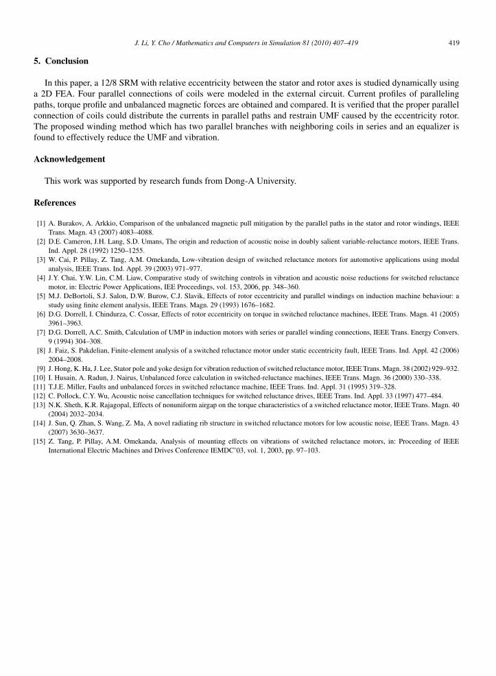
Fig. 15 gives the spectrum plots of stator acceleration according to the four winding connections. The mode shapeand mode frequency have been calculated numerically using 3D modal analysis. The second, third and forth modefrequency are 2265 Hz, 3466 Hz and 6762 Hz, respectively. The magnitudes at near the forth frequency are almostsame in the four connection while the method 3 dramatically reduces the low frequency component.
J. Li, Y. Cho / Mathematics and Computers in Simulation 81 (2010) 407–419 417
Fig. 13. Experiment setup.
Fig. 14. Circulating current in the equalizer added to parallel paths at 1560 rpm: (a) simulation result; (b) experiment result.
418 J. Li, Y. Cho / Mathematics and Computers in Simulation 81 (2010) 407–419
Fig. 15. Spectrum of stator acceleration at 1560 rpm with four winding connections: (a) method 1; (b) method 2; (c) method 3; (d) method 4.
J. Li, Y. Cho / Mathematics and Computers in Simulation 81 (2010) 407–419 419
5. Conclusion
In this paper, a 12/8 SRM with relative eccentricity between the stator and rotor axes is studied dynamically usinga 2D FEA. Four parallel connections of coils were modeled in the external circuit. Current profiles of parallelingpaths, torque profile and unbalanced magnetic forces are obtained and compared. It is verified that the proper parallelconnection of coils could distribute the currents in parallel paths and restrain UMF caused by the eccentricity rotor.The proposed winding method which has two parallel branches with neighboring coils in series and an equalizer isfound to effectively reduce the UMF and vibration.
Acknowledgement
This work was supported by research funds from Dong-A University.
References
[1] A. Burakov, A. Arkkio, Comparison of the unbalanced magnetic pull mitigation by the parallel paths in the stator and rotor windings, IEEETrans. Magn. 43 (2007) 4083–4088.
[2] D.E. Cameron, J.H. Lang, S.D. Umans, The origin and reduction of acoustic noise in doubly salient variable-reluctance motors, IEEE Trans.Ind. Appl. 28 (1992) 1250–1255.
[3] W. Cai, P. Pillay, Z. Tang, A.M. Omekanda, Low-vibration design of switched reluctance motors for automotive applications using modalanalysis, IEEE Trans. Ind. Appl. 39 (2003) 971–977.
[4] J.Y. Chai, Y.W. Lin, C.M. Liaw, Comparative study of switching controls in vibration and acoustic noise reductions for switched reluctancemotor, in: Electric Power Applications, IEE Proceedings, vol. 153, 2006, pp. 348–360.
[5] M.J. DeBortoli, S.J. Salon, D.W. Burow, C.J. Slavik, Effects of rotor eccentricity and parallel windings on induction machine behaviour: astudy using finite element analysis, IEEE Trans. Magn. 29 (1993) 1676–1682.
[6] D.G. Dorrell, I. Chindurza, C. Cossar, Effects of rotor eccentricity on torque in switched reluctance machines, IEEE Trans. Magn. 41 (2005)3961–3963.
[7] D.G. Dorrell, A.C. Smith, Calculation of UMP in induction motors with series or parallel winding connections, IEEE Trans. Energy Convers.9 (1994) 304–308.
[8] J. Faiz, S. Pakdelian, Finite-element analysis of a switched reluctance motor under static eccentricity fault, IEEE Trans. Ind. Appl. 42 (2006)2004–2008.
[9] J. Hong, K. Ha, J. Lee, Stator pole and yoke design for vibration reduction of switched reluctance motor, IEEE Trans. Magn. 38 (2002) 929–932.[10] I. Husain, A. Radun, J. Nairus, Unbalanced force calculation in switched-reluctance machines, IEEE Trans. Magn. 36 (2000) 330–338.[11] T.J.E. Miller, Faults and unbalanced forces in switched reluctance machine, IEEE Trans. Ind. Appl. 31 (1995) 319–328.[12] C. Pollock, C.Y. Wu, Acoustic noise cancellation techniques for switched reluctance drives, IEEE Trans. Ind. Appl. 33 (1997) 477–484.[13] N.K. Sheth, K.R. Rajagopal, Effects of nonuniform airgap on the torque characteristics of a switched reluctance motor, IEEE Trans. Magn. 40
(2004) 2032–2034.[14] J. Sun, Q. Zhan, S. Wang, Z. Ma, A novel radiating rib structure in switched reluctance motors for low acoustic noise, IEEE Trans. Magn. 43
(2007) 3630–3637.[15] Z. Tang, P. Pillay, A.M. Omekanda, Analysis of mounting effects on vibrations of switched reluctance motors, in: Proceeding of IEEE
International Electric Machines and Drives Conference IEMDC’03, vol. 1, 2003, pp. 97–103.


