Embed Size (px)
Citation preview
Alexandria Engineering Journal (2015) 54, 1091–1104
HO ST E D BY
Alexandria University
Alexandria Engineering Journal
www.elsevier.com/locate/aejwww.sciencedirect.com
ORIGINAL ARTICLE
Fully controlled 5-phase, 10-pulse, line commutated
rectifier
* Tel.: +968 24141314; fax: +968 24413454.
E-mail addresses: [email protected], [email protected].
Peer review under responsibility of Faculty of Engineering, Alexandria
University.
http://dx.doi.org/10.1016/j.aej.2015.07.0041110-0168 ª 2015 Faculty of Engineering, Alexandria University. Production and hosting by Elsevier B.V.This is an open access article under the CC BY-NC-ND license (http://creativecommons.org/licenses/by-nc-nd/4.0/).
Mahmoud I. Masoud *
ECE Dept., College of Engineering, Sultan Qaboos University, P.O. Box 33, Al-Khodh, P.C. 123, Muscat, Oman
Received 5 December 2014; revised 23 May 2015; accepted 4 July 2015
Available online 17 July 2015
KEYWORDS
Line commutated rectifier;
Ac–dc converter;
Multiphase machines;
Wind turbine generator;
PM generator;
Electric vehicle
Abstract The development and production of multiphase machines either generators or motors,
specially five-phase, offers improved performance compared to three-phase counterpart. Five phase
generators could generate power in applications such as, but not limited to, wind power generation,
electric vehicles, aerospace, and oil and gas. The five-phase generator output requires converter sys-
tem such as ac–dc converters. In this paper, a fully controlled 10-pulse line commutated rectifier,
suitable to be engaged with wind energy applications, fed from five-phase source is introduced.
A shunt active power filter (APF) is used to improve power factor and supply current total har-
monic distortion (THD). Compared to three-phase converters, 6-pulse or 12-pulse rectifiers, the
10-pulse rectifier engaged with 5-phase source alleviate their drawbacks such as high dc ripples
and no need for electric gear or phase shifting transformer. MATLAB/SIMULINK platform is
used as a simulation tool to investigate the performance of the proposed rectifier.ª 2015 Faculty of Engineering, Alexandria University. Production and hosting by Elsevier B.V. This is an
open access article under the CC BY-NC-ND license (http://creativecommons.org/licenses/by-nc-nd/4.0/).
1. Introduction
Nowadays, life trend has a tremendous increase of load
demand with the importance of delivering power safely andreliably. A typical power system consists of generation, trans-mission, and distribution. Many researchers work on eachstage to achieve the main required targets with optimum level
[1,2]. The generation stage has a booming state with a big con-cern of renewable energy sources such as wind power and
Photovoltaic (PV) systems or environmental friendly systemssuch as electric vehicles [2–7].
Lately, multiphase machines share the market with no
restriction of phases number. Examples for multiphase motorapplications are electric ship propulsion, aircraft drives, andlocomotive tractions [8–11]. On the other side, multiphase
generators, specially five phase [3,12–16], start to find a slotin the market, where it has the same advantages introducedwith multiphase machine drives [8,11,17–19]. It could be a
suitable candidate for direct drive wind energy, microturbines,and electric vehicle applications with no need for electricgear such as low frequency transformer or phase shiftingtransformer [20,21].
After the power generation and before transmission phase,an intermediate stage should be inserted for power processingwhich is functioned using power electronic converters. Often, it
1092 M.I. Masoud
is ac–dc converters, rectifiers which are broadly classified intotwo types. Firstly, power factor control rectifiers operate athigh switching frequency [22–24]. Many papers deal with
three-phase PWM rectifiers’ performance, simulation, model-ing, and control [22,25–29]. Secondly, line commutated recti-fiers, uncontrolled using diodes or controlled using
thyristors, operate at power frequency or generated frequency.The uncontrolled five-phase line commutated rectifiers are
introduced in Refs. [3,15,30,31]. They offer simple control, sim-
ple construction, and low cost but still have poor input powerfactor, low input current THD, and unidirectional current flow[22,32]. To alleviate such problems, PWM rectifiers, voltagesource rectifiers or current source rectifiers, are used [22,32–34].
Although, the power factor is improved, the input current tothe converter, which affects the generator or the source, shouldbe filtered. Moreover, the switch current and voltage limitation
may restrict the PWM rectifier to be used in high power scale.Accordingly, rectification can be made using thyristors,(controlled rectifier) where dc-link voltage can be controlled
by adjusting the firing angle, which offers high power capability,easy control, simple gating system, and bidirectional currentflow but it shares the uncontrolled rectifiers or PWM rectifiers
for the supply current filtering requirement.In this paper, the controlled line commutated rectifier suit-
able for wind turbine or automotive applications generatingpower via 5-phase source is introduced. Detailed analysis for
input and output performances is given and assessed. Thefive-phase PM generator has sinusoidal induced emf with theassumption of fixed wind speed. The generator performance
and effect of emf waveform harmonics, depending on PMdesign is out of scope from this manuscript as it will be inves-tigated in subsequent publications. The main target here is the
feasibility and assessment of line commutated five-phase recti-fier. A shunt APF is engaged with the system to improve thepower factor and THD due to non-linearity encountered with
the rectifier. Compared to 6-pulse rectifier (three-phase system),10-pulse rectifier fed from a source has the same amplitudeof the 6-pulse counterpart, and the average voltage has lessripples and higher average voltage for the same firing
angle. Compared to series connected 12-pulse rectifier,10-pulse rectifier has no-need for phase shifting transformerwhich attains reduction of cost due to transformer and number
of switches. Moreover, dc-link voltage value is comparable.The contribution of this paper is divided among the various
sections of this paper. Section 2 details the controlled 5-phase
rectifier and how the output voltage is generated. Section 3details the analysis and performance for both dc-side and ac-side. Section 4 shows how the firing angle is generated andhow to improve the ac-side power factor and THD using shunt
APF through a system consists mainly of 10-pulse rectifier fedfrom 5-phase PM generator operated at fixed speed with shuntAPF coupled to the point of common coupling (PCC).
Simulation results for different firing angles are introduced inSection 5; moreover, discussion and comparison with 6-pulseand 12-pulse converter are given. Finally, the manuscript is
concluded.
2. Five-phase controlled rectifier
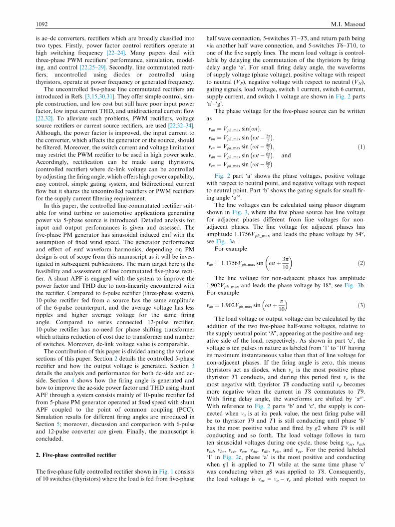
The five-phase fully controlled rectifier shown in Fig. 1 consistsof 10 switches (thyristors) where the load is fed from five-phase
half wave connection, 5-switches T1–T5, and return path beingvia another half wave connection, and 5-switches T6–T10, toone of the five supply lines. The mean load voltage is control-
lable by delaying the commutation of the thyristors by firingdelay angle ‘a’. For small firing delay angle, the waveformsof supply voltage (phase voltage), positive voltage with respect
to neutral (VP), negative voltage with respect to neutral (VN),gating signals, load voltage, switch 1 current, switch 6 current,supply current, and switch 1 voltage are shown in Fig. 2 parts
‘a’–‘g’.The phase voltage for the five-phase source can be written
as
van ¼ Vph max sinðxtÞ;vbn ¼ Vph max sin xt� 2p
5
� �;
vcn ¼ Vph max sin xt� 4p5
� �;
vdn ¼ Vph max sin xt� 6p5
� �; and
ven ¼ Vph max sin xt� 8p5
� �ð1Þ
Fig. 2 part ‘a’ shows the phase voltages, positive voltagewith respect to neutral point, and negative voltage with respect
to neutral point. Part ‘b’ shows the gating signals for small fir-ing angle ‘a�’.
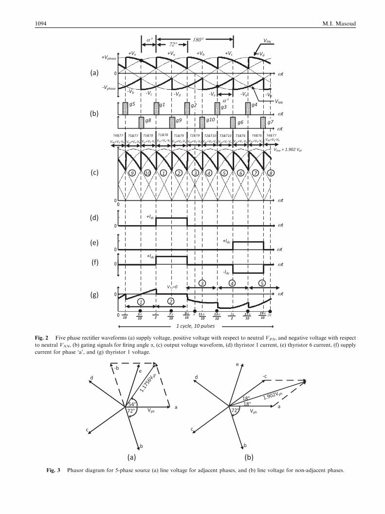
The line voltages can be calculated using phasor diagramshown in Fig. 3, where the five phase source has line voltage
for adjacent phases different from line voltages for non-adjacent phases. The line voltage for adjacent phases hasamplitude 1.1756Vph_max and leads the phase voltage by 54�,see Fig. 3a.
For example
vab ¼ 1:1756Vph max sin xtþ 3p10
� �ð2Þ
The line voltage for non-adjacent phases has amplitude1.902Vph_max and leads the phase voltage by 18�, see Fig. 3b.For example
vab ¼ 1:902Vph max sin xtþ p10
� �ð3Þ
The load voltage or output voltage can be calculated by theaddition of the two five-phase half-wave voltages, relative to
the supply neutral point ‘N’, appearing at the positive and neg-ative side of the load, respectively. As shown in part ‘c’, thevoltage is ten pulses in nature as labeled from ‘1’ to ‘10’ havingits maximum instantaneous value than that of line voltage for
non-adjacent phases. If the firing angle is zero, this meansthyristors act as diodes, when va is the most positive phasethyristor T1 conducts, and during this period first vc is the
most negative with thyristor T8 conducting until vd becomesmore negative when the current in T8 commutates to T9.With firing delay angle, the waveforms are shifted by ‘a�’.With reference to Fig. 2 parts ‘b’ and ‘c’, the supply is con-nected when va is at its peak value, the next firing pulse willbe to thyristor T9 and T1 is still conducting until phase ‘b’
has the most positive value and fired by g2 where T9 is stillconducting and so forth. The load voltage follows in turnten sinusoidal voltages during one cycle, those being vac, vad,vbd, vbe, vce, vca, vda, vdb, veb, and vec. For the period labeled
‘1’ in Fig. 2c, phase ‘a’ is the most positive and conductingwhen g1 is applied to T1 while at the same time phase ‘c’was conducting when g8 was applied to T8. Consequently,
the load voltage is vac = va � vc and plotted with respect to
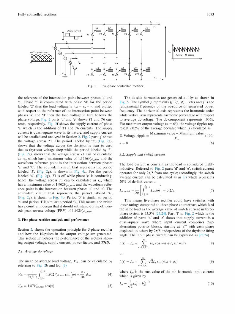
Fig. 1 Five-phase controlled rectifier.
Fully controlled rectifiers 1093
the reference of the intersection point between phases ‘a’ and
‘c’. Phase ‘c’ is commutated with phase ‘d’ for the periodlabeled ‘2’ thus the load voltage is vad = va � vd and plottedwith respect to the reference of the intersection point betweenphases ‘a’ and ‘d’ then the load voltage in turn follows the
phase voltage. Fig. 2 parts ‘d’ and ‘e’ shows T1 and T6 cur-rents, respectively. Fig. 2f shows the supply current of phase‘a’ which is the addition of T1 and T6 currents. The supply
current is quasi-square wave in its nature, and supply currentwill be detailed and analyzed in Section 2. Fig. 2 part ‘g’ showsthe voltage across T1. The period labeled by ‘2’, (Fig. 2g),
shows that the voltage across the thyristor is near to zerodue to thyristor voltage drop while the period labeled by ‘3’,(Fig. 2g), shows that the voltage across T1 can be calculated
as vba which has a maximum value of 1.1756Vph_max and thewaveform reference point is the intersection between phases‘a’ and ‘b’. The equivalent circuit that represents the periodlabeled ‘3’, (Fig. 2g), is shown in Fig. 4a. For the period
labeled ‘4’, (Fig. 2g), T1 is off while phase ‘c’ is conducting;hence, the voltage across T1 can be calculated as vca whichhas a maximum value of 1.902Vph_max and the waveform refer-
ence point is the intersection between phases ‘a’ and ‘c’. Theequivalent circuit that represents the period labeled ‘4’,(Fig. 2g), is shown in Fig. 4b. Period ‘5’ is similar to period
‘4’ and period ‘1’ is similar to period ‘3’. This means, the switchhas a constraint design that it should withstand during off peri-ods peak reverse voltage (PRV) of 1.902Vph_max.
3. Five-phase rectifier analysis and performance
Section 2, shows the operation principle for 5-phase rectifier
and how the 10-pulses in the output voltage are generated.This section introduces the performance of the rectifier show-ing output voltage, supply current, power factor, and THD.
3.1. Average dc-voltage
The mean or average load voltage, Vdc, can be calculated byreferring to Fig. 2b and Eq. (3)
Vdc ¼1
2p=10
Z p2þa
3p10þa
1:902Vph max sin xtþ p10
� �dxt ð4Þ
Vdc ¼ 1:87Vph max cosðaÞ ð5Þ
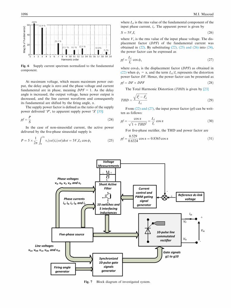
The dc-side harmonics are generated at 10p as shown in
Fig. 5. The symbol p represents (f, 2f, 3f, . . .etc) and f is thefundamental frequency of the ac-source or generated powerfrequency. The horizontal axis represents the harmonic orderwhile vertical axis represents harmonic percentage with respect
to average dc-voltage. The dc-component represents 100%.For maximum output voltage (a = 0�), the voltage ripples rep-resent 2.02% of the average dc-value which is calculated as
% Voltage ripple ¼Maximum value�Minimum value
Vdc
� 100;
a ¼ 0 ð6Þ
3.2. Supply and switch current
The load current is constant as the load is considered highlyinductive. Referred to Fig. 2 parts ‘d’ and ‘e’, switch current
operates for only 2p/5 from one cycle; accordingly, the switchaverage current can be calculated as in (7) which represents20% of dc-link current.
Iav switch ¼1
2p
Z 7p10þa
3p10þa
Idcdxt
" #¼ 0:2Idc ð7Þ
This means five-phase rectifier could have switches with
lower ratings compared to three-phase counterpart which feedthe same load as the average value of switch current in three-phase system is 33.3% [23,24]. Part ‘f’ in Fig. 2 which is the
addition of parts ‘d’ and ‘e’ shows that supply current is aquasi-square wave where input current comprises 2p/5alternating polarity blocks, starting at ‘a�’ with each phase
displaced to others by 2p/5, independent of the thyristor firingangle. The input phase current can be expressed as [23,24]
isðtÞ ¼ Iav þX1
n¼1;3;5;7;...ðan cos nxtþ bn sin nxtÞ ð8Þ
or
isðtÞ ¼ Iav þX1
n¼1;2;3;...
ffiffiffi2p
Isn sinðnxtþ /nÞ ð9Þ
where Isn is the rms value of the nth harmonic input currentwhich is given by
Isn ¼1ffiffiffi2p ða2n þ b2nÞ
1=2 ð10Þ
(a)
(b)
(c)
(d)
(e)
(f)
(g)
Fig. 2 Five phase rectifier waveforms (a) supply voltage, positive voltage with respect to neutral VPN, and negative voltage with respect
to neutral VNN, (b) gating signals for firing angle a, (c) output voltage waveform, (d) thyristor 1 current, (e) thyristor 6 current, (f) supply
current for phase ‘a’, and (g) thyristor 1 voltage.
Fig. 3 Phasor diagram for 5-phase source (a) line voltage for adjacent phases, and (b) line voltage for non-adjacent phases.
1094 M.I. Masoud
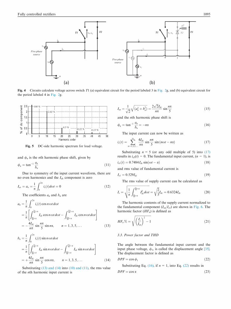
Fig. 4 Circuits calculate voltage across switch T1 (a) equivalent circuit for the period labeled 3 in Fig. 2g, and (b) equivalent circuit for
the period labeled 4 in Fig. 2g.
2.02 %
0.5 % 0.22 % 0.13 %
100 %
Fig. 5 DC-side harmonic spectrum for load voltage.
Fully controlled rectifiers 1095
and /n is the nth harmonic phase shift, given by
/n ¼ tan�1anbn
ð11Þ
Due to symmetry of the input current waveform, there areno even harmonics and the Idc component is zero
Iav ¼ ao ¼1
p
Z 2p
0
isðtÞdxt ¼ 0 ð12Þ
The coefficients an and bn are
an ¼1
p
Z 2p
0
isðtÞ cos nxtdxt
¼ 1
p
Z 7p10þa
3p10þa
Idc cos nxtdxt�Z 17p
10þa
13p10þa
Idc cos nxtdxt
" #
¼ � 4Idcnp
sinnp5
sin na; n ¼ 1; 3; 5; . . . ð13Þ
bn ¼1
p
Z 2p
0
isðtÞ sin nxtdxt
¼ 1
p
Z 7p10þa
3p10þa
Idc sin nxtdxt�Z 17p
10þa
13p10þa
Idc sin nxtdxt
" #
¼ þ 4Idcnp
sinnp5
cos na; n ¼ 1; 3; 5; . . . ð14Þ
Substituting (13) and (14) into (10) and (11), the rms valueof the nth harmonic input current is
Isn ¼1ffiffiffi2p
ffiffiffiffiffiffiffiffiffiffiffiffiffiffiffiffiffiffiða2n þ b2nÞ
q¼ 2
ffiffiffi2p
Idcnp
sinnp5
ð15Þ
and the nth harmonic phase shift is
/n ¼ tan�1anbn¼ �na ð16Þ
The input current can now be written as
isðtÞ ¼X1
n¼1;3;5;...
4Idcnp
sinnp5
sin ðnxt� naÞ ð17Þ
Substituting n= 5 (or any odd multiple of 5) into (17)results in is5(t) = 0. The fundamental input current, (n= 1), is
is1ðtÞ ¼ 0:7484 Idc sinðxt� aÞ ð18Þ
and rms value of fundamental current is
Is1 ¼ 0:529Idc ð19Þ
The rms value of supply current can be calculated as
Is ¼
ffiffiffiffiffiffiffiffiffiffiffiffiffiffiffiffiffiffiffiffiffiffiffiffiffiffiffiffiffiffi1
p
Z 7p10þa
3p10þa
I2dcdxt
vuut ¼ffiffiffi2
5
rIdc ¼ 0:6324Idc ð20Þ
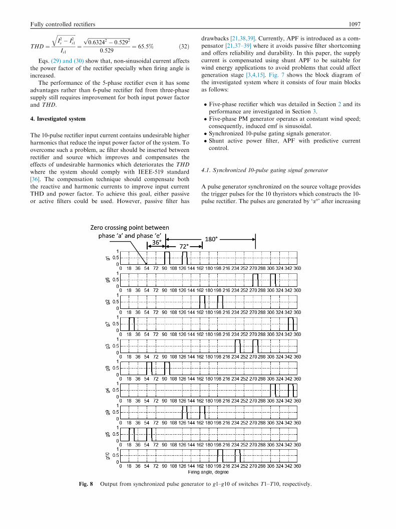
The harmonic contents of the supply current normalized tothe fundamental component (Isn/Is1) are shown in Fig. 6. Theharmonic factor (HFn) is defined as
HFn % ¼
ffiffiffiffiffiffiffiffiffiffiffiffiffiffiffiffiffiffiffiffiffiffiIsIsn
� �2
� 1
sð21Þ
3.3. Power factor and THD
The angle between the fundamental input current and the
input phase voltage, /1, is called the displacement angle [35].The displacement factor is defined as
DPF ¼ cos/1 ð22Þ
Substituting Eq. (16), if n = 1, into Eq. (22) results in
DPF ¼ cos a ð23Þ
53.9 %
23.1 %
100%
9.1 % 12.5 % 11.1 % 9.52% 5.3%
Fig. 6 Supply current spectrum normalized to the fundamental
component.
1096 M.I. Masoud
At maximum voltage, which means maximum power out-
put, the delay angle is zero and the phase voltage and currentfundamental are in phase, meaning DPF = 1. As the delayangle is increased, the output voltage, hence power output is
decreased, and the line current waveform and consequentlyits fundamental are shifted by the firing angle, a.
The supply power factor is defined as the ratio of the supply
power delivered ‘P’, to apparent supply power ‘S’ [35]:
pf ¼ P
Sð24Þ
In the case of non-sinusoidal current, the active powerdelivered by the five-phase sinusoidal supply is
P ¼ 5� 1
2p
Z 2p
0
vsðxtÞisðxtÞdxt ¼ 5VsIs1 cos/1 ð25Þ
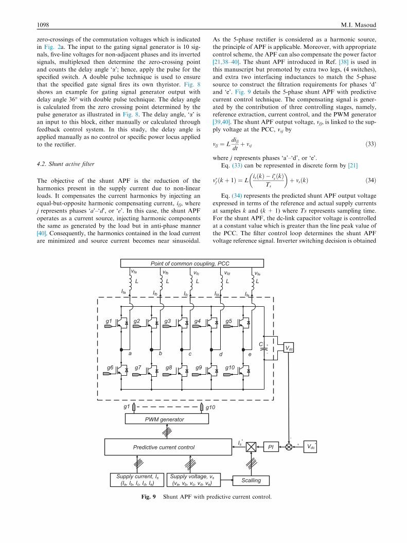
Fig. 7 Block diagram o
where Is1 is the rms value of the fundamental component of the
input phase current, is. The apparent power is given by
S ¼ 5VsIs ð26Þ
where Vs is the rms value of the input phase voltage. The dis-placement factor (DPF) of the fundamental current was
obtained in (22). By substituting (22), (25) and (26) into (24),the power factor can be expressed as
pf ¼ Is1Is
cos/1 ð27Þ
where cos/1 is the displacement factor (DPF) as obtained in(22) when /1 = a, and the term Is1/Is represents the distortion
power factor DF. Hence, the power factor can be presented as
pf ¼ DF�DPF ð28Þ
The Total Harmonic Distortion (THD) is given by [23]
THD ¼
ffiffiffiffiffiffiffiffiffiffiffiffiffiffiffiI2s � I2s1
qIs1
ð29Þ
From (22) and (27), the input power factor (pf) can be writ-ten as follows:
pf ¼ cos affiffiffiffiffiffiffiffiffiffiffiffiffiffiffiffiffiffiffiffiffi1þ THD2
p ¼ Is1Is
cos a ð30Þ
For five-phase rectifier, the THD and power factor are
pf ¼ 0:529
0:6324cos a ¼ 0:8365 cos a ð31Þ
f investigated system.
Fully controlled rectifiers 1097
THD ¼
ffiffiffiffiffiffiffiffiffiffiffiffiffiffiffiI2s � I2s1
qIs1
¼ffiffiffiffiffiffiffiffiffiffiffiffiffiffiffiffiffiffiffiffiffiffiffiffiffiffiffiffiffiffiffiffiffiffi0:63242 � 0:5292p
0:529¼ 65:5% ð32Þ
Eqs. (29) and (30) show that, non-sinusoidal current affects
the power factor of the rectifier specially when firing angle isincreased.
The performance of the 5-phase rectifier even it has someadvantages rather than 6-pulse rectifier fed from three-phase
supply still requires improvement for both input power factorand THD.
4. Investigated system
The 10-pulse rectifier input current contains undesirable higher
harmonics that reduce the input power factor of the system. Toovercome such a problem, ac filter should be inserted betweenrectifier and source which improves and compensates the
effects of undesirable harmonics which deteriorates the THDwhere the system should comply with IEEE-519 standard[36]. The compensation technique should compensate both
the reactive and harmonic currents to improve input currentTHD and power factor. To achieve this goal, either passiveor active filters could be used. However, passive filter has
Fig. 8 Output from synchronized pulse generato
drawbacks [21,38,39]. Currently, APF is introduced as a com-pensator [21,37–39] where it avoids passive filter shortcomingand offers reliability and durability. In this paper, the supply
current is compensated using shunt APF to be suitable forwind energy applications to avoid problems that could affectgeneration stage [3,4,15]. Fig. 7 shows the block diagram of
the investigated system where it consists of four main blocksas follows:
� Five-phase rectifier which was detailed in Section 2 and itsperformance are investigated in Section 3.� Five-phase PM generator operates at constant wind speed;consequently, induced emf is sinusoidal.
� Synchronized 10-pulse gating signals generator.� Shunt active power filter, APF with predictive currentcontrol.
4.1. Synchronized 10-pulse gating signal generator
A pulse generator synchronized on the source voltage providesthe trigger pulses for the 10 thyristors which constructs the 10-pulse rectifier. The pulses are generated by ‘a�’ after increasing
r to g1–g10 of switches T1–T10, respectively.
1098 M.I. Masoud
zero-crossings of the commutation voltages which is indicatedin Fig. 2a. The input to the gating signal generator is 10 sig-nals, five-line voltages for non-adjacent phases and its inverted
signals, multiplexed then determine the zero-crossing pointand counts the delay angle ‘a’; hence, apply the pulse for thespecified switch. A double pulse technique is used to ensure
that the specified gate signal fires its own thyristor. Fig. 8shows an example for gating signal generator output withdelay angle 36� with double pulse technique. The delay angle
is calculated from the zero crossing point determined by thepulse generator as illustrated in Fig. 8. The delay angle, ‘a’ isan input to this block, either manually or calculated throughfeedback control system. In this study, the delay angle is
applied manually as no control or specific power locus appliedto the rectifier.
4.2. Shunt active filter
The objective of the shunt APF is the reduction of theharmonics present in the supply current due to non-linear
loads. It compensates the current harmonics by injecting anequal-but-opposite harmonic compensating current, ifj, wherej represents phases ‘a’–‘d’, or ‘e’. In this case, the shunt APF
operates as a current source, injecting harmonic componentsthe same as generated by the load but in anti-phase manner[40]. Consequently, the harmonics contained in the load currentare minimized and source current becomes near sinusoidal.
Fig. 9 Shunt APF with pr
As the 5-phase rectifier is considered as a harmonic source,the principle of APF is applicable. Moreover, with appropriatecontrol scheme, the APF can also compensate the power factor
[21,38–40]. The shunt APF introduced in Ref. [38] is used inthis manuscript but promoted by extra two legs, (4 switches),and extra two interfacing inductances to match the 5-phase
source to construct the filtration requirements for phases ‘d’and ‘e’. Fig. 9 details the 5-phase shunt APF with predictivecurrent control technique. The compensating signal is gener-
ated by the contribution of three controlling stages, namely,reference extraction, current control, and the PWM generator[39,40]. The shunt APF output voltage, vfj, is linked to the sup-ply voltage at the PCC, vsj by
vfj ¼ Ldifjdtþ vsj ð33Þ
where j represents phases ‘a’–‘d’, or ‘e’.
Eq. (33) can be represented in discrete form by [21]
v�f ðkþ 1Þ ¼ LisðkÞ � i�s ðkÞ
Ts
� �þ vsðkÞ ð34Þ
Eq. (34) represents the predicted shunt APF output voltage
expressed in terms of the reference and actual supply currentsat samples k and (k + 1) where Ts represents sampling time.For the shunt APF, the dc-link capacitor voltage is controlled
at a constant value which is greater than the line peak value ofthe PCC. The filter control loop determines the shunt APFvoltage reference signal. Inverter switching decision is obtained
edictive current control.
(a)
(g)
(d)
(c)
(b)
(e)
(f)
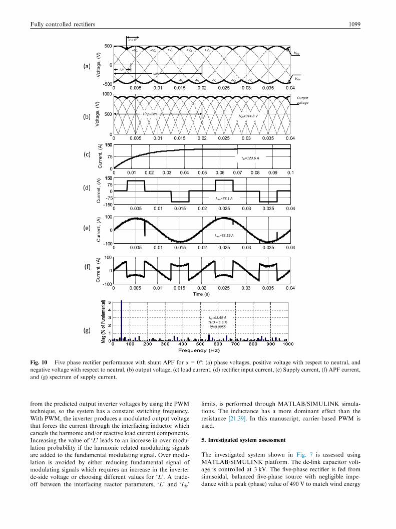
Fig. 10 Five phase rectifier performance with shunt APF for a = 0�: (a) phase voltages, positive voltage with respect to neutral, and
negative voltage with respect to neutral, (b) output voltage, (c) load current, (d) rectifier input current, (e) Supply current, (f) APF current,
and (g) spectrum of supply current.
Fully controlled rectifiers 1099
from the predicted output inverter voltages by using the PWMtechnique, so the system has a constant switching frequency.
With PWM, the inverter produces a modulated output voltagethat forces the current through the interfacing inductor whichcancels the harmonic and/or reactive load current components.
Increasing the value of ‘L’ leads to an increase in over modu-lation probability if the harmonic related modulating signalsare added to the fundamental modulating signal. Over modu-
lation is avoided by either reducing fundamental signal ofmodulating signals which requires an increase in the inverterdc-side voltage or choosing different values for ‘L’. A trade-off between the interfacing reactor parameters, ‘L’ and ‘Idc’
limits, is performed through MATLAB/SIMULINK simula-tions. The inductance has a more dominant effect than the
resistance [21,39]. In this manuscript, carrier-based PWM isused.
5. Investigated system assessment
The investigated system shown in Fig. 7 is assessed usingMATLAB/SIMULINK platform. The dc-link capacitor volt-
age is controlled at 3 kV. The five-phase rectifier is fed fromsinusoidal, balanced five-phase source with negligible impe-dance with a peak (phase) value of 490 V to match wind energy
(a)
(g)
(d)
(c)
(b)
(e)
(f)
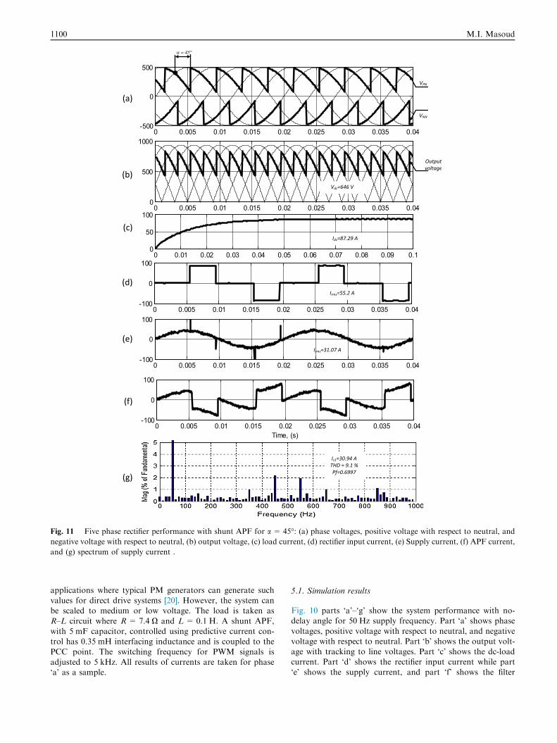
Fig. 11 Five phase rectifier performance with shunt APF for a = 45�: (a) phase voltages, positive voltage with respect to neutral, and
negative voltage with respect to neutral, (b) output voltage, (c) load current, (d) rectifier input current, (e) Supply current, (f) APF current,
and (g) spectrum of supply current .
1100 M.I. Masoud
applications where typical PM generators can generate suchvalues for direct drive systems [20]. However, the system canbe scaled to medium or low voltage. The load is taken as
R–L circuit where R= 7.4 X and L = 0.1 H. A shunt APF,with 5 mF capacitor, controlled using predictive current con-trol has 0.35 mH interfacing inductance and is coupled to thePCC point. The switching frequency for PWM signals is
adjusted to 5 kHz. All results of currents are taken for phase‘a’ as a sample.
5.1. Simulation results
Fig. 10 parts ‘a’–‘g’ show the system performance with no-delay angle for 50 Hz supply frequency. Part ‘a’ shows phase
voltages, positive voltage with respect to neutral, and negativevoltage with respect to neutral. Part ‘b’ shows the output volt-age with tracking to line voltages. Part ‘c’ shows the dc-loadcurrent. Part ‘d’ shows the rectifier input current while part
‘e’ shows the supply current, and part ‘f’ shows the filter
(a)
(g)
(d)
(c)
(b)
(e)
(f)
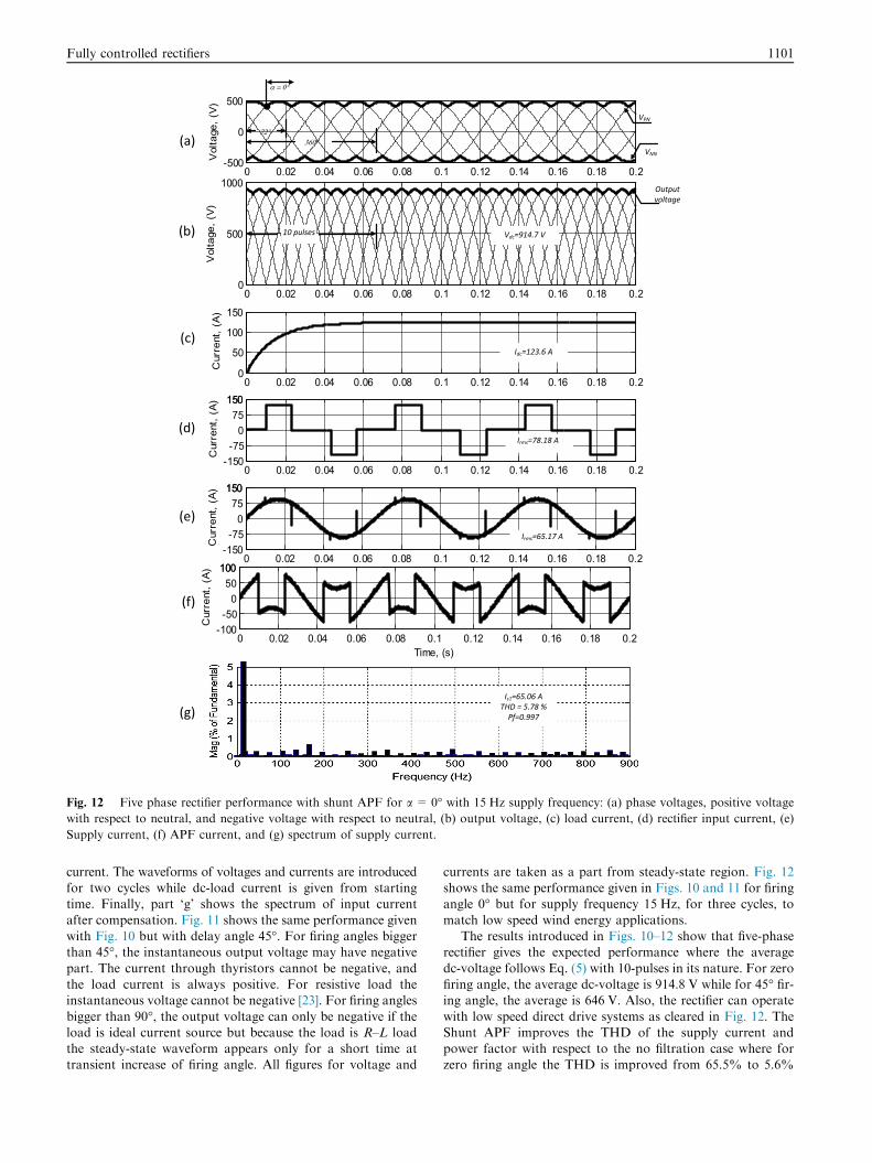
Fig. 12 Five phase rectifier performance with shunt APF for a = 0� with 15 Hz supply frequency: (a) phase voltages, positive voltage
with respect to neutral, and negative voltage with respect to neutral, (b) output voltage, (c) load current, (d) rectifier input current, (e)
Supply current, (f) APF current, and (g) spectrum of supply current.
Fully controlled rectifiers 1101
current. The waveforms of voltages and currents are introducedfor two cycles while dc-load current is given from startingtime. Finally, part ‘g’ shows the spectrum of input current
after compensation. Fig. 11 shows the same performance givenwith Fig. 10 but with delay angle 45�. For firing angles biggerthan 45�, the instantaneous output voltage may have negative
part. The current through thyristors cannot be negative, andthe load current is always positive. For resistive load theinstantaneous voltage cannot be negative [23]. For firing angles
bigger than 90�, the output voltage can only be negative if theload is ideal current source but because the load is R–L loadthe steady-state waveform appears only for a short time attransient increase of firing angle. All figures for voltage and
currents are taken as a part from steady-state region. Fig. 12shows the same performance given in Figs. 10 and 11 for firingangle 0� but for supply frequency 15 Hz, for three cycles, to
match low speed wind energy applications.The results introduced in Figs. 10–12 show that five-phase
rectifier gives the expected performance where the average
dc-voltage follows Eq. (5) with 10-pulses in its nature. For zerofiring angle, the average dc-voltage is 914.8 V while for 45� fir-ing angle, the average is 646 V. Also, the rectifier can operate
with low speed direct drive systems as cleared in Fig. 12. TheShunt APF improves the THD of the supply current andpower factor with respect to the no filtration case where forzero firing angle the THD is improved from 65.5% to 5.6%
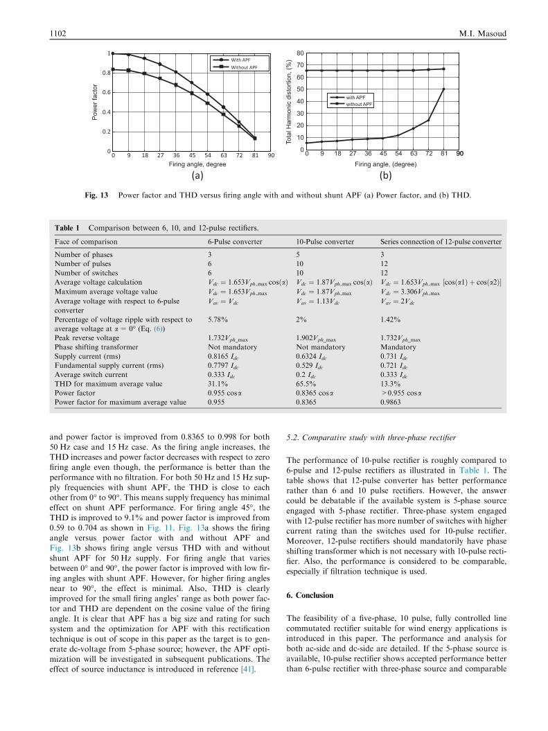
(a) (b)
0 9 18 27 36 45 54 63 72 81 900
0.2
0.4
0.6
0.8
1
Firing angle, degree
Pow
er fa
ctor
With APFWithout APF
0 9 18 27 36 45 54 63 72 81 90900
10
20
30
40
50
60
70
80
Firing angle, (degree)
Tota
l Har
mon
ic d
isto
rtion
, (%
)
with APFwithout APF
Fig. 13 Power factor and THD versus firing angle with and without shunt APF (a) Power factor, and (b) THD.
Table 1 Comparison between 6, 10, and 12-pulse rectifiers.
Face of comparison 6-Pulse converter 10-Pulse converter Series connection of 12-pulse converter
Number of phases 3 5 3
Number of pulses 6 10 12
Number of switches 6 10 12
Average voltage calculation Vdc ¼ 1:653Vph max cosðaÞ Vdc ¼ 1:87Vph max cosðaÞ Vdc ¼ 1:653Vph max ½cosða1Þ þ cosða2Þ�Maximum average voltage value Vdc ¼ 1:653Vph max Vdc ¼ 1:87Vph max Vdc ¼ 3:306Vph max
Average voltage with respect to 6-pulse
converter
Vav ¼ Vdc Vav ¼ 1:13Vdc Vav ¼ 2Vdc
Percentage of voltage ripple with respect to
average voltage at a = 0� (Eq. (6))
5.78% 2% 1.42%
Peak reverse voltage 1.732Vph_max 1.902Vph_max 1.732Vph_max
Phase shifting transformer Not mandatory Not mandatory Mandatory
Supply current (rms) 0.8165 Idc 0.6324 Idc 0.731 IdcFundamental supply current (rms) 0.7797 Idc 0.529 Idc 0.721 IdcAverage switch current 0.333 Idc 0.2 Idc 0.333 IdcTHD for maximum average value 31.1% 65.5% 13.3%
Power factor 0.955 cosa 0.8365 cosa >0.955 cosaPower factor for maximum average value 0.955 0.8365 0.9863
1102 M.I. Masoud
and power factor is improved from 0.8365 to 0.998 for both
50 Hz case and 15 Hz case. As the firing angle increases, theTHD increases and power factor decreases with respect to zerofiring angle even though, the performance is better than the
performance with no filtration. For both 50 Hz and 15 Hz sup-ply frequencies with shunt APF, the THD is close to eachother from 0� to 90�. This means supply frequency has minimal
effect on shunt APF performance. For firing angle 45�, theTHD is improved to 9.1% and power factor is improved from0.59 to 0.704 as shown in Fig. 11. Fig. 13a shows the firingangle versus power factor with and without APF and
Fig. 13b shows firing angle versus THD with and withoutshunt APF for 50 Hz supply. For firing angle that variesbetween 0� and 90�, the power factor is improved with low fir-
ing angles with shunt APF. However, for higher firing anglesnear to 90�, the effect is minimal. Also, THD is clearlyimproved for the small firing angles’ range as both power fac-
tor and THD are dependent on the cosine value of the firingangle. It is clear that APF has a big size and rating for suchsystem and the optimization for APF with this rectification
technique is out of scope in this paper as the target is to gen-erate dc-voltage from 5-phase source; however, the APF opti-mization will be investigated in subsequent publications. Theeffect of source inductance is introduced in reference [41].
5.2. Comparative study with three-phase rectifier
The performance of 10-pulse rectifier is roughly compared to
6-pulse and 12-pulse rectifiers as illustrated in Table 1. Thetable shows that 12-pulse converter has better performancerather than 6 and 10 pulse rectifiers. However, the answercould be debatable if the available system is 5-phase source
engaged with 5-phase rectifier. Three-phase system engagedwith 12-pulse rectifier has more number of switches with highercurrent rating than the switches used for 10-pulse rectifier.
Moreover, 12-pulse rectifiers should mandatorily have phaseshifting transformer which is not necessary with 10-pulse recti-fier. Also, the performance is considered to be comparable,
especially if filtration technique is used.
6. Conclusion
The feasibility of a five-phase, 10 pulse, fully controlled linecommutated rectifier suitable for wind energy applications isintroduced in this paper. The performance and analysis for
both ac-side and dc-side are detailed. If the 5-phase source isavailable, 10-pulse rectifier shows accepted performance betterthan 6-pulse rectifier with three-phase source and comparable
Fully controlled rectifiers 1103
with 12-pulse rectifier. The switch in 10-pulse rectifier haslower ratings as it carries only 20% of load current duringone cycle while it carries 33.3% for either 6-pulse or 12-pulse
counterpart. Moreover, 5-phase, 10-pulse line commutatedrectifier has no need for phase shifting transformer such as12-pulse converter which is considered as a big saving and
could be optimum for 5-phase direct drive wind turbine appli-cations. Like any rectifier, 10-pulse rectifier as a non-linearload causes undesirable harmonics in the input current that
reduces the input power factor and THD of the system. Theproblem can be overcome using ac filter. In this paper, 5-phase shunt APF was used where the input current THDand power factor are improved. The supply frequency has no
big much effect on APF performance as the study shows butstill the APF needs optimization. The APF optimization andPM generator performance are out of scope from this work
and will come in subsequent publications. The trade-offbetween 5-phase PWM rectifier and controlled line commu-tated rectifier is still debatable until a complete comparative
study is made between them.
Acknowledgment
The author likes to thank Sultan Qaboos University – Muscat– Oman as this work will be funded by internal Grant with
code number (IG/ENG/ECED/15/03).
References
[1] B. Wu, High Power Converters and AC Drives, IEEE Press,
Piscataway, NJ, 2006.
[2] M.A. El-sharkawi, Electric Energy: An introduction, CRC
Press, 2005.
[3] N.E. Hassanain, J.E. Fletcher, Steady-state performance
assessment of three- and five-phase permanent magnet
generators connected to a diode bridge rectifier under open-
circuit faults, IET Renew. Power Gener. 4 (5) (2010) 420–427.
[4] L. Li, E. Semail, L. Kobvlanski, X. Kestelyn, Flux-weakening
strategies for a five-phase PM synchronous machine, in:
Proceedings of the 14th European Conference on Power
Electronics and Applications EPE, 2011.
[5] R. Nilsen, I. Sorfonn, Hybrid power generation systems, in: 13th
European Conference on Power Electronics and Applications.
EPE’09, 2009.
[6] P. Rodriguez, I. Canadela, A. Luna, Control of PV generation
systems using the synchronous power controller, IEEE Energy
Conversion Congress and Exposition (ECCE), 2013.
[7] J.T. Bialasiewicz, Renewable energy systems with photovoltaic
power generators: operation and modeling, IEEE Trans. Ind.
Electron. 55 (7) (2008) 2752–2758.
[8] E. Levi, Multiphase electric machines for variable-speed
applications, IEEE Trans. Ind. Electron. 55 (5) (2008) 1893–
1909.
[9] G.K. Singh, Multi-phase induction machine drive research––a
survey, Electr. Power Syst. Res. 61 (2) (2002) 139–147.
[10] A.S. Abdel-Khalik, M.I. Masoud, B.W. Williams, Eleven phase
induction machine: steady-state analysis and performance
evaluation with harmonic injection, Inst. Eng. Technol. IET
Electr. Power Appl. EPA 4 (8) (2010) 670–685.
[11] A.S. Abdel-Khalik, M.I. Masoud, B.W. Williams, Vector
controlled multiphase induction machine: Harmonic injection
using optimized constant gains, Electr. Power Syst. Res. 89
(2012) 116–128.
[12] Z. Deming, O. Xin, Z. Nan, Y. Yangguang, A novel five phase
fault tolerant doubly salient electromagnetic generator for direct
driven wind turbine, Int. Conf. Electr. Mach. Syst. (ICEMS)
(2008) 2418–2422.
[13] M. Mihai, S. Benelghali, L. Livadaru, A. Simion, R. Outbib,
FEM analysis upon significance of different permanent magnet
types used in a five-phase PM generator for gearless small-scale
wind, XXth International Conference on Electrical Machines
ICEM, 2012.
[14] M.T. Mohamed, J.E. Fletcher, Five-phase permanent magnet
machines, advantages and applications, in: 5th IET
International Conference on Power Electronics, Machines and
Drives PEMD, 2010.
[15] K. Sosthenes, B. Adeola, O. Olorunfemi, A five-phase interior
Permanent magnet generator-diode rectifier with a non-integer
number of stator slots per phase as the front end of a wind
generation system, IEEE Power Electronics and Machines in
Wind Applications PEMWA, 2009.
[16] A.S. Abdel-khalik, S. Ahmed, A.M. Massoud, A.A. Elserougi,
An improved performance direct-drive permanent magnet wind
generator using a novel single-layer winding layout, IEEE
Trans. Mag. 49 (9) (2013) 5124–5134.
[17] L. Parsa, On advantages of multi-phase machines, in: 31st
Annual Conference on IEEE Industrial Electronics Society
IECON, 2005, pp. 1574–1579.
[18] S. Williamson, A.C. Smith, Pulsating torque and losses in
multiphase induction machines, IEEE Trans. Ind. Appl. 39 (4)
(2003) 986–993.
[19] H.A. Toliyat, Analysis and simulation of five-phase variable-
speed induction motor drives under asymmetrical connections,
IEEE Trans. Power Electron. 13 (4) (1998) 748–756.
[20] M.I. Masoud, M.S. Hamad, S.J. Finney, B.W. Williams, Low
speed, large diameter, direct-drive permanent magnet
synchronous generator with electrical gearing for wind energy
systems, in: CIRED Conference Prague, 2009.
[21] M.S.Hamad,M.I.Masoud, B.W.Williams, S.J. Finney,Medium
voltage 12-pulse converter: ac side compensation using a shunt
active power filter in a novel front end transformer configuration,
IET Power Electron. 5 (2) (2012) 1315–1323.
[22] J.R. Rodriguez, L.W. Dixon, J.R. Espinoza, J. pontt, P. Lezana,
PWM regenerative rectifiers: state of the art, IEEE Trans. Ind.
Electron. 52 (1) (2005) 5–22.
[23] M. Rashid, Power Electronics Circuits, Devices, and
Applications, third ed., Prentice Hall, 2004.
[24] C.W. Lander, Power Electronics, third ed., McGraw-Hill, 1993.
[25] D.A. Khaburi, A. Nazempour, Design and simulation of a
PWM rectifier connected to a PM generator of micro turbine
unit, Sci. Iranica 19 (2012) 820–828.
[26] A. Bouafia, J. Gaubert, F. Krim, Design and implementation of
predictive current control of three-phase PWM rectifier using
space-vector modulation (SVM), Energy Convers. Manage. 51
(12) (2010) 2473–2481.
[27] T.B. Soeiro, J.W. Kolar, Analysis of high-efficiency three-phase
two- and three-level unidirectional hybrid rectifiers, IEEE Trans.
Ind. Electron. 60 (9) (2013) 3589–3601.
[28] L. Tzann-Shin, L. Jia-Hong, Modeling and control of a three-
phase four-switch PWM voltage source rectifier in d-q
synchronous frame, IEEE Trans. Power Electron. 26 (9) (2011)
2476–2489.
[29] A.K. Abdelsalam, M.I. Masoud, S.J. Finney, B.W. Williams,
Medium-voltage pulse width modulated current source rectifiers
using different semiconductors: loss and size comparison, IET
Power Electron. 3 (2) (2010) 243–258.
[30] J. Fletcher, Performance of three- and five-phase PM-based
wind generators under rectifier diode failures, in: 37th Annual
Conference on IEEE Industrial Electronics Society IECON,
2011, pp. 3640–3645.

1104 M.I. Masoud
[31] N.A. Hassanain, J.E. Fletcher, Analysis three- and five-phase
permanent magnet machines supplying diode bridge rectifiers
for small-scale wind generators, in: International Conference on
Power Engineering, Energy and Electrical Drives POWERENG,
2007, pp. 648–653.
[32] A. Iqbal, S. Payami, M. Saleh, A. Anad, R.K. Behra, Analysis
and control of a five-phase AC/DC/AC converter with active
rectifier, in: 22nd Australasian Universities Power Engineering
Conference AUPEC, 2012.
[33] S. Choi, B.S. Lee, P.N. Enjeti, New 24-pulse diode rectifier
systems for utility interface of high power ac motor drives, IEEE
Trans. Ind. Appl. 33 (2) (1997) 531–541.
[34] M.I. Masoud, R.S. Alabri, Five-phase PWM current source
rectifier, in: 7th IEEE-GCC Conference, Doha, Qatar, 2013.
[35] Y.S. Tzeng, Harmonic analysis of parallel-connected 12-pulse
uncontrolled rectifier without an interphase transformer, IEE
Proc. Electr. Power Appl. 145 (3) (1998) 253–260.
[36] IEEE Standards 519-1992, Recommended Practices and
Requirements for Harmonic Control in Electric Power
Systems, 1992.
[37] M. El-Habrouk, M.K. Darwish, P. Mehta, Active power filters:
a review, IEE Proc. Electr. Power Appl. 147 (5) (2000) 403–413.
[38] H. Akagi, New trends in active filters for power conditioning,
IEEE Trans. Ind. Appl. 32 (6) (1996) 1312–1322.
[39] H. Akagi, Active harmonic filters, Proc. IEEE 93 (12) (2005)
2128–2141.
[40] S.A. Gonzalez, R.G. Retegui, M. Benedetti, Harmonic
computation technique suitable for active power filters, IEEE
Trans. Ind. Electron. 54 (5) (2007) 2791–2796.
[41] M.I. Masoud, Five-phase uncontrolled line commutated
rectifier: AC side compensation using shunt active power filter,
in: The Proceedings of 8th GCC Conference, 1–4 February 2015,
Muscat, Oman, 2015.