Embed Size (px)
Citation preview
1
SAGE Committee Meeting – December 19 & 20, 2008
National Radio Astronomy Observatory
EVLA Goals, Progress, Status, and Projections
Rick Perley
Mark McKinnon
Top-Level Project Goals• Key goal: Improve the observational capabilities of
the VLA (except for angular resolution) by a factor of ten or more.
• Provide a new monitor and control system, which must allow operation of EVLA and VLA antennas in transition.– This goal partially due to requirement that EVLA antennas
be returned to service for continued VLA operations.
• Perform careful astronomical observations to verify that EVLA hardware and software function properly.
• Provide new data management software, including data post processing, for better access to array data products (effort distributed across divisions of NRAO)
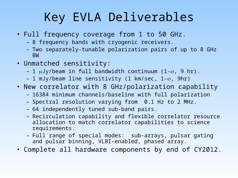
Key EVLA Deliverables• Full frequency coverage from 1 to 50 GHz.
– 8 frequency bands with cryogenic receivers.– Two separately-tunable polarization pairs of up to 8 GHz BW
• Unmatched sensitivity:– 1 Jy/beam in full bandwidth continuum (1-, 9 hr).– 1 mJy/beam line sensitivity (1 km/sec, 1-, 9hr)
• New correlator with 8 GHz/polarization capability– 16384 minimum channels/baseline with full polarization– Spectral resolution varying from 0.1 Hz to 2 MHz.– 64 independently tuned sub-band pairs. – Recirculation capability and flexible correlator resource allocation
to match correlator capabilities to science requirements. – Full range of special modes: sub-arrays, pulsar gating and pulsar
binning, VLBI-enabled, phased array.
• Complete all hardware components by end of CY2012.
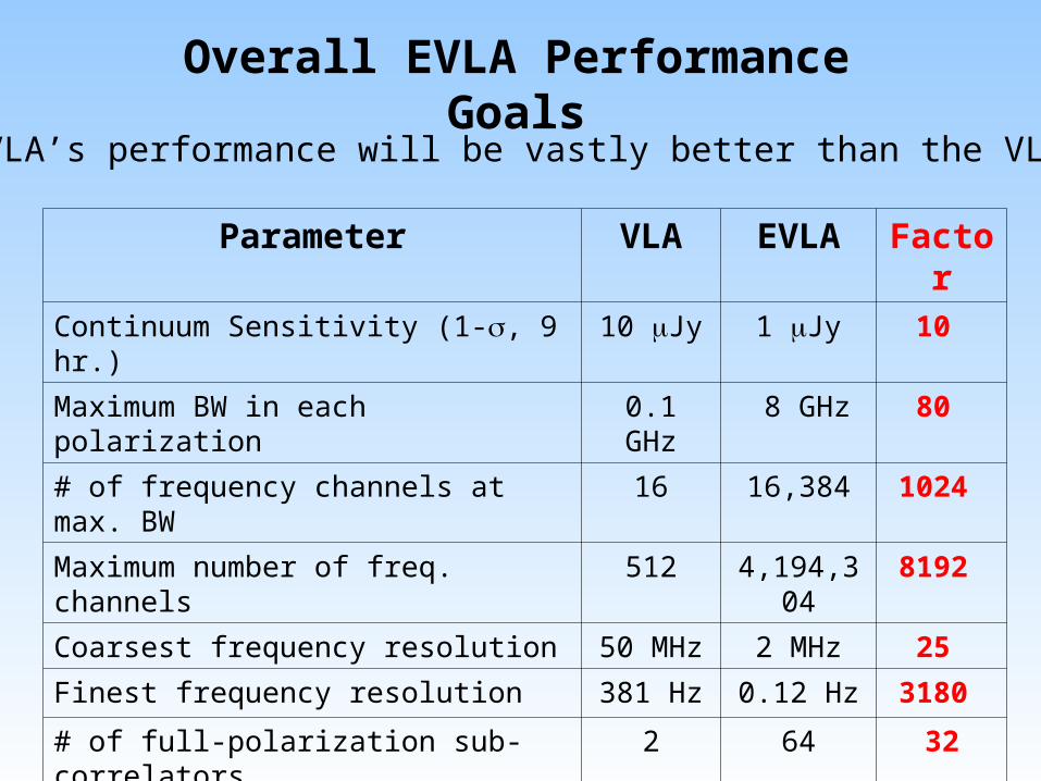
Overall EVLA Performance Goals
Parameter VLA EVLA Factor
Continuum Sensitivity (1-, 9 hr.) 10 Jy 1 Jy 10
Maximum BW in each polarization 0.1 GHz 8 GHz 80
# of frequency channels at max. BW 16 16,384 1024
Maximum number of freq. channels 512 4,194,304 8192
Coarsest frequency resolution 50 MHz 2 MHz 25
Finest frequency resolution 381 Hz 0.12 Hz 3180
# of full-polarization sub-correlators 2 64 32
(Log) Frequency Coverage (1 – 50 GHz)
22% 100% 5
The EVLA’s performance will be vastly better than the VLA’s:
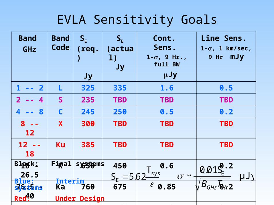
EVLA Sensitivity Goals
Band
GHz
Band Code
SE (req.) Jy
SE (actual)
Jy
Cont. Sens. 1-, 9 Hr., full BW
Jy
Line Sens. 1-, 1 km/sec, 9 Hr
mJy
1 -- 2 L 325 335 1.6 0.5
2 -- 4 S 235 TBD TBD TBD
4 -- 8 C 245 250 0.5 0.2
8 -- 12 X 300 TBD TBD TBD
12 -- 18 Ku 385 TBD TBD TBD
18 - 26.5 K 650 450 0.6 0.2
26.5 - 40 Ka 760 675 0.85 0.2
40 -- 50 Q 1200 1400 1.8 0.4Black: Final systems
Blue: Interim systems
Red: Under Design
Purple: Prototype
sys
E
T62.5S μJy
S01.0~ E
HrGHzTB
Snapshot of Project Status
• Project is going well• Budget: Financial health of the project is good
– Project contingency remains at historically high levels.– No plans to reduce scope of project
• Technical issues largely resolved• Project is on schedule:
– Antenna retrofits will be complete in Q3 2010 – Receiver installation complete in late 2012– Correlator scheduled for completion in Q1 2010– Software development on track to support
commissioning and early science
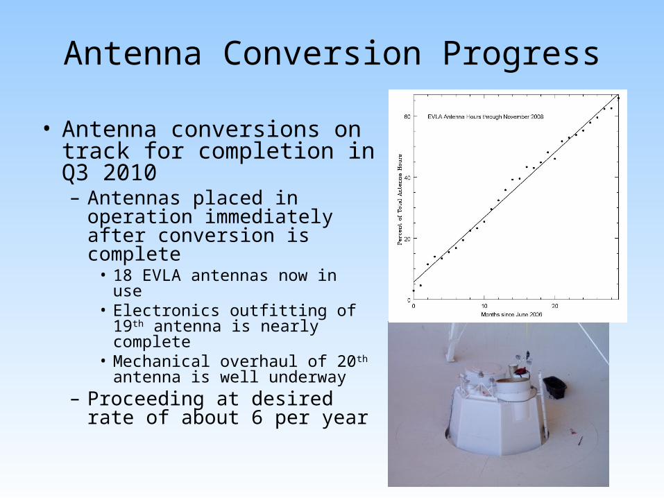
Antenna Conversion Progress
• Antenna conversions on track for completion in Q3 2010– Antennas placed in
operation immediately after conversion is complete
• 18 EVLA antennas now in use• Electronics outfitting of 19th
antenna is nearly complete• Mechanical overhaul of 20th
antenna is well underway– Proceeding at desired rate
of about 6 per year
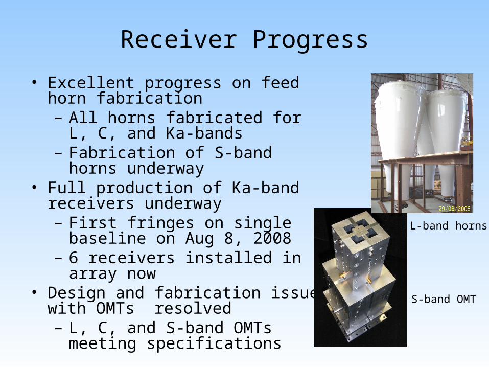
Receiver Progress
• Excellent progress on feed horn fabrication– All horns fabricated for L, C, and
Ka-bands– Fabrication of S-band horns
underway• Full production of Ka-band receivers
underway– First fringes on single baseline on
Aug 8, 2008– 6 receivers installed in array now
• Design and fabrication issues with OMTs resolved– L, C, and S-band OMTs meeting
specifications
S-band OMT
L-band horns
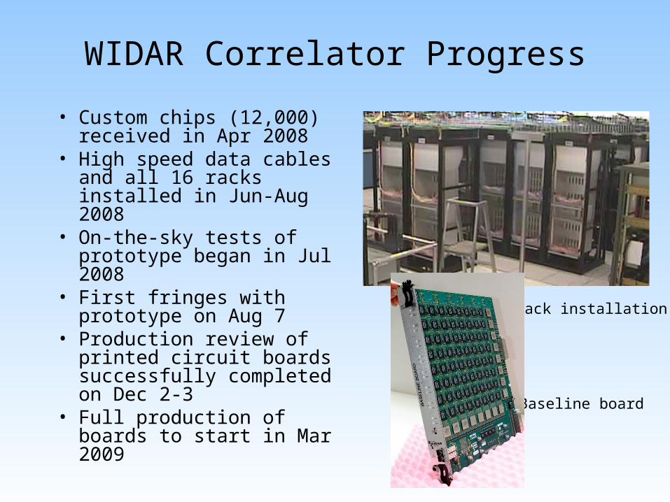
WIDAR Correlator Progress
• Custom chips (12,000) received in Apr 2008
• High speed data cables and all 16 racks installed in Jun-Aug 2008
• On-the-sky tests of prototype began in Jul 2008
• First fringes with prototype on Aug 7
• Production review of printed circuit boards successfully completed on Dec 2-3
• Full production of boards to start in Mar 2009
Baseline board
Rack installation
Additional Progress
• Wideband upgrade to LO/IF system started in June 2008– Production order of 3-bit, 4Gsps digitizers received
• Fiber infrastructure completed– Provides flexibility in locating antennas on the array
• Achieved goal of retiring VLA Modcomp control computers in Jun 2007.– 30 years worth of VLA M&C software replicated in
new suite of EVLA M&C software• Completed joint ALMA/EVLA definition of binary
data format for visibilities• Support for Ka-band observing with VLA
correlator built into Observation Preparation Tool
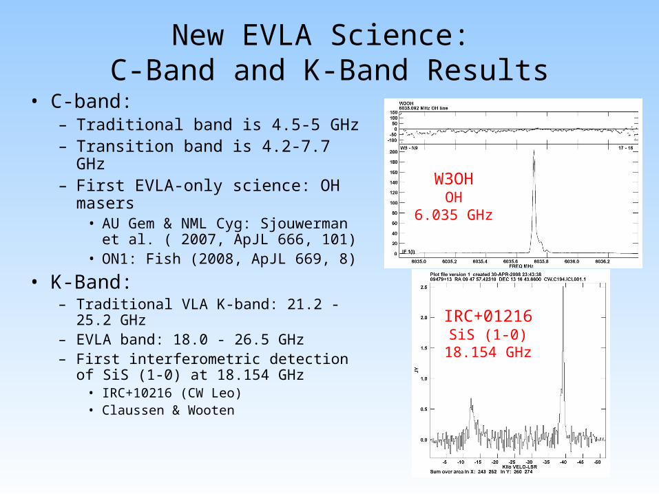
New EVLA Science: C-Band and K-Band Results
• C-band:– Traditional band is 4.5-5 GHz– Transition band is 4.2-7.7 GHz– First EVLA-only science: OH
masers• AU Gem & NML Cyg:
Sjouwerman et al. ( 2007, ApJL 666, 101)
• ON1: Fish (2008, ApJL 669, 8)
• K-Band:– Traditional VLA K-band: 21.2 - 25.2
GHz– EVLA band: 18.0 - 26.5 GHz– First interferometric detection of SiS
(1-0) at 18.154 GHz• IRC+10216 (CW Leo) • Claussen & Wooten
W3OHOH
6.035 GHz
IRC+01216SiS (1-0)
18.154 GHz
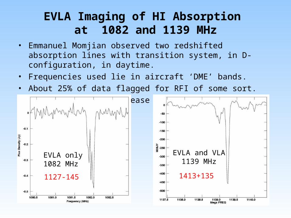
EVLA Imaging of HI Absorption at 1082 and 1139 MHz
• Emmanuel Momjian observed two redshifted absorption lines with transition system, in D-configuration, in daytime.
• Frequencies used lie in aircraft ‘DME’ bands. • About 25% of data flagged for RFI of some sort. • Sensitivity will increase dramatically with new OMT.
EVLA only1082 MHz
EVLA and VLA1139 MHz
1127-145 1413+135
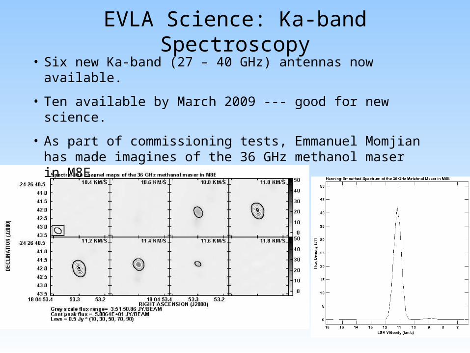
EVLA Science: Ka-band Spectroscopy• Six new Ka-band (27 – 40 GHz) antennas now available.
• Ten available by March 2009 --- good for new science.
• As part of commissioning tests, Emmanuel Momjian has made imagines of the 36 GHz methanol maser in M8E.
Other Unique EVLA Projects Now Scheduled
• Users have noted the increased frequency access:– 32 proposals accepted for C-band frequencies
outside the VLA 4.5 – 5.0 GHz window.• Galactic science proposals involve methanol, excited OH,
and formaldehyde masers in star forming regions.• Extragalactic science involves H2O masers near z = 2.
– 9 proposals accepted for expanded K-band coverage.• Science goals mostly involving high-redshift (z ~ 2 – 5)
molecular emission from young galaxies.
• With more frequencies opening up, the interest in observing in these new bands will increase.– Most significant new capability in 2009 will be
availability of Ka-band (26.5 – 40 GHz)
Antenna and Wideband Receiver Availability
• VLA antennas are being converted to EVLA antennas at a rate of 6/year.– 18 now converted. Conversion completed mid 2010.
• Upon conversion, EVLA antennas are outfitted with: – available wideband receivers (K, Q initially, now C, K, Ka, Q), – An existing VLA narrowband receiver, (X) – An ‘interim’ EVLA receiver – full tuning range, but limited
sensitivity and polarization (C, L initially, now only L), – No receiver (Ku, S)
• New receivers will be outfitted on EVLA antennas in the field, as designs are finalized, and production enables.
• Three bands still to be designed/tested: S, X, Ku• All receiver outfitting/retrofitting will be completed by end
of 2012.
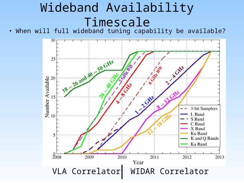
Wideband Availability Timescale• When will full wideband tuning capability be available?
VLA Correlator WIDAR Correlator
It’s Better Than It Looks!
• Wideband availability plot does not include capabilities of VLA antennas and ‘interim’ EVLA bands.
• Next two slides detail the capabilities growth for each band.
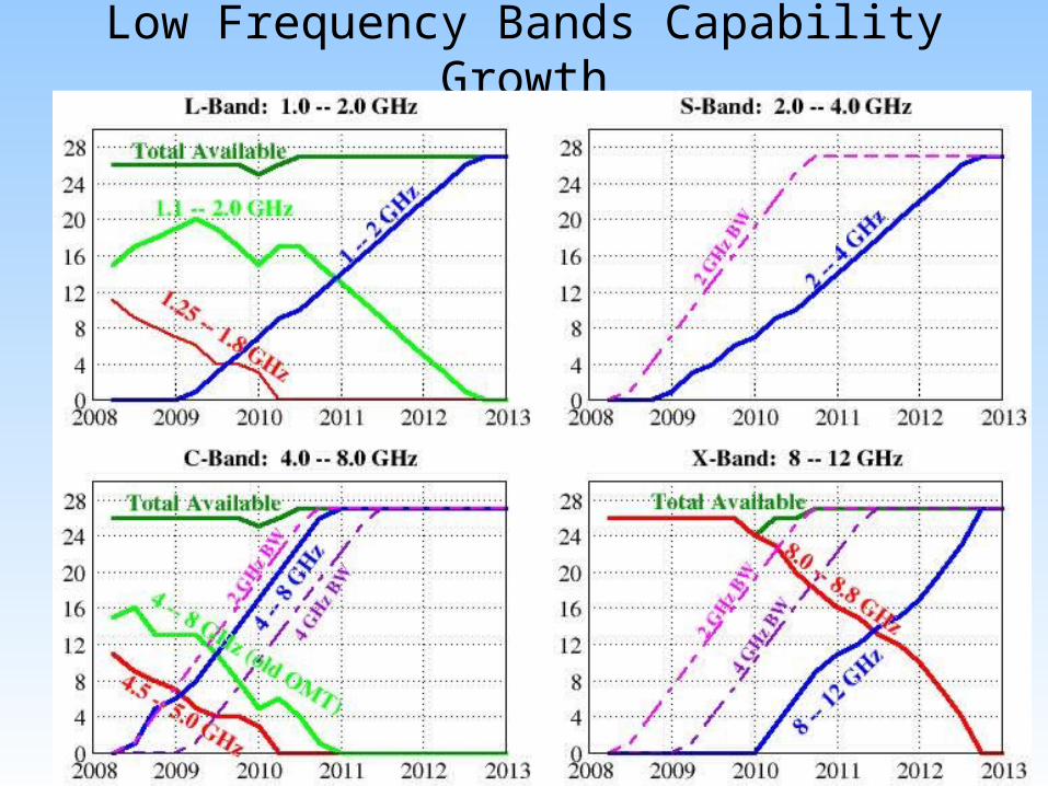
Low Frequency Bands Capability Growth
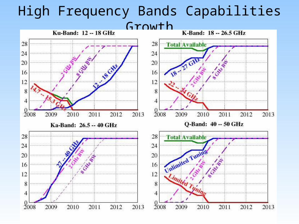
High Frequency Bands Capabilities Growth
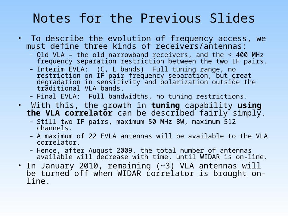
Notes for the Previous Slides
• To describe the evolution of frequency access, we must define three kinds of receivers/antennas:– Old VLA – the old narrowband receivers, and the < 400 MHz
frequency separation restriction between the two IF pairs. – Interim EVLA: (C, L bands) Full tuning range, no restriction on
IF pair frequency separation, but great degradation in sensitivity and polarization outside the traditional VLA bands.
– Final EVLA: Full bandwidths, no tuning restrictions. • With this, the growth in tuning capability using the VLA
correlator can be described fairly simply.– Still two IF pairs, maximum 50 MHz BW, maximum 512 channels.– A maximum of 22 EVLA antennas will be available to the VLA
correlator. – Hence, after August 2009, the total number of antennas available
will decrease with time, until WIDAR is on-line.• In January 2010, remaining (~3) VLA antennas will be
turned off when WIDAR correlator is brought on-line.
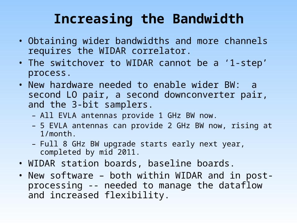
Increasing the Bandwidth
• Obtaining wider bandwidths and more channels requires the WIDAR correlator.
• The switchover to WIDAR cannot be a ‘1-step’ process. • New hardware needed to enable wider BW: a second LO
pair, a second downconverter pair, and the 3-bit samplers. – All EVLA antennas provide 1 GHz BW now.– 5 EVLA antennas can provide 2 GHz BW now, rising at 1/month. – Full 8 GHz BW upgrade starts early next year, completed by mid
2011.
• WIDAR station boards, baseline boards.• New software – both within WIDAR and in post-
processing -- needed to manage the dataflow and increased flexibility.
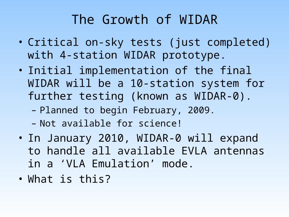
The Growth of WIDAR
• Critical on-sky tests (just completed) with 4-station WIDAR prototype.
• Initial implementation of the final WIDAR will be a 10-station system for further testing (known as WIDAR-0).– Planned to begin February, 2009. – Not available for science!
• In January 2010, WIDAR-0 will expand to handle all available EVLA antennas in a ‘VLA Emulation’ mode.
• What is this?
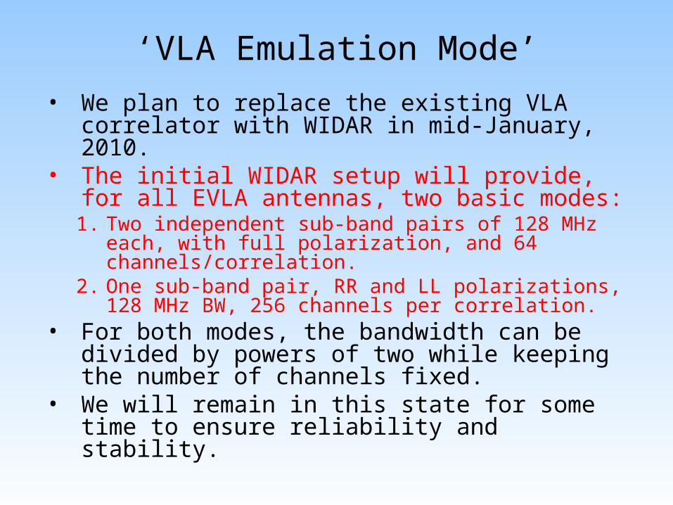
‘VLA Emulation Mode’
• We plan to replace the existing VLA correlator with WIDAR in mid-January, 2010.
• The initial WIDAR setup will provide, for all EVLA antennas, two basic modes: 1. Two independent sub-band pairs of 128 MHz each,
with full polarization, and 64 channels/correlation. 2. One sub-band pair, RR and LL polarizations, 128
MHz BW, 256 channels per correlation. • For both modes, the bandwidth can be divided
by powers of two while keeping the number of channels fixed.
• We will remain in this state for some time to ensure reliability and stability.
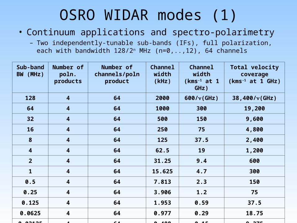
OSRO WIDAR modes (1)• Continuum applications and spectro-polarimetry
– Two independently-tunable sub-bands (IFs), full polarization, each with bandwidth 128/2n MHz (n=0,..,12), 64 channels
Sub-bandBW (MHz)
Number ofpoln.
products
Number ofchannels/poln
product
Channelwidth (kHz)
Channel width
(kms-1 at 1 GHz)
Total velocity coverage
(kms-1 at 1 GHz)
128 4 64 2000 600/(GHz) 38,400/(GHz)
64 4 64 1000 300 19,200
32 4 64 500 150 9,600
16 4 64 250 75 4,800
8 4 64 125 37.5 2,400
4 4 64 62.5 19 1,200
2 4 64 31.25 9.4 600
1 4 64 15.625 4.7 300
0.5 4 64 7.813 2.3 150
0.25 4 64 3.906 1.2 75
0.125 4 64 1.953 0.59 37.5
0.0625 4 64 0.977 0.29 18.75
0.03125 4 64 0.488 0.15 9.375
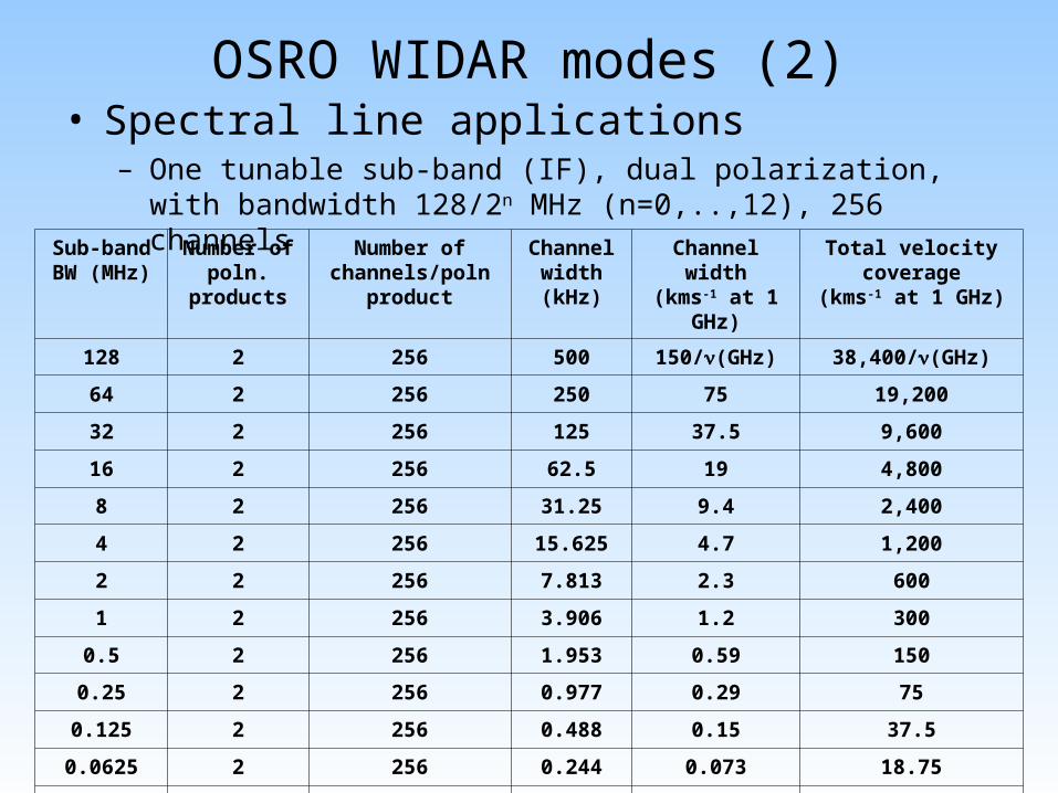
• Spectral line applications– One tunable sub-band (IF), dual polarization, with bandwidth
128/2n MHz (n=0,..,12), 256 channels
OSRO WIDAR modes (2)
Sub-bandBW (MHz)
Number ofpoln.
products
Number ofchannels/poln
product
Channelwidth (kHz)
Channel width(kms-1 at 1
GHz)
Total velocity coverage
(kms-1 at 1 GHz)
128 2 256 500 150/(GHz) 38,400/(GHz)
64 2 256 250 75 19,200
32 2 256 125 37.5 9,600
16 2 256 62.5 19 4,800
8 2 256 31.25 9.4 2,400
4 2 256 15.625 4.7 1,200
2 2 256 7.813 2.3 600
1 2 256 3.906 1.2 300
0.5 2 256 1.953 0.59 150
0.25 2 256 0.977 0.29 75
0.125 2 256 0.488 0.15 37.5
0.0625 2 256 0.244 0.073 18.75
0.03125 2 256 0.122 0.037 9.375
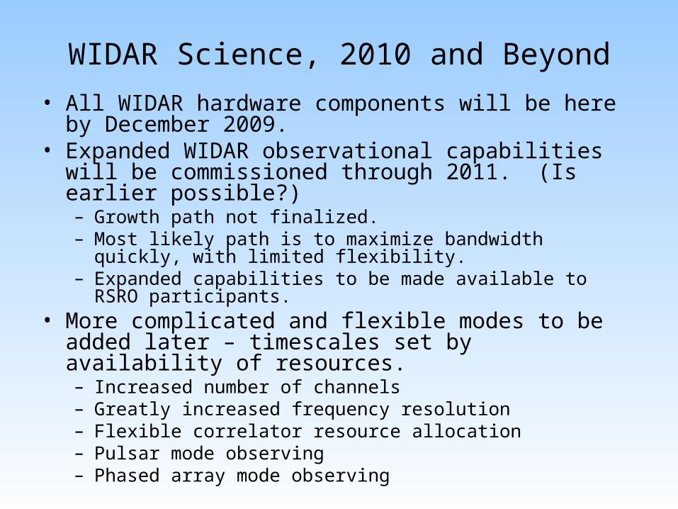
WIDAR Science, 2010 and Beyond
• All WIDAR hardware components will be here by December 2009.
• Expanded WIDAR observational capabilities will be commissioned through 2011. (Is earlier possible?)– Growth path not finalized.– Most likely path is to maximize bandwidth quickly, with limited
flexibility. – Expanded capabilities to be made available to RSRO
participants.• More complicated and flexible modes to be added later –
timescales set by availability of resources. – Increased number of channels– Greatly increased frequency resolution– Flexible correlator resource allocation– Pulsar mode observing– Phased array mode observing
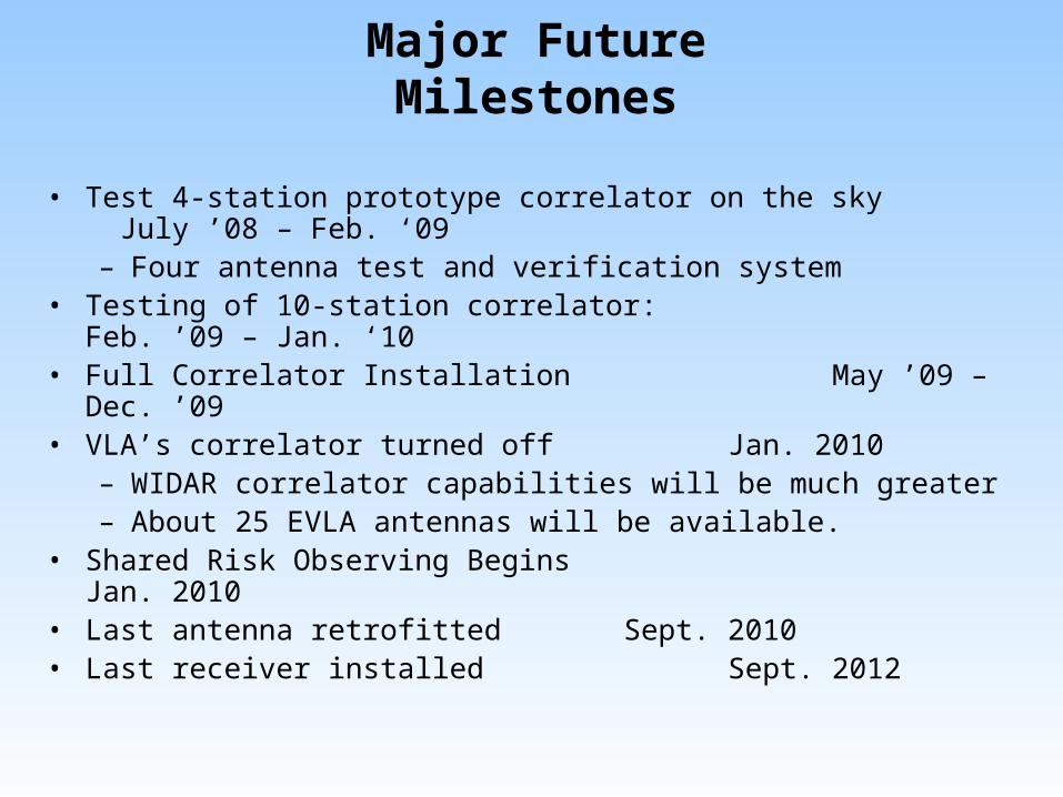
Major Future Milestones
• Test 4-station prototype correlator on the sky July ’08 – Feb. ‘09– Four antenna test and verification system
• Testing of 10-station correlator: Feb. ’09 – Jan. ‘10
• Full Correlator Installation May ’09 – Dec. ’09
• VLA’s correlator turned off Jan. 2010 – WIDAR correlator capabilities will be much greater – About 25 EVLA antennas will be available.
• Shared Risk Observing Begins Jan. 2010• Last antenna retrofitted Sept. 2010• Last receiver installed Sept. 2012