Embed Size (px)
Citation preview

1
SATRA Electronics
PWS 10/07/09

2
Antenna (Downhole) CablesCables shipped cut-to-length, terminated and wound (not on spools)Downhole cables: ~14” diameter winding with (3) removable tiesDelay loops: ~14” diameter winding with (3) cable ties
3
Antenna Cable Breakouts and Connectors
30m15m 5m
SurfaceAnchor point
Taped to IC cable
15m15m
F-Male Crimp NK# 92N5307
F-Female: F-Female adapter NK# 79K4850
F-Female: BNC-Male adapter DK# 501-1155-ND
Outside Endof Deployment
Winding
UHF-Female: UHF-Female adapter DK# 367-1083-ND
BNC-Female: UHF-Male adapter DK# CPAD500-ND
DK= Digi-KeyNK= NewarkMS= Mouser
Delay and AttenuationMatching loop:Delay length = SDual RG6 cut length = S/2Placed at top of hole
“s”
Belden 1843A75Ω Dual RG6:-0.045” BCCS-RG6 (INNER)-RG6 (OUTER)
To DAQ Suitcaseat top of hole
TopBreakout~4” pigtail
BottomBreakout~4” pigtail
Belden 1152ATFE RG6 Jumpers
75Ω 36” long
5m

4
Antenna DeploymentSame configuration for Top and Bottom
AluminumBailing WireSpacer
=Driller Tape
Dual CoaxialBelden 1843A
Maple Dowel4 ft long x ¾” ODMcMaster 97015K19
Brackets 4” RAMcMaster 1556A17
Plastic Clamp (2)Black AcetalMcMaster 7429K47
Plywood Disk ¼”12” Diameter. w/ (4) 10-32 T-Nuts
Diamond Corp.D220 Discone-first whip element only
Deployment Construction Detail
Belden 1152ATFE RG6 Jumpers75Ω 36” long

5
2 channel DOM MainBoard DAQ
Noise input “A”
CommunicationsAnd Power
Delay Boards
Main Board “U”
Main Board Interface PCB (2 ea)
Pulse input “B”
Pulse input “A”
Noise input “B”Main Board “T”

6
DOM MB DAQ WIRING
Last Modified: REV
PAGE OF
Page Created:Board File:Size:
IceCube Research Center222 W. Washington Avenue, Madison, Wisconsin 53703
Friday, September 18, 2009
num ct
Thursday, July 02, 2009
DOM MB DAQ Channel ASSY
<Board Name>3
<File>
A
PMT InputSMB JackAMP 414244-1
TB1GND
TB3TB2
COMM+COMM-
J5WM2901-ND
123
J4WM2902-ND
1234
LC0_POSLC0_NEGLC1_POSLC1_NEG
TB10TB9TB8TB7
SMA-M to BNC-M 12" long Assy
Transformer Couplingfor Inversion and Isolation
J1 Ch 2WM2901-ND
123
SMB JackAMP 414244-1A4047-ND
Coaxial Cable Assembly:SMB-75 Ohm Right Angle toSMB-75 Ohm Right Anglee.g Newark 77M731112" length of RG179 or RG187Note SMB *50 Ohm* is wrong type!
J2WM2900-ND
12
J3WM2900-ND
12
BNC Feedthruon Front Panel
MB Interface Card2" x 3"
PxWM2900-ND
12
PxWM2900-ND
12
All Hookup Wire AWG#22 TFE
J1 Ch 1WM2901-ND
123
Quad Connectoron Front Panel
BLKRED
YELVIO
YEL
Twist Top and Bottom Pairs
VIOBLUBRN
YELVIO
LC Jumpers Twisted pairs
J6WM2900-ND
12JP2-1
JP2-2
5VanalogPWR_GND
BLKRED
ORGGRA
J3
SMA VERT
J7WM2900-ND
12
C16.7
J1SMA VERT
L1
66uH
J2SMB 75 ohm
GRN
GRN
SMA-F to SMA-M12" long Assy
SMA Feedthruon Front Panel
TP5-1WHT
TP5-2GRA
Remove R7 from MBto Disconnect Barometer
J3MS3112E14-5P
ABCDE
T1Transformer_2_RF
1
3 4
6
C20.1
Channel 1= MB in ChassisChannel 2= MB attached to Lid
SMA-M(RA):SMA-M(RA) 12” cableDK J4412-ND SMA-F:BNC-M adapterMS 523-242103 NK 80K0205
SMA-M(RA):SMA-F(BH) 12” cableDK J7212-ND
7
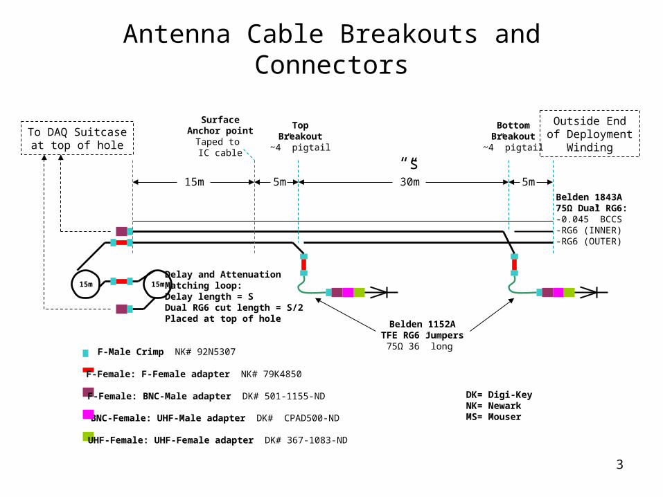
Suitcase Interconnects
Ch A
Ch B
Ch A
Ch B
= SMA-F
= BNC-F
= MS3112-E14-5P
450 MHz TDAIN OUTREF
= MS3116-F14-5S
= MS3114-F14-5P
“WP0”
“WP1”
SATRA Y Adapter
(Ch4)
(Ch3)
(Ch2)
(Ch1)
Front End Assembly (2 or 4)
BNC-F:BNC-F Feedthrough, DK ARF1735-ND
BNC-M:SMA-F Adapter, NK 92C7248 MS 523-242103
SMA-M:SMA-M Coupler, NK 92H4682, DK ACX1240-ND
SMA-M(RA):SMA-M(RA) 12” Cable, DK J4412-ND
Mounted in Suitcase Wall After Shipment
11
1
Optional 2nd DAQ
8
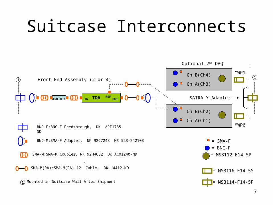
MB Interface PCB
Last Modified: REV
PAGE OF
Page Created:Board File:Size:
IceCube Research Center222 W. Washington Avenue, Madison, Wisconsin 53703
Friday, September 18, 2009
1 1
Friday, August 07, 2009
DOM Mainboard Interface PCB
<Board Name>1
<File>
A
C34.7uF
R6 0
L422uH
1 2
R5NL
R7NL
P6MB +5
12
P5MB COMMS
123
P1COMMS1
23
TB10
TB7TB8TB9P4
MB LC
1234
P2LC01
2
P3LC11
2
LC0_POSLC0_NEG
LC1_POSLC1_NEG
TB1
C4
0.1uF
TP5-1
TB2
TP5-2
TB3
NEGPOSGND
J2SMB 75 ohm
SMB JackAMP 414244-1A4047-ND
JP2-1JP2-2
L622uH
1 2
R2 0
L322uH
1 2
( MB Pressure ADC )
L222uH
1 2
L5150nH
1 2
FB1Z=40
T1T1.5-1-KK81+
1
3 4
6R8NL
J3SMA Vert
C20.1uF
C10.1uF
R1 0
P7MB MON
12
L122uH
1 2
TP1
J1SMA Vert
TP2 TP3
R3 NL
R4 NL
To TDA (DC and Sig)
To TDA REF OUT
9
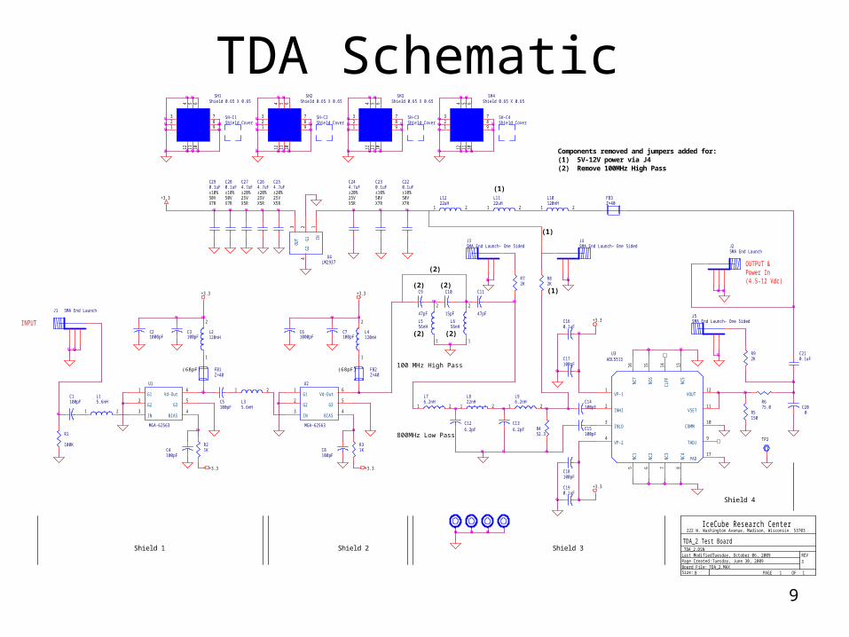
TDA SchematicSH2
Shield 0.65 X 0.65
123
4 5 6
789
101112 Components removed and jumpers added for:(1) 5V-12V power via J4(2) Remove 100MHz High Pass
R92K
R1
100K
C126.2pF
INPUT
SH3Shield 0.65 X 0.65
123
4 5 6
789
101112
J1 SMA End Launch
Shield 4
R5150
SH4Shield 0.65 X 0.65
123
4 5 6
789
101112
J3SMA End Launch- One Sided
R82K
SH-C4Shield Cover
J4SMA End Launch- One Sided
J5SMA End Launch- One Sided
SH1Shield 0.65 X 0.65
123
4 5 6
789
101112
TP2
Last Modified: REV
PAGE OF
Page Created:Board File:Size:
IceCube Research Center222 W. Washington Avenue, Madison, Wiscons in 53703
Tuesday, October 06, 2009
1 1
Tuesday, June 30, 2009
TDA_2 Test Board
TDA_2.MAX3
TDA_2.DSN
B
U1
MGA-62563
G11
G22
IN3
BIAS4
G35
Vd-Out6
R675.0
L15.6nH
1 2
L2120nH
1
2
C1100pF
C4100pF
C3100pF
C21000pF
C5100pF
R21K
L76.2nH
1 2
C210.1uF
Shield 2Shield 1 Shield 3
+3.3
(68pF)
L1222uH
1 2
L1122uH
1 2
L10120nH
1 2
U3ADL5513
VP-11
INHI2
INLO3
VP-24
NC
716
NC
615
CLP
F14
NC
513
VOUT12
VSET11
COMM10
TADJ9
NC
15
NC
26
NC
37
NC
48
PAD17
C14100pF
R452.3
C15100pF
C190.1uF
C160.1uF
C200
C220.1uF±10%50VX7R
SH-C1Shield Cover
+3.3
C136.2pF
C230.1uF±10%50VX7R
L656nH
1
2
+3.3
+3.3
SH-C2Shield Cover
OUTPUT &Power In(4.5-12 Vdc)
J2SMA End Launch
SH-C3Shield Cover
FB3Z=40
FB1Z=40
FB2Z=40
C7100pF
C8100pF
+3.3
U2
MGA-62563
G11
G22
IN3
BIAS4
G35
Vd-Out6
L4120nH
1
2
(68pF)
C61000pF
L35.6nH
1 2
R31K
U4LM2937
IN1
G1
2O
UT
3
G2
4
+3.3
C280.1uF±10%50VX7R
C290.1uF±10%50VX7R
+3.3
C11
47pF
C17100pF
C18100pF
C274.7uF±20%25VX5R
L556nH
1
2
(1)C264.7uF±20%25VX5R
C254.7uF±20%25VX5R
C244.7uF±20%25VX5R
(1)
100 MHz High Pass
(2)
800MHz Low Pass
R72K
C9
47pF
(2)
(2)
C10
15pF
(2)
L822nH
1 2
(1)
L96.2nH
1 2
(2)
10
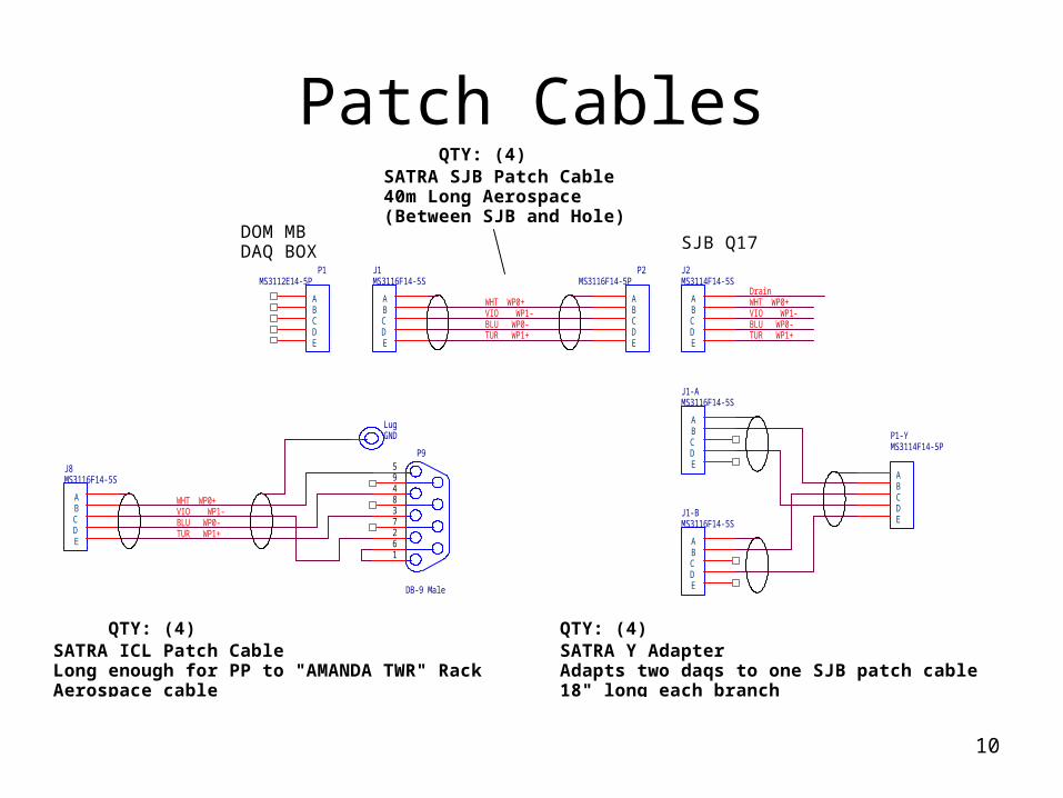
Patch Cables
J2MS3114F14-5S
ABCDE
SJB Q17
BLU WP0-TUR WP1+
WHT WP0+VIO WP1-
P2MS3116F14-5P
ABCDE
P1MS3112E14-5P
ABCDE
J1MS3116F14-5S
ABCDE
DOM MBDAQ BOX
WHT WP0+VIO WP1-BLU WP0-TUR WP1+
SATRA SJB Patch Cable40m Long Aerospace(Between SJB and Hole)
P1-YMS3114F14-5P
ABCDE
J1-AMS3116F14-5S
ABCDE
J1-BMS3116F14-5S
ABCDE
QTY: (4)
SATRA ICL Patch CableLong enough for PP to "AMANDA TWR" RackAerospace cable
QTY: (4)
LugGND
SATRA Y AdapterAdapts two daqs to one SJB patch cable18" long each branch
J8MS3116F14-5S
ABCDE
VIO WP1-WHT WP0+
TUR WP1+BLU WP0-
QTY: (4)
P9
DB-9 Male
1
2
3
4
5
6
7
8
9
Drain
11
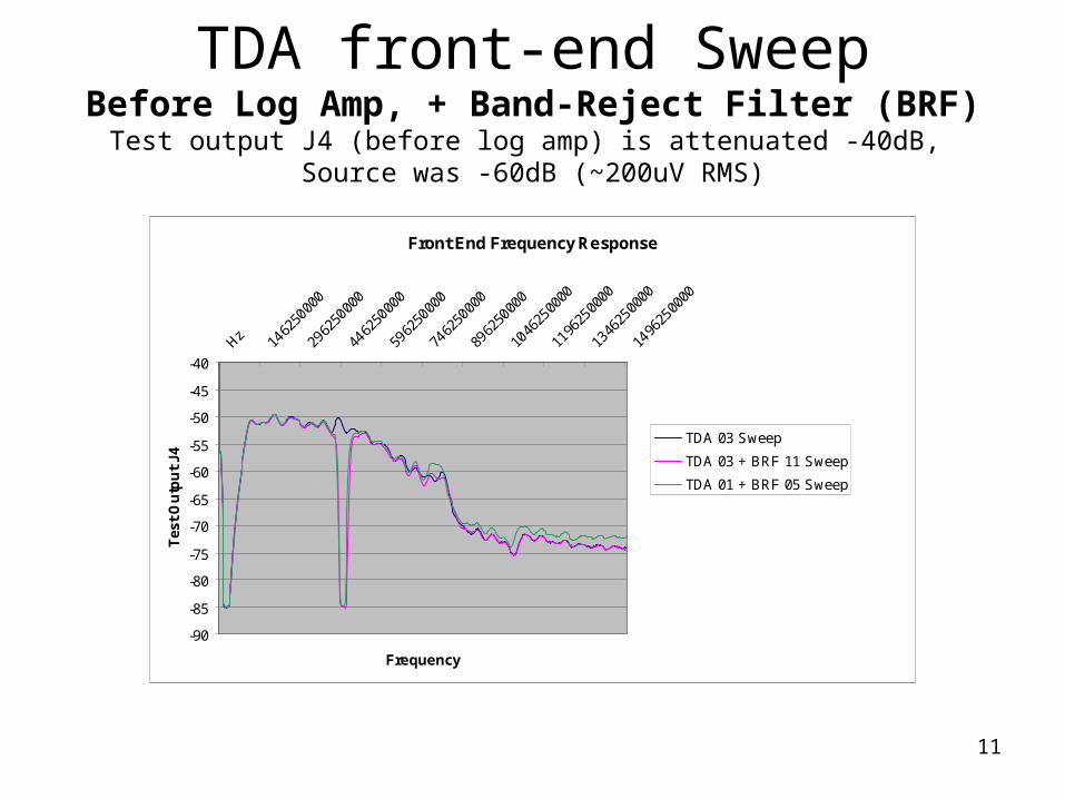
TDA front-end SweepBefore Log Amp, + Band-Reject Filter (BRF)
Test output J4 (before log amp) is attenuated -40dB, Source was -60dB (~200uV RMS)
Front End Frequency Response
-90
-85
-80
-75
-70
-65
-60
-55
-50
-45
-40Hz 14
6250
000
2962
5000
0
4462
5000
0
5962
5000
0
7462
5000
0
8962
5000
0
1046
2500
00
1196
2500
00
1346
2500
00
1496
2500
00
Frequency
Tes
t O
utp
ut
J4
TDA 03 Sweep
TDA 03 + BRF 11 Sweep
TDA 01 + BRF 05 Sweep
12
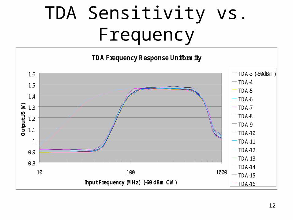
TDA Sensitivity vs. Frequency
TDA Frequency Response Uniformity
0.8
0.9
1
1.1
1.2
1.3
1.4
1.5
1.6
10 100 1000
Input Frequency (MHz) (-60 dBm CW)
Out
put J
5 (V
)
TDA-3 (-60dBm)
TDA-4
TDA-5
TDA-6
TDA-7
TDA-8
TDA-9
TDA-10
TDA-11
TDA-12
TDA-13
TDA-14
TDA-15
TDA-16
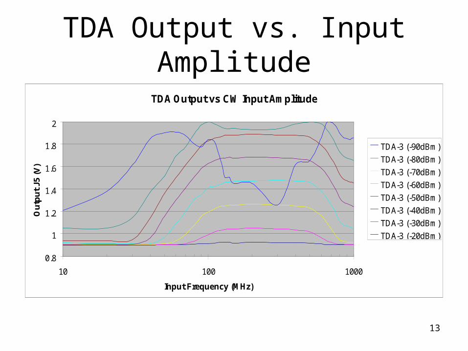
13
TDA Output vs. Input Amplitude
TDA Output vs CW Input Amplitude
0.8
1
1.2
1.4
1.6
1.8
2
10 100 1000
Input Frequency (MHz)
Ou
tpu
t J5
(V
)
TDA-3 (-90dBm)
TDA-3 (-80dBm)
TDA-3 (-70dBm)
TDA-3 (-60dBm)
TDA-3 (-50dBm)
TDA-3 (-40dBm)
TDA-3 (-30dBm)
TDA-3 (-20dBm)