Embed Size (px)
Citation preview

IMP / UMPR107
SECT
ION
1
1


1-3
Our Most Important Connection is with You.™
Go online for data sheets & assembly instructions. Visit www.radiall.com and enter the part number.
Introduction ........................................................................................................................................................... 1-4 to 1-6
IMP
Characteristics .................................................................................................................................................................1-7Board to board connectors ..............................................................................................................................................1-8Receptacle packaging ......................................................................................................................................................1-9Assembly instructions ........................................................................................................................................ 1-9 to 1-10
UMP
Characteristics ...............................................................................................................................................................1-11Receptacles ....................................................................................................................................................................1-12Pigtails ...........................................................................................................................................................................1-12Cable assemblies ...........................................................................................................................................................1-12Tools and accessories ....................................................................................................................................................1-13Receptacle packaging ....................................................................................................................................................1-14Assembly instructions ...................................................................................................................................... 1-14 to 1-15Connection and extraction .............................................................................................................................................1-16
SECT
ION
1 TA
BLE
OF C
ONTE
NTS
Contents
1-4
Our Most Important Connection is with You.™
Go online for data sheets & assembly instructions. Visit www.radiall.com and enter the part number.
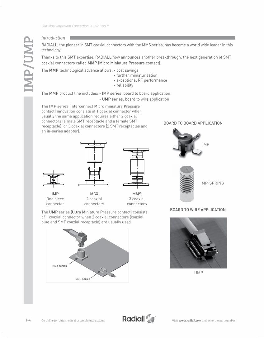
RADIALL, the pioneer in SMT coaxial connectors with the MMS series, has become a world wide leader in this technology.
Thanks to this SMT expertise, RADIALL now announces another breakthrough: the next generation of SMT coaxial connectors called MMP (Micro Miniature Pressure contact).
The MMP technological advance allows: - cost savings - further miniaturization - exceptional RF performance - reliability
The MMP product line includes: - IMP series: board to board application - UMP series: board to wire application
The IMP series (Interconnect Micro miniature Pressure contact) innovation consists of 1 coaxial connector when usually the same application requires either 2 coaxial connectors (a male SMT receptacle and a female SMT receptacle), or 3 coaxial connectors (2 SMT receptacles and an in-series adapter).
BOARD TO BOARD APPLICATION
BOARD TO WIRE APPLICATION
IMPOne piece connector
MCX 2 coaxial
connectors
MMS3 coaxial
connectors
The UMP series (Ultra Miniature Pressure contact) consists of 1 coaxial connector when 2 coaxial connectors (coaxial plug and SMT coaxial receptacle) are usually used.
IMP-SPRIng
UMP
IMP/
UMP
MCX series
UMP series
IMP
Introduction
1-5
Our Most Important Connection is with You.™
Go online for data sheets & assembly instructions. Visit www.radiall.com and enter the part number.
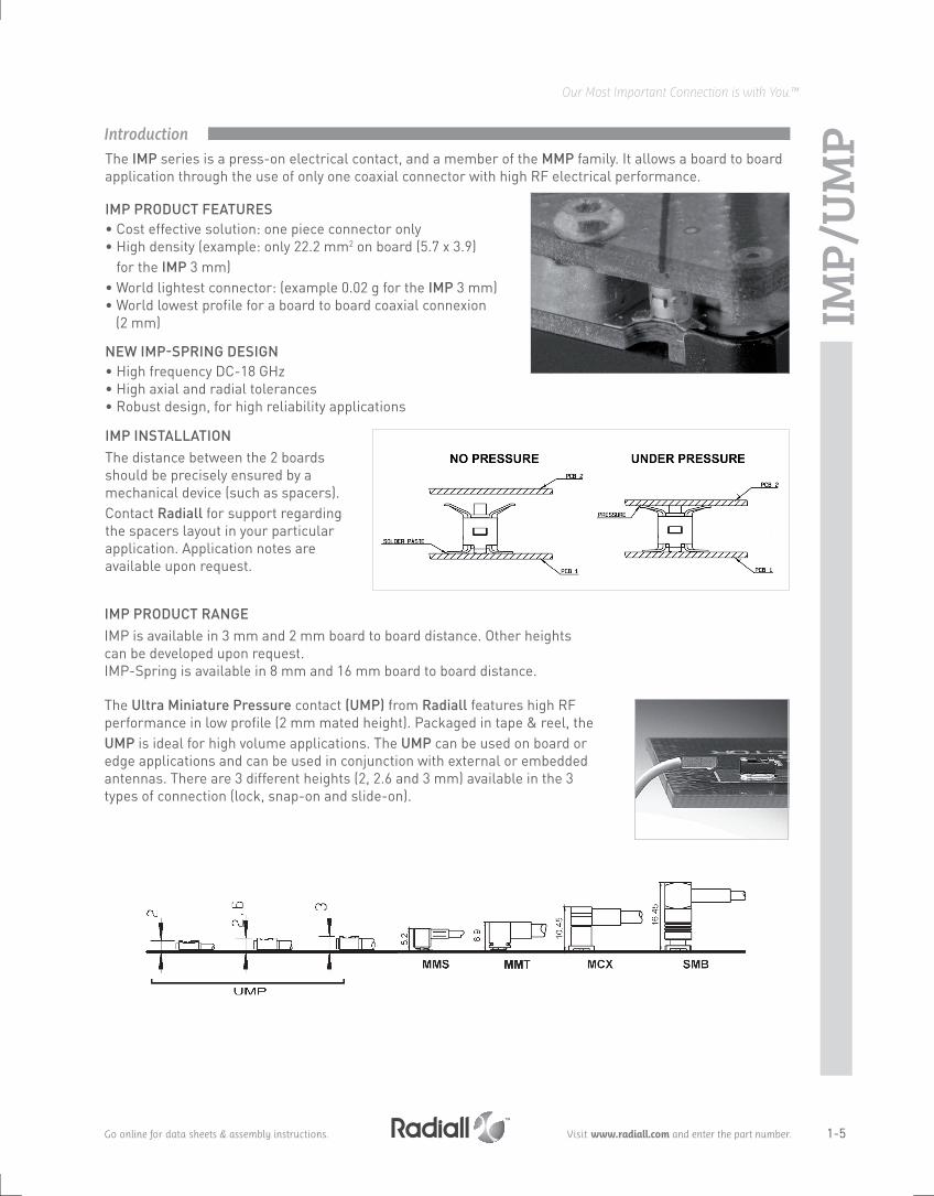
The IMP series is a press-on electrical contact, and a member of the MMP family. It allows a board to board application through the use of only one coaxial connector with high RF electrical performance.
IMP PRODUCT fEATURES• Cost effective solution: one piece connector only• High density (example: only 22.2 mm2 on board (5.7 x 3.9)
for the IMP 3 mm)• World lightest connector: (example 0.02 g for the IMP 3 mm)• World lowest profile for a board to board coaxial connexion (2 mm)
NEW IMP-SPRINg DESIgN• High frequency DC-18 GHz• High axial and radial tolerances• Robust design, for high reliability applications
The Ultra Miniature Pressure contact (UMP) from Radiall features high RF performance in low profile (2 mm mated height). Packaged in tape & reel, the UMP is ideal for high volume applications. The UMP can be used on board or edge applications and can be used in conjunction with external or embedded antennas. There are 3 different heights (2, 2.6 and 3 mm) available in the 3 types of connection (lock, snap-on and slide-on).
IMP/
UMP
IMP INSTALLATIONThe distance between the 2 boards should be precisely ensured by a mechanical device (such as spacers). Contact Radiall for support regarding the spacers layout in your particular application. Application notes are available upon request.
IMP PRODUCT RANgEIMP is available in 3 mm and 2 mm board to board distance. Other heights can be developed upon request.IMP-Spring is available in 8 mm and 16 mm board to board distance.
Introduction

1-6
Our Most Important Connection is with You.™
Go online for data sheets & assembly instructions. Visit www.radiall.com and enter the part number.
PICK AND PLACE & PACKAgINg• The design is adapted to automated pick and place machines. The footprint
of IMP or UMP allows video positioning by using the component's shadow to facilitate its placement.
• Packaging: tape and reels of 100, 600, 2500 or 3500 pieces. IMP-Spring is bulk packaged.
UMP MAIN PRODUCT INTEREST• Low profile: 2 mm, 2.6 mm and 3 mm• Small space for connection: needs only 2 mm of height• Cost effective solution: 1 coax connector only• Coupling mechanism choice (lock, snap-on, slide-on)• Large cable range from 0.8 to 2.6 mm
UMP TyPE Of MATINg:Only 1 coaxial connectorWith 3 mating types:• capitalize lock: - can only be disconnected using a tool
- number of matings 100 - withstands severe vibrations
• capitalize snap-on: - number of matings 3000• capitalize slide-on: - number of matings 10000
- for test applications
Plugs exist in the 3 types of mating (lock, snap-on and slide-on).
Insulator
Outer contact
Lock
Snap-on
Slide-on
Center contact
APPLICATIONS:
IMP and UMP series can be used on board-to-board (or board-to-antenna) applications:• WLAN• Mobile phone• GPS receivers• Automotive• Handheld radios• RFID
2 m
m m
ated
hei
ght
IMP/
UMP Introduction

1-7
Our Most Important Connection is with You.™
Go online for data sheets & assembly instructions. Visit www.radiall.com and enter the part number.
IMP
Values/remarks
ELECTRICAL CHARACTERISTICS (see note) IMP IMP-sPrIng
Impedance 50Ω 50Ω 50Ω
Frequency range DC-6 GHz DC-6 GHz DC-18 GHz
V.S.W.R. 1.3 Max 1.3 Max 1.5 MaxInsertion Loss (dB) 0.2 √F (GHz) 0.15 up to 3 GHz 0.2 √F (GHz)Insulation resistance 3000 MΩ 3000 MΩ
Contact resistance (depending on PC board) Center contact Outer contact
60 mΩ10 mΩ
(gold plated target board)20 mΩ10 mΩ
(gold plated target board)15 mΩ2 mΩ
Working voltage in VRMS 100 100
Dielectric withstanding voltage in VRMS 350 350
Power at sea level, at 20°C, 3 GHz 20 W 20 W
MECHANICAL CHARACTERISTICS (see note)Durability > 20 > 50 > 50
Weight (g) 0.02 2.6 1.4
Axial misalignment from nominal board to board distance in mm (inch)
± 0.2 (.008) ± 1 (.04) ± 0.5 (.02)
radial misalignment in mm (inch) 0.2 (.008) 1 (.04) 0.7 (.027)
Tilt tolerance (angle between boards) not specified 1° not specified
ENVIRONMENTAL CHARACTERISTICS Temperature range -40 / +90°C -50 / +125°C -50 / +125°C
MATERIALSBody
Beryllium copper Beryllium copper, brassContact
Insulator Polyethercetone PTFE, Peek
PLATINGBody
goldgold
goldContact nPgR
Note:
Tested per CECC 22000
V.S.W.R
All dimensions are given in mm.
Frequency Typical VsWr IMP
1 GHz 1.01
2 GHz 1.04
3 GHz 1.06
4 GHz 1.08
5 GHz 1.08
Frequency Typical VsWr IMP-sPrIng 18 gHz
nominal position Max radial misalignment
6 GHz 1.02 1.02
12 GHz 1.08 1.10
18 GHz 1.12 1.40
Characteristics

1-8
Our Most Important Connection is with You.™
Go online for data sheets & assembly instructions. Visit www.radiall.com and enter the part number.
IMP SMT CONNECTORS
SPRING LOAdEd CONNECTORS
TEST BOARdS
Fig. 1
Fig. 1
Part number Height (mm) Fig Packaging reel dimensions A (mm) Assembly instructions
R107 064 080 2 1 Reel of 3500 330 M01
R107 064 9003 2
Reel of 2500 330
R107 064 920 Reel of 100 180
Part number Fig Frequency range Axial tolerance in mm (inch)
nominal board to board distance in mm (inch) Packaging
R107 194 000 1 DC-6 GHz ± 1 (.04) 14 (.551)Bulk 100
R107 184 000 2 DC-18 GHz ± 0.5 (.02) 8.1 (.319)
Available upon request, please contact us.
This connector can also be developed upon request with other heights, in order to adjust space between PCB. Please consult us.
These surface mount (SMT) coaxial connectors are designed to handle large mechanical misalignment between two printed circuit boards. A single connector achieves the board to board coaxial interconnection. The connector is soldered to the main PCB and the top board acts like the counterpart with its dedicated “target” pad.
Other heights and packaging options can be designed upon request.
Board to board connectors
Fig. 2
Fig. 2

1-9
Our Most Important Connection is with You.™
Go online for data sheets & assembly instructions. Visit www.radiall.com and enter the part number.
ACCORDINg TO IEC 286-3 STANDARDMATERIALS Reel: polyester Carrier tape: antistatic PETg (polyester) Cover tape: polyester
SOLDERIng PATTERn
B VIEW B VIEW
Part number
R107 064 900R107 064 920
Part number
R107 064 900R107 064 920
Part number
R107 064 080
Part number
R107 064 080
IMP
M01
COnTACT PATTERn
Metallization
Land for solder paste (area free of vamish)
Metallization
Contact area (area free of any surface contaminant)
B view
Receptacle packaging
Assembly instructions
1-10
Our Most Important Connection is with You.™
Go online for data sheets & assembly instructions. Visit www.radiall.com and enter the part number.
IMP
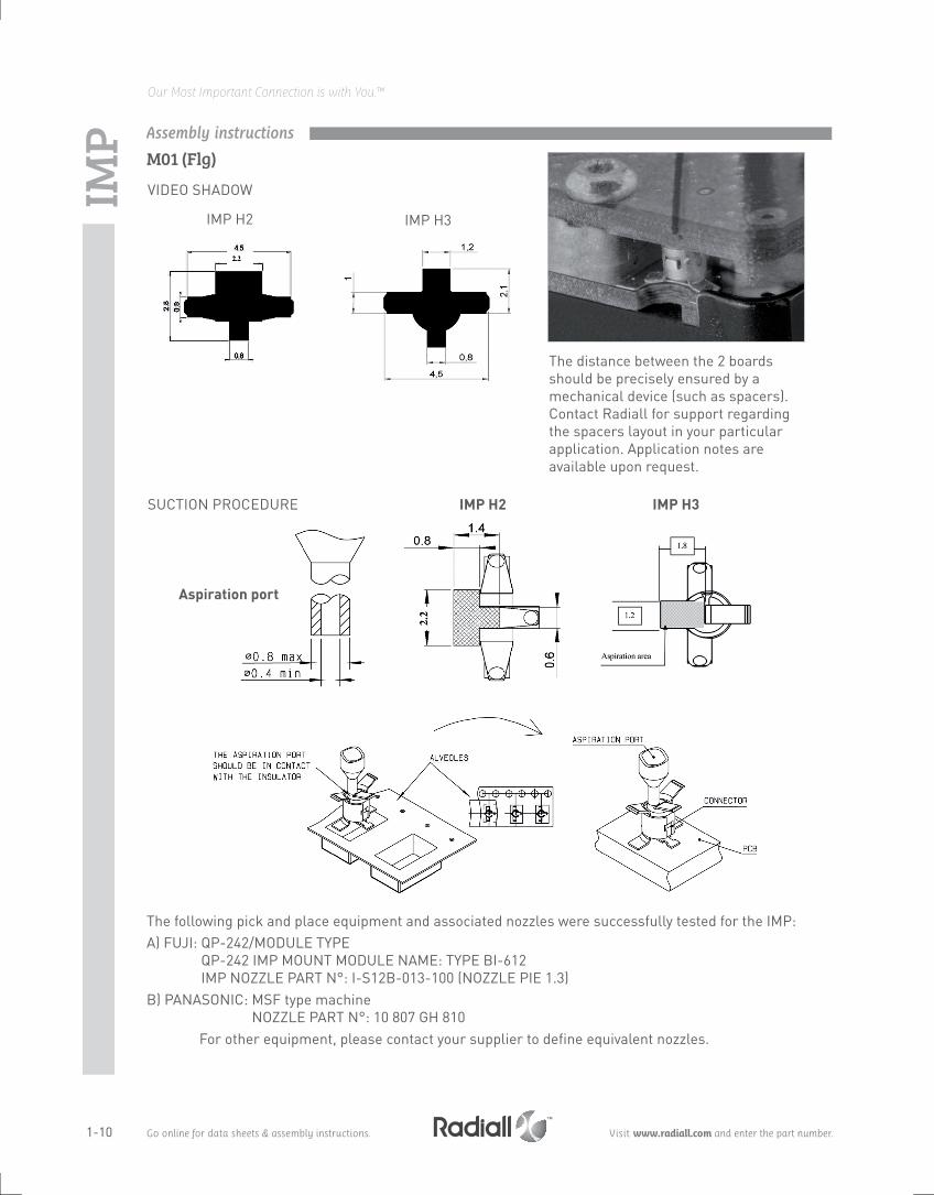
VIDEo SHADoW
SUCTIOn PROCEDURE
The distance between the 2 boards should be precisely ensured by a mechanical device (such as spacers). Contact Radiall for support regarding the spacers layout in your particular application. Application notes are available upon request.
The following pick and place equipment and associated nozzles were successfully tested for the IMP:A) FUJI: QP-242/MODULE TYPE
QP-242 IMP MOUnT MODULE nAME: TYPE BI-612 IMP nOZZLE PART n°: I-S12B-013-100 (nOZZLE PIE 1.3)
B) PAnASOnIC: MSF type machine NoZZLE PART N°: 10 807 GH 810
For other equipment, please contact your supplier to define equivalent nozzles.
IMP H2
IMP H2
IMP H3
IMP H3
Aspiration port
M01 (Flg)Assembly instructions
1-11
Our Most Important Connection is with You.™
Go online for data sheets & assembly instructions. Visit www.radiall.com and enter the part number.
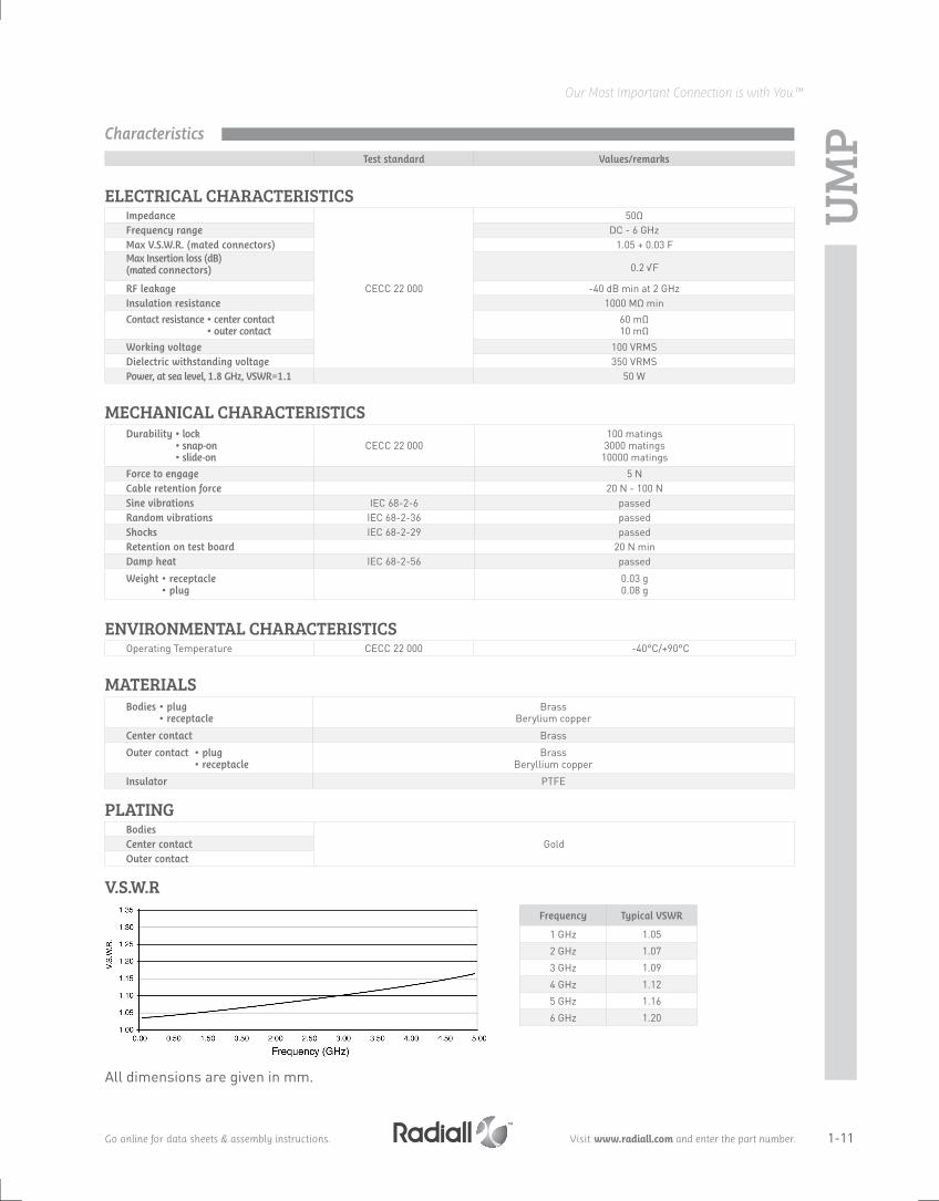
UMP
ELECTRICAL CHARACTERISTICS Impedance
CECC 22 000
50ΩFrequency range DC - 6 GHzMax V.s.W.r. (mated connectors) 1.05 + 0.03 FMax Insertion loss (dB) (mated connectors) 0.2 √F
rF leakage -40 dB min at 2 GHzInsulation resistance 1000 MΩ min Contact resistance • center contact
• outer contact60 mΩ10 mΩ
Working voltage 100 VRMS Dielectric withstanding voltage 350 VRMS Power, at sea level, 1 . 8 gHz, VsWr=1 . 1 50 W
MECHANICAL CHARACTERISTICSDurability • lock
• snap-on • slide-on
CECC 22 000100 matings
3000 matings10000 matings
Force to engage 5 nCable retention force 20 n - 100 n sine vibrations IEC 68-2-6 passedrandom vibrations IEC 68-2-36 passedshocks IEC 68-2-29 passedretention on test board 20 n minDamp heat IEC 68-2-56 passed
Weight • receptacle • plug
0.03 g0.08 g
ENVIRONMENTAL CHARACTERISTICS Operating Temperature CECC 22 000 -40°C/+90°C
MATERIALSBodies • plug
• receptacle Brass
Berylium copper
Center contact Brass
Outer contact • plug • receptacle
Brass Beryllium copper
Insulator PTFE
PLATINGBodies
goldCenter contactOuter contact
V.S.W.R
Test standard Values/remarks
All dimensions are given in mm.
Frequency Typical VsWr
1 GHz 1.05
2 GHz 1.07
3 GHz 1.09
4 GHz 1.12
5 GHz 1.16
6 GHz 1.20
Characteristics

1-12
Our Most Important Connection is with You.™
Go online for data sheets & assembly instructions. Visit www.radiall.com and enter the part number.
SMT RECEPTACLES
PIGTAILS
BETWEEN SERIES CABLE ASSEMBLIES
Fig. 1
Fig. 1
Fig. 2
Fig. 2
UMP type Part numberDimensions (mm)
Finish Packaging reel dimensions (mm)
Assembly instructionsA B C
H2 R107 003 010 3.6 2 2.05
gold
100 pieces 180
M02H2.6R107 103 030
5 2.6 2.453300 pieces 330
R107 103 040 100 pieces 180
H3 R107 303 040 5.5 3 2.95 100 pieces 180
Cable Cable group UMP type Mating type Part number FigDimensions (mm)
PackagingA B
C291 050 066 1/50/S H2lock R285 020 202 1 1.74
4 100 pieces
snap-on R285 020 212 2 1.65
C291 140 087 2/50/SH2.6
lock R285 020 301 1
2.34snap-on R285 020 311 2
C291 180 072 2/75/S lock R285 020 302 1
C291 170 017 2.6/50/S H3 lock R285 020 401 1 2.84
Cable Cable group UMP type Mating type Part number Fig series Packaging
C291 050 066 1/50/S H2lock R285 025 202 1
UMP/SMA 20 pieces
snap-on R285 025 212 2
C291 140 087 2/50/S H2.6lock R285 025 301 1
snap-on R285 025 311 2
C291 170 017 2.6/50/S H3 lock R285 025 401 1
UMP
Snap-on
Snap-on
Lock
Lock
Receptacles,pigtails and cable assemblies

1-13
Our Most Important Connection is with You.™
Go online for data sheets & assembly instructions. Visit www.radiall.com and enter the part number.
PROdUCTION LINE TEST AdAPTER: UMP - SMA FEMALE (to be used with lock and snap pigtails only)
EXTRACTION TOOL (for lock version only)
INSERTION TOOL (optional)
Part number Connector height (mm) Packaging
R107 009 901 H 2
UnitR107 009 902 H 2.6
R107 009 903 H 3
Part number Photo note To disconnect Packaging
R282 867 020 1 axial disconnection H 210 pieces
R282 867 030 2 lateral disconnection H 2.6 and H 3
Part number
R282 203 020
Photo 1 Photo 2
UMP
For measurement and test purposes. Packaging: unit.
The 2 disconnection tools allows axial and lateral disconnec-tions depending on the occupied space on the PCB. Please see extraction procedure on page 1-16.
This optional tool allows you a more precise connection in a limited space.Please see manual connection on page 1-16.
Packaging: Unit.
Tools and accessories

1-14
Our Most Important Connection is with You.™
Go online for data sheets & assembly instructions. Visit www.radiall.com and enter the part number.
UMP
ACCORDINg TO IEC 286-3 STANDARDMATERIALS Reel: polyester Carrier tape: antistatic PETg (polyester) Cover tape: polyester
H2 type receptacle
H3 type receptacle
H2.6 type receptacle
PRECAUTION fOR USEAutomated pick and place machines use standard tooling to peel the antistatic film off. Sometimes the "A" dimension of this tool is shorter than the overall "B" width between the two legs of the receptacle. There is thus a risk for the two legs being deformed while they pass through the tool during the suction operation. The user must then widen the "A" dimension of the peeling tool.
RECEPTACLE SOLDERIng PATTERnS FOR COPLAnAR LInE
Part number
R107 003 010
Part number
R107 303 040
Part number
R107 103 030R107 103 040
M02
gold over nickel prefered for solder pastegold can be replaced by tin lead (see test report SC2000.02.6587)
gold over nickel contact area free of any surface contaminant
ground + varnish
PCB thickness (mm)
Coplanar ligne A (mm)
0.8 0.183
1.0 0.190
1.2 0.195
1.6 0.20
Receptacle packaging
Assembly instructions

1-15
Our Most Important Connection is with You.™
Go online for data sheets & assembly instructions. Visit www.radiall.com and enter the part number.
H2 type receptacle H3 type receptacleH2.6 type receptaclePart number
R107 003 010
Part number
R107 303 040
Part number
R107 103 030R107 103 040
IMP
VIDEo SHADoWS
SUCTIOn PROCEDURE
OTM Cover
M02 (Flg)Assembly instructions

1-16
Our Most Important Connection is with You.™
Go online for data sheets & assembly instructions. Visit www.radiall.com and enter the part number.
UMP Manual connection
Axial disconnectionTool R282 867 020 (see page 1-13).
Lateral disconnectionTool R282 867 030 (see page 1-13).
Extraction tool only needed to disconnectlock couplingmechanism.
Disconnectingtool must be
against the body
Connection and extraction
Do not push over the "clic"
CLIC