Embed Size (px)
Citation preview

1
Secure Satellite Communication Systems
Design with Individual Secrecy Rate
ConstraintsJiang Lei†, Zhu Han‡, M. A. Vazquez-Castro†, and Are Hjørungnes∗
†Dept. Telecom. and Systems Engineering Universitat Autonoma de Barcelona, Spain‡Electrical & Computer Engineering Department, Universityof Houston, USA
∗UNIK - University Graduate Center, University of Oslo, Norway
Abstract
In this paper, we study multibeam satellite secure communication through physical (PHY) layer secu-
rity techniques, i.e., joint power control and beamforming. By first assuming that the Channel State Infor-
mation (CSI) is available and the beamforming weights are fixed, a novel secure satellite system design is
investigated to minimize the transmit power with individual secrecy rate constraints. An iterative algorithm
is proposed to obtain an optimized power allocation strategy. Moreover, sub-optimal beamforming weights
are obtained by completely eliminating the co-channel interference and nulling the eavesdroppers’ signal
simultaneously. In order to obtain jointly optimized powerallocation and beamforming strategy in some
practical cases, e.g., with certain estimation errors of the CSI, we further evaluate the impact of the
eavesdropper’s CSI on the secure multibeam satellite system design. The convergence of the iterative
algorithm is proven under justifiable assumptions. The performance is evaluated by taking into account
the impact of the number of antenna elements, number of beams, individual secrecy rate requirement,
and CSI. The proposed novel secure multibeam satellite system design can achieve optimized power
allocation to ensure the minimum individual secrecy rate requirement. The results show that the joint
beamforming scheme is more favorable than fixed beamformingscheme, especially in the cases of a
larger number of satellite antenna elements and higher secrecy rate requirement. Finally, we compare the
results under the current satellite air-interface in DVB-S2 and the results under Gaussian inputs.
Index Terms
Multibeam satellite, beamforming, physical layer security, and power allocation.

2
I. INTRODUCTION
The issues of privacy and security in satellite networks have taken on an increasing important role,
especially in military applications. Currently, the secure satellite communication (SATCOM) is realized
only through upper layer protocols (e.g., in [1], [2]). In this paper, we will investigate the multibeam
satellite secure communication through physical (PHY) layer security techniques [3], [4], i.e., joint
power control and beamforming schemes with individual secrecy rate constraints, which can be an
alternative approach for satellite secure communication.Power limitation and co-channel interference are
two challenges for multibeam satellite systems (e.g., in [5]–[8]). Hence, power control and beamforming
could be two approaches for improving the system capacity byadjusting the beam pattern such that
the overall transmitted power is minimized or the Signal-to-Interference plus Noise Ratio (SINR) is
maximized.
In this paper, we consider the joint power and beamforming with individual secrecy rate constraints.
An iterative algorithm is proposed for updating the transmission power in each iteration, such that a
target secrecy rates are achieved for each beam with minimalpower consumption. We first study the
secure SATCOM system design through a power control problemwith fixed beamforming. Next, the
beamforming weights are achieved by co-channel interference cancelation and nulling the signal at
the eavesdropper. Moreover, the impact of Channel State Information (CSI) of eavesdropper on secure
SATCOM system design is studied.
In addition to security issues, the efficient resources management is also important for the SATCOM
systems, e.g., bandwidth and power allocation. The authorsn [9], [10] investigate the dynamic bandwidth
allocation techniques for satellite systems. For the powercontrol techniques in the satellite scenario, a
power allocation policy is proposed in [5], which suggests to stabilize the system based on the amount
of packets in the queue and the channel state, and a routing decision is made for the maximum total
throughput. In [11], a tradeoff strategy is proposed between different objectives and system optimization.
However, the co-channel interference is not taken into account and a convex optimization problem
is solved. A joint power and carrier allocation problem is discussed in [6], however, only uplink is
considered. In [7], [8], the authors focus on the capacity optimization in multibeam satellite system, and
the duality of in frequency and time domain is studied. The optimization problem of power and carrier
allocation has been addressed in terrestrial networks (e.g. [12], [13]). The authors in [13] propose an
axiomatic-based interference model for SINR balancing problem with individual target SINR per user,
but the conclusions are not directly extrapolable to a satellite scenario. To the best of our knowledge,

3
the security issue is not discussed together with power control and beamforming in SATCOM systems.
Beamforming is a sub-optimal strategy to reduce co-channelinterference, but it has reduced complexity
compared to Dirty-Paper Coding (DPC). In [14] and [15], transmit beamforming has been used to null the
signal for each co-channel receiver. In [16], the authors studied the Zero-Forcing Beam-Forming (ZFBF) in
the scenario of multiantenna broadcast where the weights are selected such as the multi-user co-channel
interference is cancelled (zero-interference condition). Our work is different from the aforementioned
literatures, since we introduce the physical (PHY) layer security for multibeam satellite systems and
focus on the power control and co-channel interference managementjointly.
Previous work (in [5]–[8], [11]–[15]) addresses the problems of power control by SINR balancing and
beamforming separately, and without taking into account the secure communication issues. For security
in SATCOM networks, there exits various works ( [1], [2]). However, most of it only focus on the upper
layer security and realize through protocols, e.g., Authentication, Authorization, and Accounting Proto-
cols (AAA), Transport Layer Security protocol (TLS), IP Security (IPSEC), Point-to-Point Tunnelling Pro-
tocol (PPTP), Internet Keying Exchange (IKE), and InternetSecurity Association and Key Manage-
ment Protocol (ISAKMP) (in [2]). The PHY layer based security of wireless communication has been
investigated since the contributions in [3], [4]. Recently, the application of PHY layer security in wireless
communication is attracting more attention. E.g., in [17]–[19], the relay cooperating schemes are studied
in order to maximize the achievable secrecy rate or minimizethe transmit power. All the relays forward
a weighted version of the decoded/amplified signal to the destination, thus, a maximized secrecy rate or
minimized transmit power can be achieved by optimizing the weighting factor of each relay. The authors
in [20] generalize the secure communication over the fadingchannels, the power allocation is derived
to minimize the outage probability. Some recent work (in [21]–[28]) has been proposed to improve the
performance, e.g., achievable secrecy rate, by taking advantage of multiple antenna systems. The authors
in [21]–[25] investigate the PHY layer security by using Multiple-Input Multiple-Output (MIMO) systems.
In [26], [27], the authors study the achievable rates in Gaussian Multiple-Input Single-Output (MISO)
channels with secrecy constraints and conclude that the optimal solution can be achieved by beamforming
in terms of the input covariance matrices. The Single-InputMultiple-Output (SIMO) case is studied
in [28].
The main contributions of this paper are:
• We apply the PHY layer security in SATCOM scenarios, which isnovel in the satellite networks.
Since currently the security SATCOM is realized through upper layer protocols.
• We model the system as a MISO wiretap channel, which is different from the aforementioned

4
papers in various aspects. Existing MIMO/MISO models focuson the antenna-level for the terrestrial
networks, while we focus on the beam-level for multibeam SATCOM systems. It means that, for a
specific ground terminal, it corresponds to a specific beam onthe satellite, the received signals by
this terminal from other beams are considered as co-channelinterference.
• The nature of the studied problem is different from the previous works. Existing works focused on
the analysis of the achievable secrecy rate. Our aim is to characterize the secure SATCOM system
through PHY layer design, i.e., power allocation and beamforming design under the individual
secrecy rate constraints.
The main results of this paper can be summarized as:
• We prove that the proposed novel multibeam SATCOM system design can achieve the secure
communication by jointly optimizing the power allocation and beamforming. As expected, in order
to achieve the target secrecy rate, more power will be consumed in the cases of worse legitimate
users’ CSI and better eavesdropper’s CSI.
• Two schemes, power control with fixed beamforming and with joint beamforming, are investigated
and compared. We show that the joint beamforming scheme is more favorable than the fixed
beamforming scheme, especially in the cases of a larger number of antenna elements and higher
individual secrecy rate constraints.
• By comparing the results under the Gaussian inputs with the results under the current air-interface
in DVB-S2, we come to the same conclusions.
The rest of this paper is organized as follows: In Section II,we model the multibeam downlink system
to obtain a mathematical expression of the secrecy SINR and secrecy rate. The power control problem
with fixed beamforming and iterative algorithm are studied in Section III. In Section IV, we propose and
solve a joint power control and beamforming problem. The beamforming weight vector for each beam is
obtained by joint ZFBF and eavesdropper nulling. The impactof the eavesdropper’s CSI on the system
design is presented in Section V. The performance of the algorithm and numerical results are presented
in Section VI. In Section VII, we draw the conclusions.
We adopt the following notation: Bold uppercase letters denote matrices and bold lowercase letters
denote vectors,(·)∗, (·)T and (·)H denote conjugate, transpose, and conjugate transpose, respectively,
(·)† denotes the Moore Penrose inverse,E{·} denotes the expectation, var{x} denotes the variance ofx,
diag{x} denotes a diagonal matrix with the elements of vectorx along its main diagonal,0M×N denotes
an all-zero matrix of sizeM × N , ‖x‖ denotes the Euclidean norm of the vectorx, IM is the identity
5
matrix of sizeM × M , [X]ij denotes the(i, j) entry of the matrixX, [x]j denotes thejth entry of the
vectorx, and log(·) denotes the base-2 logarithm.
II. SYSTEM MODEL
In the multibeam SATCOM system, we assume a security scenario (e.g., military application, as shown
in Fig. 1), where only a few beams (K) are illuminated by coherently processing (e.g., beamforming) M
antenna elements. TheK illuminated beams serveK decentralized legitimate users in the same frequency
band. One eavesdropper, denotede, is located outside/inside the satellite coverage. Both legitimate users
and eavesdropper are assumed equipped with a single antenna. Therefore, for each of the specific user,
the system can be seen as a MISO wiretap channel. It is different from the MISO model in [26], [27],
because we focus on the beam-level and co-channel interference is taken into account. Our aim is to
realize secure communication between the satellite and thelegitimate users by transmit power control
and beamforming. Next, we introduce the different sub-models.
A. Channel Attenuation Amplitude Model
The attenuation due to the atmosphere depends on the frequency, the elevation angle, the altitude of
the station, and the water vapor concentration [29]–[32]. As discussed in [33], the atmosphere attenuation
(e.g., rain attenuation) is negligible at lower frequencies, e.g., less than 10 GHz, but has a strong impact
on the performance at higher frequencies, e.g., Ka-band andabove frequencies, which is the frequency
band applied in current SATCOM systems [6]–[8]. Attenuation also depends on the distance that the
electromagnetic wave propagates through space, i.e., pathloss. We assume an instantaneous analysis
with fixed channel transfer coefficients. The channel attenuation amplitude matrixA ∈ CK×K is defined
as
A = diag{α1, α2, . . . , αK} , (1)
whereαi denotes the channel attenuation factor for legitimate useri where i = 1, 2, . . . ,K. The channel
attenuation factor for the eavesdropper is defined asαe.
B. Antenna Model
We assume an Array Feed Reflector (AFR) antenna system [7], [8], [11], which is able to exploit the
spatial characteristics of the propagation channel. Each beam is synthesized by adding array elements,
hence, we can provide flexible power allocation by controlling the On-Board Processor (OBP). The array
antenna system can achieve large performance gains, depending on the number of antenna elements
6
and their relative position in space. However, these gains come at the cost of the increased hardware
complexity. We suppose that the antenna gain matrixG of sizeM × K is given as
G =
g11 g12 . . . g1K
g21 g22 . . . g2K
......
. . ....
gM1 gM2 . . . gMK
,
where gij is the square root of the gain between theith beam on-board antenna element and the
jth legitimate user. The antenna gain betweenM antenna elements and the eavesdropper isge =
[g1e, g2e, . . . , gMe]T .
C. Overall Channel Model
Let H = GA be the overall channel matrix(M × K) for the legitimate users, and lethe = αege be
the overall channel gain vector(M × 1) betweenM antenna elements and the eavesdropper. The overall
channel between the satellite antenna elements and the legitimate users can be estimated accurately, e.g.,
by introducing a feedback channel. However, in practice, the channel condition between the satellite
antenna elements and the eavesdropper is difficult to be estimated or is even totally unknown. In [34],
the authors studied the possibility to estimate perfectly the CSI of the eavesdropper. However, it is only
applicable in networks combining multicast and unicast transmissions, in which the terminals play dual
roles as legitimate users for some signals and eavesdroppers for others.
In this paper, we do not focus on the CSI estimation, however,we study the system design of power
control and beamforming with given CSI knowledge. Specifically, the two cases of complete eavesdropper
CSI knowledge and imperfect eavesdropper CSI knowledge, are discussed. The first case is a common
assumption in the PHY security literatures [19]–[21]. The attenuation factor can be estimated for the
eavesdropper according to the method proposed in [29]–[32]. For the second case, which is more realistic
in practical, we assume that only imperfect estimates of theeavesdropper’s CSI are available.
D. Received Signal Model
Let sk be the transmitted data symbol to Userk. The amplitude of the signal transmitted to each user is
normalized to one, i.e,E{|sk|2} = 1, for k = 1, 2, . . . ,K. We denote byPk the allocated power to the
kth beam and, hence,p = [P1, P2, . . . , PK ]T is the power allocation vector to all the beams. All signals are
mapped onto the antenna array elements by the beamforming vectorswk ∈ CM×1, for k = 1, 2, . . . ,K.

7
Hence, the beamforming matrixW ∈ CM×K is given by W = [w1,w2, . . . ,wK ]. Without loss of
generality, we assume that‖wk‖ = 1, for k = 1, 2, . . . ,K. Under this assumption, the transmitted
power for each beam (e.g., beamk) is given byPkE{|sk|2} = Pk.
The block matrix model of the satellite broadcast scenario is shown in Fig. 2. The signals received by
the kth user can be expressed as desired signal and interference as
yk =√
PkhTk wksk +
∑
j 6=k
√Pjh
Tk wjsj + nk, (2)
wherehk (the kth column ofH) is the channel vector(M × 1) betweenM antenna elements and the
user in thekth ground cell.nk is signal-independent zero-mean complex circular Gaussian noise with
varianceσ2k at beamk.
The signal received by the eavesdropper is given as
ye =√
PkhTe wksk +
∑
j 6=k
√Pjh
Te wjsj + ne, (3)
where the term√
PkhTe wksk is the desired signal if the eavesdropper intend to wiretap the kth user.
hTe wj denotes the channel gain between the eavesdropper and thejth antenna element, andne is a
zero-mean complex circular Gaussian noise at the eavesdropper. We assume that the noise level at the
legitimate user (e.g., userk) is equal to that of at the eavesdropper, i.e., var{nk} = var{ne} = σ2,∀k .
This is a reasonable assumption since the sensitivity of allthe terminals is often similar.
E. Signal-to-Interference Plus Noise Ratio
Let Rk , (hkhHk )T , for k = 1, 2, . . . ,K, andRe , (heh
He )T . According to the formulation of the
received signal in (2) and (3), we can derive the SINR of the legitimate userk as
Γk =Pkw
Hk Rkwk
σ2 +∑
j 6=k
PjwHj Rkwj
, (4)
and the SINR of the eavesdropper, which intend to wiretap thesignal transmitted to userk as
Γek =Pkw
Hk Rewk
σ2 +∑
j 6=k
PjwHj Rewj
. (5)
F. Secrecy Rate Model
As we have indicated in the introduction, there have been several precedents that investigate the PHY
layer security of the MIMO wiretap channel, but they only focus on the terrestrial networks. Certainly,

8
these results also cover the special case of the MISO channel. For the case of one eavesdropper, an
achievable secrecy rate for a specific user (e.g., for thekth user) is given as [19, Eq. (10)]
Rks = max{Rk − Rek}, (6)
where the achievable of the maximum was shown in [25], [27] with Gaussian inputs,Rk is the achievable
rate of the link between the satellite and thekth user, andRek is the achievable rate of the link between
the satellite and the eavesdropper. Note that the secrecy rate in (6) is achievable unless the maximum
value is negative, in which case, the achieved secrecy rate is zero [4]. In this paper, we focus on the
practical scenario in which the secrecy rate is positive.
In [26], [27], the authors discuss how to maximize the difference by adaptively adjust the power
allocation. Conversely, we restrict ourselves to the difference betweenRk and Rek. Our aim is to
characterize the best power allocation scheme over multibeam SATCOM systems subject to the individual
secrecy rate constraints, i.e. the differenceRk − Rek for each user.
By assuming Gaussian inputs, the difference betweenRk andRek can be written as
Rk − Rek = log (1 + Γk) − log (1 + Γek) = log1 + Γk
1 + Γek= log
(1 +
Γk − Γek
1 + Γek
)= log
(1 + Γk
s
), (7)
whereΓks is defined as the secrecy SINR, which is the updated SINR afterintroducing the eavesdropping,
and it is given by
Γks ,
Γk − Γek
1 + Γek. (8)
From (4) and (5), we notice thatΓks is a function of two parameters, i.e., the beamforming matrix
W and the power vectorp. In the next sections, we will discuss how to minimize the overall power
consumption (sum of the elements insidep) under the SINR constraint per beam by taking into account
both fixed and optimized beamforming matrix. From (7), we cansee that the optimization problem with
a secrecy SINR constraint is equivalent to the secrecy rate constraint. If we consider that the secrecy rate
required by thekth user isRks , the secrecy SINR requirement can be derived asγk = 2Rk
s −1. Therefore,
in the following section, we focus on the power control problem with a secrecy SINR constraint per user.
III. POWER CONTROL PROBLEM WITH FIXED BEAMFORMING
In this section, we assume that the beamforming matrixW = [w1, w2, . . . , wK ] is optimized, with
‖wk‖ = 1, for k = 1, 2, . . . ,K. We focus on the secure SATCOM system design through power
allocation with individual SINR constraints.

9
A more general solution based on [35] is proposed to solve thepower control problem. By doing
the multibeam satellite power control, the overall transmit power of each beam is optimized, so that the
received secrecy rate of each user satisfiesRks ≥ Rk
s , for k = 1, 2, . . . ,K, i.e., the secrecy SINR has
Γks ≥ γk for k = 1, 2, . . . ,K, (whereγk is the predefined targeted SINR threshold in order to realizethe
required secrecy rate), while the overall transmitted power used by all beams is minimized. Hence, the
power control problem can be defined as
minp
∑
k
Pk, (9)
subject toΓks(W,p) ≥ γk, k = 1, 2, . . . ,K.
The minimum power is achieved when the SINR is equal to the target value, i.e.,Γks = γk for
k = 1, 2, . . . ,K. The problem in (9) is a Nondeterministic Polynomial (NP) hard problem [36, Chapter 5,
pp. 109]. Therefore, an iteration algorithm is proposed to find a solution. Many iteration algorithms (e.g.,
in [37]–[39]) have been proposed in order to decrease the complexity. However, the algorithm in this
paper is different, since the eavesdropper is present.
We first construct the complete iteration expression asI(pn), which is a power-update equation.pn =
[Pn1 , Pn
2 , . . . , PnK ]T is the power vector for all theK beams at thenth iteration step. Then, for each beam
(e.g., beamk), the interference functionIk(p) can be derived. The power allocated to each beam can be
iteratively updated until converge with the individual secrecy SINR constraints. The algorithm steps at
the (n + 1)th iteration are as follows:
Iteration Algorithm:
pn+1 = I(pn) (10)
The power-update for thekth beam at the(n + 1)th iteration is
Pn+1k =
γk
µnk − (1 + γk)µ
nek
, Ik(pn), (11)
whereµnk andµn
ek are defined as
µnk =
Γnk
Pnk
=Θkk
σ2 +∑
j 6=k
Pnj Θkj
, (12)
and
µnek =
Γnek
Pnk
=Θek
σ2 +∑
j 6=k
Pnj Θej
, (13)
10
respectively, whereΓnk andΓn
ek are the updated SINR of the legitimate userk and the eavesdropper at
the nth iteration step,Θkk = wHk Rkwk, Θkj = wH
j Rkwj, Θek = wHk Rewk, andΘej = wH
j Rewj.
The computation ofΘkk, Θkj, Θek, andΘej dominates the computational complexity of the algorithm.
Sincewk is a M × 1 vector,Rk andRe are M × M matrices, thus, the expressions in (12) and (13)
require a computational complexity ofO(M4) for updating the allocated power per user. Thus, the
computational complexity is quite high for the cases of large number of beams. However, in this paper,
we assume a security scenario (e.g., military application), where only a few beams are implemented,
hence, the number of antenna elementM is quite low (e.g., max. 20 as we assumed), and the proposed
algorithm computational complexity is reasonable. In addition, since the satellite channel is relatively
stable, the computations needed are less frequently. Moreover, as we have noted in the antenna model
section, although the array antenna system can achieve large performance gains with large number of
antenna elementsM , these gains come at the cost of the increased hardware complexity and computational
complexity.
In [35], [40], the authors have proved that if the interference function isstandard, the algorithm will
achieve the optimal solution if there exists at least one feasible solution. The interference functionIk(p)
is standard if for all p ≥ 0 the following three properties are satisfied [35], [40]:
• Positivity: Ik(p) > 0.
• Monotonicity: If p ≥ p′, thenIk(p) ≥ Ik(p′) or Ik(p) ≤ Ik(p
′).1
• Scalability: For allρ > 1, ρIk(p) > Ik(ρp).
For the proposed interference function (11), we obtain the following theorem:
Theorem 1: The interference functionIk(pn) in (11) is astandard function under the following three
conditions:
• Condition 1:bk > ck.
• Condition 2:bkhk > ckhe, bkhe > ckhk, andbkhkhTk > ckheh
Te , bkheh
Te > ckhkh
Tk , ∀k.2
• Condition 3:√
bk[hk]jhe >√
ck[he]jhk, ∀k, j 6= k.
Wherebk = Θkk, ck = (1 + γk)Θek, andhk denotes the channel gain vector(K × 1) of the interference
1The inequality between two vectors, e.g.,x ≥ y, means thatxi ≥ yi for i = 1, . . . , K, wherex = [x1, x2, . . . , xK ],
y = [y1, y2, . . . , yK ].
2The inequality between two matrices, e.g.,X ≥ Y, means that[X]ij > [Y]ij , ∀i, j.

11
contribution to the desired user, defined as
[hk]j =
Θkj, if j 6= k,
0, otherwise.
he denotes the channel gain vector(K × 1) of the interference contribution to the eavesdropper, defined
as
[he]j =
Θej, if j 6= k,
0, otherwise.
The proof Theorem 1 is presented in Appendix A.
In a practical scenario, the overall channel gain of the link“satellite - desired user” is much larger
than that of the link “satellite - co-channel users”, i.e.,Θkk ≫ Θkj for ∀j 6= k, the overall channel
gain of the link “satellite - desired user” is larger than that of the link “satellite - eavesdropper”, i.e.,
Θkk ≫ Θej for ∀j. The magnitudes ofΘkj and Θej are roughly equal. Therefore, with the lower
secrecy SINR requestγk, the above three conditions are indeed satisfied. In the caseof very high SINR
requirement, we can introduce optimization of the satellite antenna beamformer in order to decrease or
eliminate the co-channel interference and the eavesdropper interference, and thereby the above conditions
can still be satisfied.
IV. JOINT POWER CONTROL AND BEAMFORMING
The level of co-channel interference and wiretapped signalfor each user depend both on the gain
between interfering transmitters and user, as well as on thelevel of transmitter powers, i.e., the optimal
beamforming vector may vary for different power allocationpolicy. Hence, in this section, we first obtain
a sub-optimal beamforming weight vector by completely eliminating the co-channel interference and
nulling the eavesdroppers’ signal simultaneously. Then, the power solution can be optimized when the
secrecy rate is equal to the target value.
In the joint power control and beamforming problem, the objective is to find the optimal weight
matrix W and power allocation vectorp such that the secrecy SINR threshold is achieved by all the
users, while minimize the transmission power. The problem can be formulated as
minW,p
∑
k
Pk, (14)
subject toΓks(W,p) ≥ γk, k = 1, 2, . . . ,K.
12
This problem can be solved in two steps: Firstly, we obtain the beamforming weight matrixW by
joint ZFBF and eavesdropper signal nulling, in which all theco-channel signal and eavesdropper signal
are completely eliminated. Secondly, the optimized power allocation solution can be obtained by solving
Γks = γk for k = 1, 2, . . . ,K, under the beamforming weights obtained in the first step.
A. Joint Zero-Forcing Beamforming and Eavesdropper Nulling
In order to completely eliminate the co-channel interference and null the signals at the eavesdropper, we
assume thatM > K. Note that in the case ofM ≤ K, we cannot completely eliminate the interference
from the co-channel users and nulling the signals at the eavesdropper; appropriate system design for the
case ofM ≤ K is an interesting future research direction.
By ZFBF (in [41], [42]), the weights are selected such as the co-channel interference is canceled (zero-
interference condition), i.e., for the desired userk, hTk wj = 0 for j 6= k. Similarly, the eavesdropping
interference can also be completely nulled by beamforming (e.g., in [17]–[19]), i.e., for the desired user
k, hTe wk = 0 for k = 1, 2, . . . ,K.
Hence, the secrecy SINR can be reformulated from (8) as
Γks(W,p) =
PkwHk Rkwk
σ2=
Pk|hTk wk|2σ2
. (15)
Therefore, in order to minimize the transmitted powerPk, for k = 1, 2, . . . ,K, under the secrecy
SINR constraintsγk, we have to maximize the gain between the satellite antenna and thekth user, i.e.,
max |hTk wk|2, for k = 1, 2, . . . ,K. It means that we have to solveK maximize problems jointly. The
kth optimization problem can be formulated as
maxwk
|hTk wk|2, (16)
subject to
hTk wj = 0, for j 6= k,
hTe wk = 0,
wHk wk = 1.
Note that the overall optimization problem is composed ofK optimization problems as expressed in
(16) (for k = 1, 2, . . . ,K). In an equivalent way, we re-formulate theK jointly maximize problems asK
independent maximization problem, e.g., the problem to solve thekth beamforming weight vector can

13
be formulated as
maxwk
|hTk wk|2, (17)
subject to
HTekwk = 0K×1,
wHk wk = 1,
whereHek is defined as
[Hek]ij ,
[H]ij , if j 6= k,
[he]i, if j = k.
(18)
The solution of the beamforming problem in (17) is given by [19, Eq. (23)] as
wk =(IM − Fe)h
∗k
‖ (IM − Fe)h∗k‖
, for k = 1, 2, . . . ,K, (19)
where
Fe = (Hek)†Hek,
where(Hek)† = (Hek)
H(Hek(Hek)
H)−1
is the Moore Penrose inverse ofHek (in [43]).
As discussed in Section III, the minimum power is achieved when the SINR is equal to the target
value, i.e.,Γks = γk for k = 1, 2, . . . ,K. Therefore, we can obtain the solution from (15) as
Pk =γkσ
2
|hTk wk|2
, for k = 1, 2, . . . ,K, (20)
wherewk is the solution of the beamforming weight vector for thekth beam.
V. IMPACT ON CSI OF EAVESDROPPER
The channels between the satellite and the desired users canbe estimated accurately, since they are
legitimate channels. However, in practice, the channels between the satellite and the eavesdropper can
only be estimated, and the estimation contains errors. In the following two subsections, we will investigate
the system design with unknown or imperfect CSI of the eavesdropper.
A. Unknown Eavesdropper CSI
In this case, we assume that the entries ofhe are random variables, andRe = E
{(heh
He )T
}is known
a priori. Therefore, in order to minimize the power consumption subject to given target secrecy SINR,
we can use a sub-optimal way to cancel the co-channel interference, i.e., ZFBF.

14
We can formulate thekth beamforming weight vector optimization problem as
maxwk
|hTk wk|2, (21)
subject to
hTk wj = 0, for j 6= k,
wHk wk = 1.
This problem is similar to the problem formulated in (16), thus, we obtain the solution as
wk =(IM − F)h∗
k
‖ (IM − F)h∗k‖
, for k = 1, 2, . . . ,K, (22)
where
F = (Hk)†Hk,
where (Hk)† = (Hk)
H(Hk(Hk)
H)−1
, and Hk is the co-channel contribution matrixM × (K − 1)
defined as
Hk , [h1, . . . ,hk−1,hk+1, . . . ,hK ], (23)
wherehj (j 6= k) is the jth column of the channel matrixH.
After obtain the beamforming vector for each beam, the powerallocation solution can also be obtained
by the iteration algorithm in (11), i.e.,
Pn+1k =
γk
µnk − (1 + γk)µ
nek
, (24)
whereµnk andµn
ek are re-defined inTheorem 2.
Theorem 2: The interference function in (24) is astandard function under the condition:bk > ck,
wherebk = wHk Rkwk, ck = (1 + γk)w
Hk Rewk. µn
k andµnek are defined as
µnk =
wHk Rkwk
σ2, (25)
and
µnek =
wHk Rewk∑
j 6=k
Pnj wH
j Rewj + σ2, (26)
respectively.
See Appendix B for the proof of Theorem 2.

15
B. Imperfect Eavesdropper CSI
The perfect channel gainhe ∈ CM×1 between the satellite antenna elements and eavesdropper is
modeled as
he = he + ∆e, (27)
wherehe ∈ CM×1 is the imperfect eavesdropper channel estimation, and∆e ∈ C
M×1 corresponds to the
channel estimation error. We assume that the entries of∆e are random variables, which is independent
of he, andR∆e, E
{(∆e∆
He )T
}is known a priori. Thus,
Re = E
{(heh
He )T
}= Re + R∆e
, (28)
whereRe = (hehHe )T .
By joint ZFBF and nulling the eavesdropper’s signal, we obtain the beamforming vector, e.g., for the
kth beam, as expressed in function (19). However,Hek is replaced withHek, which is defined as
[Hek]ij =
[H]ij , if j 6= k,
[he]i, if j = k.
(29)
We can solve the power control problem with the iteration algorithm in function (24), thenµnek is
re-defined as
µnek =
wHk R∆e
wk∑
j 6=k
Pnj wH
j R∆ewj + σ2
. (30)
As expressed inTheorem 2, the interference function in (24) isstandard with µnk and µn
ek given in
(25) and (30), respectively.
VI. SIMULATION RESULTS ANALYSIS
In order to evaluate the performance of the proposed system designs, we perform Monte Carlo
simulations consisting of 1000 independent trials to obtain the average results. We define the SATCOM
system payload parameters the same as in [7] and assume that the noise powerσ2 is -10 dBm. For
simplicity, the secrecy SINR request for all the beams is assumed to be equal, i.e.,γk = γ0 for
k = 1, 2, . . . ,K. The channel for each link is modeled as a product of an attenuation factor and a random
phase. For example, the channel between the legitimate userk and the antenna elementm is defined
as hmk = αkejς , and the channel between the antenna elements and the eavesdropper ishem = αee
jς ,
whereς is a random phase uniformly distributed within[0, 2π), and it is independent ofm andk.

16
We first fix the number of antenna elements toM = 8, the number of beams toK = 5, the channel
attenuation factorαk = αe = 0.8 for k = 1, 2, . . . ,K to investigate the convergence of the iteration
algorithm. In Fig. 3, the curves show the total power consumption at each iteration step for different
target secrecy SINR. The results show that the algorithm converge. Notice from the figure that the black
curve with higher target SINR (γ0 = 8 dB) converges slower than that of the red curve with lower target
SINR (γ0 = 6 dB), since more power is needed to achieve higher SINR requirements.
Fig. 4 illustrates satellite transmit power versus the number of antenna elementsM . The fixed beam-
forming vector (e.g., for beamk) is assumed as‖wk‖ = 1. The curves show that the transmitted
power in the scheme of fixed beamforming is almost independent of the number of antenna elements,
and the transmitted power in the scheme of joint beamformingdecreases as the number of antenna
elements increases. From the optimization point of view, the satellite transmitted power can be saved by
increasing the number of antenna elements. However, from the satellite payload designers’ point of view,
the complexity and the weight of the satellite will increaseas the number of antenna elements increases.
Therefore, the optimal number of antenna elements should bebalanced by taking into account all these
views.
In Fig. 5, we evaluate the transmitted power according to different number of beams on the satellite.
We fix the number of antenna elements atM = 15 and increase the number of beamsK from 2 to 12.
All other parameters are the same in Fig. 4. As expected, the power consumption increases as the number
of beams and secrecy request increase for both schemes. Especially, the transmitted power increases very
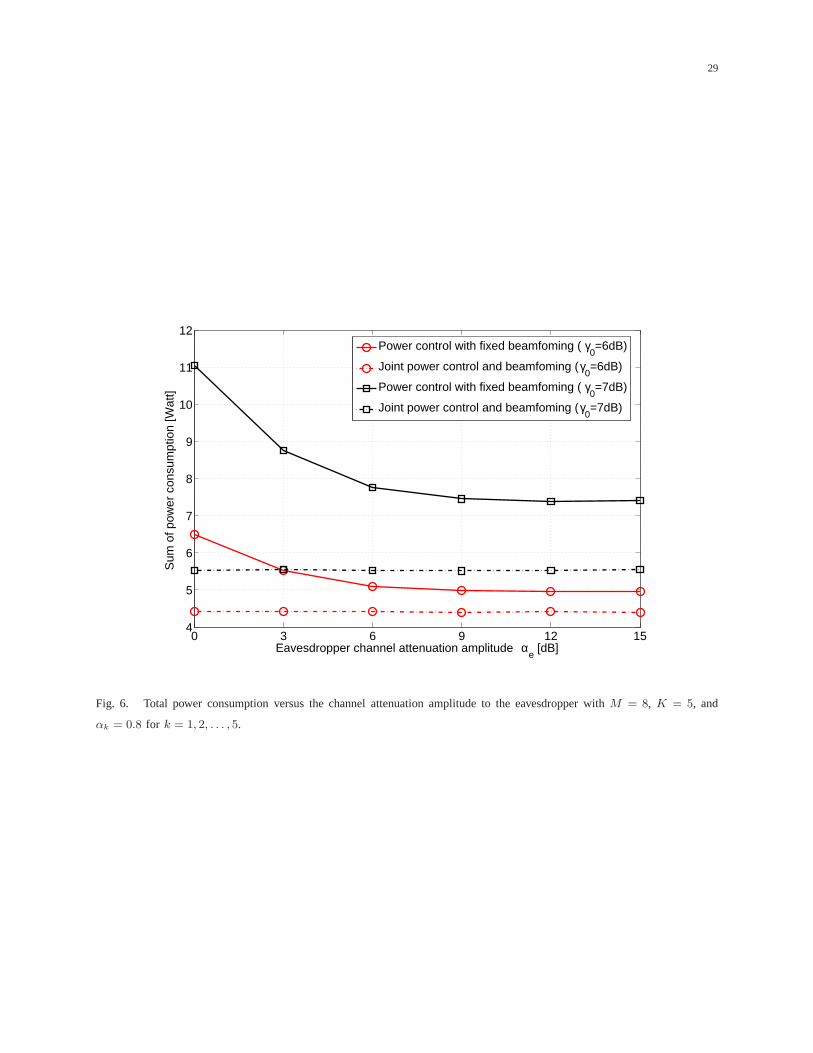
quickly in the case of a large number of beams. In Fig. 6, we simulate the power allocation according
to the channel attenuation amplitude of the eavesdropper, the horizontal axis in the figure indicates the
channel attenuation amplitude degradation in dB, e.g., 0 dBmeans the clear sky scenario. From the figure,
we see that the joint beamforming scheme is almost independent of the eavesdropper’s channel condition,
which means that the satellite can adapt the channel degradation by optimizing the beamformer design.
For the fixed beamforming scheme, the transmitted power willdecrease as the eavesdropper’s channel
condition deteriorates.
The performance of the transmit power as a function of the secrecy SINR request is shown in Fig. 7.
For simplicity, we assume that the channel attenuation amplitudes for all the users are the same, and the
channel attenuation amplitude of the eavesdropper is assumed asαe = 1, clear sky. All other parameters
are the same as previous figures. For both fixed beamforming and joint beamforming schemes, the
curves in Fig. 7 show that, as the channel condition deteriorates, more power will be consumed in order
to compensate the signal attenuation. We can also conclude from this figure that the joint beamforming

17
scheme is more favorable than fixed beamforming scheme in thecase of a higher secrecy SINR request,
since the power allocation is more sensitive to the higher secrecy SINR request (e.g., whenγ0 > 6 dB).
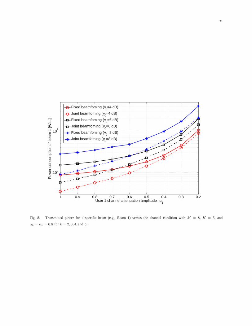
The performance of a single legitimate user (e.g., User 1) isevaluated in Fig. 8. We assume that the
channel attenuation amplitude of User 1 (α1) is changed from 1 (i.e., clear sky) to 0.2, and all other
parameters are the same in Fig. 3. As expected, the power allocated to Beam 1 will increase as the
channel condition of User 1 deteriorates, especially in thecase of a bad channel condition. In Fig. 9, we
compare the power allocation with and without the availableof the eavesdropper’s CSI. The value of the
parameters is the same in Fig. 7. Under the given total power limitation (e.g., 100 Watts), the achieved
secrecy SINR per user with known eavesdropper’s CSI performs about 2 dB better than the case of no
CSI available. In addition, this gap increases as the available total power increases.
In Fig. 10, we compare the results with Gaussian inputs and with the current air-interface in DVB-S2.
The value of the parameters is assumed to be the same as in Fig.7. For the case of the joint beamforming
scheme, the sum of power consumption increases as the spectral efficiency requirement increases for both
Gaussian inputs and DVB-S2 cases. The power consumption of the DVB-S2 case is always larger than
the Gaussian inputs case, and the gap between them tends to decrease as the spectral efficiency increases.
Table I shows the maximum number of users for different system designs. We assume thatPtot =
10Watt, γ0 = 6dB, andM = 20. The first row indicates the maximum capacity of the system design
for a fixed power allocation and a fixed beamforming system design, which is the baseline reference
system design. We can notice that the capacity of the system design only with the flexibility in power
allocation is around two times better than the reference one, and the capacity of the joint power control
and beamforming system design is five times better than the reference one. In addition, the table also
shows that the capacity of the joint power control and beamforming system design is not sensitive to the
eavesdropper’s channel condition.
VII. C ONCLUSIONS
By PHY layer techniques, we realize secure communication ofmultibeam SATCOM systems while
minimizing the overall transmitted power. The power control problems is developed in different cases
and an iterative algorithm is proposed to solve the problems. Specifically, we first assume that the
beamforming weights are fixed, and propose a novel secure SATCOM system design that minimizes the
satellite transmit power with individual secrecy rate constraints. A joint power control and beamforming
problem is investigated to realize secure communication. The beamforming weight vector is solved by
completely eliminating the co-channel interference and nulling the eavesdroppers’ signal simultaneously.

18
Furthermore, the impact of channel condition of eavesdropper on the secure system design is studied.
After the numerical simulation, we conclude that the proposed multibeam SATCOM system design can
realize the secure communication by joint power control andbeamforming. In order to achieve the target
individual secrecy rate per user, more power will be consumed in the cases of worse legitimate users’
CSI and better eavesdropper’s CSI. The results also show that the joint power and beamforming scheme
is more favorable than the fixed beamforming scheme in the cases of larger number of antenna elements
and higher secrecy SINR request. Under a given overall powerlimitation (e.g., 100 Watts), the maximum
secrecy SINR achieved per user with known eavesdropper’s CSI preforms 2 dB better than the case
without CSI available. By comparing the results with Gaussian inputs and with the current air-interface
in DVB-S2, we come to the same conclusions.
APPENDIX A
PROOF OFTHEOREM 1
A. Proof of Positivity
The interference functionIk(p) in (11) can be rewritten as
Ik(p) =ak
bk
σ2+pT hk
− ck
σ2+pT he
=ak
f(p), (31)
wherebk andck are defined in Section III, andak = γk > 0. f(p) is defined as
f(p) =bk
σ2 + pT hk
− ck
σ2 + pT he
=σ2 (bk − ck) +
(bkp
T he − ckpT hk
)
(σ2 + pT he
)(σ2 + pT hk
) . (32)
Under the assumed conditions, we obtainbk−ck > 0 andbkpT he−ckp
T hk > 0. Therefore,f(p) > 0,
and the positivity is proved.
B. Proof of Monotonicity
A preference operator orequivalent relation “⇔” is defined for indicating that two expressions are
equivalent. E.g., “Ik(p) monotonically increasing”⇔ “f(p) monotonically decreasing”, wheref(p) is
defined in (32).
Let ϕ(p) be defined asϕ(p) = ∂f(p)∂p
and, hence, “f(p) monotonically decreasing”⇔ “ϕ(p) <
0, if p > 0”. ϕ(p) can be formulated as
ϕ(p) =∂f(p)
∂p=
ckhe(σ2 + pT he
)2 − bkhk(σ2 + pT hk
)2 =ψ(p)
(σ2 + pT hk
)2(σ2 + pT he
)2 , (33)

19
where
ψ(p) = ckhe
(σ2 + pT hk
)2− bkhk
(σ2 + pT he
)2. (34)
Thus, “ϕ(p) < 0, if p > 0” ⇔ “ψ(p) < 0, if p > 0”. For the jth element ofψ(p), i.e.,ψj(p), it
can be presented as
ψj(p) = 2ck[he]j(σ2 + pT hk
)2− 2bk[hk]j
(σ2 + pT he
)2. (35)
Thus, in order to proveψ(p) < 0, it is equivalent to prove√
ck[he]j(σ2 + pT hk
)<
√bk[hk]j
(σ2 + pT he
). (36)
or,(√
ck[he]j −√
bk[hk]j
)σ2 + pT
(√ck[he]jhk −
√bk[hk]jhe
)< 0. (37)
Under the Conditions 2 and 3, we find that√
ck[he]j−√
bk[hk]j < 0 and√
ck[he]jhk−√
bk[hk]jhe <
0, respectively. Therefore, the inequality in (37) is satisfied and the monotonicity is shown.
C. Proof of Scalability
The scalability condition can be rewritten as (ifρ > 1)
ρak
bk
σ2+pT hk
− ck
σ2+pT he
>ρak
ρbk
σ2+ρpT hk
− ρck
σ2+ρpT he
, (38)
sinceIk(p) ≥ 0, the condition in (38) is equivalent to
bk
σ2 + pT hk
− ck
σ2 + pT he
<ρbk
σ2 + ρpT hk
− ρck
σ2 + ρpT he
. (39)
Inequality (39) is equivalent to
∆
(σ2 + pT hk)(σ2 + pT he)(σ2 + ρpT hk)(σ2 + ρpT he)< 0, (40)
where∆ is given by
∆ =σ6 (1 − ρ) (bk − ck) + σ4(1 − ρ2
) (bkp
T he − ckpT hk
)+ σ2ρ (1 − ρ)
[bk(p
T he)2 − ck(p
T hk)2],
(41)
where the condition in (40)⇔ “∆ < 0”. bk > ck is satisfied under the Condition 1, andbkpT he >
ckpT hk, and bk(p
T he)2 > ck(p
T hk)2 are satisfied under the Condition 2. Sinceρ > 1, ∆ in (41) is
proved that∆ < 0. Therefore, the scalability is also proved.

20
APPENDIX B
PROOF OFTHEOREM 2
As we proved in Appendix A, by replacinghk and he with hk = 0, and
[he]j =
wHj Rewj, if j 6= k,
0, otherwise,(42)
respectively, we will prove the positivity, monotonicity and scalability in the following.
A. Proof of Positivity
f(p) in (32) can be re-formulated as
f(p) =bk
σ2− ck
σ2 + pT he
=σ2 (bk − ck) + bkp
T he
σ2(σ2 + pT he
) . (43)
Sincebk ≥ ck, it follows that f(p) > 0, the positivity ofIk(p) is proved.
B. Proof of Monotonicity
ϕ(p) in (33) can be re-formulated withhk = 0 as
ϕ(p) =∂f(p)
∂p=
ckhe(σ2 + pT he
)2 > 0. (44)
Therefore,f(p) increase monotonically withp, the monotonicity ofIk(p) is proved.
C. Proof of Scalability
We can re-formulate∆ in (41) as (lethk = 0)
∆ =σ6 (1 − ρ) (bk − ck) + σ4(1 − ρ2
)bkp
T he + σ2ρ (1 − ρ) bk(pT he)
2. (45)
Sinceρ > 1 andbk > ck , ∆ in (45) is shown that∆ < 0. Therefore, the scalability is also proved.
ACKNOWLEDGMENT
This work is partially supported by US NSF CNS-0953377, CNS-0905556, CNS-0910461, ECCS-
1028782, and Research Council of Norway through projects 197565/V30, 183311/S10, and 176773/S10.

21
REFERENCES
[1] L. Liang, S. Iyengar, H. Cruickshank, and Z. Sun, “Security for flute over satellite networks,” inProc. Int. Conf. on
Commun. and Mobile Computing, Kunming, China, Jan. 2009, pp. 485–491.
[2] M. S. B. Mahmoud, N. Larrieu, and A. Pirovano, “An aeronautical data link security overview,” inProc. IEEE/AIAA Digital
Avionics Systems Conf., Orlando, USA, Oct. 2009, pp. 4.A.4–1 – 4.A.4–14.
[3] A. D. Wyner, “The wire-tap channel,”Bell Syst. Tech. Journal, vol. 54, no. 8, pp. 1355–1387, Oct. 1975.
[4] I. Csiszar and J. Korner, “Broadcast channels with confidential messages,”IEEE Trans. Inf. Theory, vol. 24, no. 3, pp.
339–348, May 1978.
[5] M. J. Neely, E. Modiano, and C. E. Rohrs, “Power allocation and routing in multibeam satellites with time-varying
channels,”IEEE/ACM Trans. Netw., vol. 11, no. 1, pp. 138–152, Feb. 2003.
[6] J. E. Barcelo, M. A. Vazquez-Castro, J. Lei, and A. Hjøungnes, “Distributed power and carrier allocation in multibeam
satellite uplink with individual sinr constraints,” inProc. IEEE Global Commun. Conf., Honolulu, USA, Nov.-Dec. 2009,
pp. 1–6.
[7] J. Lei and M. A. Vazquez-Castro, “Joint power and carrier allocation for the multibeam satellite downlink with individual
sinr constraints,” inProc. IEEE Int. Conf. on Commun., Cape Town, South Africa, May 2010, pp. 1–5.
[8] ——, “Frequency and time-space duality study for multibeam satellite communications,” inProc. IEEE Int. Conf. on
Commun., Cape Town, South Africa, May 2010, pp. 1–5.
[9] F. Chiti, R. Fantacci, and F. Marangoni, “Advanced dynamic resource allocation schemes for satellite systems,” inProc.
IEEE Int. Conf. on Commun., Seoul, Korea, May 2005, pp. 1–4.
[10] T. Pecorella, R. Fantacci, C. Lasagni, L. Rosati, and P.Todorova, “Study and implementation of switching and beam-
hopping techniques in satellites with on board processing,” in Proc. Int. Workshop on Satellite and Space Commun.,
Salzburg, Austria, Sep. 2007, pp. 206–210.
[11] J. P. Choi and V. W. S. Chan, “Optimum power and beam allocation based on traffic demands and channel conditions over
satellite downlinks,”IEEE Trans. on Wireless Commun., vol. 4, no. 6, pp. 2983–2993, Nov. 2005.
[12] M. Schubert and H. Boche, “Solution of the multiuser downlink beamforming problem with individual sinr constraints,”
IEEE Trans. Veh. Technol., vol. 53, no. 1, pp. 18–28, Jan. 2004.
[13] ——, “Qos-based resource allocation and transceiver optimization,” Foundations and Trends in Commun. and Inform.
Theory, vol. 2, no. 6, pp. 383–529, Aug. 2005.
[14] D. Gerlach and A. Paulraj, “Adaptive transmitting antenna array with feedback,”IEEE Signal Process. Lett., vol. 1, no. 10,
pp. 150–152, Oct. 1994.
[15] H. Liu and G. Xu, “Multiuser blind channel estimation and spatial channel pre-equalization,” inProc. IEEE Int. Conf.
Acoust., Speech, Signal Process., Detroit, MI, USA, May 1995, pp. 1756–1759.
[16] T. Yoo and A. Goldsmith, “On the optimality of multi-antenna broadcast scheduling using zero forcing beam forming,”
IEEE J. Sel. Areas Commun., vol. 24, no. 3, pp. 528–541, Mar. 2006.
[17] L. Dong, Z. Han, A. Petropulu, and H. V. Poor, “Secure wireless communications via cooperation,” inProc. of the 46th
Annu. Allerton Conf. Commun., Control, Computing, Monticello, IL, USA, Sep.-Oct. 2008, pp. 1132–1138.
[18] ——, “Amplify-and-forward based cooperation for secure wireless communications,” inProc. IEEE Int. Conf. Acoust.,
Speech, Signal Process., Taipei, China, Apr. 2009, pp. 2613–2616.
[19] ——, “Improving wireless physical layer security via cooperating relays,”IEEE Trans. Signal Process., vol. 58, no. 3, pp.
1875–1888, Mar. 2010.

22
[20] Y. Liang, H. V. Poor, and S. S. (Shitz), “Secure communication over fading channels,”IEEE Trans. Inf. Theory, vol. 54,
no. 6, pp. 2470–2492, Jun. 2008.
[21] E. Ekrem and S. Ulukus, “Gaussian mimo multi-receiver wiretap channel,” inProc. IEEE Global Commun. Conf., Honolulu,
USA, Nov.-Dec. 2009, pp. 1–6.
[22] S. Shafiee, N. Liu, and S. Ulukus, “Secrecy capacity of the 2-2-1 gaussian mimo wire-tap channel,” inProc. 3rd International
Symposium on Commun., Control and Signal Process., St. Julians, Malta, Mar. 2008, pp. 207–212.
[23] Z. Li, W. Trappe, and R. Yates, “Secret communication via multi-antenna transmission,” inProc. 41st Conf. Information
Sciences Systems, Baltimore, MD, USA, Mar. 2007, pp. 905–910.
[24] F. Oggier and B. Hassibi, “The secrecy capacity of the mimo wiretap channel,” inProc. IEEE Int. Symp. Inf. Theory,
Toronto, Ontario, Canada, Jul. 2008, pp. 524–528.
[25] T. Liu and S. Shamai, “A note on the secrecy capacity of the multiple-antenna wiretap channel,”IEEE Trans. Inf. Theory,
vol. 55, no. 6, pp. 2547–2553, Jun. 2009.
[26] A. Khisti and G. W. Wornell, “Secure transmission with multiple antennas i: The misome wiretap channel,”IEEE Trans.
Inf. Theory, vol. 56, no. 7, pp. 3088–3104, Jul. 2010.
[27] S. Shafiee and S. Ulukus, “Achievable rates in gaussian miso channels with secrecy constraints,” inProc. IEEE Int. Symp.
Inf. Theory, Nice, France, Jun. 2007, pp. 2466–2470.
[28] P. Parada and R. Blahut, “Secrecy capacity of simo and slow fading channels,” inProc. IEEE Int. Symp. Inf. Theory,
Adelaide, Australia, Sep. 2005, pp. 2152–2155.
[29] “Propagation data and prediction methods required forthe design of earth-space telecommunication systems,” ITU-R, Tech.
Rep. P.618-8, Apr. 2003.
[30] “Characteristics of precipitation for propagation modelling,” ITU-R, Tech. Rep. P.837-4, Apr. 2003.
[31] “Specific attenuation model for rain for use in prediction methods,” ITU-R, Tech. Rep. P.838-2, Apr. 2003.
[32] “Rain height model for prediction methods,” ITU-R, Tech. Rep. P.839-3, Feb. 2001.
[33] G. Maral and M. Bousquet,Satellite Communications Systems: Systems, Techniques and Technology, 5th ed. New York,
USA,: Wiley, 2009.
[34] M. Bolch, J. O. Barros, M. R. D. Rodrigues, and S. W. McLaughlin, “Wireless information-theoretic security,”IEEE Trans.
Inf. Theory, vol. 54, no. 6, pp. 2515–2534, Jun. 2008.
[35] R. Yates, “A framework for uplink power control in cellular radio systems,”IEEE Trans. Inf. Theory, vol. 13, no. 7, pp.
1341–1348, Sep. 1995.
[36] M. R. Garey and D. S. Johnson,Computers and Intractability: A Guide to the Theory of NP-Completeness, 5th ed. New
York, USA,: W. H. Freeman, 1979.
[37] F. Rashid-Farrokhi, L. Tassiulas, and K. J. R. Liu, “Joint optimal power control and beamforming in wireless network
using antenna arrays,”IEEE Trans. Commun., vol. 46, no. 10, pp. 1313–1323, Oct. 1998.
[38] F. Rashid-Farrokhi, K. J. R. Liu, and L. Tassiulas, “Transmit beamforming and power control for cellular wireless systems,”
IEEE J. Select. Areas Commun., vol. 16, no. 8, pp. 1437–1449, Oct. 1998.
[39] Z. Han and K. J. R. Liu, “Joint link quality and power management with fairness constraint over wireless networks,”IEEE
Trans. Veh. Technol., vol. 53, no. 4, pp. 1138–1148, Jul. 2004.
[40] Z. Han, N. Marina, M. Debbah, and A. Hjørungnes, “Physical layer security game: Interaction between source, eavesdropper
and friendly jammer,”EURASIP Journal on Wireless Communications and Networking, special issue on Wireless Physical
Layer Security, Jun. 2009, doi:10.1155/2009/452907.

23
[41] Q. Spencer, A. Swindlehurst, and M. Haardt, “Zero-forcing methods for downlink spatial multiplexing in multiusermimo
channels,”IEEE Trans. Signal Process., vol. 52, no. 2, pp. 461–471, Feb. 2004.
[42] O. Somekh, O. Simeone, Y. Bar-Ness, A. M. Haimovich, andS. S. (Shitz), “Cooperative multicell zero-forcing beamforming
in cellular downlink channels,”IEEE Trans. Inf. Theory, vol. 55, no. 7, pp. 3206–3219, Jul. 2009.
[43] S. L. Campbell and C. D. Meyer,Generalized Inverses of Linear Transformations. New York, USA,: Dover, 1991.

24
Satellite Earth Station Q
Satellite Earth Station 2
Satellite Earth Station 1
Content
Multibeam Satellite
1
2
3
Ke
1 2 M
Fig. 1. Multibeam SATCOM scenario.

25
W1
s1
s2
sK
G A
ny1
y2
yK
cross-talk from
multibeam antenna
path losses
rain attenuation
W2
WK
ye
Fig. 2. Block matrix model of the satellite broadcast channel.

26
1 5 9 13 17 21 250
5
10
15
20
25
30
Number of iterations n
Sum
of p
ower
con
sum
ptio
n [W
att]
γ0=6dB
γ0=7dB
γ0=8dB
Fig. 3. Total transmitted power versus the iteration numberwith M = 8, K = 5, andαk = αe = 0.8 for k = 1, 2, . . . , 5.

27
6 8 10 12 14 16 18 202
4
6
8
10
12
14
16
Number of antenna elements M
Sum
of p
ower
con
sum
ptio
n [W
att]
Power control with fixed beamfoming ( γ0=6dB)
Joint power control and beamfoming (γ0=6dB)
Power control with fixed beamfoming ( γ0=7dB)
Joint power control and beamfoming (γ0=7dB)
Fig. 4. Total transmitted power versus the number of antennaelements withK = 5 andαk = αe = 0.8 for k = 1, 2, . . . , 5.

28
2 3 4 5 6 7 8 9 10 11 12
101
Number of beams K
Sum
of p
ower
con
sum
ptio
n [W
att]
Power control with fixed beamfoming ( γ0=6dB)
Joint power control and beamfoming (γ0=6dB)
Power control with fixed beamfoming ( γ0=7dB)
Joint power control and beamfoming (γ0=7dB)
Fig. 5. Total transmitted power versus the number of beams with M = 15 andαk = αe = 0.8 for k = 1, 2, . . . , K.
29
0 3 6 9 12 154
5
6
7
8
9
10
11
12
Eavesdropper channel attenuation amplitude αe [dB]
Sum
of p
ower
con
sum
ptio
n [W
att]
Power control with fixed beamfoming ( γ0=6dB)
Joint power control and beamfoming (γ0=6dB)
Power control with fixed beamfoming ( γ0=7dB)
Joint power control and beamfoming (γ0=7dB)
Fig. 6. Total power consumption versus the channel attenuation amplitude to the eavesdropper withM = 8, K = 5, and
αk = 0.8 for k = 1, 2, . . . , 5.

30
−6 −4 −2 0 2 4 6 8 1010
−1
100
101
102
103
Secrecy SINR requested (γ0) [dB]
Sum
of p
ower
con
sum
ptio
n [W
att]
Fixed beamfoming (αk=1; clear sky)
Joint beamfoming (αk=1; clear sky)
Fixed beamfoming (αk=0.5)
Joint beamfoming (αk=0.5)
Fixed beamfoming (αk=0.25)
Joint beamfoming (αk=0.25)
Fig. 7. Total transmitted power versus the target secrecy SINR with M = 8, K = 5, andαe = 1.
31
0.20.30.40.50.60.70.80.91
100
101
User 1 channel attenuation amplitude α1
Pow
er c
onsu
mpt
ion
of b
eam
1 [W
att]
Fixed beamfoming (γ0=4 dB)
Joint beamfoming (γ0=4 dB)
Fixed beamfoming (γ0=6 dB)
Joint beamfoming (γ0=6 dB)
Fixed beamfoming (γ0=8 dB)
Joint beamfoming (γ0=8 dB)
Fig. 8. Transmitted power for a specific beam (e.g., Beam 1) versus the channel condition withM = 8, K = 5, and
αk = αe = 0.8 for k = 2, 3, 4, and5.

32
−6 −4 −2 0 2 4 6 8 10 12 14
100
101
102
Secrecy SINR requested γ0 [dB]
Sum
of p
ower
con
sum
ptio
n [W
att]
known Eavesdropper CSI (αk=1; clear sky)
unknown Eavesdropper CSI (αk=1; clear sky)
known Eavesdropper CSI (αk=0.5)
unknown Eavesdropper CSI (αk=0.5)
Fig. 9. Power allocation with or without the available the eavesdropper CSI withM = 8, K = 5 andαe = 1.

33
0.5 1 1.5 2 2.5 3 3.5 4
100
101
102
103
Spectral efficiency requested [bits/s/Hz]
Sum
of p
ower
con
sum
ptio
n [W
att]
Joint beamfoming with DVB−S2 (αk=1; clear sky)
Joint beamfoming with Shannon (αk=1; clear sky)
Joint beamfoming with DVB−S2 (αk=0.5)
Joint beamfoming with Shannon (αk=0.5)
Joint beamfoming with DVB−S2 (αk=0.25)
Joint beamfoming with Shannon (αk=0.25)
Fig. 10. Total transmitted power comparison for the DVB-S2 air-interface and Gaussian inputs withM = 8, K = 5, and
αe = 1.

34
TABLE I
MAXIMUM NUMBER OF USERS(PTOT = 10 WATT , γ0 = 6dB, M = 20)
System setup Maximum number of users
Fixed power, fixed beamforming 4
αk = αe = 1
Power control, fixed beamforming 9
αk = αe = 1
Power control, fixed beamforming 13
αk = 1, αe = 0.5
Joint power control and beamforming 20
αk = αe = 1
Joint power control and beamforming 21
αk = 1, αe = 0.5