Embed Size (px)
Citation preview

1
Single-Stage Integrated-Circuit Amplifiers
Microelectronic Circuits - Fifth Edition Sedra/Smith 2Copyright 2004 by Oxford University Press, Inc.
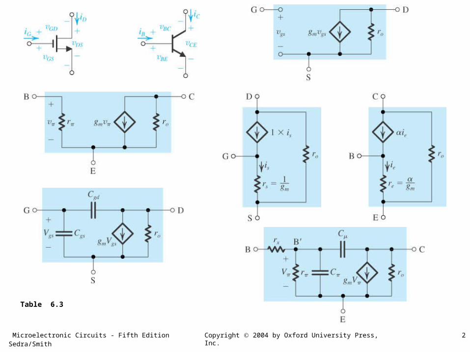
Table 6.3
Microelectronic Circuits - Fifth Edition Sedra/Smith 3Copyright 2004 by Oxford University Press, Inc.
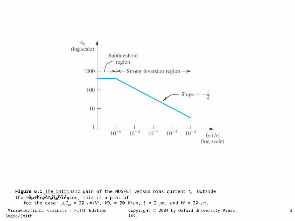
Figure 6.1 The intrinsic gain of the MOSFET versus bias current ID. Outside the subthreshold region, this is a plot of for the case: nCox = 20 A/V2, V9A = 20 V/m, L = 2 m, and W = 20 m.0 2 /A Dn oxA V C WL I
Microelectronic Circuits - Fifth Edition Sedra/Smith 4Copyright 2004 by Oxford University Press, Inc.
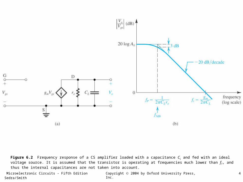
Figure 6.2 Frequency response of a CS amplifier loaded with a capacitance CL and fed with an ideal voltage source. It is assumed that the transistor is operating at frequencies much lower than fT, and thus the internal capacitances are not taken into account.
Microelectronic Circuits - Fifth Edition Sedra/Smith 5Copyright 2004 by Oxford University Press, Inc.
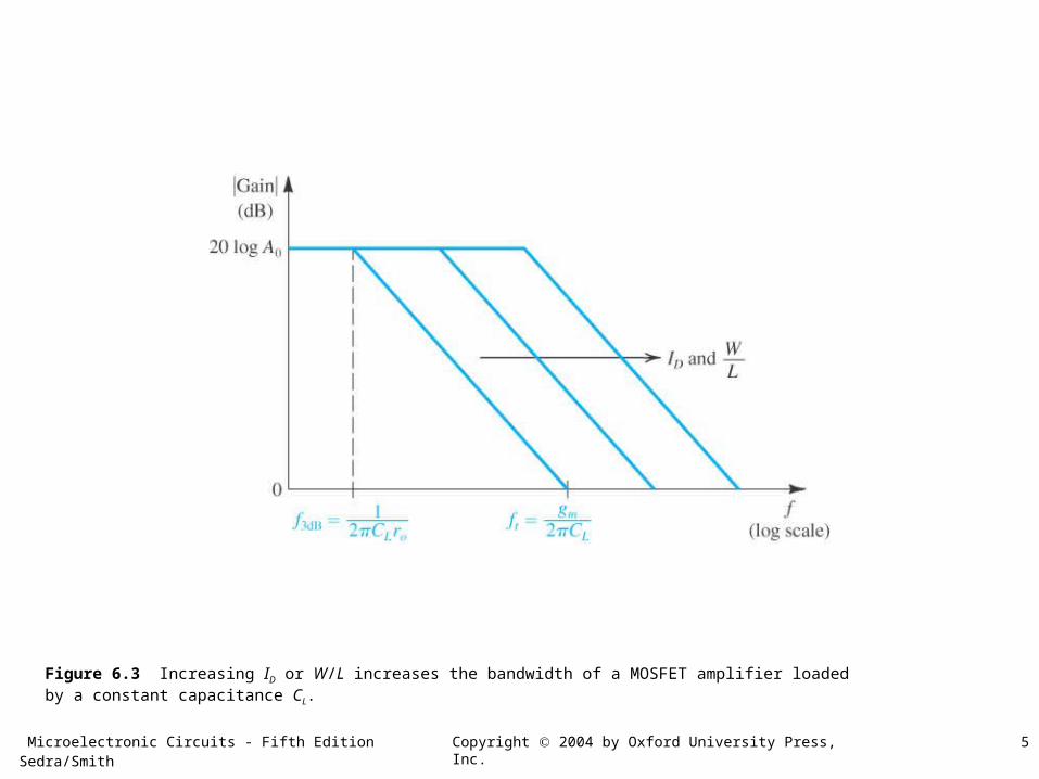
Figure 6.3 Increasing ID or W/L increases the bandwidth of a MOSFET amplifier loaded by a constant capacitance CL.
Microelectronic Circuits - Fifth Edition Sedra/Smith 6Copyright 2004 by Oxford University Press, Inc.
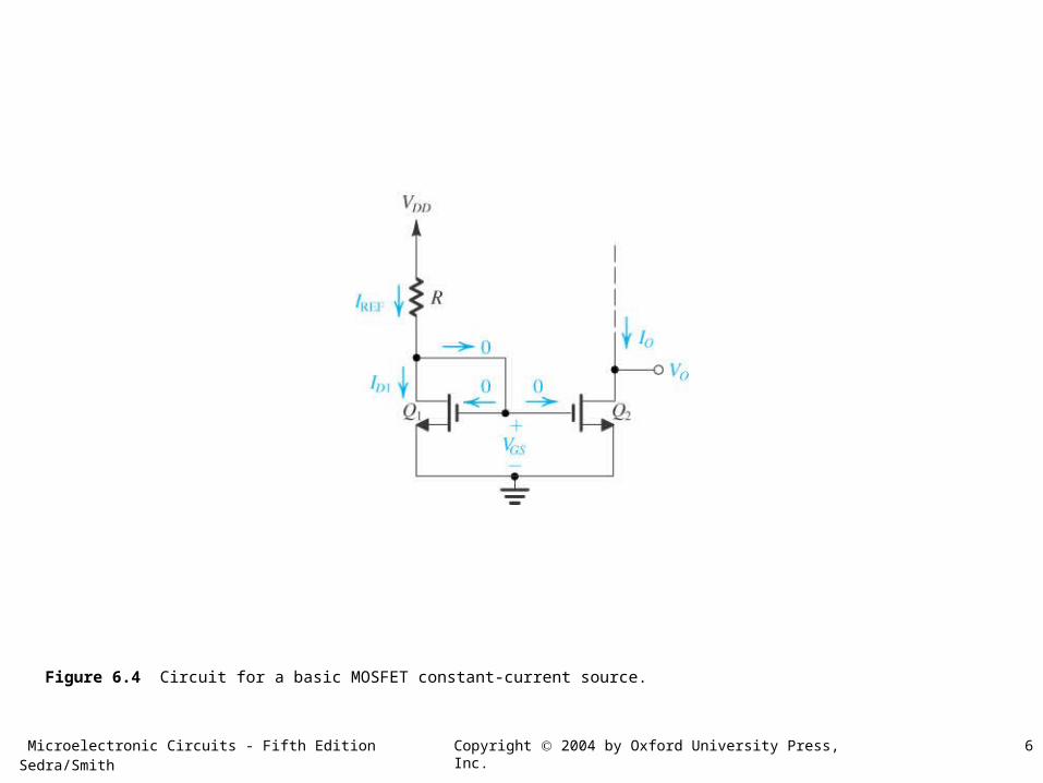
Figure 6.4 Circuit for a basic MOSFET constant-current source.
Microelectronic Circuits - Fifth Edition Sedra/Smith 7Copyright 2004 by Oxford University Press, Inc.
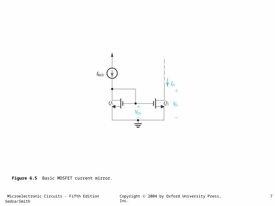
Figure 6.5 Basic MOSFET current mirror.
Microelectronic Circuits - Fifth Edition Sedra/Smith 8Copyright 2004 by Oxford University Press, Inc.
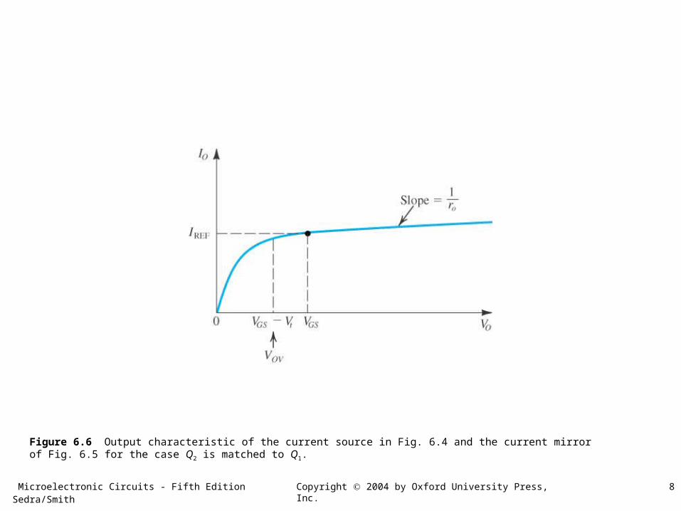
Figure 6.6 Output characteristic of the current source in Fig. 6.4 and the current mirror of Fig. 6.5 for the case Q2 is matched to Q1.
Microelectronic Circuits - Fifth Edition Sedra/Smith 9Copyright 2004 by Oxford University Press, Inc.
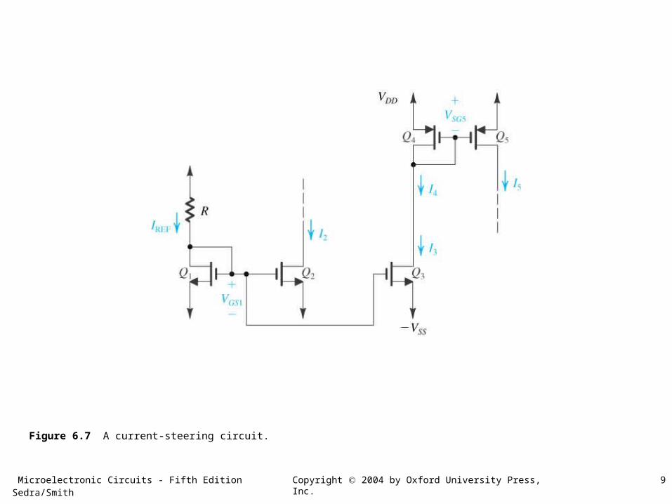
Figure 6.7 A current-steering circuit.
Microelectronic Circuits - Fifth Edition Sedra/Smith 10Copyright 2004 by Oxford University Press, Inc.
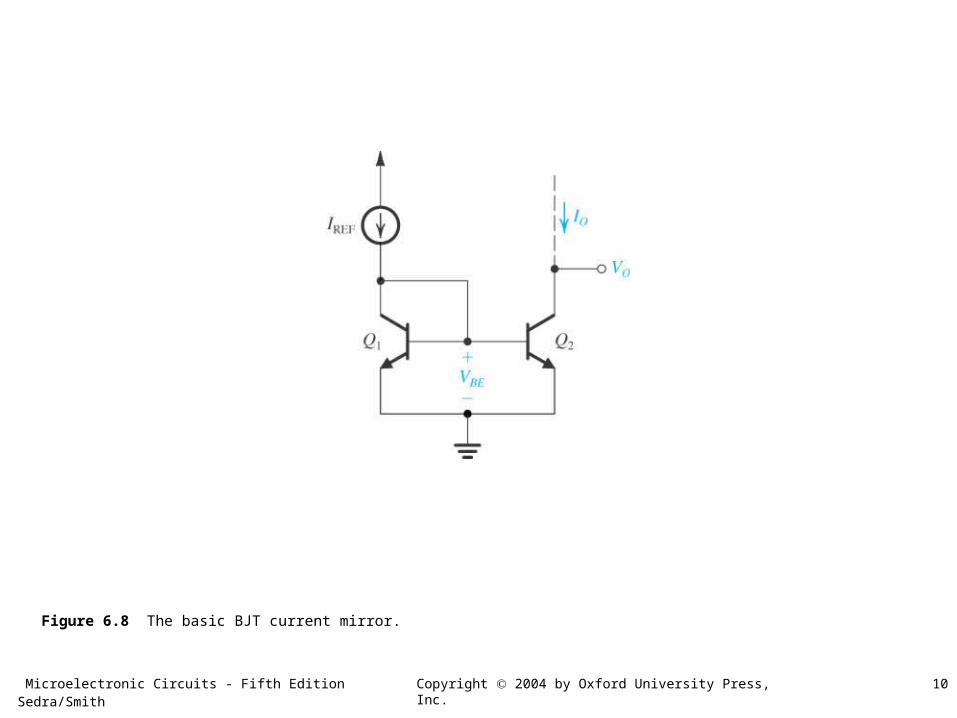
Figure 6.8 The basic BJT current mirror.
Microelectronic Circuits - Fifth Edition Sedra/Smith 11Copyright 2004 by Oxford University Press, Inc.
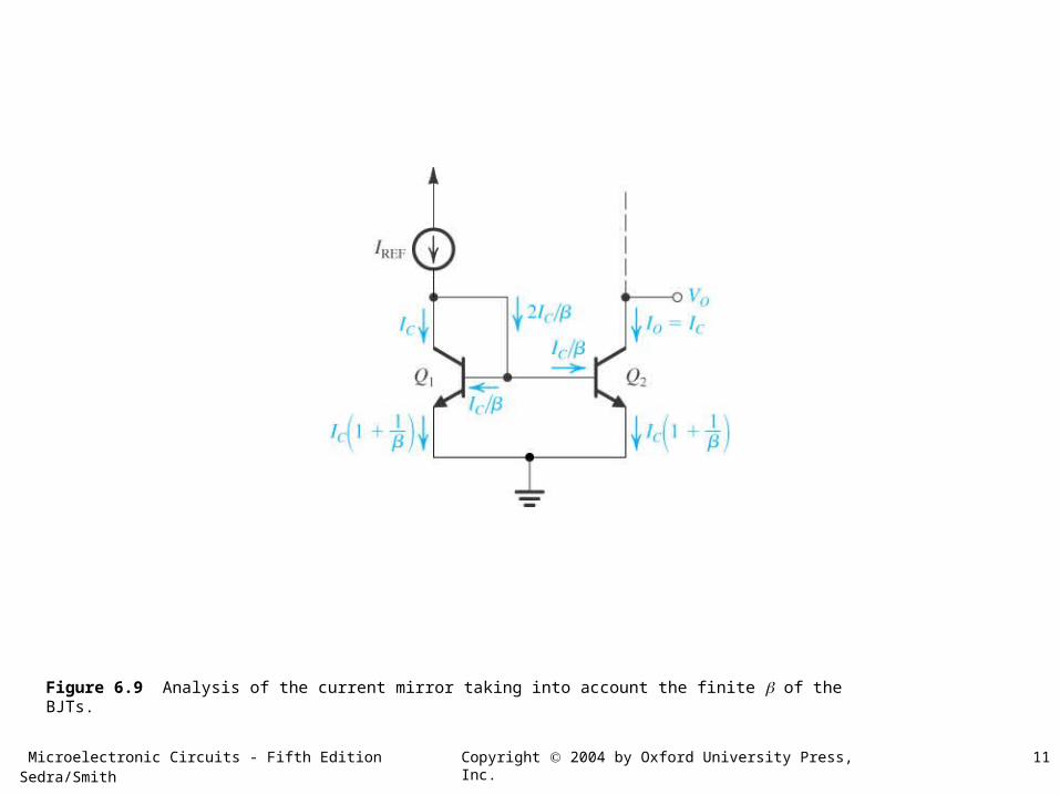
Figure 6.9 Analysis of the current mirror taking into account the finite of the BJTs.
Microelectronic Circuits - Fifth Edition Sedra/Smith 12Copyright 2004 by Oxford University Press, Inc.
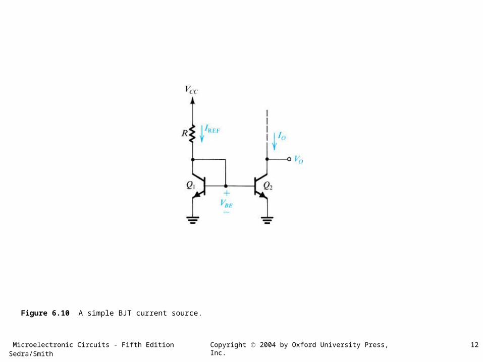
Figure 6.10 A simple BJT current source.
Microelectronic Circuits - Fifth Edition Sedra/Smith 13Copyright 2004 by Oxford University Press, Inc.
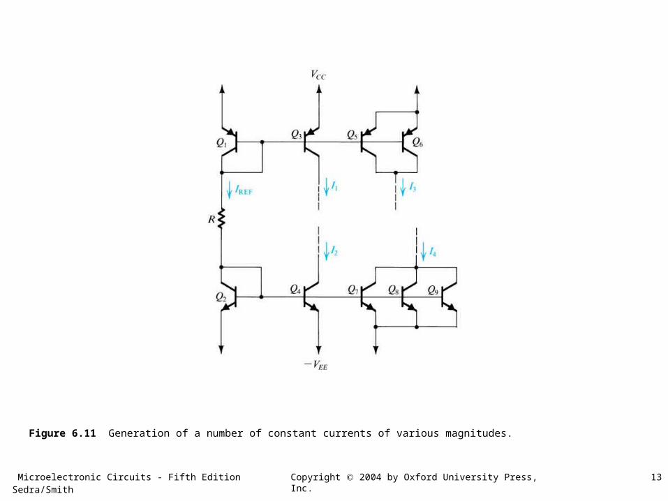
Figure 6.11 Generation of a number of constant currents of various magnitudes.
Microelectronic Circuits - Fifth Edition Sedra/Smith 14Copyright 2004 by Oxford University Press, Inc.
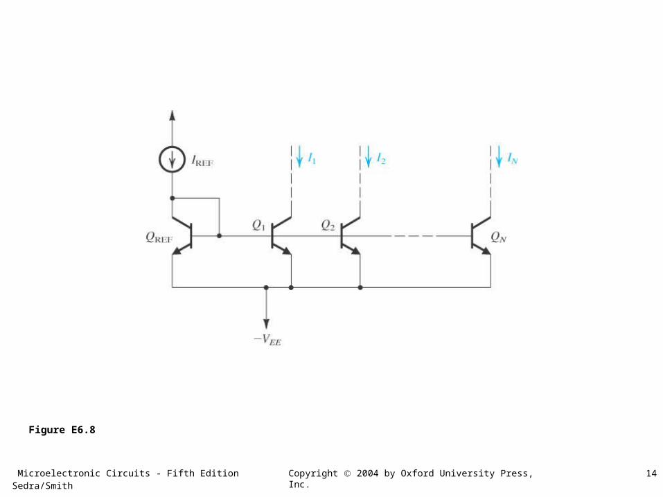
Figure E6.8
Microelectronic Circuits - Fifth Edition Sedra/Smith 15Copyright 2004 by Oxford University Press, Inc.
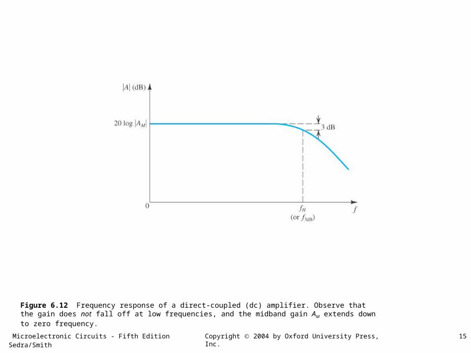
Figure 6.12 Frequency response of a direct-coupled (dc) amplifier. Observe that the gain does not fall off at low frequencies, and the midband gain AM extends down to zero frequency.
Microelectronic Circuits - Fifth Edition Sedra/Smith 16Copyright 2004 by Oxford University Press, Inc.
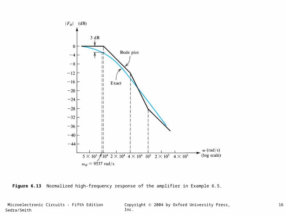
Figure 6.13 Normalized high-frequency response of the amplifier in Example 6.5.
Microelectronic Circuits - Fifth Edition Sedra/Smith 17Copyright 2004 by Oxford University Press, Inc.
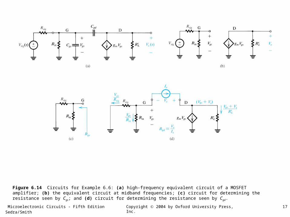
Figure 6.14 Circuits for Example 6.6: (a) high-frequency equivalent circuit of a MOSFET amplifier; (b) the equivalent circuit at midband frequencies; (c) circuit for determining the resistance seen by Cgs; and (d) circuit for determining the resistance seen by Cgd.
Microelectronic Circuits - Fifth Edition Sedra/Smith 18Copyright 2004 by Oxford University Press, Inc.
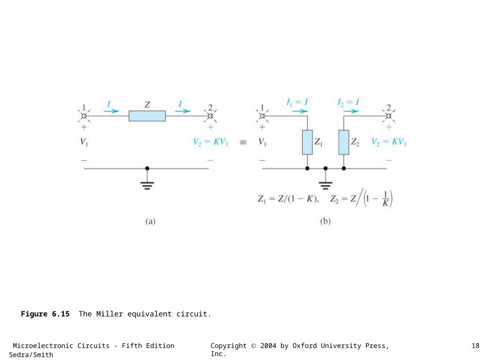
Figure 6.15 The Miller equivalent circuit.
Microelectronic Circuits - Fifth Edition Sedra/Smith 19Copyright 2004 by Oxford University Press, Inc.
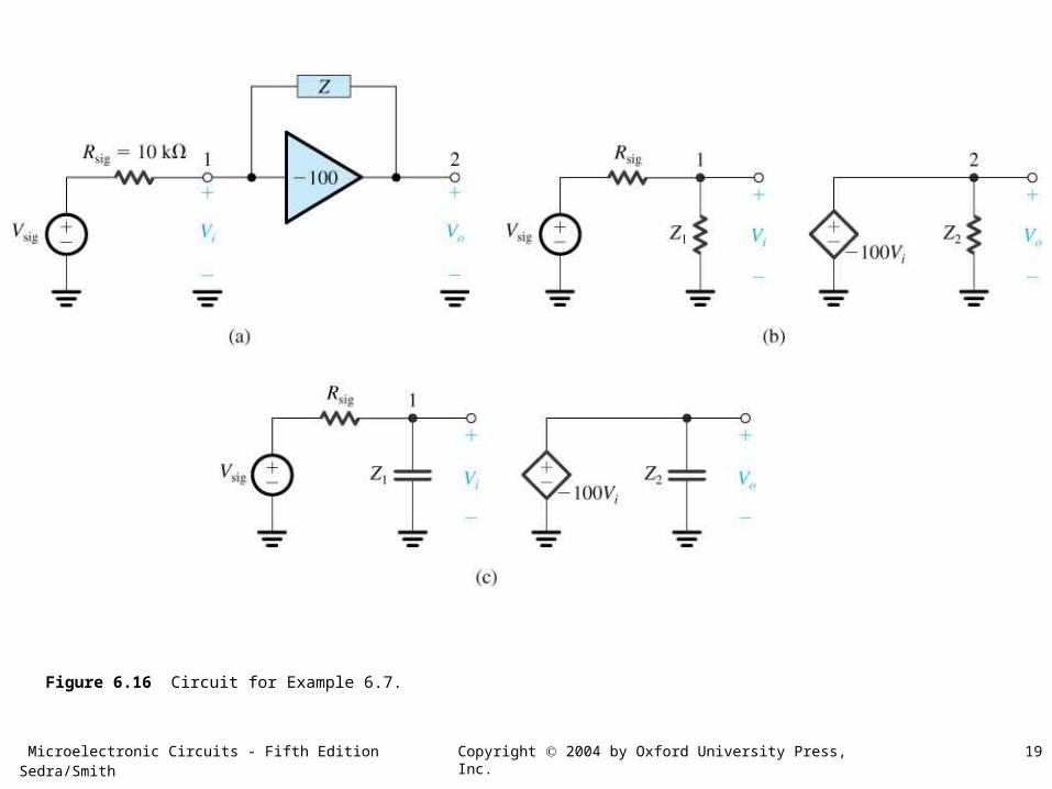
Figure 6.16 Circuit for Example 6.7.
Microelectronic Circuits - Fifth Edition Sedra/Smith 20Copyright 2004 by Oxford University Press, Inc.
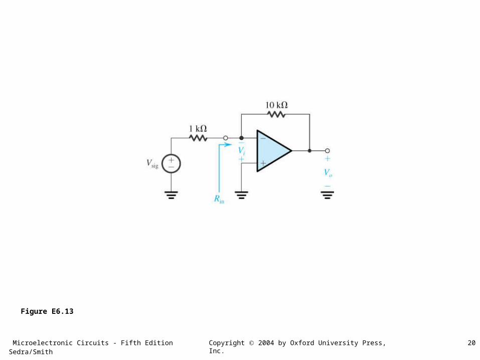
Figure E6.13
Microelectronic Circuits - Fifth Edition Sedra/Smith 21Copyright 2004 by Oxford University Press, Inc.
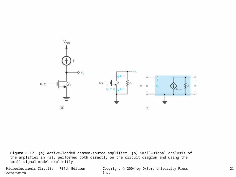
Figure 6.17 (a) Active-loaded common-source amplifier. (b) Small-signal analysis of the amplifier in (a), performed both directly on the circuit diagram and using the small-signal model explicitly.
Microelectronic Circuits - Fifth Edition Sedra/Smith 22Copyright 2004 by Oxford University Press, Inc.
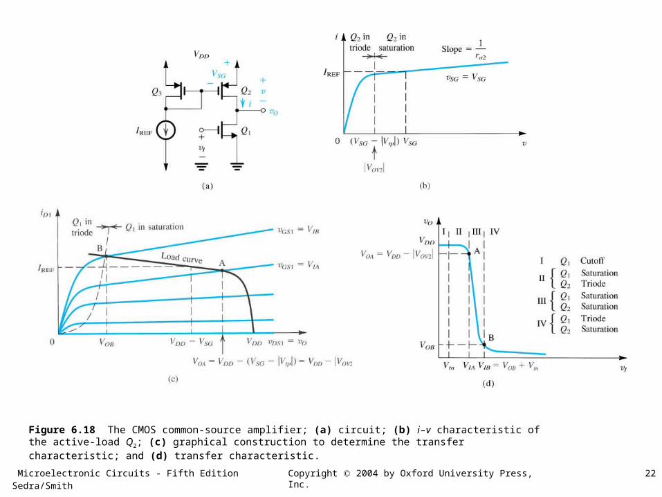
Figure 6.18 The CMOS common-source amplifier; (a) circuit; (b) i–v characteristic of the active-load Q2; (c) graphical construction to determine the transfer characteristic; and (d) transfer characteristic.
Microelectronic Circuits - Fifth Edition Sedra/Smith 23Copyright 2004 by Oxford University Press, Inc.
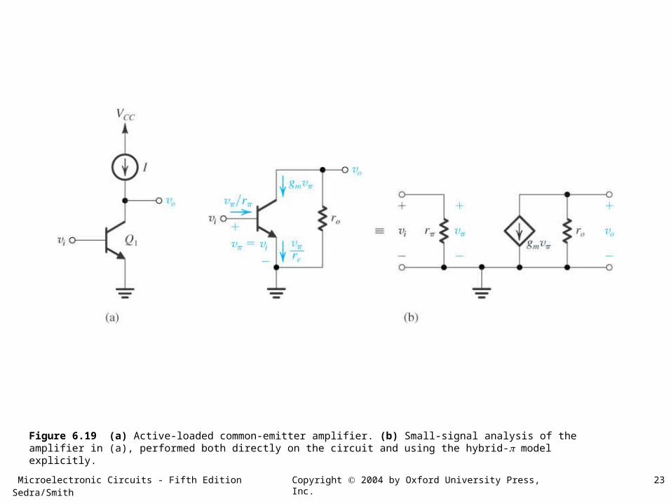
Figure 6.19 (a) Active-loaded common-emitter amplifier. (b) Small-signal analysis of the amplifier in (a), performed both directly on the circuit and using the hybrid- model explicitly.
Microelectronic Circuits - Fifth Edition Sedra/Smith 24Copyright 2004 by Oxford University Press, Inc.
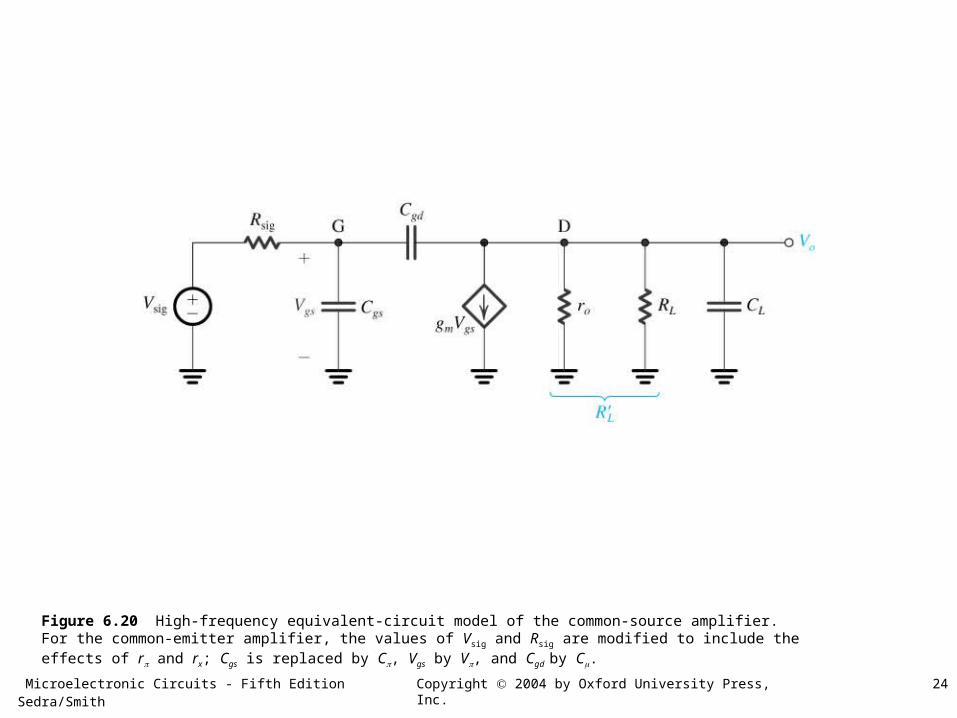
Figure 6.20 High-frequency equivalent-circuit model of the common-source amplifier. For the common-emitter amplifier, the values of Vsig and Rsig are modified to include the effects of r and rx; Cgs is replaced by C, Vgs by V, and Cgd by C.
Microelectronic Circuits - Fifth Edition Sedra/Smith 25Copyright 2004 by Oxford University Press, Inc.
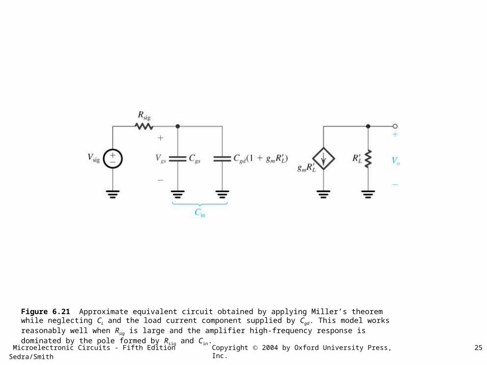
Figure 6.21 Approximate equivalent circuit obtained by applying Miller’s theorem while neglecting CL and the load current component supplied by Cgd. This model works reasonably well when Rsig is large and the amplifier high-frequency response is dominated by the pole formed by Rsig and Cin.
Microelectronic Circuits - Fifth Edition Sedra/Smith 26Copyright 2004 by Oxford University Press, Inc.
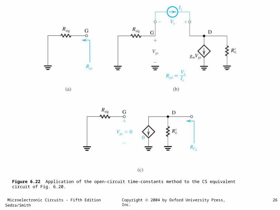
Figure 6.22 Application of the open-circuit time-constants method to the CS equivalent circuit of Fig. 6.20.
Microelectronic Circuits - Fifth Edition Sedra/Smith 27Copyright 2004 by Oxford University Press, Inc.
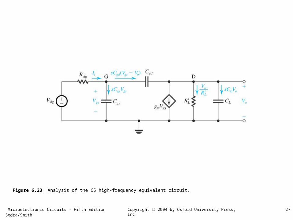
Figure 6.23 Analysis of the CS high-frequency equivalent circuit.
Microelectronic Circuits - Fifth Edition Sedra/Smith 28Copyright 2004 by Oxford University Press, Inc.
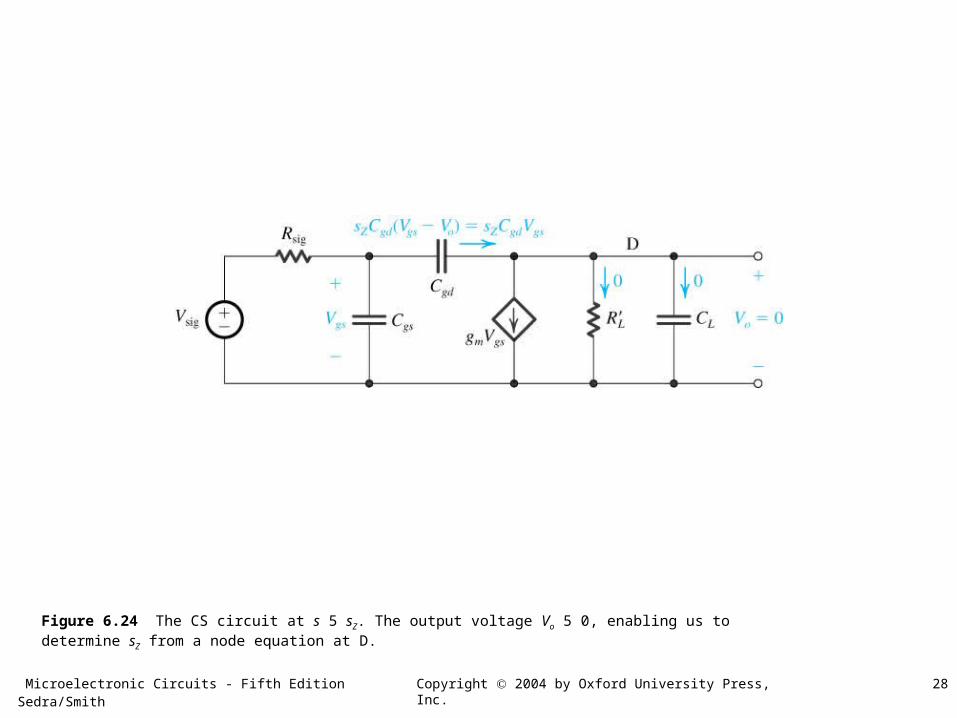
Figure 6.24 The CS circuit at s 5 sZ. The output voltage Vo 5 0, enabling us to determine sZ from a node equation at D.
Microelectronic Circuits - Fifth Edition Sedra/Smith 29Copyright 2004 by Oxford University Press, Inc.
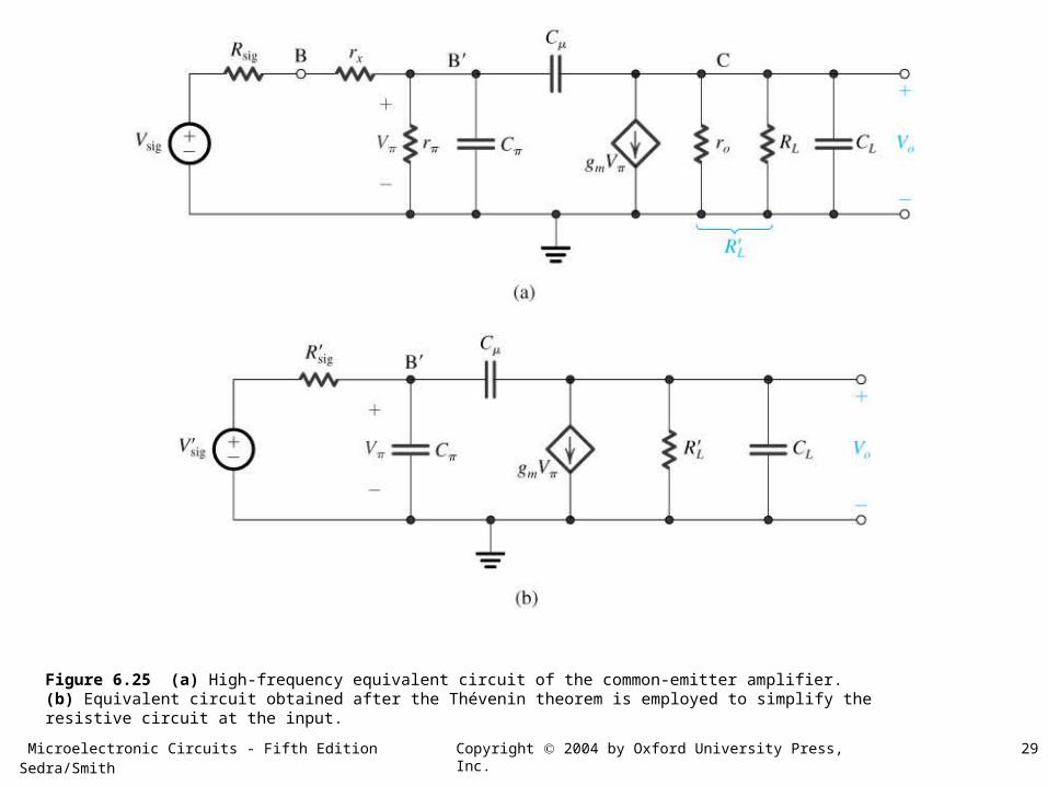
Figure 6.25 (a) High-frequency equivalent circuit of the common-emitter amplifier. (b) Equivalent circuit obtained after the Thévenin theorem is employed to simplify the resistive circuit at the input.
Microelectronic Circuits - Fifth Edition Sedra/Smith 30Copyright 2004 by Oxford University Press, Inc.
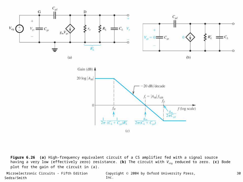
Figure 6.26 (a) High-frequency equivalent circuit of a CS amplifier fed with a signal source having a very low (effectively zero) resistance. (b) The circuit with Vsig reduced to zero. (c) Bode plot for the gain of the circuit in (a).
Microelectronic Circuits - Fifth Edition Sedra/Smith 31Copyright 2004 by Oxford University Press, Inc.
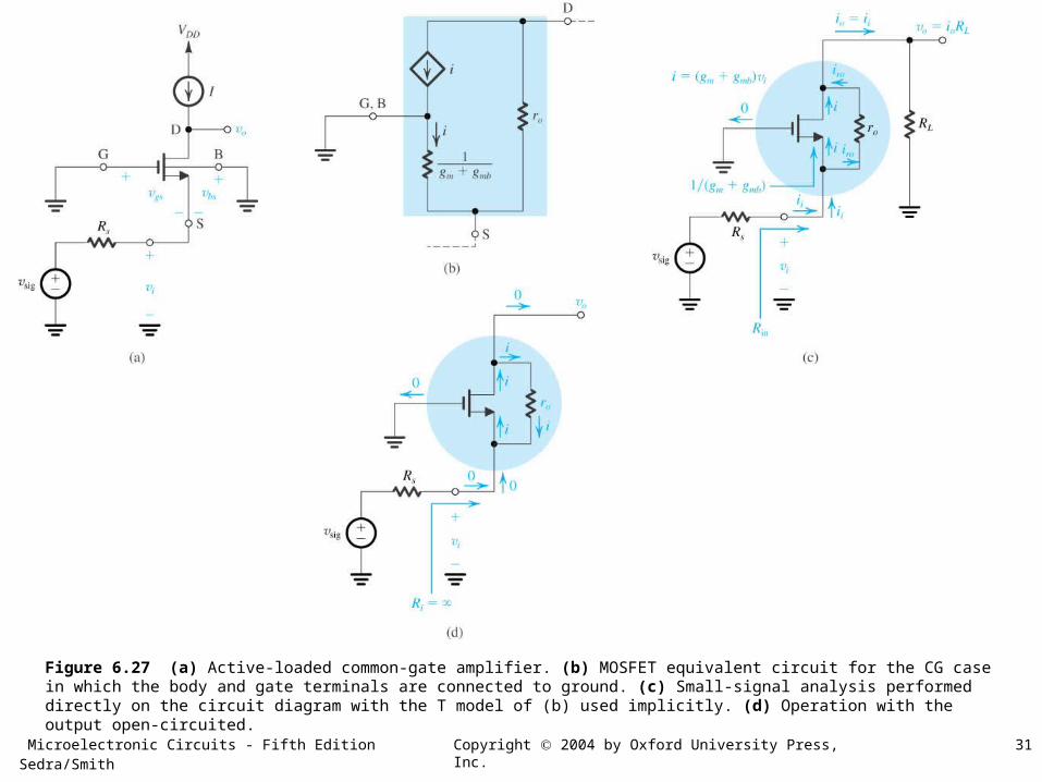
Figure 6.27 (a) Active-loaded common-gate amplifier. (b) MOSFET equivalent circuit for the CG case in which the body and gate terminals are connected to ground. (c) Small-signal analysis performed directly on the circuit diagram with the T model of (b) used implicitly. (d) Operation with the output open-circuited.
Microelectronic Circuits - Fifth Edition Sedra/Smith 32Copyright 2004 by Oxford University Press, Inc.
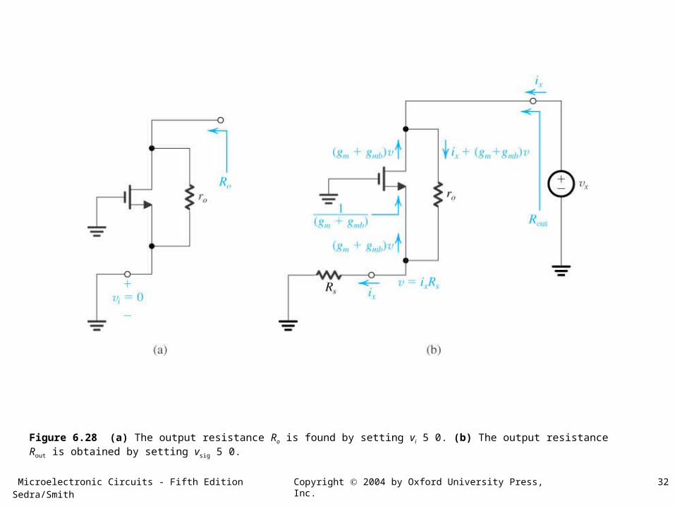
Figure 6.28 (a) The output resistance Ro is found by setting vi 5 0. (b) The output resistance Rout is obtained by setting vsig 5 0.
Microelectronic Circuits - Fifth Edition Sedra/Smith 33Copyright 2004 by Oxford University Press, Inc.
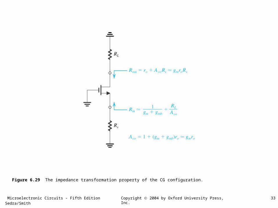
Figure 6.29 The impedance transformation property of the CG configuration.
Microelectronic Circuits - Fifth Edition Sedra/Smith 34Copyright 2004 by Oxford University Press, Inc.
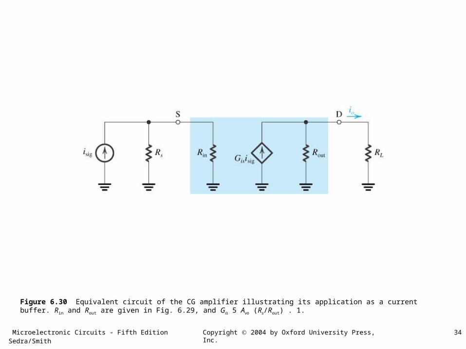
Figure 6.30 Equivalent circuit of the CG amplifier illustrating its application as a current buffer. Rin and Rout are given in Fig. 6.29, and Gis 5 Avo (Rs/Rout) . 1.
Microelectronic Circuits - Fifth Edition Sedra/Smith 35Copyright 2004 by Oxford University Press, Inc.
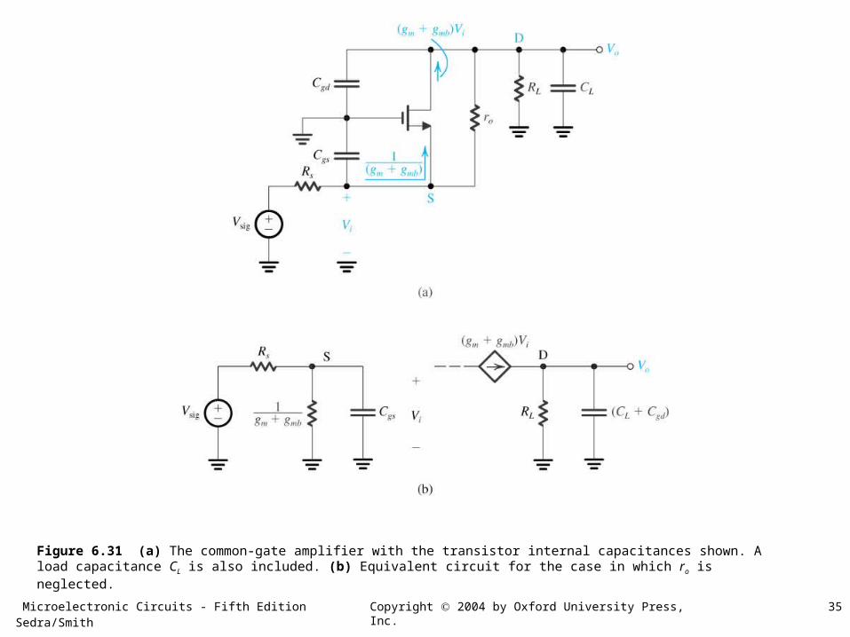
Figure 6.31 (a) The common-gate amplifier with the transistor internal capacitances shown. A load capacitance CL is also included. (b) Equivalent circuit for the case in which ro is neglected.
Microelectronic Circuits - Fifth Edition Sedra/Smith 36Copyright 2004 by Oxford University Press, Inc.
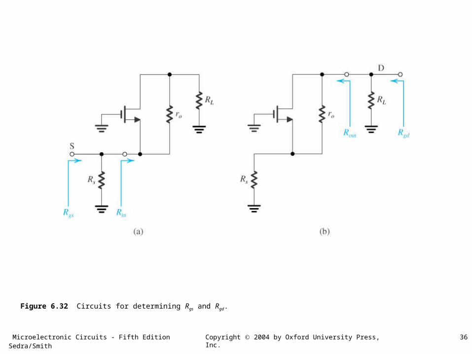
Figure 6.32 Circuits for determining Rgs and Rgd.
Microelectronic Circuits - Fifth Edition Sedra/Smith 37Copyright 2004 by Oxford University Press, Inc.
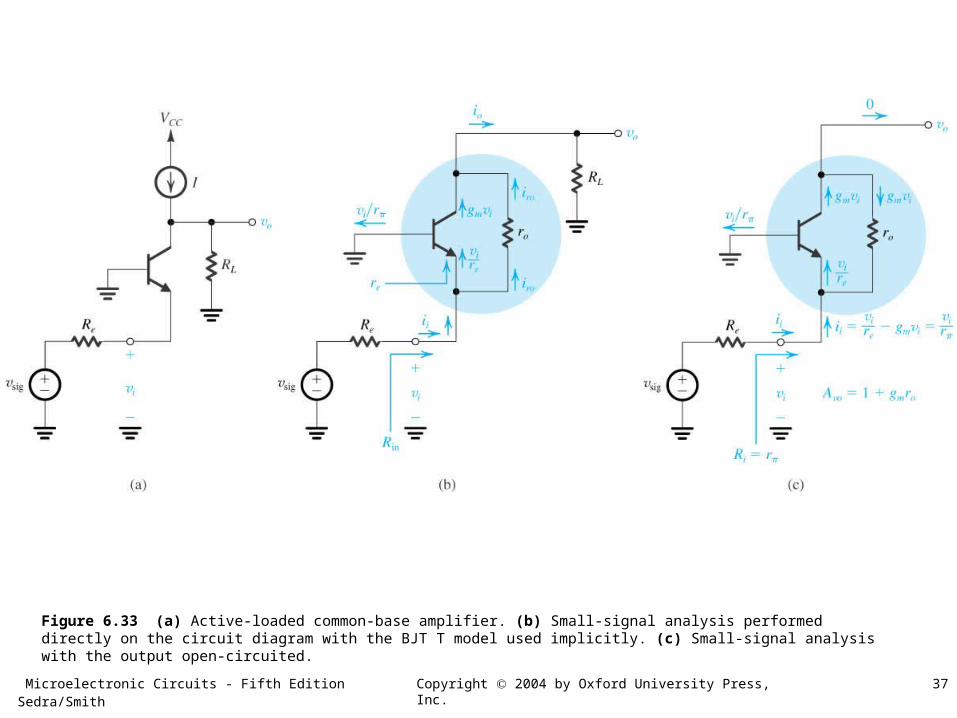
Figure 6.33 (a) Active-loaded common-base amplifier. (b) Small-signal analysis performed directly on the circuit diagram with the BJT T model used implicitly. (c) Small-signal analysis with the output open-circuited.
Microelectronic Circuits - Fifth Edition Sedra/Smith 38Copyright 2004 by Oxford University Press, Inc.
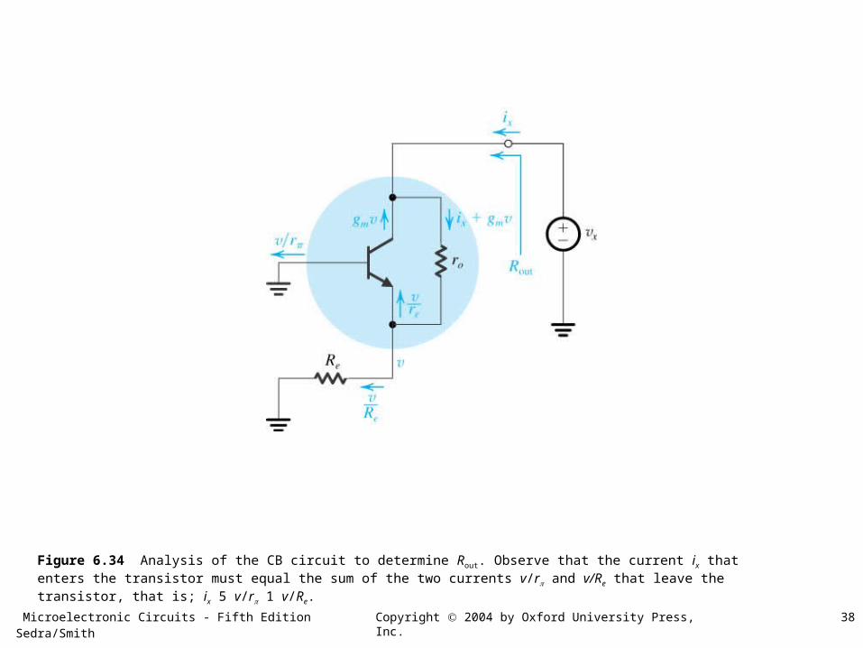
Figure 6.34 Analysis of the CB circuit to determine Rout. Observe that the current ix that enters the transistor must equal the sum of the two currents v/r and v/Re that leave the transistor, that is; ix 5 v/r 1 v/Re.
Microelectronic Circuits - Fifth Edition Sedra/Smith 39Copyright 2004 by Oxford University Press, Inc.
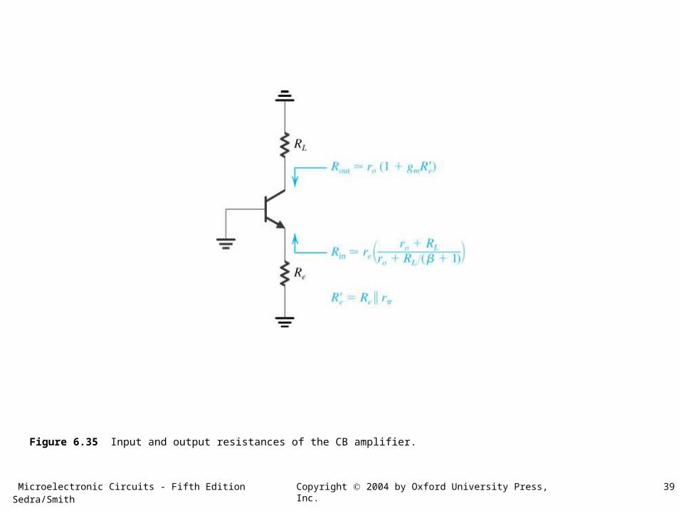
Figure 6.35 Input and output resistances of the CB amplifier.
Microelectronic Circuits - Fifth Edition Sedra/Smith 40Copyright 2004 by Oxford University Press, Inc.
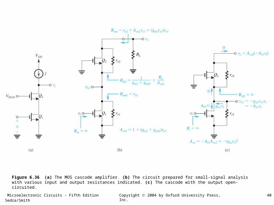
Figure 6.36 (a) The MOS cascode amplifier. (b) The circuit prepared for small-signal analysis with various input and output resistances indicated. (c) The cascode with the output open-circuited.
Microelectronic Circuits - Fifth Edition Sedra/Smith 41Copyright 2004 by Oxford University Press, Inc.
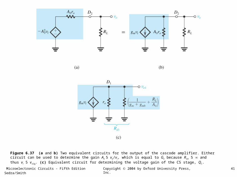
Figure 6.37 (a and b) Two equivalent circuits for the output of the cascode amplifier. Either circuit can be used to determine the gain Av 5 vo/vi, which is equal to Gv because Rin 5 and thus vi 5 vsig. (c) Equivalent circuit for determining the voltage gain of the CS stage, Q1.
Microelectronic Circuits - Fifth Edition Sedra/Smith 42Copyright 2004 by Oxford University Press, Inc.
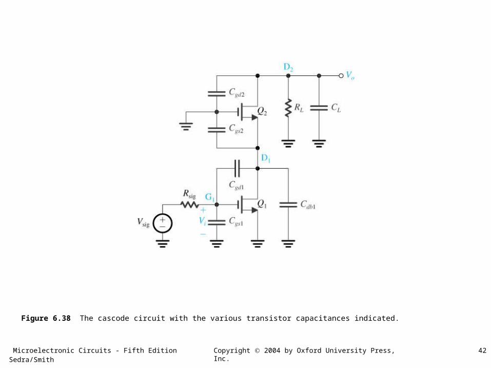
Figure 6.38 The cascode circuit with the various transistor capacitances indicated.
Microelectronic Circuits - Fifth Edition Sedra/Smith 43Copyright 2004 by Oxford University Press, Inc.
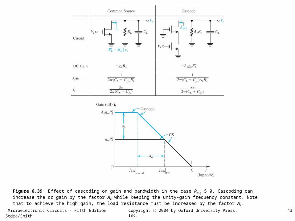
Figure 6.39 Effect of cascoding on gain and bandwidth in the case Rsig 5 0. Cascoding can increase the dc gain by the factor A0 while keeping the unity-gain frequency constant. Note that to achieve the high gain, the load resistance must be increased by the factor A0.
Microelectronic Circuits - Fifth Edition Sedra/Smith 44Copyright 2004 by Oxford University Press, Inc.
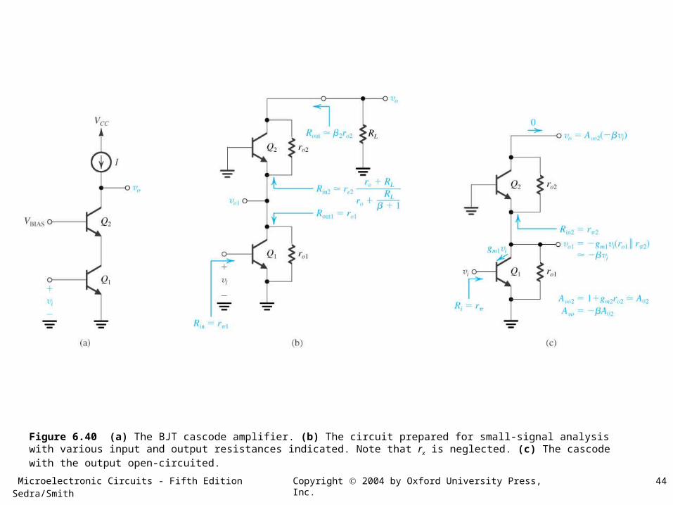
Figure 6.40 (a) The BJT cascode amplifier. (b) The circuit prepared for small-signal analysis with various input and output resistances indicated. Note that rx is neglected. (c) The cascode with the output open-circuited.
Microelectronic Circuits - Fifth Edition Sedra/Smith 45Copyright 2004 by Oxford University Press, Inc.
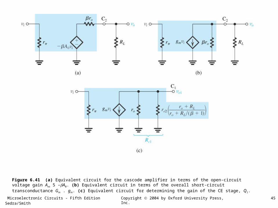
Figure 6.41 (a) Equivalent circuit for the cascode amplifier in terms of the open-circuit voltage gain Avo 5 –A0. (b) Equivalent circuit in terms of the overall short-circuit transconductance Gm . gm. (c) Equivalent circuit for determining the gain of the CE stage, Q1.
Microelectronic Circuits - Fifth Edition Sedra/Smith 46Copyright 2004 by Oxford University Press, Inc.
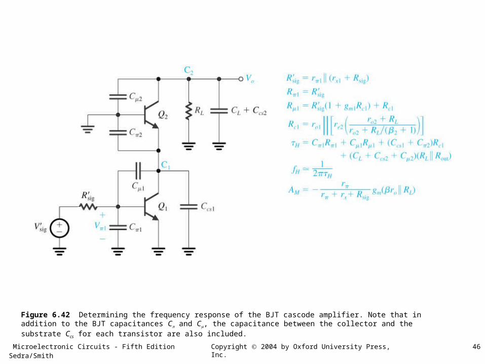
Figure 6.42 Determining the frequency response of the BJT cascode amplifier. Note that in addition to the BJT capacitances C and C, the capacitance between the collector and the substrate Ccs for each transistor are also included.
Microelectronic Circuits - Fifth Edition Sedra/Smith 47Copyright 2004 by Oxford University Press, Inc.
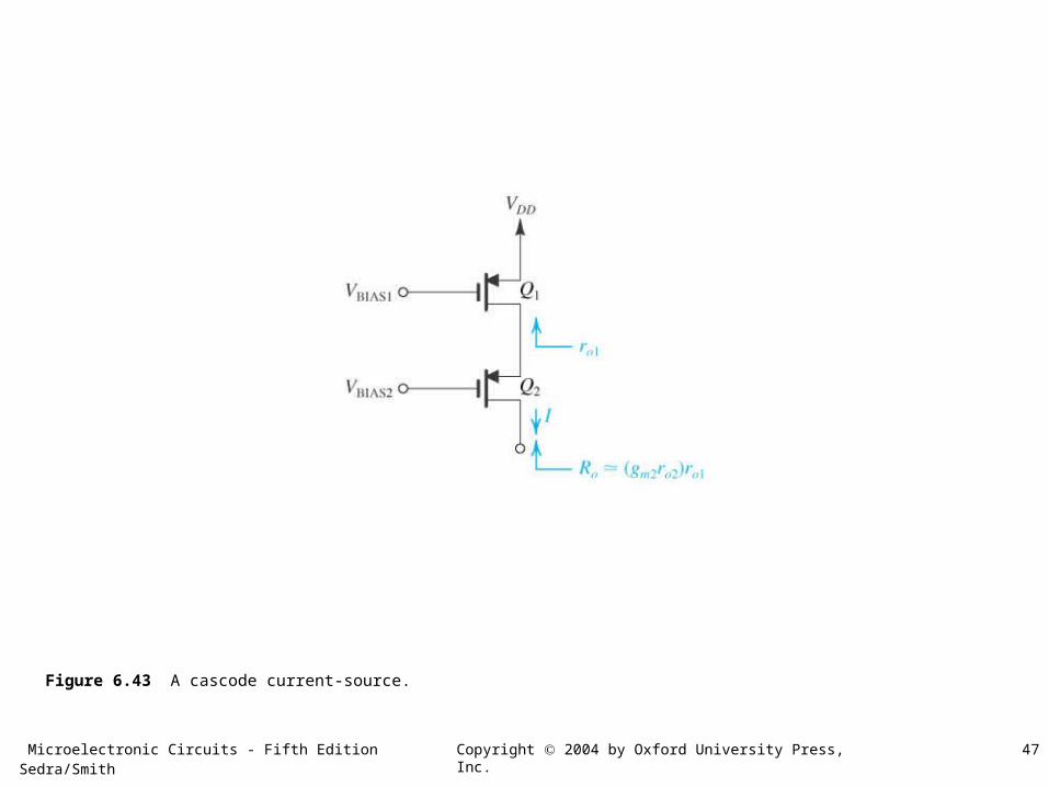
Figure 6.43 A cascode current-source.
Microelectronic Circuits - Fifth Edition Sedra/Smith 48Copyright 2004 by Oxford University Press, Inc.
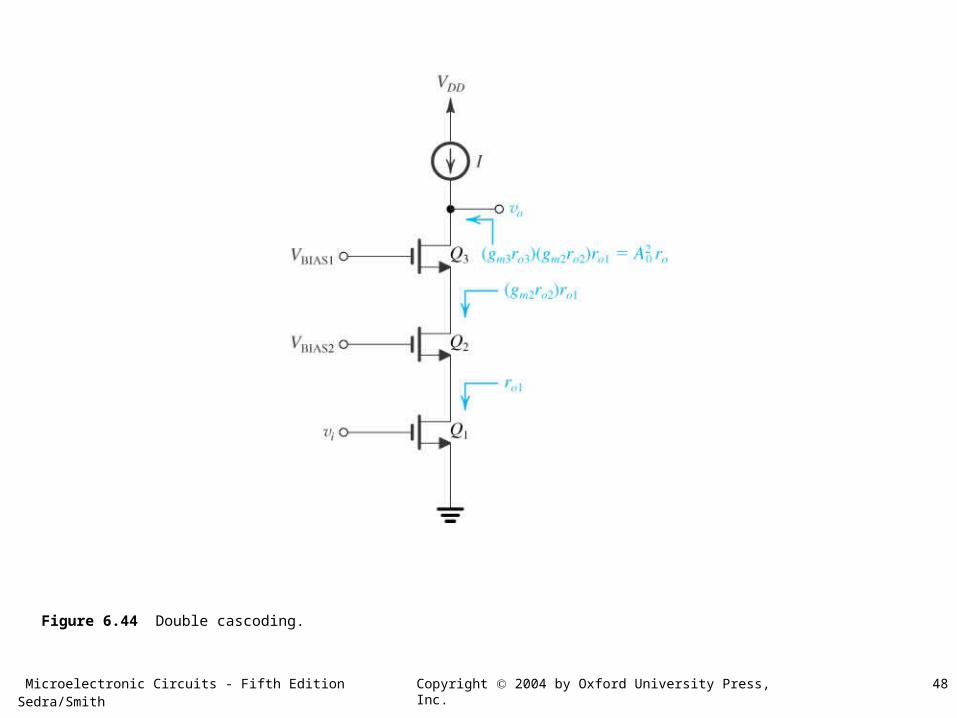
Figure 6.44 Double cascoding.
Microelectronic Circuits - Fifth Edition Sedra/Smith 49Copyright 2004 by Oxford University Press, Inc.
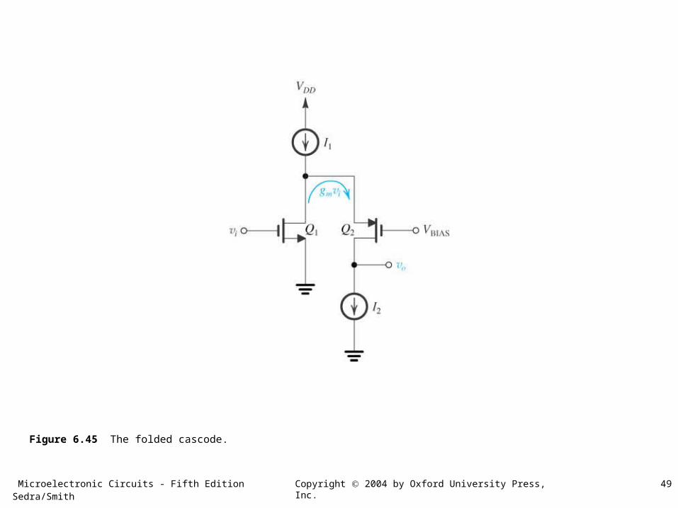
Figure 6.45 The folded cascode.
Microelectronic Circuits - Fifth Edition Sedra/Smith 50Copyright 2004 by Oxford University Press, Inc.
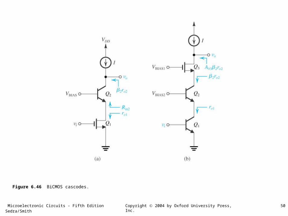
Figure 6.46 BiCMOS cascodes.
Microelectronic Circuits - Fifth Edition Sedra/Smith 51Copyright 2004 by Oxford University Press, Inc.
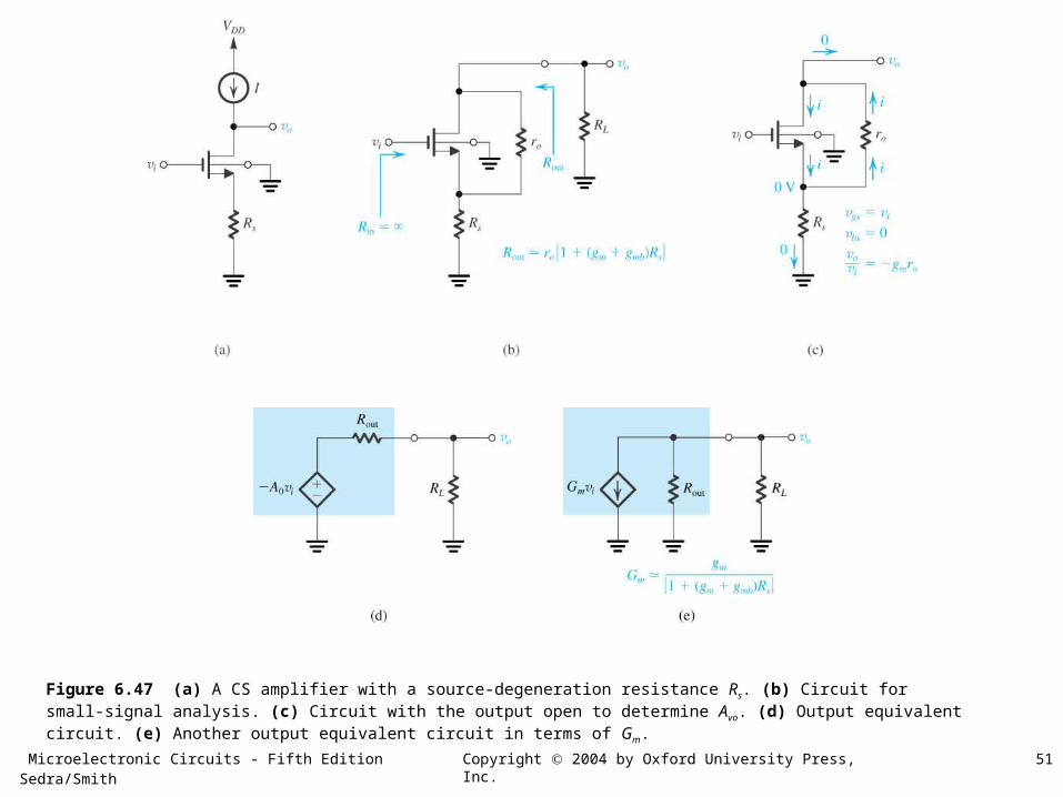
Figure 6.47 (a) A CS amplifier with a source-degeneration resistance Rs. (b) Circuit for small-signal analysis. (c) Circuit with the output open to determine Avo. (d) Output equivalent circuit. (e) Another output equivalent circuit in terms of Gm.
Microelectronic Circuits - Fifth Edition Sedra/Smith 52Copyright 2004 by Oxford University Press, Inc.
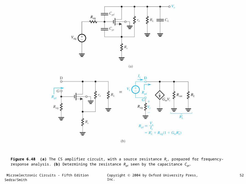
Figure 6.48 (a) The CS amplifier circuit, with a source resistance Rs, prepared for frequency-response analysis. (b) Determining the resistance Rgd seen by the capacitance Cgd.
Microelectronic Circuits - Fifth Edition Sedra/Smith 53Copyright 2004 by Oxford University Press, Inc.
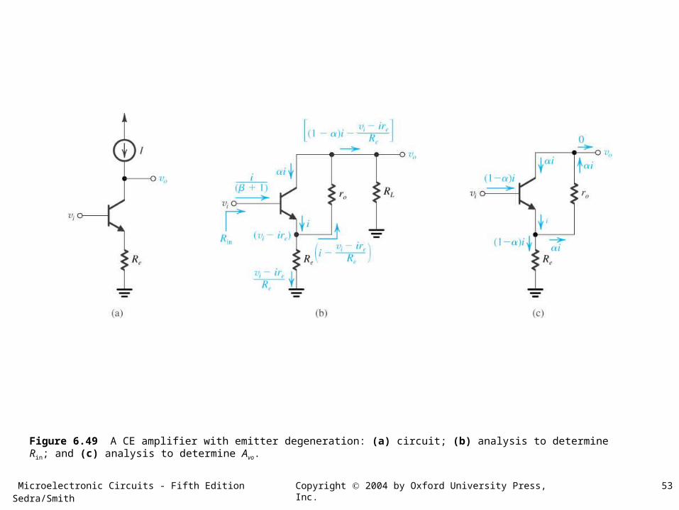
Figure 6.49 A CE amplifier with emitter degeneration: (a) circuit; (b) analysis to determine Rin; and (c) analysis to determine Avo.
Microelectronic Circuits - Fifth Edition Sedra/Smith 54Copyright 2004 by Oxford University Press, Inc.
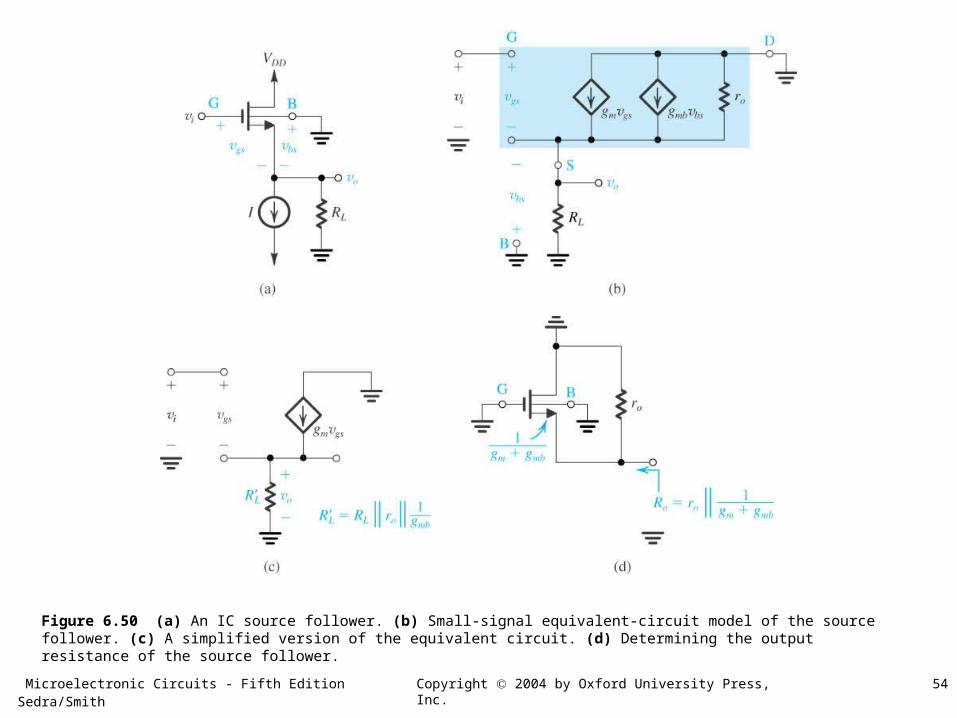
Figure 6.50 (a) An IC source follower. (b) Small-signal equivalent-circuit model of the source follower. (c) A simplified version of the equivalent circuit. (d) Determining the output resistance of the source follower.
Microelectronic Circuits - Fifth Edition Sedra/Smith 55Copyright 2004 by Oxford University Press, Inc.
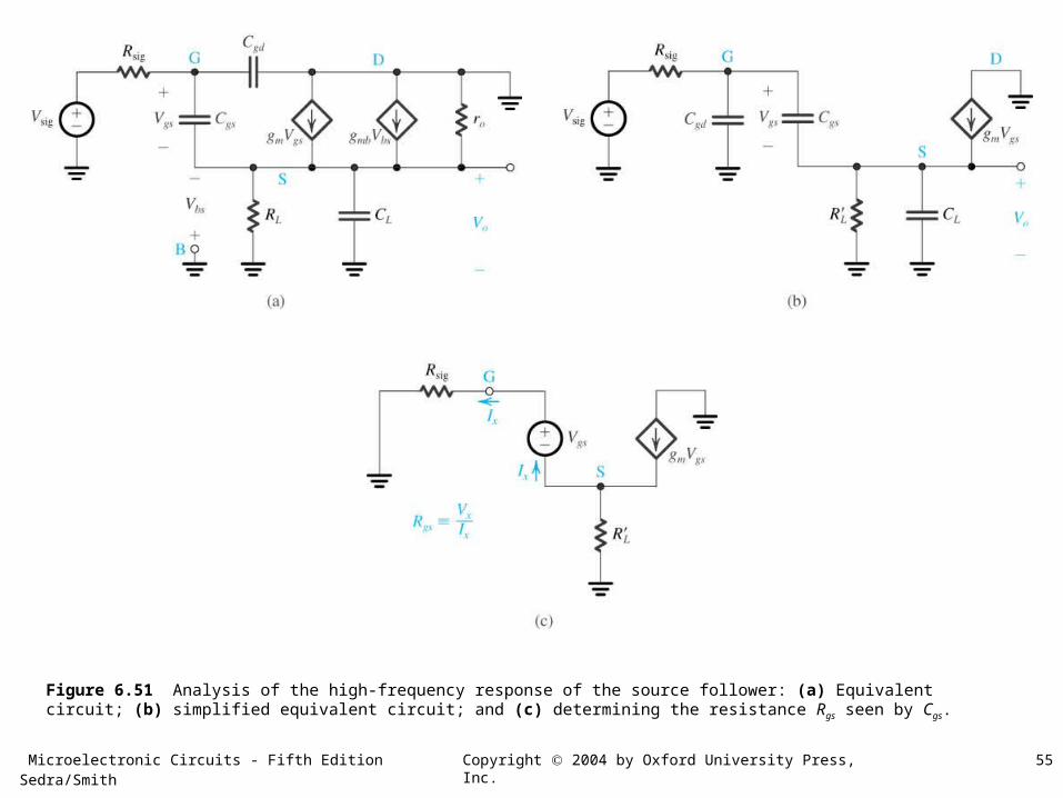
Figure 6.51 Analysis of the high-frequency response of the source follower: (a) Equivalent circuit; (b) simplified equivalent circuit; and (c) determining the resistance Rgs seen by Cgs.
Microelectronic Circuits - Fifth Edition Sedra/Smith 56Copyright 2004 by Oxford University Press, Inc.
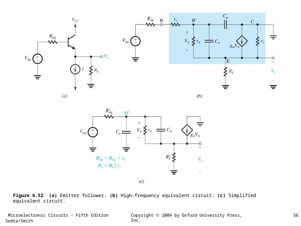
Figure 6.52 (a) Emitter follower. (b) High-frequency equivalent circuit. (c) Simplified equivalent circuit.
Microelectronic Circuits - Fifth Edition Sedra/Smith 57Copyright 2004 by Oxford University Press, Inc.
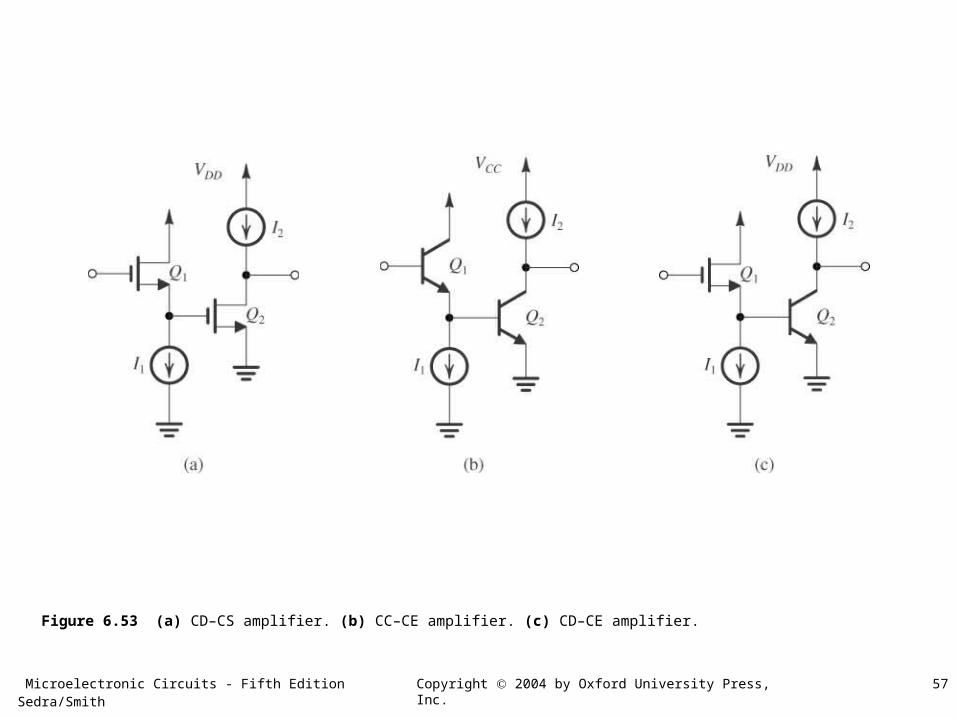
Figure 6.53 (a) CD–CS amplifier. (b) CC–CE amplifier. (c) CD–CE amplifier.
Microelectronic Circuits - Fifth Edition Sedra/Smith 58Copyright 2004 by Oxford University Press, Inc.
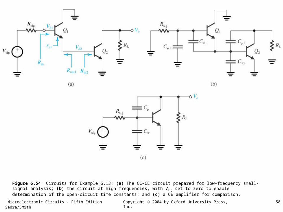
Figure 6.54 Circuits for Example 6.13: (a) The CC–CE circuit prepared for low-frequency small-signal analysis; (b) the circuit at high frequencies, with Vsig set to zero to enable determination of the open-circuit time constants; and (c) a CE amplifier for comparison.
Microelectronic Circuits - Fifth Edition Sedra/Smith 59Copyright 2004 by Oxford University Press, Inc.
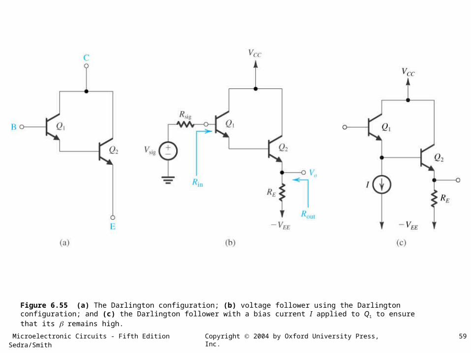
Figure 6.55 (a) The Darlington configuration; (b) voltage follower using the Darlington configuration; and (c) the Darlington follower with a bias current I applied to Q1 to ensure that its remains high.
Microelectronic Circuits - Fifth Edition Sedra/Smith 60Copyright 2004 by Oxford University Press, Inc.
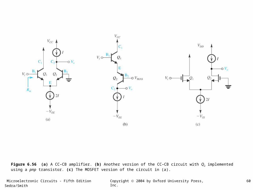
Figure 6.56 (a) A CC–CB amplifier. (b) Another version of the CC–CB circuit with Q2 implemented using a pnp transistor. (c) The MOSFET version of the circuit in (a).
Microelectronic Circuits - Fifth Edition Sedra/Smith 61Copyright 2004 by Oxford University Press, Inc.
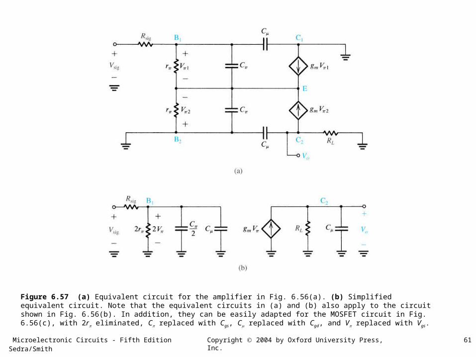
Figure 6.57 (a) Equivalent circuit for the amplifier in Fig. 6.56(a). (b) Simplified equivalent circuit. Note that the equivalent circuits in (a) and (b) also apply to the circuit shown in Fig. 6.56(b). In addition, they can be easily adapted for the MOSFET circuit in Fig. 6.56(c), with 2r eliminated, C replaced with Cgs, C replaced with Cgd, and V replaced with Vgs.
Microelectronic Circuits - Fifth Edition Sedra/Smith 62Copyright 2004 by Oxford University Press, Inc.
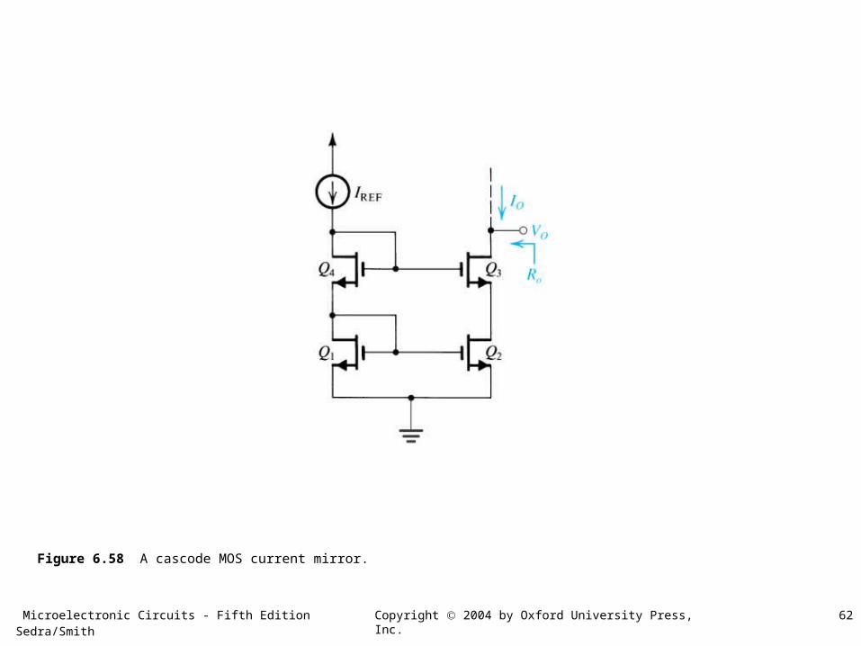
Figure 6.58 A cascode MOS current mirror.
Microelectronic Circuits - Fifth Edition Sedra/Smith 63Copyright 2004 by Oxford University Press, Inc.
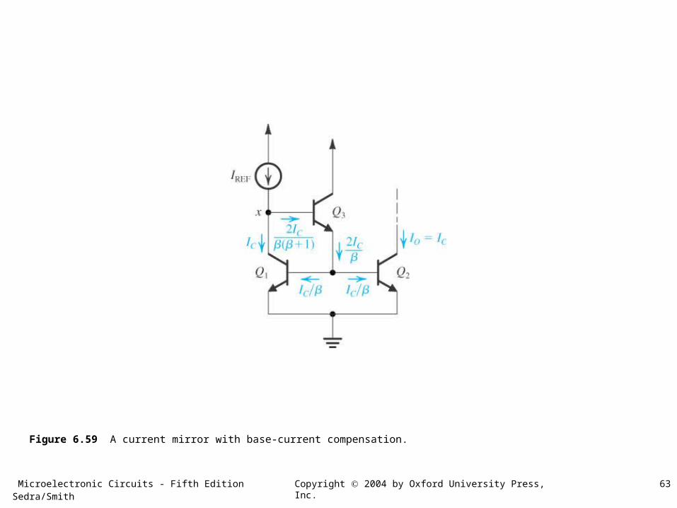
Figure 6.59 A current mirror with base-current compensation.
Microelectronic Circuits - Fifth Edition Sedra/Smith 64Copyright 2004 by Oxford University Press, Inc.
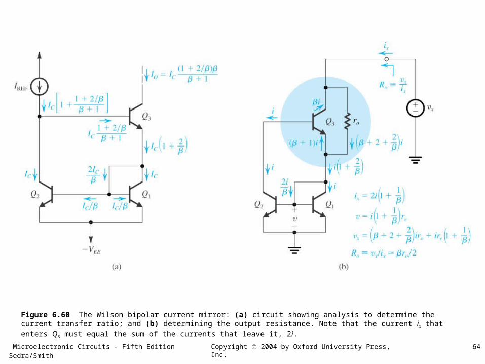
Figure 6.60 The Wilson bipolar current mirror: (a) circuit showing analysis to determine the current transfer ratio; and (b) determining the output resistance. Note that the current ix that enters Q3 must equal the sum of the currents that leave it, 2i.
Microelectronic Circuits - Fifth Edition Sedra/Smith 65Copyright 2004 by Oxford University Press, Inc.
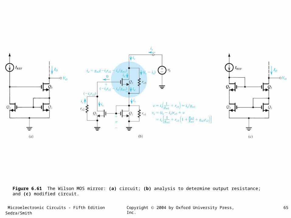
Figure 6.61 The Wilson MOS mirror: (a) circuit; (b) analysis to determine output resistance; and (c) modified circuit.
Microelectronic Circuits - Fifth Edition Sedra/Smith 66Copyright 2004 by Oxford University Press, Inc.
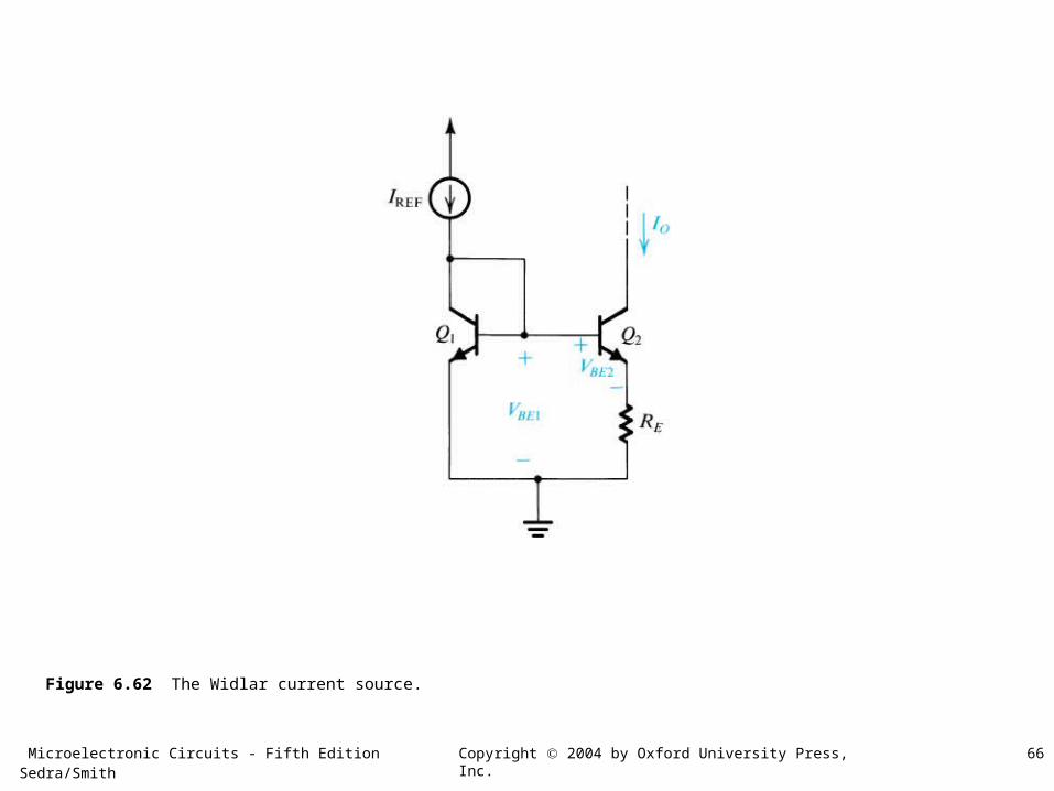
Figure 6.62 The Widlar current source.
Microelectronic Circuits - Fifth Edition Sedra/Smith 67Copyright 2004 by Oxford University Press, Inc.
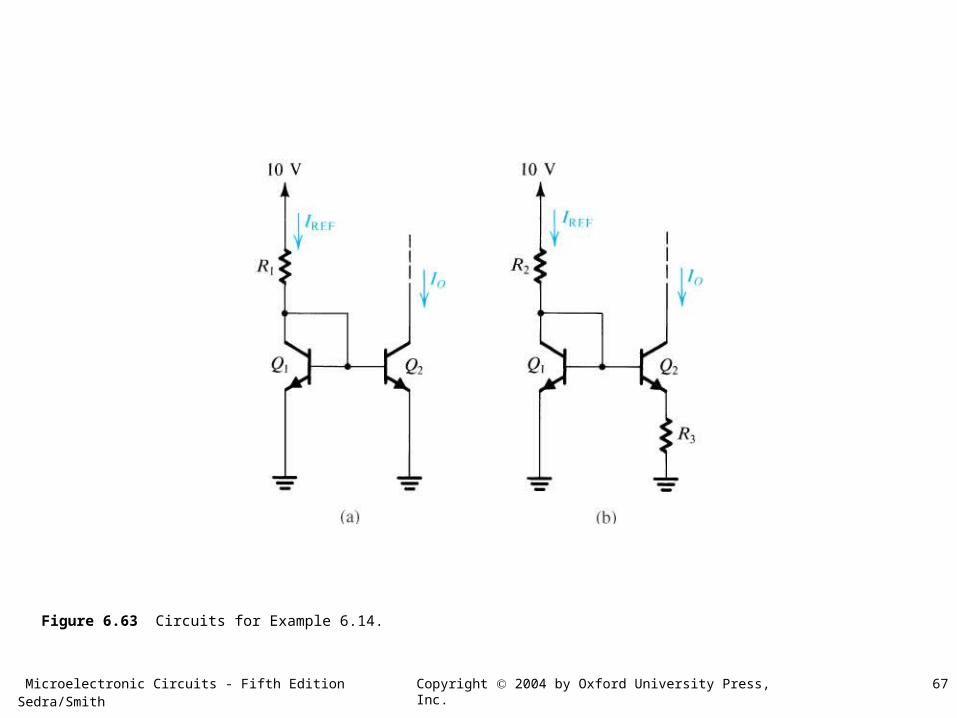
Figure 6.63 Circuits for Example 6.14.
Microelectronic Circuits - Fifth Edition Sedra/Smith 68Copyright 2004 by Oxford University Press, Inc.
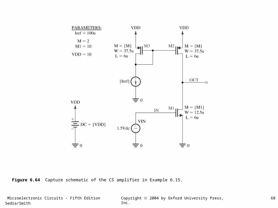
Figure 6.64 Capture schematic of the CS amplifier in Example 6.15.
Microelectronic Circuits - Fifth Edition Sedra/Smith 69Copyright 2004 by Oxford University Press, Inc.
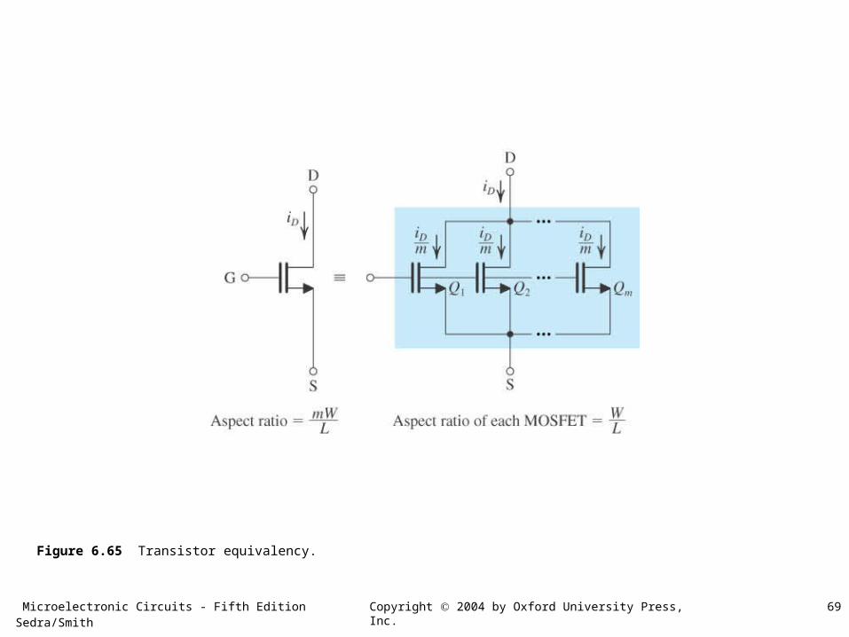
Figure 6.65 Transistor equivalency.
Microelectronic Circuits - Fifth Edition Sedra/Smith 70Copyright 2004 by Oxford University Press, Inc.
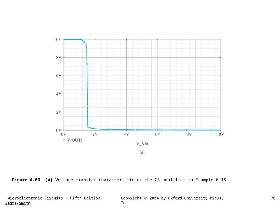
Figure 6.66 (a) Voltage transfer characteristic of the CS amplifier in Example 6.15.
Microelectronic Circuits - Fifth Edition Sedra/Smith 71Copyright 2004 by Oxford University Press, Inc.
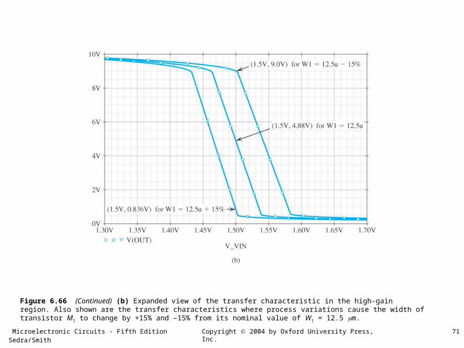
Figure 6.66 (Continued) (b) Expanded view of the transfer characteristic in the high-gain region. Also shown are the transfer characteristics where process variations cause the width of transistor M1 to change by +15% and –15% from its nominal value of W1 = 12.5 m.
Microelectronic Circuits - Fifth Edition Sedra/Smith 72Copyright 2004 by Oxford University Press, Inc.
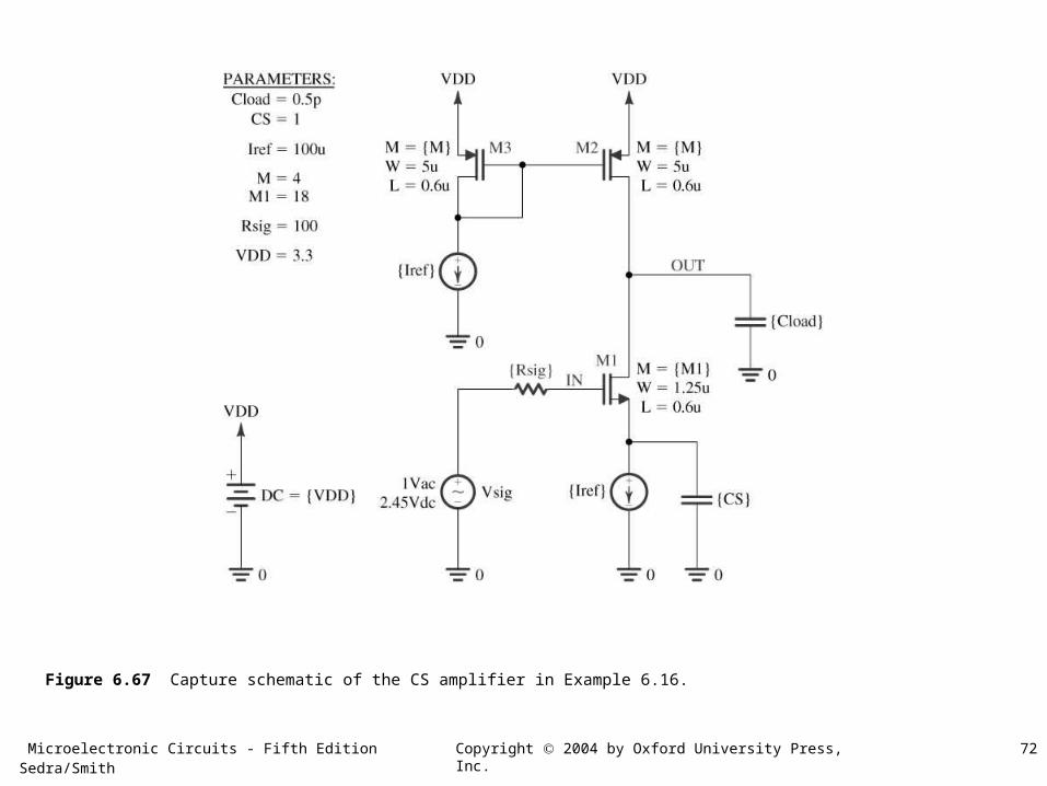
Figure 6.67 Capture schematic of the CS amplifier in Example 6.16.
Microelectronic Circuits - Fifth Edition Sedra/Smith 73Copyright 2004 by Oxford University Press, Inc.
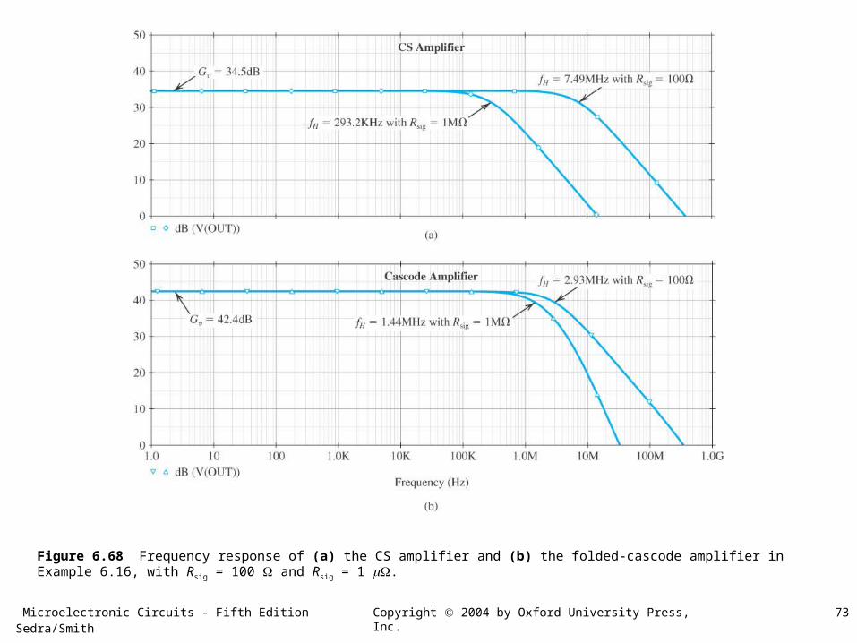
Figure 6.68 Frequency response of (a) the CS amplifier and (b) the folded-cascode amplifier in Example 6.16, with Rsig = 100 and Rsig = 1 .
Microelectronic Circuits - Fifth Edition Sedra/Smith 74Copyright 2004 by Oxford University Press, Inc.
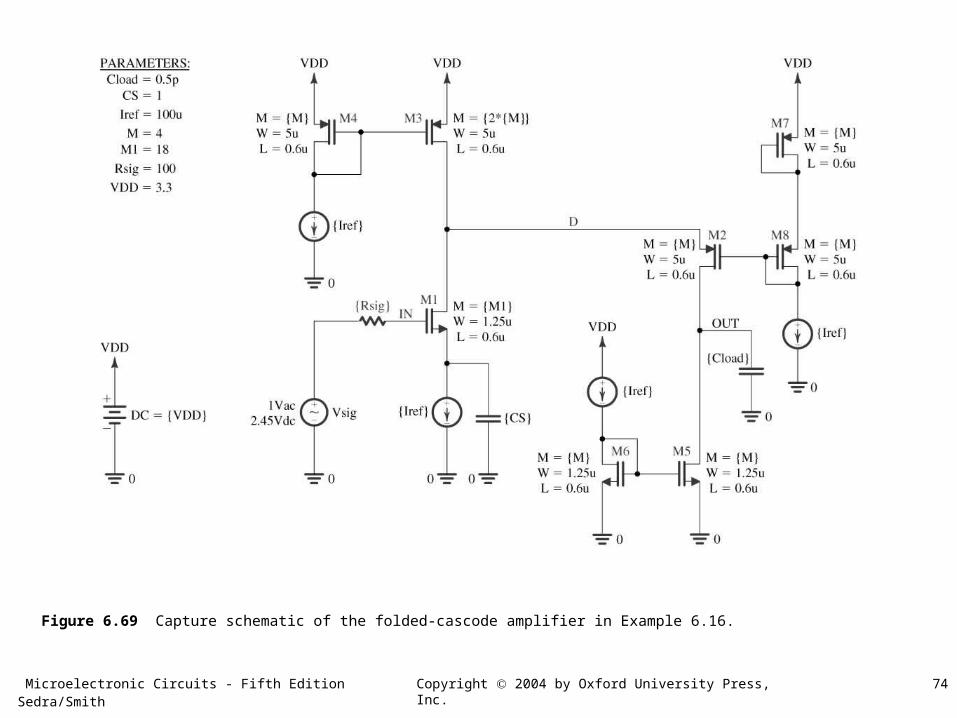
Figure 6.69 Capture schematic of the folded-cascode amplifier in Example 6.16.
Microelectronic Circuits - Fifth Edition Sedra/Smith 75Copyright 2004 by Oxford University Press, Inc.
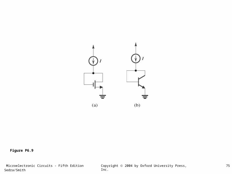
Figure P6.9
Microelectronic Circuits - Fifth Edition Sedra/Smith 76Copyright 2004 by Oxford University Press, Inc.
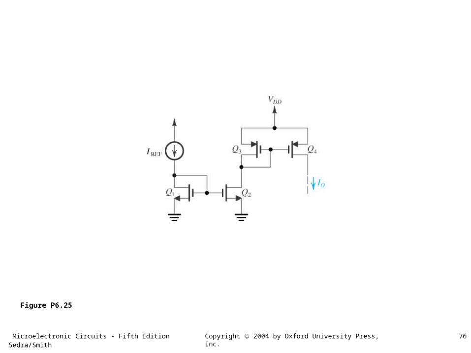
Figure P6.25
Microelectronic Circuits - Fifth Edition Sedra/Smith 77Copyright 2004 by Oxford University Press, Inc.
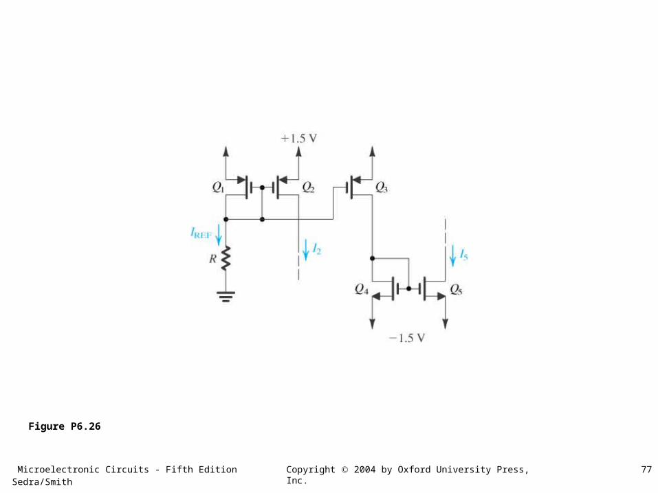
Figure P6.26
Microelectronic Circuits - Fifth Edition Sedra/Smith 78Copyright 2004 by Oxford University Press, Inc.
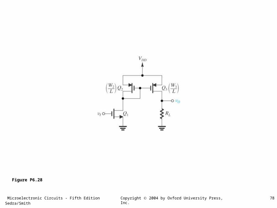
Figure P6.28
Microelectronic Circuits - Fifth Edition Sedra/Smith 79Copyright 2004 by Oxford University Press, Inc.
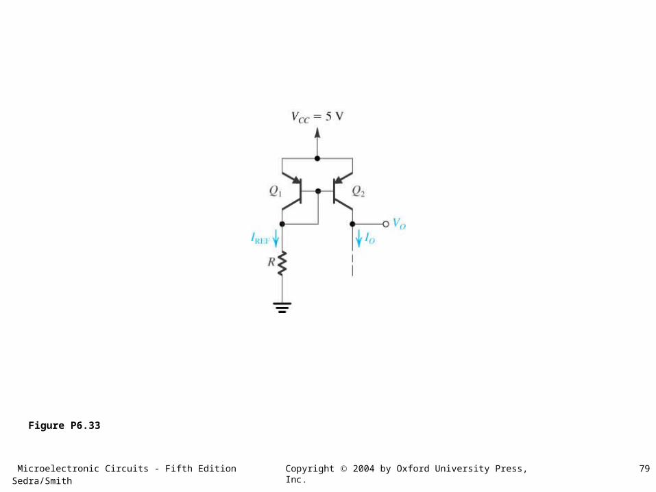
Figure P6.33
Microelectronic Circuits - Fifth Edition Sedra/Smith 80Copyright 2004 by Oxford University Press, Inc.
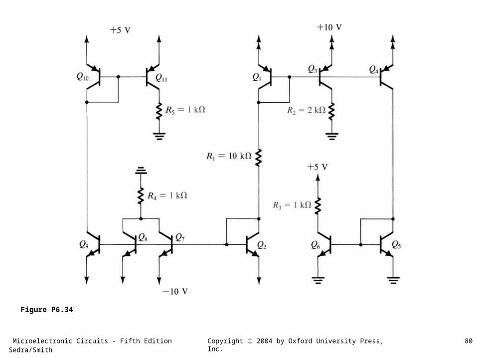
Figure P6.34
Microelectronic Circuits - Fifth Edition Sedra/Smith 81Copyright 2004 by Oxford University Press, Inc.
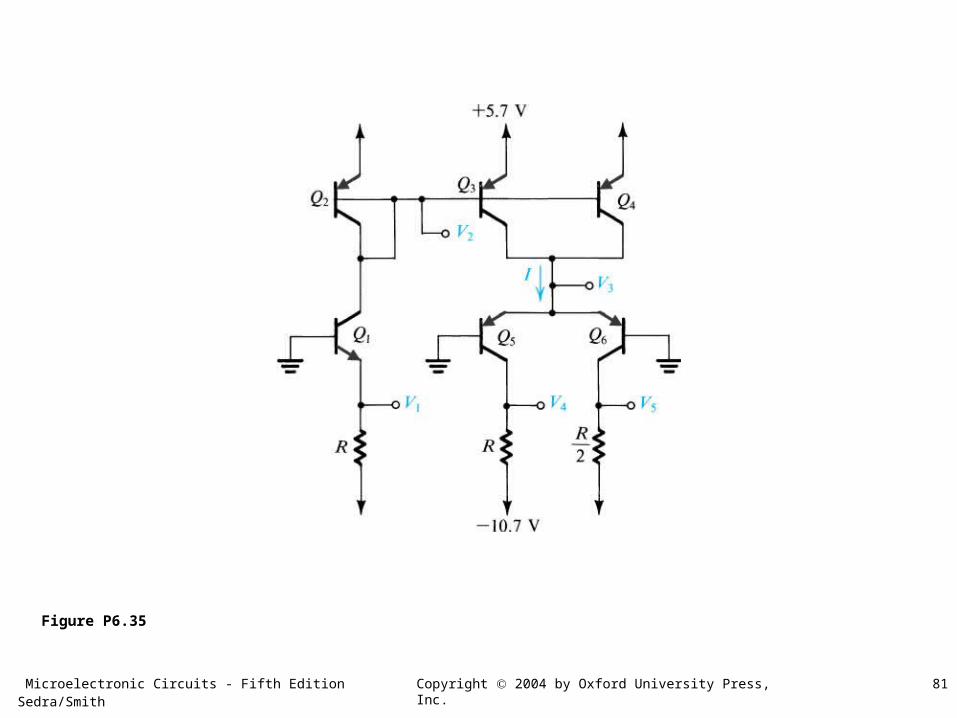
Figure P6.35
Microelectronic Circuits - Fifth Edition Sedra/Smith 82Copyright 2004 by Oxford University Press, Inc.
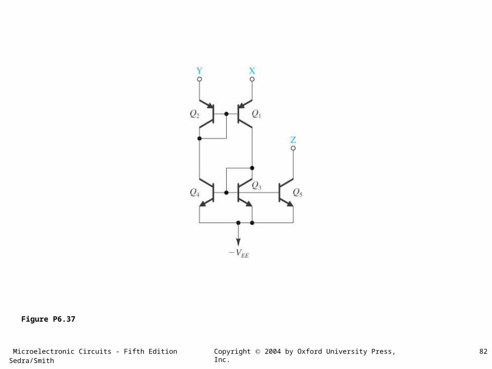
Figure P6.37
Microelectronic Circuits - Fifth Edition Sedra/Smith 83Copyright 2004 by Oxford University Press, Inc.
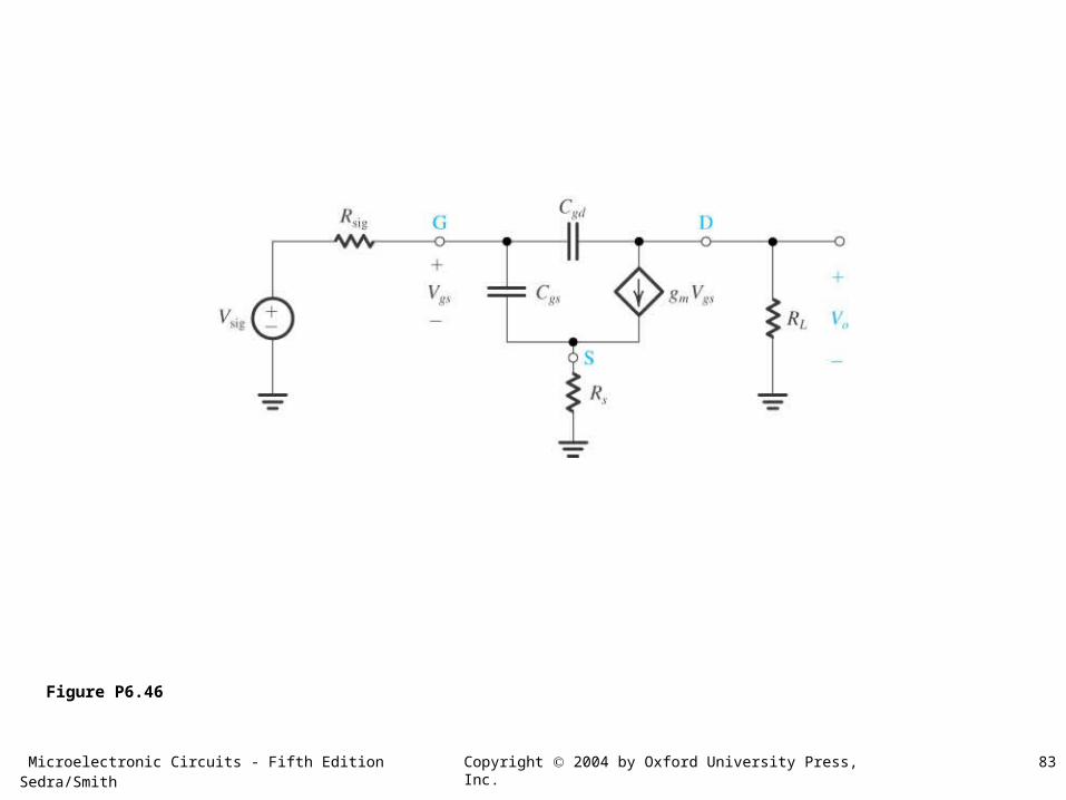
Figure P6.46
Microelectronic Circuits - Fifth Edition Sedra/Smith 84Copyright 2004 by Oxford University Press, Inc.
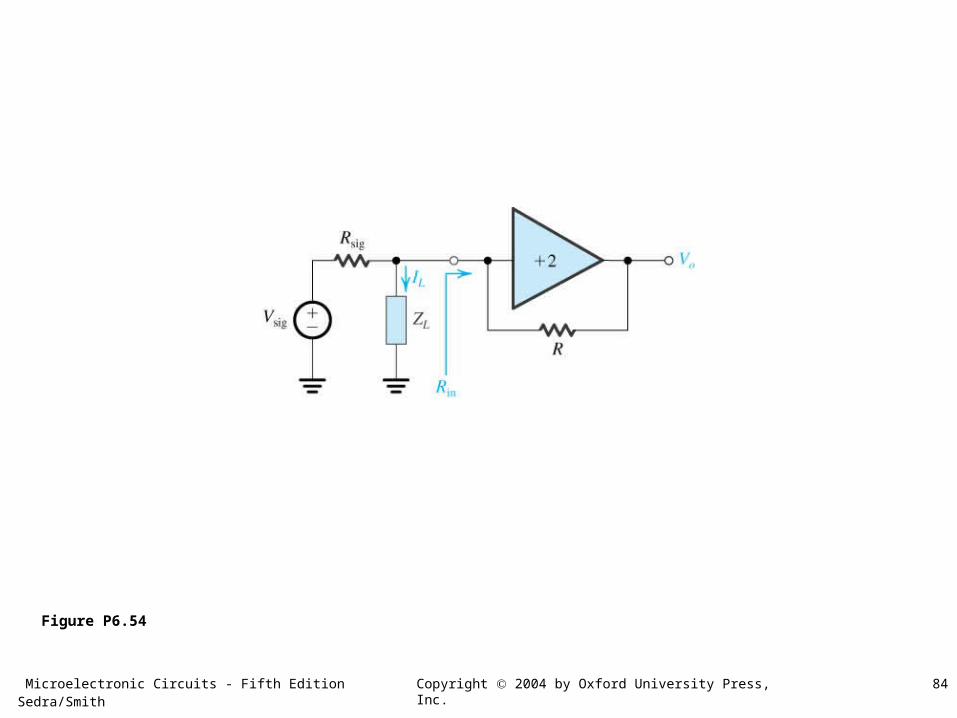
Figure P6.54
Microelectronic Circuits - Fifth Edition Sedra/Smith 85Copyright 2004 by Oxford University Press, Inc.
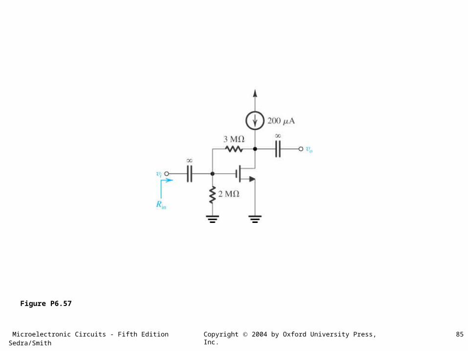
Figure P6.57
Microelectronic Circuits - Fifth Edition Sedra/Smith 86Copyright 2004 by Oxford University Press, Inc.
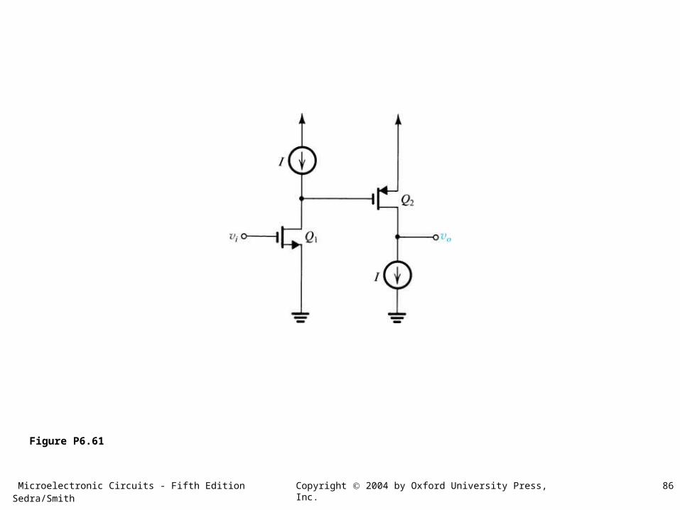
Figure P6.61
Microelectronic Circuits - Fifth Edition Sedra/Smith 87Copyright 2004 by Oxford University Press, Inc.
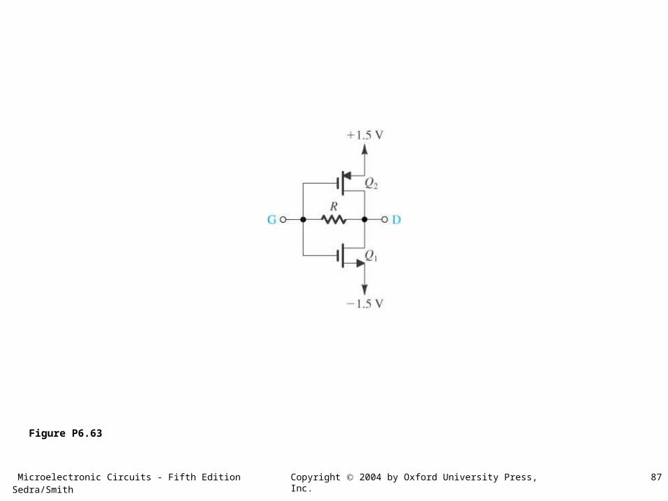
Figure P6.63
Microelectronic Circuits - Fifth Edition Sedra/Smith 88Copyright 2004 by Oxford University Press, Inc.
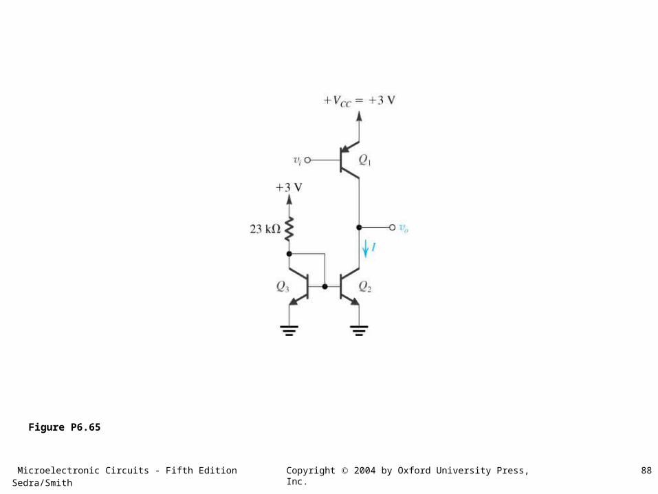
Figure P6.65
Microelectronic Circuits - Fifth Edition Sedra/Smith 89Copyright 2004 by Oxford University Press, Inc.
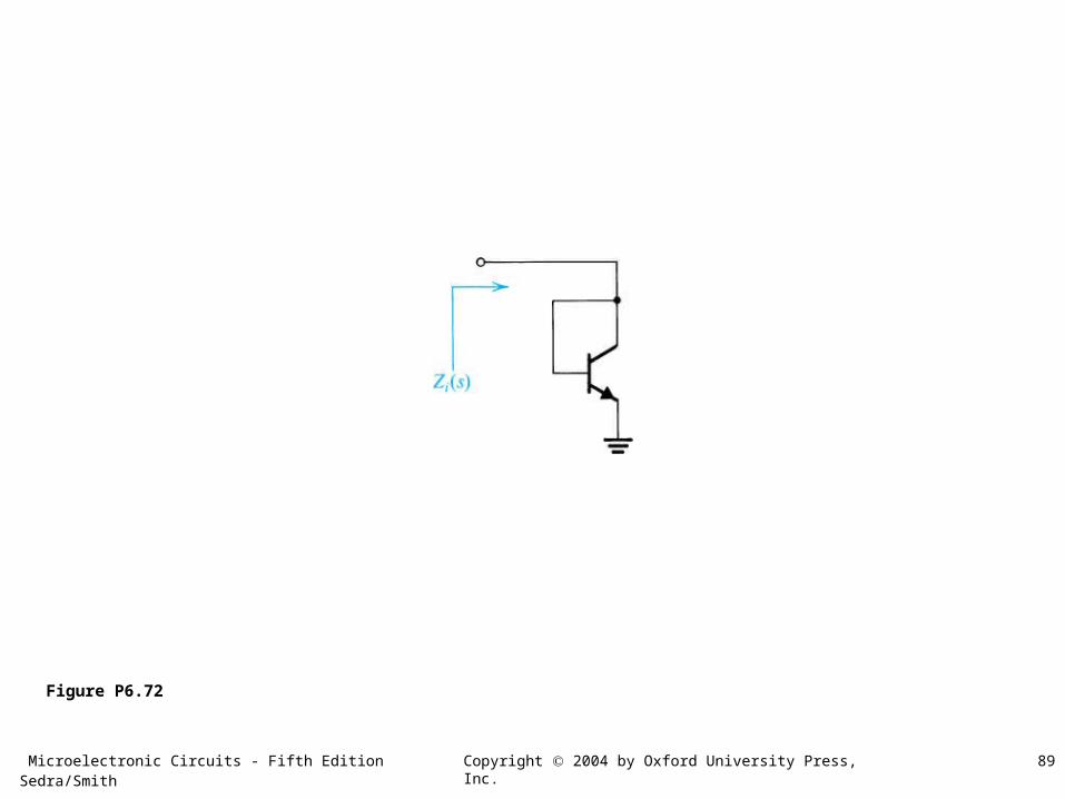
Figure P6.72
Microelectronic Circuits - Fifth Edition Sedra/Smith 90Copyright 2004 by Oxford University Press, Inc.
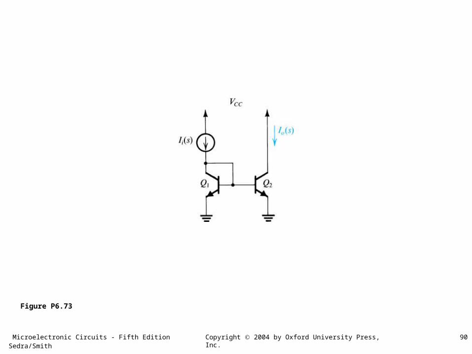
Figure P6.73
Microelectronic Circuits - Fifth Edition Sedra/Smith 91Copyright 2004 by Oxford University Press, Inc.
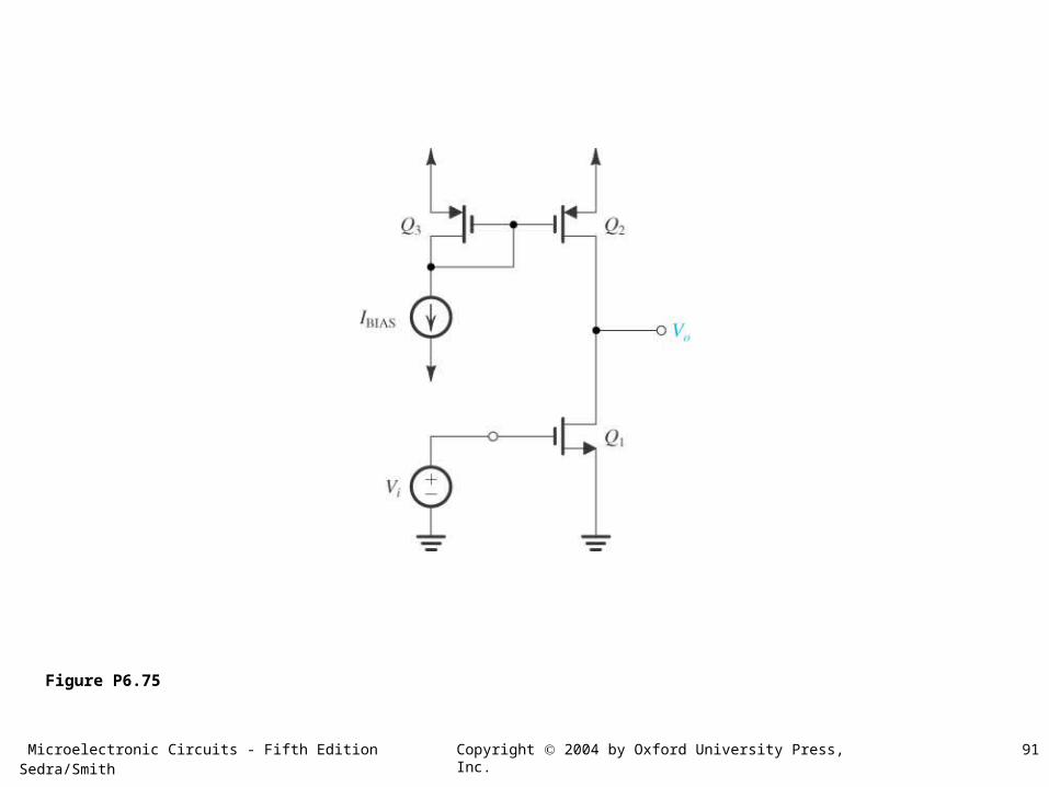
Figure P6.75
Microelectronic Circuits - Fifth Edition Sedra/Smith 92Copyright 2004 by Oxford University Press, Inc.
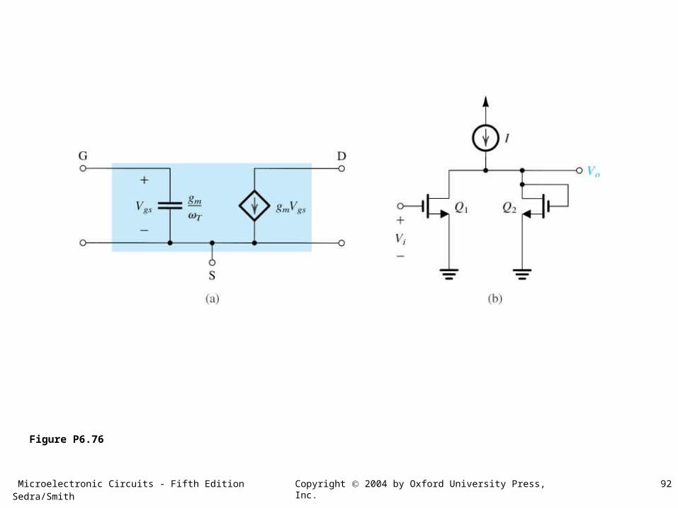
Figure P6.76
Microelectronic Circuits - Fifth Edition Sedra/Smith 93Copyright 2004 by Oxford University Press, Inc.
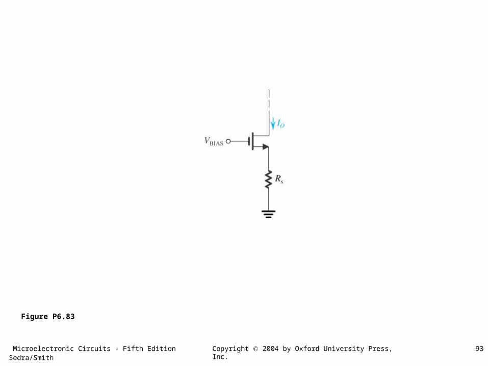
Figure P6.83
Microelectronic Circuits - Fifth Edition Sedra/Smith 94Copyright 2004 by Oxford University Press, Inc.
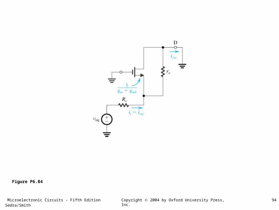
Figure P6.84
Microelectronic Circuits - Fifth Edition Sedra/Smith 95Copyright 2004 by Oxford University Press, Inc.
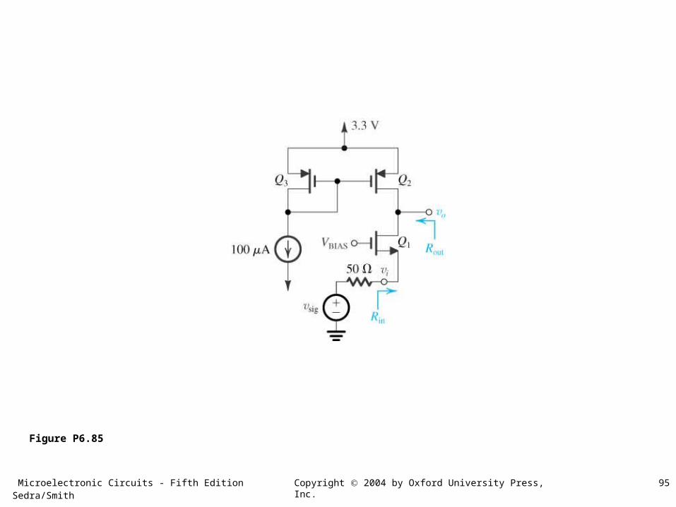
Figure P6.85
Microelectronic Circuits - Fifth Edition Sedra/Smith 96Copyright 2004 by Oxford University Press, Inc.
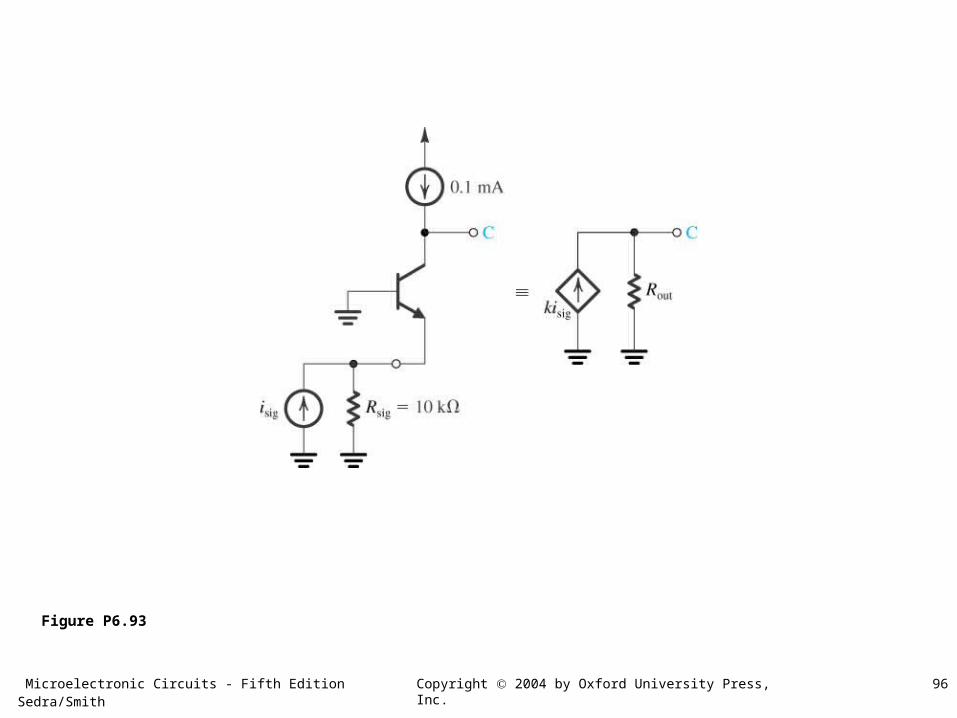
Figure P6.93
Microelectronic Circuits - Fifth Edition Sedra/Smith 97Copyright 2004 by Oxford University Press, Inc.
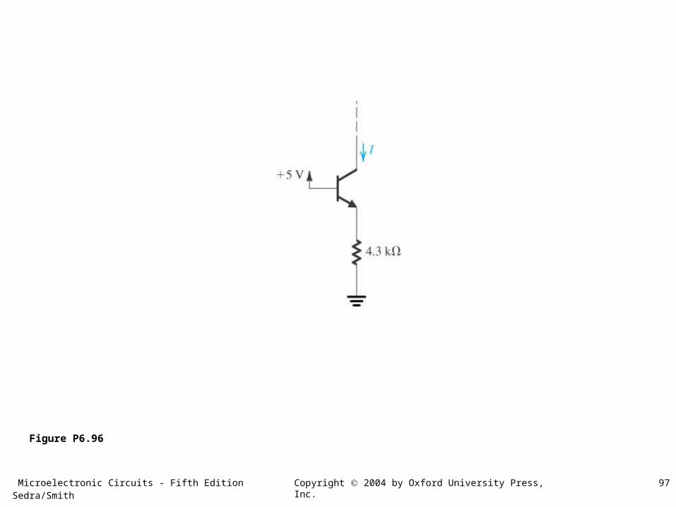
Figure P6.96
Microelectronic Circuits - Fifth Edition Sedra/Smith 98Copyright 2004 by Oxford University Press, Inc.
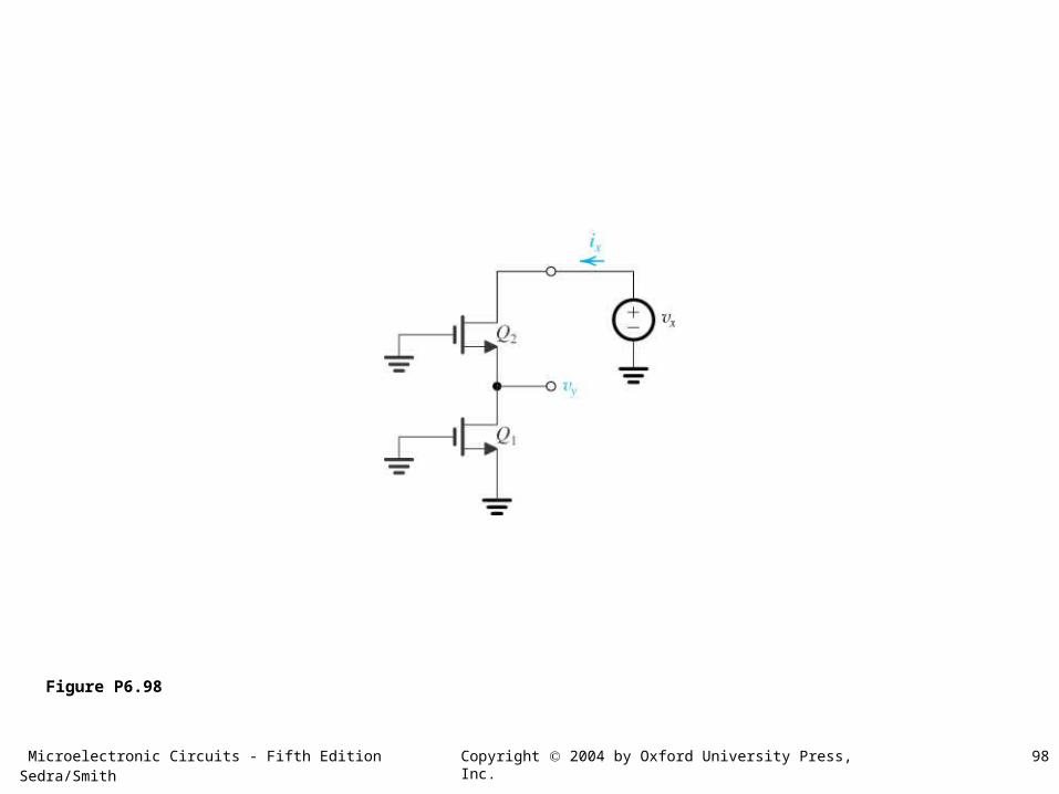
Figure P6.98
Microelectronic Circuits - Fifth Edition Sedra/Smith 99Copyright 2004 by Oxford University Press, Inc.
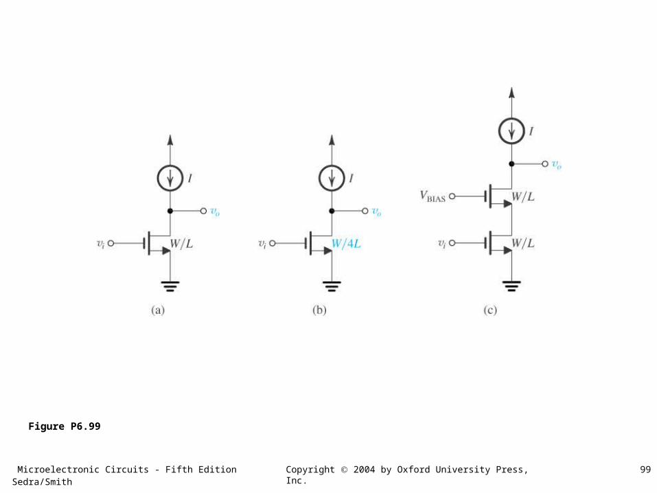
Figure P6.99
Microelectronic Circuits - Fifth Edition Sedra/Smith 100Copyright 2004 by Oxford University Press, Inc.
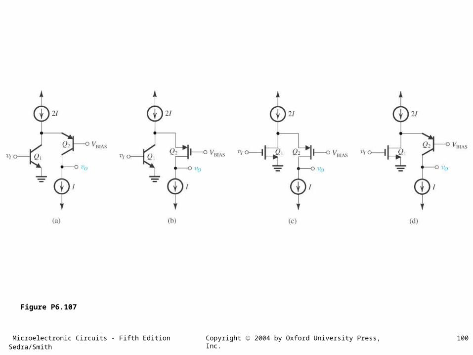
Figure P6.107
Microelectronic Circuits - Fifth Edition Sedra/Smith 101Copyright 2004 by Oxford University Press, Inc.
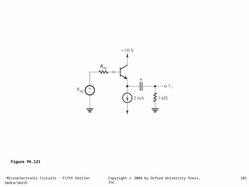
Figure P6.121
Microelectronic Circuits - Fifth Edition Sedra/Smith 102Copyright 2004 by Oxford University Press, Inc.
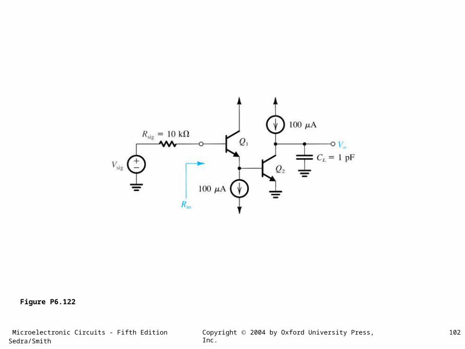
Figure P6.122
Microelectronic Circuits - Fifth Edition Sedra/Smith 103Copyright 2004 by Oxford University Press, Inc.
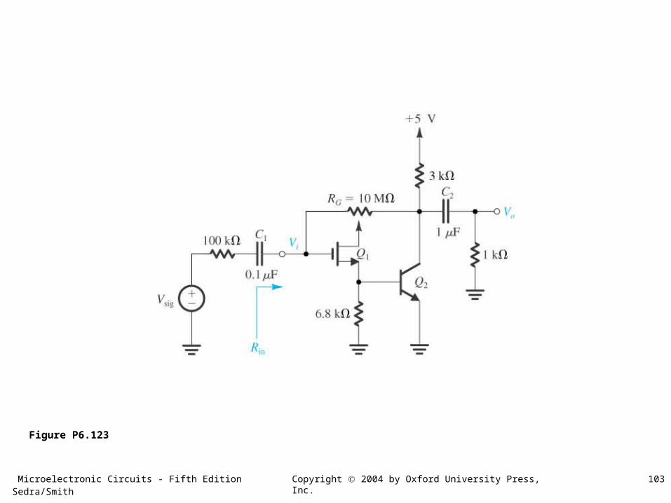
Figure P6.123
Microelectronic Circuits - Fifth Edition Sedra/Smith 104Copyright 2004 by Oxford University Press, Inc.
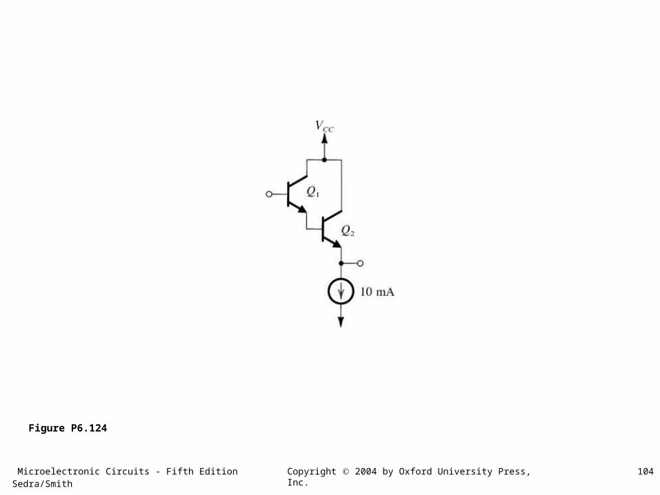
Figure P6.124
Microelectronic Circuits - Fifth Edition Sedra/Smith 105Copyright 2004 by Oxford University Press, Inc.
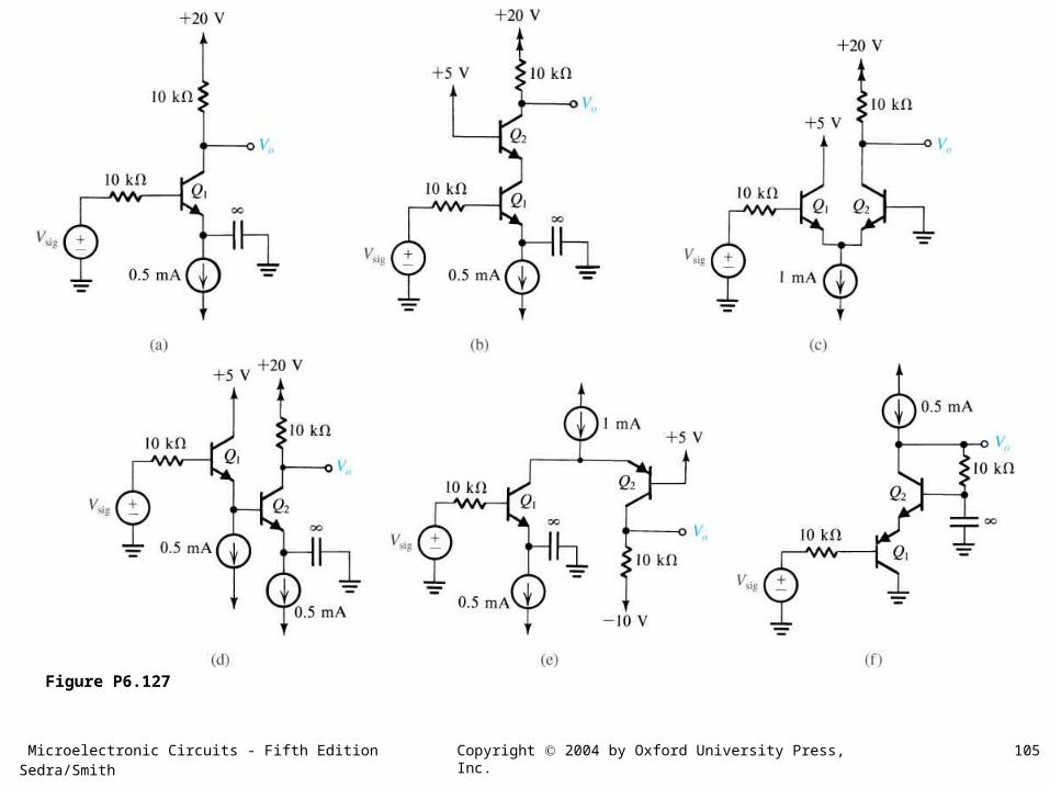
Figure P6.127
Microelectronic Circuits - Fifth Edition Sedra/Smith 106Copyright 2004 by Oxford University Press, Inc.
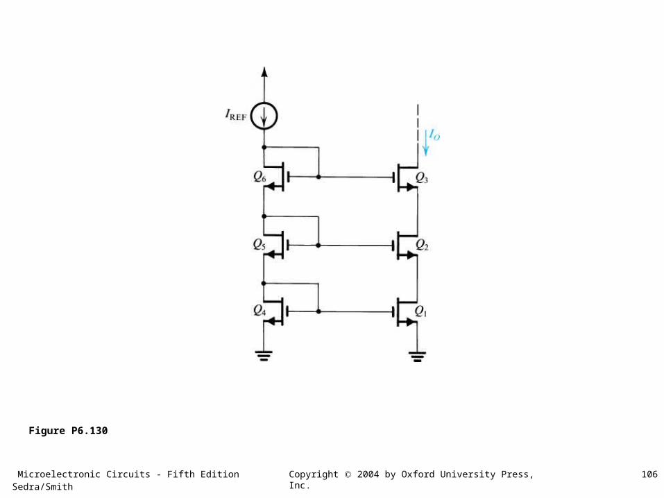
Figure P6.130
Microelectronic Circuits - Fifth Edition Sedra/Smith 107Copyright 2004 by Oxford University Press, Inc.
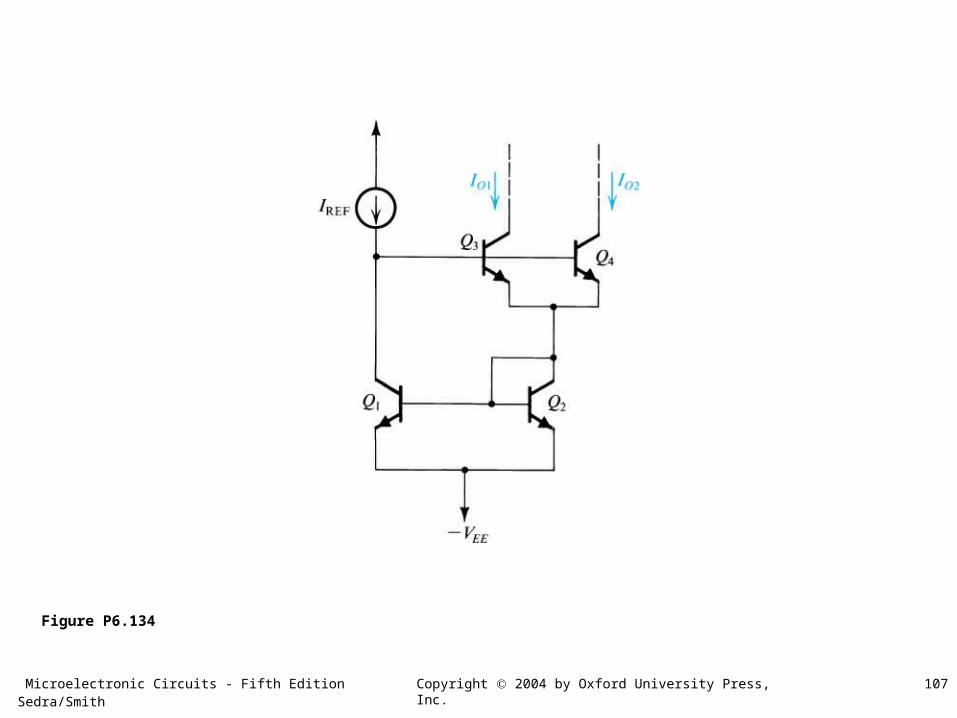
Figure P6.134
Microelectronic Circuits - Fifth Edition Sedra/Smith 108Copyright 2004 by Oxford University Press, Inc.
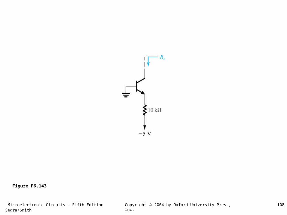
Figure P6.143
Microelectronic Circuits - Fifth Edition Sedra/Smith 109Copyright 2004 by Oxford University Press, Inc.
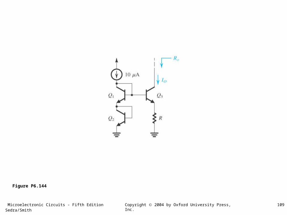
Figure P6.144
Microelectronic Circuits - Fifth Edition Sedra/Smith 110Copyright 2004 by Oxford University Press, Inc.
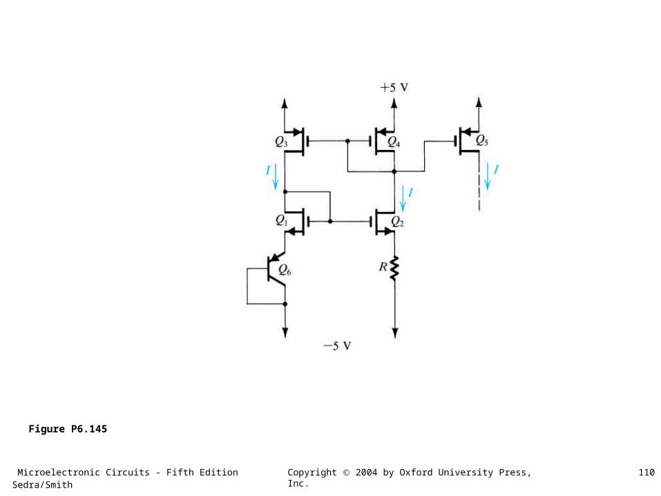
Figure P6.145