Embed Size (px)
Citation preview
^1 SOFTWARE REFERENCE MANUAL
^2 Pewin32 PRO
^3 PMAC Executive Software for Windows
^4 3A0-09WPRO-xSx1
Single S21314 L
ource Machine Control assen Street Chatsworth
^5 October 12, 2004
Power // Flexibility // Ease of Use , CA 91311 // Tel. (818) 998-2095 Fax. (818) 998-7807 // www.deltatau.com

Copyright Information © 2003 Delta Tau Data Systems, Inc. All rights reserved.
This document is furnished for the customers of Delta Tau Data Systems, Inc. Other uses are unauthorized without written permission of Delta Tau Data Systems, Inc. Information contained in this manual may be updated from time-to-time due to product improvements, etc., and may not conform in every respect to former issues.
To report errors or inconsistencies, call or email:
Delta Tau Data Systems, Inc. Technical Support Phone: (818) 717-5656 Fax: (818) 998-7807 Email: [email protected] Website: http://www.deltatau.com
Operating Conditions All Delta Tau Data Systems, Inc. motion controller products, accessories, and amplifiers contain static sensitive components that can be damaged by incorrect handling. When installing or handling Delta Tau Data Systems, Inc. products, avoid contact with highly insulated materials. Only qualified personnel should be allowed to handle this equipment.
In the case of industrial applications, we expect our products to be protected from hazardous or conductive materials and/or environments that could cause harm to the controller by damaging components or causing electrical shorts. When our products are used in an industrial environment, install them into an industrial electrical cabinet or industrial PC to protect them from excessive or corrosive moisture, abnormal ambient temperatures, and conductive materials. If Delta Tau Data Systems, Inc. products are directly exposed to hazardous or conductive materials and/or environments, we cannot guarantee their operation.
PEWIN32 PRO Software Reference Manual
Table of Contents OVERVIEW .......................................................................................................................................................................1
Introduction ......................................................................................................................................................................1 Features ............................................................................................................................................................................1 Hardware and Software Requirements .............................................................................................................................2
GETTING STARTED........................................................................................................................................................3 Installing Pewin32PRO ....................................................................................................................................................3 Help Features....................................................................................................................................................................3 Technical Support ............................................................................................................................................................3
MENU OVERVIEW ..........................................................................................................................................................5 How Menus Work ............................................................................................................................................................5 File Menu .........................................................................................................................................................................6 Configure Menu ...............................................................................................................................................................7 View Menu.......................................................................................................................................................................8 Resource Manager Menu..................................................................................................................................................8 Backup Menu ...................................................................................................................................................................9 Setup Menu ......................................................................................................................................................................9 Tools Menu ......................................................................................................................................................................9 Window Menu................................................................................................................................................................10 Help Menu......................................................................................................................................................................10
BASIC CONCEPTS .........................................................................................................................................................11 Workspace Management ................................................................................................................................................11 Project Management.......................................................................................................................................................12 Message Window ...........................................................................................................................................................12 Uploading Programs from PMAC..................................................................................................................................13 Uploading PMAC Variables ..........................................................................................................................................13 Downloading Files to PMAC.........................................................................................................................................14
Using Macros in the Editor .......................................................................................................................................14 Download Options .....................................................................................................................................................16
Terminal .........................................................................................................................................................................17 Changing the Appearance of the Terminal ................................................................................................................17 Selecting DPRAM ASCII Communication .................................................................................................................18 Enable View Interrupts ..............................................................................................................................................18
Position Window............................................................................................................................................................18 Position Menu............................................................................................................................................................19 Units and Scales ........................................................................................................................................................19
Watch Window...............................................................................................................................................................20 Watch Menu...............................................................................................................................................................21 Adding Entries to the Watch Window ........................................................................................................................22 Adding and Editing Macro Definitions......................................................................................................................22 Editing Macros ..........................................................................................................................................................23 Add Multiple Variables..............................................................................................................................................23 Editing Watch Entries................................................................................................................................................24
DPR Viewer ...................................................................................................................................................................24 Status Screens.................................................................................................................................................................25
Connector Status........................................................................................................................................................25 Motor Status ..............................................................................................................................................................27 Coordinate Systems Status.........................................................................................................................................27 Global Status .............................................................................................................................................................28 Motor Setup Summary ...............................................................................................................................................28 Motion Programs/PLCs Status ..................................................................................................................................29 PLCC Program Status ...............................................................................................................................................29
PMAC CONFIGURATION ............................................................................................................................................31
Table of Contents i
PEWIN32 PRO Software Reference Manual
I-Variables......................................................................................................................................................................31 I-Variables by Category.............................................................................................................................................31 I-Variables by Number ..............................................................................................................................................34 I-Variables MACRO ..................................................................................................................................................35
M, P and Q-Variables.....................................................................................................................................................35 Coordinate Systems........................................................................................................................................................36
Coordinate System to Modify-Monitor ......................................................................................................................36 Current Axis Definitions ............................................................................................................................................36 Edit ............................................................................................................................................................................36 Remove.......................................................................................................................................................................36 Available Motors .......................................................................................................................................................36 Add.............................................................................................................................................................................37 View all Coordinate Systems .....................................................................................................................................37 Done ..........................................................................................................................................................................37
Encoder Conversion Table .............................................................................................................................................37 Entry Number ............................................................................................................................................................38 Entry, Source and Processed Data Addresses ...........................................................................................................38 Conversion Type ........................................................................................................................................................38 View All Entries of Table ...........................................................................................................................................39 Download Entry.........................................................................................................................................................39 Done ..........................................................................................................................................................................39 Inc with Inv-T Ext ......................................................................................................................................................39 A-D Register ..............................................................................................................................................................39 Parallel with and without Filter ................................................................................................................................39 Filter-Max Change ....................................................................................................................................................40 Time Base ..................................................................................................................................................................40 Triggered Time Base..................................................................................................................................................40 Inc with Parallel Ext ..................................................................................................................................................40 Inc without Parallel Ext.............................................................................................................................................40 Summing Table Entries to Another ............................................................................................................................40 Bits Enabled Mask .....................................................................................................................................................41 Max Change...............................................................................................................................................................41 Conversion Shifting of Parallel Data ........................................................................................................................41
Encoder Conversion Table MACRO..............................................................................................................................41 ADVANCED FEATURES ...............................................................................................................................................43
EditorPro ........................................................................................................................................................................43 Introduction ...............................................................................................................................................................43 Syntax Highlighting ...................................................................................................................................................44 Auto Indenting ...........................................................................................................................................................44 Auto Correction .........................................................................................................................................................45 Popup Debugger Window..........................................................................................................................................45 Error Tracing ............................................................................................................................................................47 Editor Menu...............................................................................................................................................................48 Setup Window ............................................................................................................................................................50
Debugger ........................................................................................................................................................................52 Introduction ...............................................................................................................................................................52 How to Use the Debugger..........................................................................................................................................52 Important Notes .........................................................................................................................................................56
Resource Manager..........................................................................................................................................................57 Introduction ...............................................................................................................................................................57 How to Use Resource Manager .................................................................................................................................57 Active Project ............................................................................................................................................................60 Using Resource Manager in the Terminal Window...................................................................................................60 Using Resource Manager in the EditorPRO..............................................................................................................61 Important Notes .........................................................................................................................................................62
ii Table of Contents
PEWIN32 PRO Software Reference Manual
TUNING, DATA GATHERING, PLOTTING AND CONFIGURATION .................................................................63 External Tools ................................................................................................................................................................63
CONFIGURATION FILES.............................................................................................................................................65 Backup and Restore PMAC Configuration Files ...........................................................................................................65
Upload Configuration................................................................................................................................................65 Restore Configuration ...............................................................................................................................................65 Verify PMAC Configuration ......................................................................................................................................65
PEWIN32PRO GENERAL SETUP AND OPTIONS ...................................................................................................67 Setup Menu ....................................................................................................................................................................67
PEWIN32PRO HELP ......................................................................................................................................................69 Pewin32Pro Manual .......................................................................................................................................................69 Driver Installation Notes ................................................................................................................................................69 Why am I Not Moving?..................................................................................................................................................69 Why is my Program Not Running? ................................................................................................................................69
APPENDIX A - UNDERSTANDING PMAC’S WATCHDOG TIMER.....................................................................71 PMAC’s Watchdog Timer..............................................................................................................................................71 How the Watchdog Timer Works...................................................................................................................................71 What to Look for When the Timer Trips........................................................................................................................72
APPENDIX B - BUG REPORT AND FEATURE REQUEST PROCEDURE...........................................................75 Known Bugs...................................................................................................................................................................75 Wish List ........................................................................................................................................................................75
INDEX ...............................................................................................................................................................................77
Table of Contents iii

PEWIN32 PRO Software Reference Manual
iv Table of Contents
PEWIN32 PRO Software Reference Manual
OVERVIEW Introduction Welcome to Pewin32PRO, Delta Tau’s PMAC Executive software for Microsoft Windows. This software enables you to configure, control and trouble-shoot your PMAC (Programmable Multi-Axis Controller). At its core, Pewin32Pro provides a terminal, a text editor for editing Motion/PLC programs and a workspace environment. Additionally, there is a suite of tools for configuring and working with PMAC and its accessories. Pewin32PRO is a development tool for creating and managing specific PMAC implementations.
This document details all the features of Pewin32Pro, and explains how to use Pewin32PRO to communicate and control your PMAC motion control card. Companion applications such as Plotting, Tuning and Setup have separate documentation. Knowledge of the basic use of the Windows operating system is assumed.
Note:
Pewin32Pro uses the latest driver from Delta Tau, PComm32 Pro, which works most efficiently with firmware that supports I63 and I64 (Ctrl-X echo, and Internal Response Tag Enable). Firmware version 1.16F and beyond for non-Turbo and 1.931 and beyond for Turbo PMACs will support these I-Variables.
Features This version of the PMAC Executive software is based on the previous versions but has been enhanced in many ways. In this version Pewin32Pro has:
• •
• • • •
• •
• • • • • •
Multi-threading of Pewin32PRO real-time display windows. Enhanced graphing in PmacPlotPRO.
A thread safe communications driver makes this version also compatible with the 32-bit version of "NC for Windows" software (and any application using PComm32PRO or PTalkPRO, Accessory 9PNPRO or 9PTPRO, respectively).
Pewin32PRO provides basic tools to configure, control and diagnose PMACs. Here is a partial list of Pewin32PRO’s features and capabilities:
Workspace support Project management A terminal window A real-time color editor with many options. Features include error tracking during downloads, color options for different commands and compatibility with standard PMAC code. Advanced features of the editor include
A real-time PLC debugger. See editor section for detailed description Managing the code syntax and applying appropriate indenting and margins
Easy handling of PMAC’s thousands of I, P, Q and M-variables, including macro support. Watch window for real-time system information and debugging. Motor, Coordinate System and Global status windows that display PMAC’s status bits in real-time. Position Window for displaying the position, velocity and following error of all motors on the system. Diagnostic routines for debugging motors and motion programs. Different programs (including motion programs, PLCs, PLCCs, Rotary buffers, Inverse and forward kinematics) status and upload screens.
Overview 1
PEWIN32 PRO Software Reference Manual
• • • •
Resource manager responsible for keeping track of all MACRO definitions for an active project. Real-time status display of all PMAC’s connectors. The ability to talk to multiple PMACs on a single computer. And many more.
Pewin32PRO has many tools to help both the novice and the advanced PMAC user get the most out of their PMACs.
Hardware and Software Requirements The PMAC Executive for Windows software will run on any computer capable of running Windows 98/ME or 2000 (TM) (266 MHz Pentium MMX and up recommended). Of course, the faster the computer, the better. In addition, you will need the following:
• • •
•
Microsoft Windows 98/ME/2000 or Windows XP loaded on your computer. At least 50 MB of free disk space and 64 MB of RAM. A free serial communications port, or USB port, or Ethernet port, or PCI-BUS slot, or ISA-BUS slot to talk to PMAC for on-line processing. Any monitor with VGA resolution (800x600 with at least 256 colors suggested but 640x480 works fine).
2 Overview
PEWIN32 PRO Software Reference Manual
GETTING STARTED Installing Pewin32PRO Before installing Pewin32PRO, read the license agreement included in this manual (behind title page), and make a backup copy of the installation disks. Then install Pewin32PRO according to the instructions in the PComm32Pro Installation Procedures User Manual.
Help Features Context sensitive help is available. Simply press F1 to launch the help system.
Why Am I Not Moving? and Why Is My Program Not Running? are the two diagnostic functions in the Help menu. These are only available if you are communicating with a PMAC. Probably, these will save you many hours of searching and frustration in tracking down problems associated with running a motor or part program, especially if you are new to PMAC. You may run into a condition in which a motor simply will not run, even though you are sure that all the parameters have been set properly. These functions will look at your configuration and cite possible (warnings) or definite (faults) causes of problems preventing you from running your motor(s) / program(s). “Why am I not moving?” requires that you specify a motor to analyze while “Why is my program not running?” requires that you specify a coordinate system to analyze.
The About box will give you detailed information about the version of the software you are running.
Technical Support Delta Tau is happy to respond to any questions or concerns you have regarding the Windows Executive. By far, you'll get the quickest response if you send your queries to the following e-mail address: [email protected]. Of course, please do check out our Web site at www.deltatau.com.
You can call Delta Tau Monday through Friday from 9:00 AM to 4:30 PM PST or FAX us your request or problem, and we will deal with it the next business day.
West Coast East Coast
Voice: (818) 998-2095 Voice: (804) 795-4288
Delta Tau Data Systems, Inc. 21314 Lassen Street Chatsworth CA, 91311
FAX: (818) 998-7807 FAX: (804) 795-4996
Getting Started 3

PEWIN32 PRO Software Reference Manual
4 Getting Started
PEWIN32 PRO Software Reference Manual
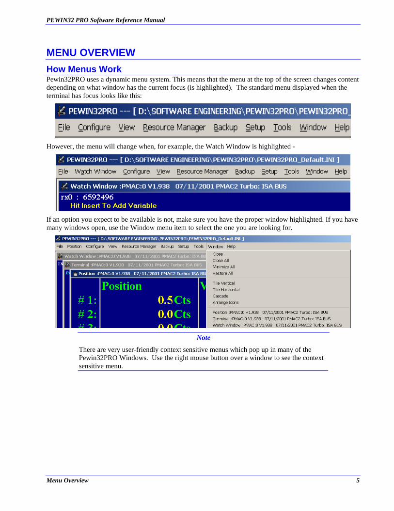
MENU OVERVIEW How Menus Work Pewin32PRO uses a dynamic menu system. This means that the menu at the top of the screen changes content depending on what window has the current focus (is highlighted). The standard menu displayed when the terminal has focus looks like this:
However, the menu will change when, for example, the Watch Window is highlighted -
If an option you expect to be available is not, make sure you have the proper window highlighted. If you have many windows open, use the Window menu item to select the one you are looking for.
Note
There are very user-friendly context sensitive menus which pop up in many of the Pewin32PRO Windows. Use the right mouse button over a window to see the context sensitive menu.
Menu Overview 5

PEWIN32 PRO Software Reference Manual
File Menu The File menu handles several things:
1. Opening an existing or creating a new text file. 2. Management of workspaces 3. Uploading and downloading PMAC related text files.
• • • •
NEW FILE – Opens the editor, if not already open, and creates a new text file ready for editing. OPEN FILE – Opens the editor, if not already open, and loads the selected file. UPLOAD MOTION PROGRAM – Uploads the specified PMC program into an editor window. NEW WORKSPACE – First saves the current workspace, provided the General Setup and Options has been set to do so (See Setup | General Setup and Options), closes all open windows, and asks you for the name of your new workspace. Pewin32PRO will load the last workspace opened at the time of exiting the application.
•
• •
OPEN WORKSPACE – Closes the current workspace, if any is open, and opens the selected workspace file. SAVE WORKSPACE – Saves the workspace whenever this menu item is selected. SAVE WORKSPACE AS – Renames the active workspace, but first saves the active workspace provided the General Setup and Options has been set to do so (See Setup | General Setup and Options)
• CLOSE WORKSPACE – Closes all open windows, and saves the workspace, provided the General Setup and Options has been set to do so (See Setup | General Setup and Options).
• •
•
SHOW PROJECT MANAGER – Hides or shows the Project Manager. UPLOAD PROGRAM(S) – Uploads the listed motion and PLC programs into a file and then open that file in the editor window. UPLOAD VARIABLES – Allows uploading a range of I, P, Q or M variables into an editor window.
6 Menu Overview
PEWIN32 PRO Software Reference Manual
• •
DOWNLOAD FILE – Allows downloading any file with valid PMAC commands. EXIT – Closes the program.
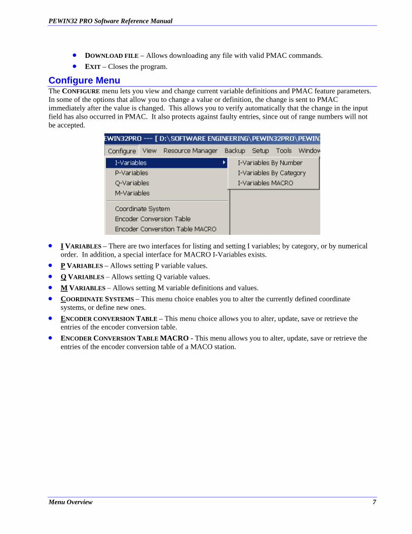
Configure Menu The CONFIGURE menu lets you view and change current variable definitions and PMAC feature parameters. In some of the options that allow you to change a value or definition, the change is sent to PMAC immediately after the value is changed. This allows you to verify automatically that the change in the input field has also occurred in PMAC. It also protects against faulty entries, since out of range numbers will not be accepted.
• I VARIABLES – There are two interfaces for listing and setting I variables; by category, or by numerical order. In addition, a special interface for MACRO I-Variables exists.
• P VARIABLES – Allows setting P variable values. • Q VARIABLES – Allows setting Q variable values. • M VARIABLES – Allows setting M variable definitions and values. • COORDINATE SYSTEMS – This menu choice enables you to alter the currently defined coordinate
systems, or define new ones. • ENCODER CONVERSION TABLE – This menu choice allows you to alter, update, save or retrieve the
entries of the encoder conversion table. • ENCODER CONVERSION TABLE MACRO - This menu allows you to alter, update, save or retrieve the
entries of the encoder conversion table of a MACO station.
Menu Overview 7
PEWIN32 PRO Software Reference Manual
View Menu
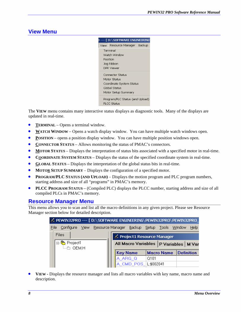
The VIEW menu contains many interactive status displays as diagnostic tools. Many of the displays are updated in real-time.
• TERMINAL – Opens a terminal window. • WATCH WINDOW – Opens a watch display window. You can have multiple watch windows open. • POSITION – opens a position display window. You can have multiple position windows open. • CONNECTOR STATUS – Allows monitoring the status of PMAC’s connectors. • MOTOR STATUS – Displays the interpretation of status bits associated with a specified motor in real-time. • COORDINATE SYSTEM STATUS – Displays the status of the specified coordinate system in real-time. • GLOBAL STATUS – Displays the interpretation of the global status bits in real-time. • MOTOR SETUP SUMMARY – Displays the configuration of a specified motor. •
•
PROGRAM/PLC STATUS (AND UPLOAD) – Displays the motion program and PLC program numbers, starting address and size of all “programs” in PMAC’s memory. PLCC PROGRAM STATUS – (Compiled PLC) displays the PLCC number, starting address and size of all compiled PLCs in PMAC’s memory.
Resource Manager Menu This menu allows you to scan and list all the macro definitions in any given project. Please see Resource Manager section below for detailed description.
• VIEW - Displays the resource manager and lists all macro variables with key name, macro name and description.
8 Menu Overview
PEWIN32 PRO Software Reference Manual
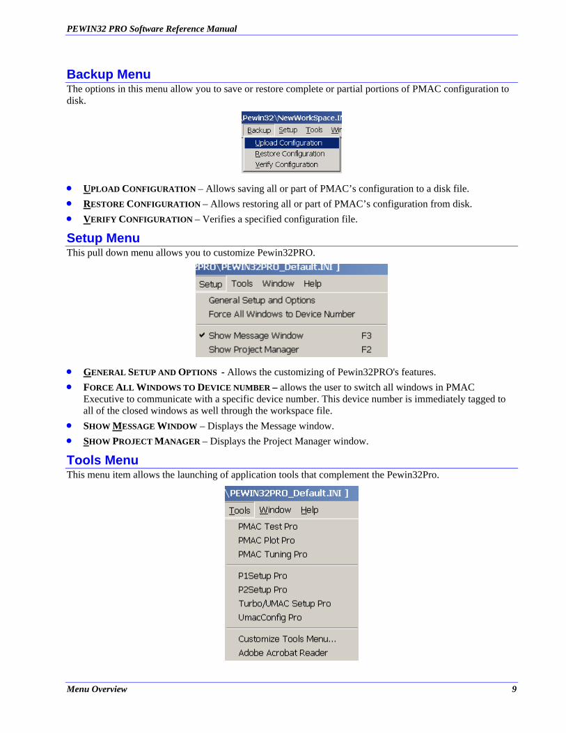
Backup Menu The options in this menu allow you to save or restore complete or partial portions of PMAC configuration to disk.
• UPLOAD CONFIGURATION – Allows saving all or part of PMAC’s configuration to a disk file. • RESTORE CONFIGURATION – Allows restoring all or part of PMAC’s configuration from disk. • VERIFY CONFIGURATION – Verifies a specified configuration file.
Setup Menu This pull down menu allows you to customize Pewin32PRO.
• GENERAL SETUP AND OPTIONS - Allows the customizing of Pewin32PRO's features. •
•
FORCE ALL WINDOWS TO DEVICE NUMBER – allows the user to switch all windows in PMAC Executive to communicate with a specific device number. This device number is immediately tagged to all of the closed windows as well through the workspace file. SHOW MESSAGE WINDOW – Displays the Message window.
• SHOW PROJECT MANAGER – Displays the Project Manager window.
Tools Menu This menu item allows the launching of application tools that complement the Pewin32Pro.
Menu Overview 9

PEWIN32 PRO Software Reference Manual
•
•
PMAC TEST PRO - Launches PmacTest program. PmacTest is now installed with Pewin32PRO Executive. PMAC PLOT PRO - Launches PmacPlot program (if it is installed).
• PMAC TUNING PRO - Launches Pmac Tuning program (if it is installed). • P1 SETUP AND TUNING PRO - Launches the PMAC1 setup program (if it is installed). • P2 SETUP AND TUNING PRO - Launches the PMAC2 setup program (if it is installed). • TURBO/UMAC SETUP PRO - Launches the Turbo Setup program (if it is installed). • •
UMAC CONFIG PRO - Launches the UMAC Configuration Setup program (if it is installed). CUSTOMIZE TOOLS MENU – Allows adding third party applications in the tool menu. These applications then can be launched from the tools menu. These applications are listed after the customize tools menu.
Window Menu This menu is for managing the position and arrangement of any windows currently displayed. It is dynamically updated to allow easy selection of a specific window. Further, it shows all of PMAC Executive windows and on selecting a window bring it to the front.
Help Menu The HELP menu options allow you to retrieve on-line information about PMAC, the Executive program, and the various help functions. You also have access to the two diagnostic routines provided by Pewin32PRO.
• • •
•
CONTENTS – Displays this manual's content in the help file format. WHY AM I NOT MOVING ? – A diagnostic routine to help determine why a motor is not responding. WHY IS MY PROGRAM NOT RUNNING ? – A diagnostic routine to help determine why a program is not running. ABOUT – displays information about your version of Pewin32PRO, including the version number, the copyright, legal and licensing notices.
10 Menu Overview
PEWIN32 PRO Software Reference Manual
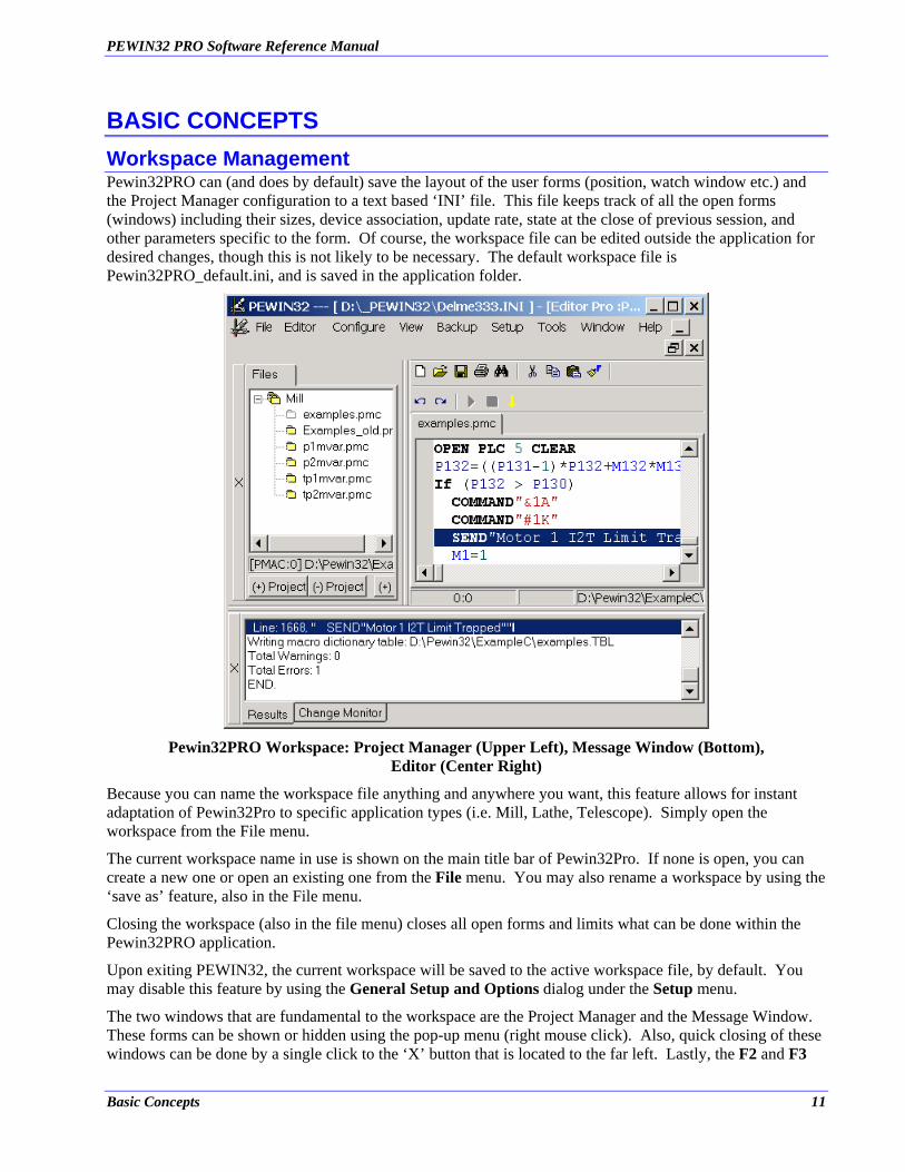
BASIC CONCEPTS Workspace Management Pewin32PRO can (and does by default) save the layout of the user forms (position, watch window etc.) and the Project Manager configuration to a text based ‘INI’ file. This file keeps track of all the open forms (windows) including their sizes, device association, update rate, state at the close of previous session, and other parameters specific to the form. Of course, the workspace file can be edited outside the application for desired changes, though this is not likely to be necessary. The default workspace file is Pewin32PRO_default.ini, and is saved in the application folder.
Pewin32PRO Workspace: Project Manager (Upper Left), Message Window (Bottom),
Editor (Center Right)
Because you can name the workspace file anything and anywhere you want, this feature allows for instant adaptation of Pewin32Pro to specific application types (i.e. Mill, Lathe, Telescope). Simply open the workspace from the File menu.
The current workspace name in use is shown on the main title bar of Pewin32Pro. If none is open, you can create a new one or open an existing one from the File menu. You may also rename a workspace by using the ‘save as’ feature, also in the File menu.
Closing the workspace (also in the file menu) closes all open forms and limits what can be done within the Pewin32PRO application.
Upon exiting PEWIN32, the current workspace will be saved to the active workspace file, by default. You may disable this feature by using the General Setup and Options dialog under the Setup menu.
The two windows that are fundamental to the workspace are the Project Manager and the Message Window. These forms can be shown or hidden using the pop-up menu (right mouse click). Also, quick closing of these windows can be done by a single click to the ‘X’ button that is located to the far left. Lastly, the F2 and F3
Basic Concepts 11
PEWIN32 PRO Software Reference Manual
open and close the Project Manager and Message Window, respectively. Usage of these windows is described next.
Project Management All applications involving PMAC require some customization. Typically, these customizations are held and organized in text files. The Project Manager facilitates the quick reference, organization and downloading of such files.
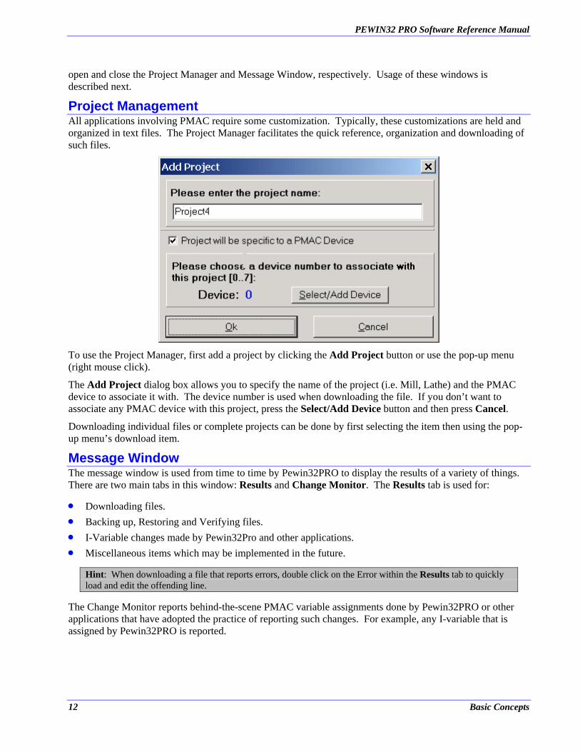
To use the Project Manager, first add a project by clicking the Add Project button or use the pop-up menu (right mouse click).
The Add Project dialog box allows you to specify the name of the project (i.e. Mill, Lathe) and the PMAC device to associate it with. The device number is used when downloading the file. If you don’t want to associate any PMAC device with this project, press the Select/Add Device button and then press Cancel.
Downloading individual files or complete projects can be done by first selecting the item then using the pop-up menu’s download item.
Message Window The message window is used from time to time by Pewin32PRO to display the results of a variety of things. There are two main tabs in this window: Results and Change Monitor. The Results tab is used for:
• • • •
Downloading files. Backing up, Restoring and Verifying files. I-Variable changes made by Pewin32Pro and other applications. Miscellaneous items which may be implemented in the future.
Hint: When downloading a file that reports errors, double click on the Error within the Results tab to quickly load and edit the offending line.
The Change Monitor reports behind-the-scene PMAC variable assignments done by Pewin32PRO or other applications that have adopted the practice of reporting such changes. For example, any I-variable that is assigned by Pewin32PRO is reported.
12 Basic Concepts
PEWIN32 PRO Software Reference Manual
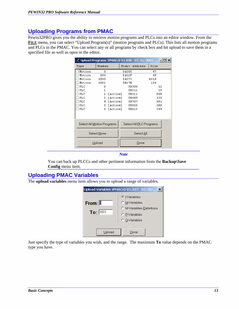
Uploading Programs from PMAC Pewin32PRO gives you the ability to retrieve motion programs and PLCs into an editor window. From the FILE menu, you can select “Upload Program(s)” (motion programs and PLCs). This lists all motion programs and PLCs in the PMAC. You can select any or all programs by check box and hit upload to save them in a specified file as well as open in the editor.
Note
You can back up PLCCs and other pertinent information from the Backup\Save Config menu item.
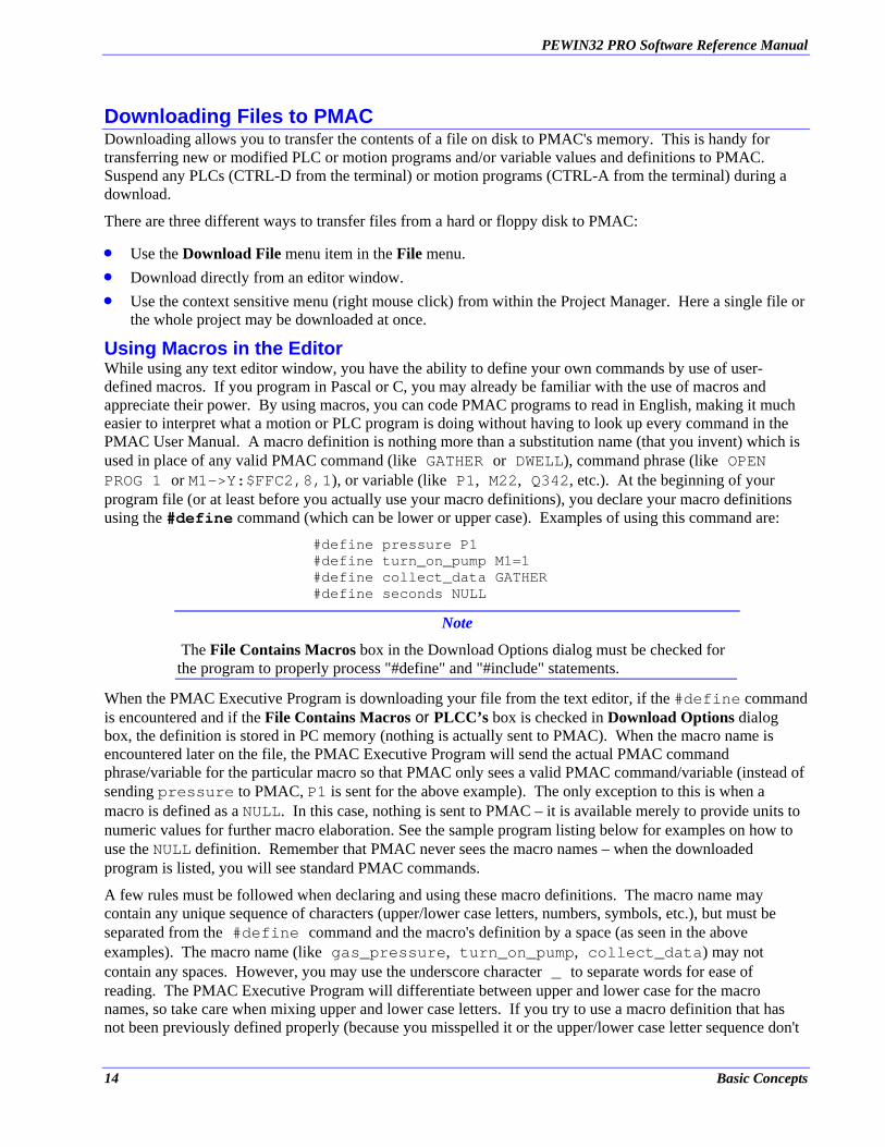
Uploading PMAC Variables The upload variables menu item allows you to upload a range of variables.
Just specify the type of variables you wish, and the range. The maximum To value depends on the PMAC type you have.
Basic Concepts 13
PEWIN32 PRO Software Reference Manual
Downloading Files to PMAC Downloading allows you to transfer the contents of a file on disk to PMAC's memory. This is handy for transferring new or modified PLC or motion programs and/or variable values and definitions to PMAC. Suspend any PLCs (CTRL-D from the terminal) or motion programs (CTRL-A from the terminal) during a download.
There are three different ways to transfer files from a hard or floppy disk to PMAC:
• • •
Use the Download File menu item in the File menu. Download directly from an editor window. Use the context sensitive menu (right mouse click) from within the Project Manager. Here a single file or the whole project may be downloaded at once.
Using Macros in the Editor While using any text editor window, you have the ability to define your own commands by use of user-defined macros. If you program in Pascal or C, you may already be familiar with the use of macros and appreciate their power. By using macros, you can code PMAC programs to read in English, making it much easier to interpret what a motion or PLC program is doing without having to look up every command in the PMAC User Manual. A macro definition is nothing more than a substitution name (that you invent) which is used in place of any valid PMAC command (like GATHER or DWELL), command phrase (like OPEN PROG 1 or M1->Y:$FFC2,8,1), or variable (like P1, M22, Q342, etc.). At the beginning of your program file (or at least before you actually use your macro definitions), you declare your macro definitions using the #define command (which can be lower or upper case). Examples of using this command are:
#define pressure P1 #define turn_on_pump M1=1 #define collect_data GATHER #define seconds NULL
Note
The File Contains Macros box in the Download Options dialog must be checked for the program to properly process "#define" and "#include" statements.
When the PMAC Executive Program is downloading your file from the text editor, if the #define command is encountered and if the File Contains Macros or PLCC’s box is checked in Download Options dialog box, the definition is stored in PC memory (nothing is actually sent to PMAC). When the macro name is encountered later on the file, the PMAC Executive Program will send the actual PMAC command phrase/variable for the particular macro so that PMAC only sees a valid PMAC command/variable (instead of sending pressure to PMAC, P1 is sent for the above example). The only exception to this is when a macro is defined as a NULL. In this case, nothing is sent to PMAC – it is available merely to provide units to numeric values for further macro elaboration. See the sample program listing below for examples on how to use the NULL definition. Remember that PMAC never sees the macro names – when the downloaded program is listed, you will see standard PMAC commands.
A few rules must be followed when declaring and using these macro definitions. The macro name may contain any unique sequence of characters (upper/lower case letters, numbers, symbols, etc.), but must be separated from the #define command and the macro's definition by a space (as seen in the above examples). The macro name (like gas_pressure, turn_on_pump, collect_data) may not contain any spaces. However, you may use the underscore character _ to separate words for ease of reading. The PMAC Executive Program will differentiate between upper and lower case for the macro names, so take care when mixing upper and lower case letters. If you try to use a macro definition that has not been previously defined properly (because you misspelled it or the upper/lower case letter sequence don't
14 Basic Concepts
PEWIN32 PRO Software Reference Manual
match, i.e. pressure and Pressure), the program will download that line as is and may (and most probably will) result in an error generated by PMAC. Also, remember not to use the same name for two different macro definitions.
You may also use macro definitions contained in other files on disk instead of or in addition to existing definitions in the file you are downloading. The command to do this is the #include command:
#include "macro.pmc" #include "names" #include "program.def"
You may want to create a file that contains nothing but macro definitions, and then have several motion programs "include" these definitions so that they can use the macros. This can help keep the size of program files small when many macro definitions are being used. The rule to follow when using the #include command is that the file name (any legal DOS file name) must be enclosed in quotes and must be separated from the #include command with a space. The same rules stated above for naming the macros also apply here, including the amount of PC memory used.
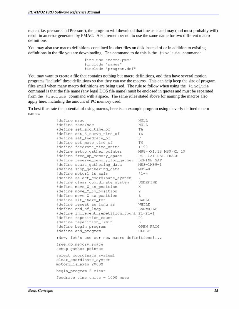
To best illustrate the potential of using macros, here is an example program using cleverly defined macro names:
#define msec NULL #define revs/sec NULL #define set_acc_time_of TA #define set_S_curve_time_of TS #define set_feedrate_of F #define set_move_time_of TM #define feedrate_time_units I190 #define setup_gather_pointer M88->X1,18 M89>X1,19 #define free_up_memory_space DEL GAT DEL TRACE #define reserve_memory_for_gather DEFINE GAT #define start_gathering_data M88=1M89=1 #define stop_gathering_data M89=0 #define motor1_is_axis #1-> #define select_coordinate_system & #define clear_coordinate_system UNDEFINE #define move_X_to_position X #define move_Y_to_position Y #define move_Z_to_position Z #define sit_there_for DWELL #define repeat_as_long_as WHILE #define end_of_loop ENDWHILE #define increment_repetition_count P1=P1+1 #define repetition_count P1 #define repetition_limit 3 #define begin_program OPEN PROG #define end_program CLOSE
;Now, let's use our new macro definitions!...
free_up_memory_space setup_gather_pointer
select_coordinate_system1 clear_coordinate_system motor1_is_axis 2000X
begin_program 2 clear
feedrate_time_units = 1000 msec
Basic Concepts 15
PEWIN32 PRO Software Reference Manual
set_acc_time_of 200 msec set_S_curve_time_of 50 msec repetition_count = 0 set_feedrate_of 1 revs/sec start_gathering_data
repeat_as_long_as(repetition_count<repetition_limit) move_X_to_position 2 sit_there_for 300 msec move_X_to_position 0 sit_there_for 400 msec increment_repetition_count end_of_loop
stop_gathering_data end_program
reserve_memory_for_gather
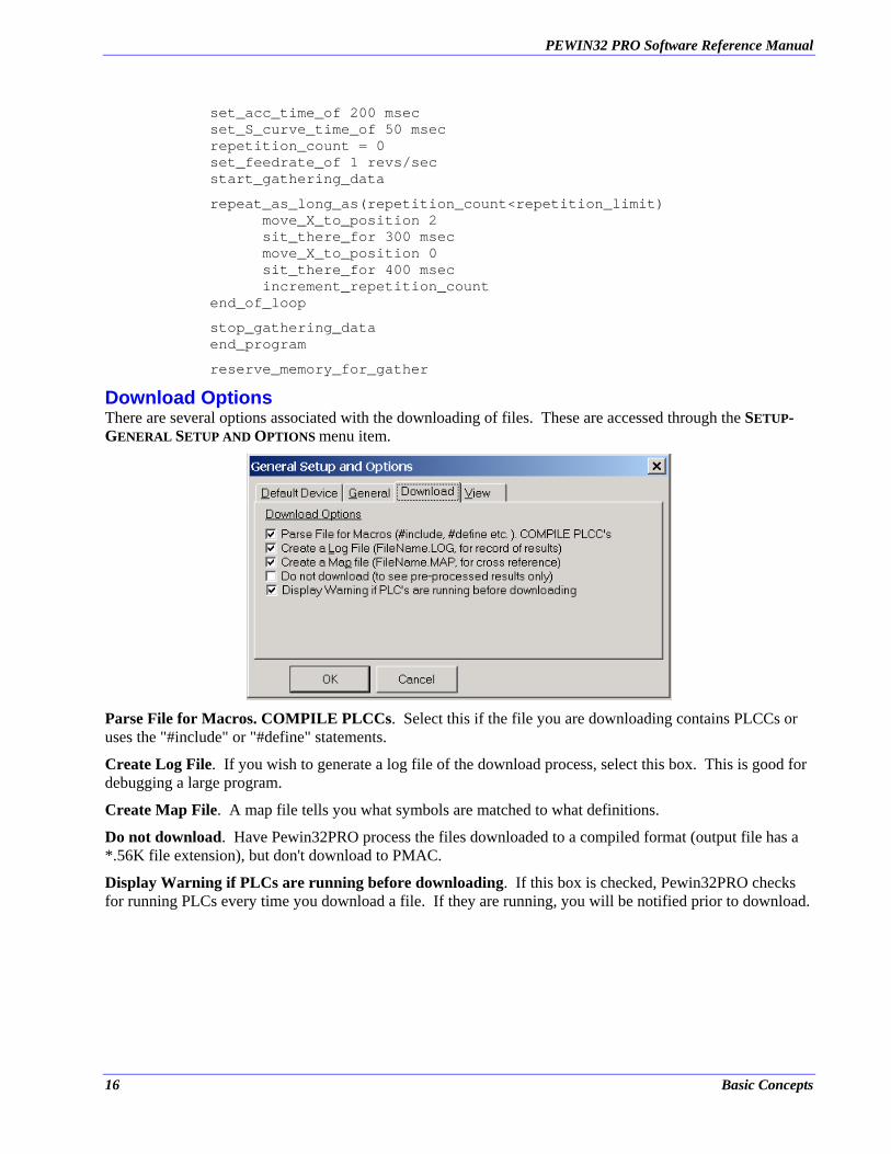
Download Options There are several options associated with the downloading of files. These are accessed through the SETUP- GENERAL SETUP AND OPTIONS menu item.
Parse File for Macros. COMPILE PLCCs. Select this if the file you are downloading contains PLCCs or uses the "#include" or "#define" statements.
Create Log File. If you wish to generate a log file of the download process, select this box. This is good for debugging a large program.
Create Map File. A map file tells you what symbols are matched to what definitions.
Do not download. Have Pewin32PRO process the files downloaded to a compiled format (output file has a *.56K file extension), but don't download to PMAC.
Display Warning if PLCs are running before downloading. If this box is checked, Pewin32PRO checks for running PLCs every time you download a file. If they are running, you will be notified prior to download.
16 Basic Concepts

PEWIN32 PRO Software Reference Manual
Terminal The Terminal represents a direct connection to a PMAC. There are two parts to the Terminal, the Entry and Response windows. Any characters you type at the keyboard are sent to PMAC after pressing <ENTER>. Any characters that are sent from PMAC to the PC are displayed on the response window in a color corresponding to the current communications mode. If any command is rejected by PMAC, an error code is shown as well as its description (and possible remedies) displayed in red text (assuming I6 is set to 1, the default). You should always read this text, as it may affect your application.
The entry window keeps track of all unique commands sent to PMAC. To retrieve a previously sent command, press the down arrow to view to the bottom right of the window, select and press <Enter>. This is especially useful when, for example, you constantly have to type in a lengthy command phrase such as: RHY$C000,20.
If you have SEND or CMD statements which cause PMAC to send ‘unsolicited’ strings to the host PC, you may want to close all windows except the terminal window to ensure these strings are captured and displayed by the Terminal window. Other open windows, which periodically poll PMAC, can inadvertently destroy unsolicited responses.
Changing the Appearance of the Terminal Select the Terminal window so that the Terminal menu item appears. Choose the Terminal | Select Colors or Terminal | Select Font menu items for changing the appearance of the terminal.
Basic Concepts 17
PEWIN32 PRO Software Reference Manual
Selecting DPRAM ASCII Communication By selecting DPRAM ASCII communication, you can enable or disable the DPRAM communication provided that PMAC has DPRAM and it is configured.
Note
Only ISA, PCI and USB modes of communication support DPRAM ASCII communication.
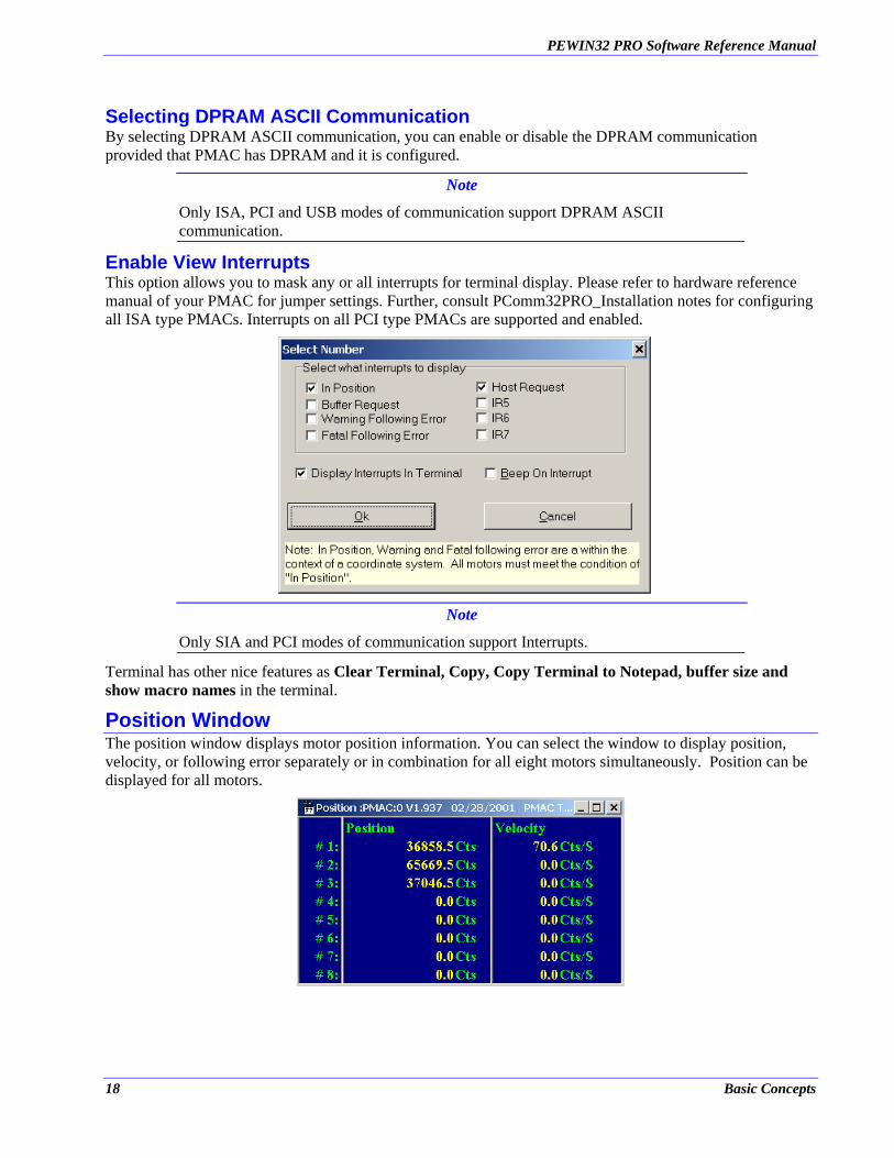
Enable View Interrupts This option allows you to mask any or all interrupts for terminal display. Please refer to hardware reference manual of your PMAC for jumper settings. Further, consult PComm32PRO_Installation notes for configuring all ISA type PMACs. Interrupts on all PCI type PMACs are supported and enabled.
Note
Only SIA and PCI modes of communication support Interrupts.
Terminal has other nice features as Clear Terminal, Copy, Copy Terminal to Notepad, buffer size and show macro names in the terminal.
Position Window The position window displays motor position information. You can select the window to display position, velocity, or following error separately or in combination for all eight motors simultaneously. Position can be displayed for all motors.
18 Basic Concepts
PEWIN32 PRO Software Reference Manual
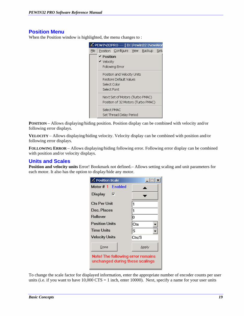
Position Menu When the Position window is highlighted, the menu changes to :
POSITION – Allows displaying/hiding position. Position display can be combined with velocity and/or following error displays.
VELOCITY – Allows displaying/hiding velocity. Velocity display can be combined with position and/or following error displays.
FOLLOWING ERROR – Allows displaying/hiding following error. Following error display can be combined with position and/or velocity displays.
Units and Scales Position and velocity units Error! Bookmark not defined.– Allows setting scaling and unit parameters for each motor. It also has the option to display/hide any motor.
To change the scale factor for displayed information, enter the appropriate number of encoder counts per user units (i.e. if you want to have 10,000 CTS = 1 inch, enter 10000). Next, specify a name for your user units
Basic Concepts 19
PEWIN32 PRO Software Reference Manual
(i.e. “inch”, “deg”, “rev”). Select your velocity units (i.e. "per ms", “per second” or “per minute”). Enter in a value for optional rolloverError! Bookmark not defined. (i.e. 360 if your user units are degrees). A value of 0 for rollover indicates no rollover. Lastly, specify how many decimal places to the right of the decimal point you wish to have displayed (for inches, you may want to use a value of 3 so inches are displayed as “2.002 inches”). These parameters affect only the way information is displayed in the position window. They have no connection to PMAC itself.
Note
Only an active (Ix00 = 1) motor’s parameters can be modified. Also, note that the following error remains unchanged during these scalings.
Deselecting the display check box associated with a motor will cause the position window to not display information about that motor. This allows systems to display/hide any given motor.
RESTORE DEFAULT VALUES - Reverts all settings to Pewin32PRO’s default settings, including display mode, Cts/Unit, Dec. places, Rollover and units for Position and Velocity.
SELECT FONT | SELECT COLOR - Allows changing the appearance of the Position window.
NEXT SET OF MOTORS - Allows display of any one set of the motors for Turbo PMACs. By pressing the <PgUp>, <PgDn> or the <UpArrow>, <DownArrow> keys it is possible to change to the next set of motors in that order.
POSITION OF 32 MOTORS - Allows display of position only for all 32 motors for Turbo PMACs.
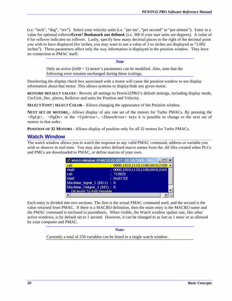
Watch Window The watch window allows you to watch the response to any valid PMAC command, address or variable you wish to observe in real-time. You may also select defined macro names from the .tbl files created when PLCs and PMCs are downloaded to PMAC, or define macros of your own.
Each entry is divided into two sections. The first is the actual PMAC command used, and the second is the value returned from PMAC. If there is a MACRO definition, then the main entry is the MACRO name and the PMAC command is enclosed in parenthesis. When visible, the Watch window update rate, like other active windows, is by default set to 1 second. However, it can be changed to as fast as 1 msec or as allowed by your computer and PMAC.
Note:
Currently a total of 250 variables can be listed in a single watch window.
20 Basic Concepts
PEWIN32 PRO Software Reference Manual
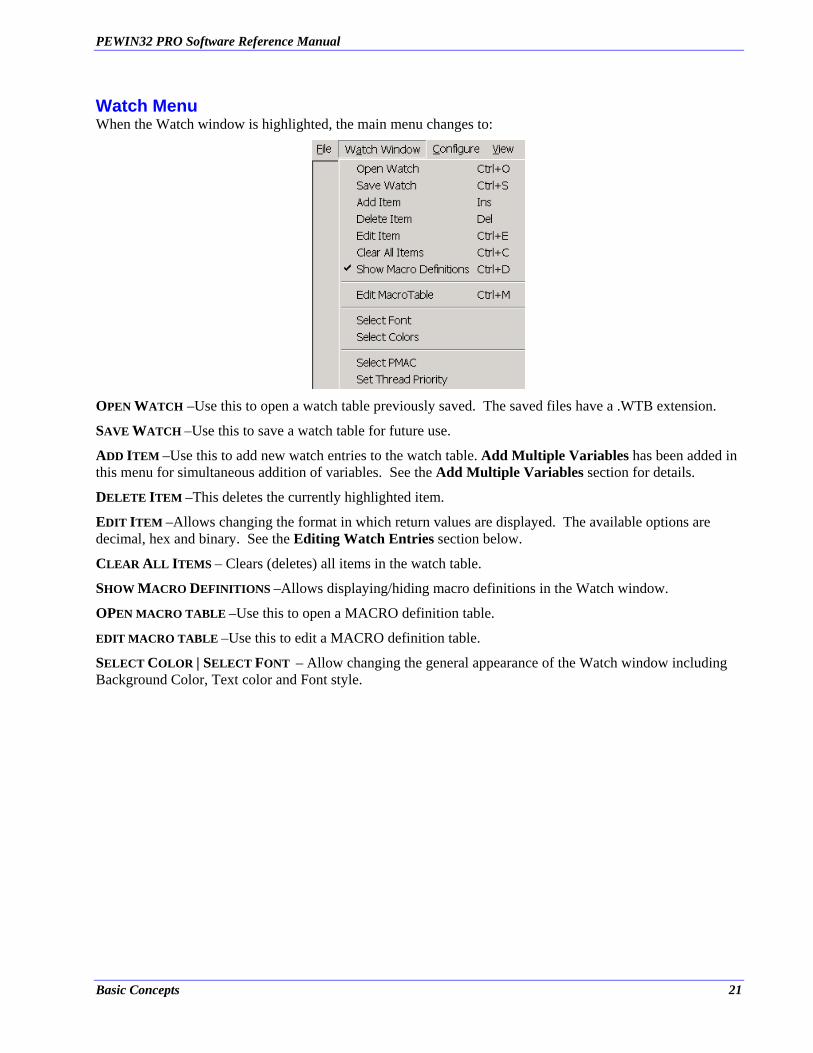
Watch Menu When the Watch window is highlighted, the main menu changes to:
OPEN WATCH –Use this to open a watch table previously saved. The saved files have a .WTB extension.
SAVE WATCH –Use this to save a watch table for future use.
ADD ITEM –Use this to add new watch entries to the watch table. Add Multiple Variables has been added in this menu for simultaneous addition of variables. See the Add Multiple Variables section for details.
DELETE ITEM –This deletes the currently highlighted item.
EDIT ITEM –Allows changing the format in which return values are displayed. The available options are decimal, hex and binary. See the Editing Watch Entries section below.
CLEAR ALL ITEMS – Clears (deletes) all items in the watch table.
SHOW MACRO DEFINITIONS –Allows displaying/hiding macro definitions in the Watch window.
OPEN MACRO TABLE –Use this to open a MACRO definition table.
EDIT MACRO TABLE –Use this to edit a MACRO definition table.
SELECT COLOR | SELECT FONT – Allow changing the general appearance of the Watch window including Background Color, Text color and Font style.
Basic Concepts 21

PEWIN32 PRO Software Reference Manual
Adding Entries to the Watch Window When the Watch window is highlighted, pressing the <INSERT> key or selecting ADD ITEM... from the Watch menu brings up the Add a Variable dialog interface.
Simply type in the PMAC command you wish to watch the status of and press the Add button. The entered command will then be displayed in the watch window. Add as many items as you want, then select the Done button to return to the Watch window. You can also select any defined macros from the macro drop down list. From this window, you could edit the macro table, by clicking on the Editing Macros button. The Add Multiple Variables button lets you add multiple variables to the watch window. You could add multiple variables in this window by separating every variable with a semicolon. For example, to add four variables to the watch window at the same time, you could do: p1;i130;q10;m1. Include Non Macro Variables check box, allows you to include all the non-macro variables to the drop down list box, which are added the watch window.
Adding and Editing Macro Definitions Pewin32Pro's Watch window has a built in macro management facility. You are able to load and save macro files (like those produced by downloading files to PMAC) as well as add, edit and delete entries in those files. Once these macros are set up, instead of typing variables into the Add Watch dialog, you can select them from the macro list and view their status in the Watch window.
Simply select the entry you wish to watch and select the Add button.
22 Basic Concepts

PEWIN32 PRO Software Reference Manual
Editing Macros Pewin32Pro’s watch table contains a full macro configuration utility. This will allow you to create, edit and delete macros as well as save and load macro tables to disk.
These can then be selected from the list in the Add Watch Item dialog box. Selecting the Add or Edit buttons will allow you to assign or change a Macro.
Specify a macro name and its corresponding PMAC command or variable. Pressing the Edit button will add or change this macro definition in the macro list.
Selecting the Remove button will remove the currently highlighted macro definition. Remove All will clear all the entries.
To display PLC or PMC macros in the Watch window, load the .tbl file (created when the PLC or PMC was downloaded) by selecting the Load button. Select the appropriate file and press <ENTER>. Once a macro table has been loaded, it name is displayed in the Add Watch dialog. Open the list box by clicking on the small arrow button to the right of the command line to display a list of loaded macro definitions.
The Load and Save buttons prompt the user for a file and perform the specified operation.
Add Multiple Variables A new interface Add Multiple Variables has been added to the Watch window. This adding more than one variable in the watch window. It also allows you to add more than one macro variable to the watch window.
Basic Concepts 23
PEWIN32 PRO Software Reference Manual
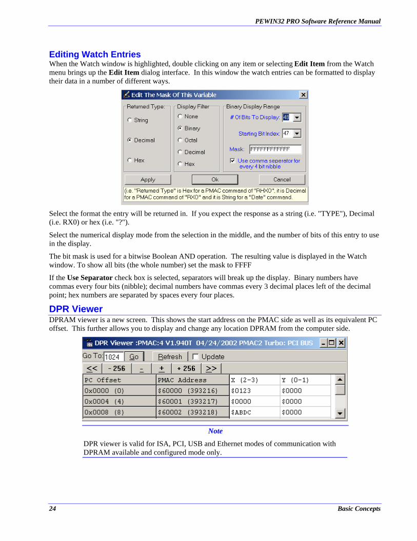
Editing Watch Entries When the Watch window is highlighted, double clicking on any item or selecting Edit Item from the Watch menu brings up the Edit Item dialog interface. In this window the watch entries can be formatted to display their data in a number of different ways.
Select the format the entry will be returned in. If you expect the response as a string (i.e. "TYPE"), Decimal (i.e. RX0) or hex (i.e. "?").
Select the numerical display mode from the selection in the middle, and the number of bits of this entry to use in the display.
The bit mask is used for a bitwise Boolean AND operation. The resulting value is displayed in the Watch window. To show all bits (the whole number) set the mask to FFFF
If the Use Separator check box is selected, separators will break up the display. Binary numbers have commas every four bits (nibble); decimal numbers have commas every 3 decimal places left of the decimal point; hex numbers are separated by spaces every four places.
DPR Viewer DPRAM viewer is a new screen. This shows the start address on the PMAC side as well as its equivalent PC offset. This further allows you to display and change any location DPRAM from the computer side.
Note
DPR viewer is valid for ISA, PCI, USB and Ethernet modes of communication with DPRAM available and configured mode only.
24 Basic Concepts
PEWIN32 PRO Software Reference Manual
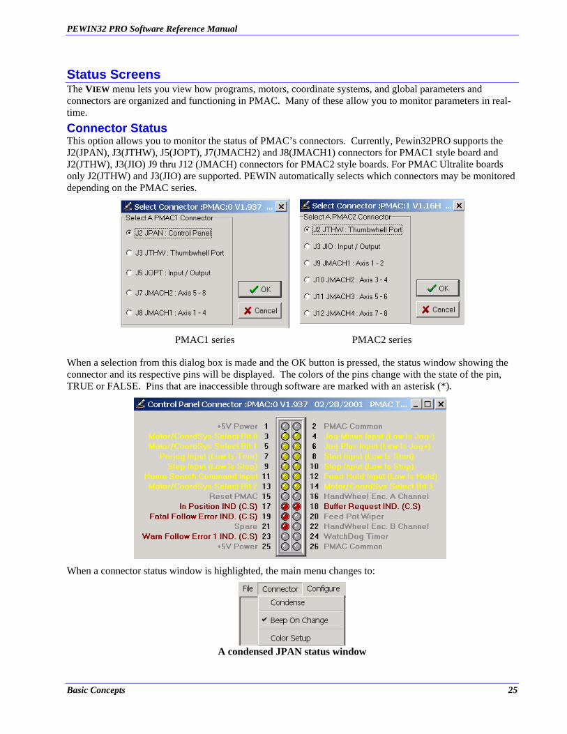
Status Screens The VIEW menu lets you view how programs, motors, coordinate systems, and global parameters and connectors are organized and functioning in PMAC. Many of these allow you to monitor parameters in real-time. Connector Status This option allows you to monitor the status of PMAC’s connectors. Currently, Pewin32PRO supports the J2(JPAN), J3(JTHW), J5(JOPT), J7(JMACH2) and J8(JMACH1) connectors for PMAC1 style board and J2(JTHW), J3(JIO) J9 thru J12 (JMACH) connectors for PMAC2 style boards. For PMAC Ultralite boards only J2(JTHW) and J3(JIO) are supported. PEWIN automatically selects which connectors may be monitored depending on the PMAC series.
PMAC1 series PMAC2 series
When a selection from this dialog box is made and the OK button is pressed, the status window showing the connector and its respective pins will be displayed. The colors of the pins change with the state of the pin, TRUE or FALSE. Pins that are inaccessible through software are marked with an asterisk (*).
When a connector status window is highlighted, the main menu changes to:
A condensed JPAN status window
Basic Concepts 25
PEWIN32 PRO Software Reference Manual
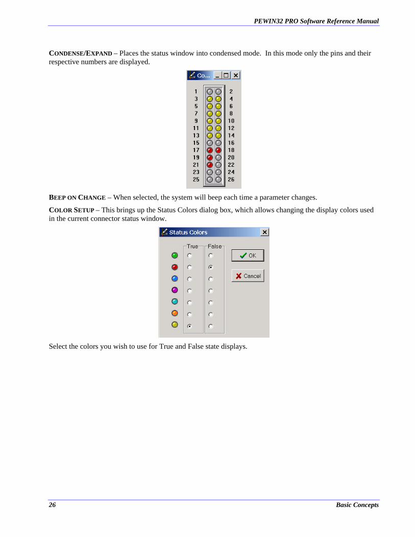
CONDENSE/EXPAND – Places the status window into condensed mode. In this mode only the pins and their respective numbers are displayed.
BEEP ON CHANGE – When selected, the system will beep each time a parameter changes.
COLOR SETUP – This brings up the Status Colors dialog box, which allows changing the display colors used in the current connector status window.
Select the colors you wish to use for True and False state displays.
26 Basic Concepts
PEWIN32 PRO Software Reference Manual
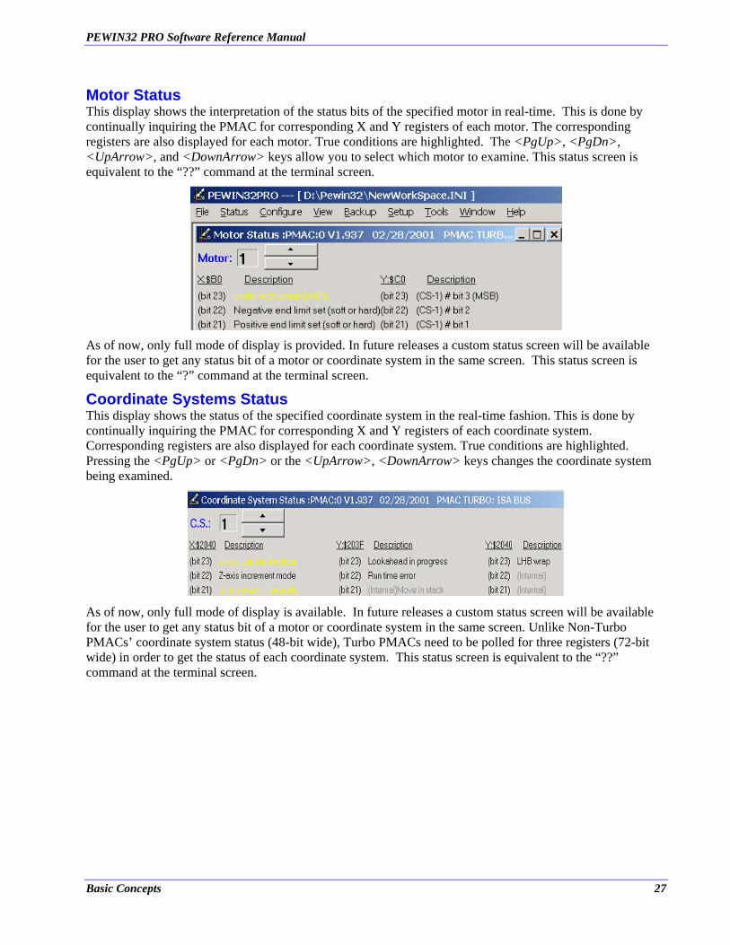
Motor Status This display shows the interpretation of the status bits of the specified motor in real-time. This is done by continually inquiring the PMAC for corresponding X and Y registers of each motor. The corresponding registers are also displayed for each motor. True conditions are highlighted. The <PgUp>, <PgDn>, <UpArrow>, and <DownArrow> keys allow you to select which motor to examine. This status screen is equivalent to the “??” command at the terminal screen.
As of now, only full mode of display is provided. In future releases a custom status screen will be available for the user to get any status bit of a motor or coordinate system in the same screen. This status screen is equivalent to the “?” command at the terminal screen.
Coordinate Systems Status This display shows the status of the specified coordinate system in the real-time fashion. This is done by continually inquiring the PMAC for corresponding X and Y registers of each coordinate system. Corresponding registers are also displayed for each coordinate system. True conditions are highlighted. Pressing the <PgUp> or <PgDn> or the <UpArrow>, <DownArrow> keys changes the coordinate system being examined.
As of now, only full mode of display is available. In future releases a custom status screen will be available for the user to get any status bit of a motor or coordinate system in the same screen. Unlike Non-Turbo PMACs’ coordinate system status (48-bit wide), Turbo PMACs need to be polled for three registers (72-bit wide) in order to get the status of each coordinate system. This status screen is equivalent to the “??” command at the terminal screen.
Basic Concepts 27
PEWIN32 PRO Software Reference Manual
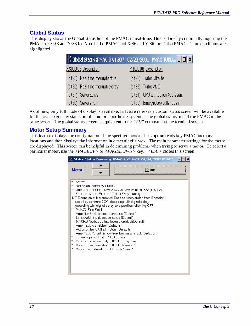
Global Status This display shows the Global status bits of the PMAC in real-time. This is done by continually inquiring the PMAC for X:$3 and Y:$3 for Non-Turbo PMAC and X:$6 and Y:$6 for Turbo PMACs. True conditions are highlighted.
As of now, only full mode of display is available. In future releases a custom status screen will be available for the user to get any status bit of a motor, coordinate system or the global status bits of the PMAC in the same screen. The global status screen is equivalent to the “???” command at the terminal screen.
Motor Setup Summary This feature displays the configuration of the specified motor. This option reads key PMAC memory locations and then displays the information in a meaningful way. The main parameter settings for the motor are displayed. This screen can be helpful in determining problems when trying to servo a motor. To select a particular motor, use the <PAGEUP> or <PAGEDOWN> key. <ESC> closes this screen.
28 Basic Concepts
PEWIN32 PRO Software Reference Manual
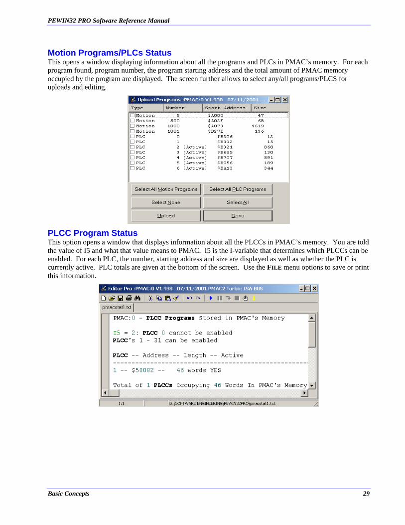
Motion Programs/PLCs Status This opens a window displaying information about all the programs and PLCs in PMAC’s memory. For each program found, program number, the program starting address and the total amount of PMAC memory occupied by the program are displayed. The screen further allows to select any/all programs/PLCS for uploads and editing.
PLCC Program Status This option opens a window that displays information about all the PLCCs in PMAC’s memory. You are told the value of I5 and what that value means to PMAC. I5 is the I-variable that determines which PLCCs can be enabled. For each PLC, the number, starting address and size are displayed as well as whether the PLC is currently active. PLC totals are given at the bottom of the screen. Use the FILE menu options to save or print this information.
Basic Concepts 29

PEWIN32 PRO Software Reference Manual
30 Basic Concepts
PEWIN32 PRO Software Reference Manual
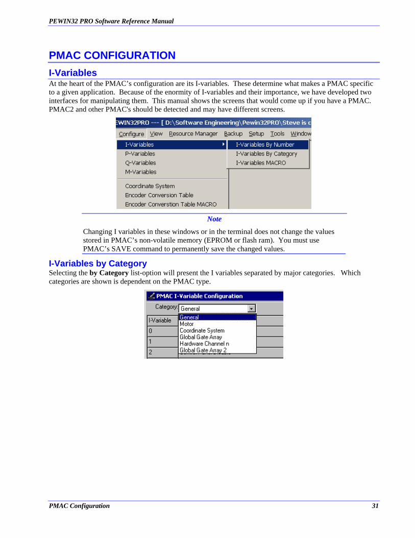
PMAC CONFIGURATION I-Variables At the heart of the PMAC’s configuration are its I-variables. These determine what makes a PMAC specific to a given application. Because of the enormity of I-variables and their importance, we have developed two interfaces for manipulating them. This manual shows the screens that would come up if you have a PMAC. PMAC2 and other PMAC's should be detected and may have different screens.
Note
Changing I variables in these windows or in the terminal does not change the values stored in PMAC’s non-volatile memory (EPROM or flash ram). You must use PMAC’s SAVE command to permanently save the changed values.
I-Variables by Category Selecting the by Category list-option will present the I variables separated by major categories. Which categories are shown is dependent on the PMAC type.
PMAC Configuration 31
PEWIN32 PRO Software Reference Manual
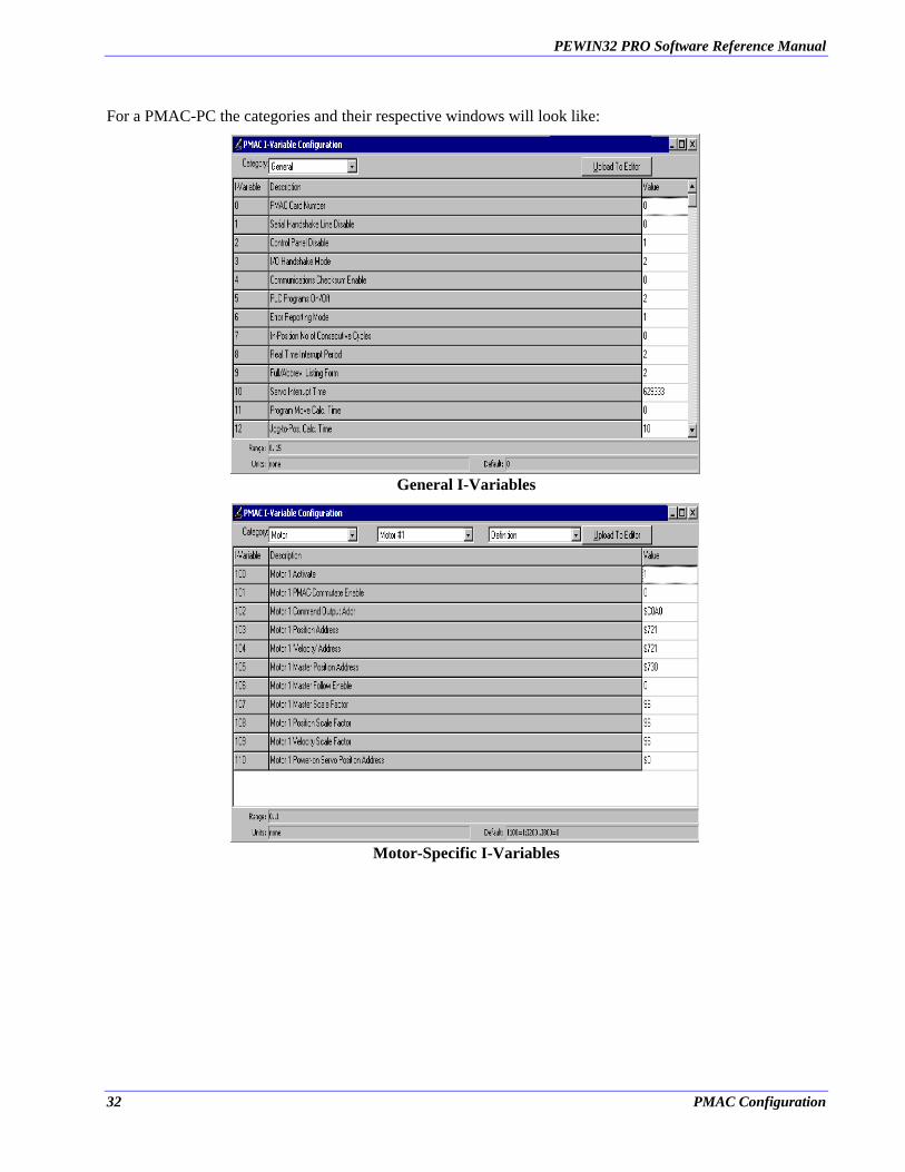
For a PMAC-PC the categories and their respective windows will look like:
General I-Variables
Motor-Specific I-Variables
32 PMAC Configuration
PEWIN32 PRO Software Reference Manual
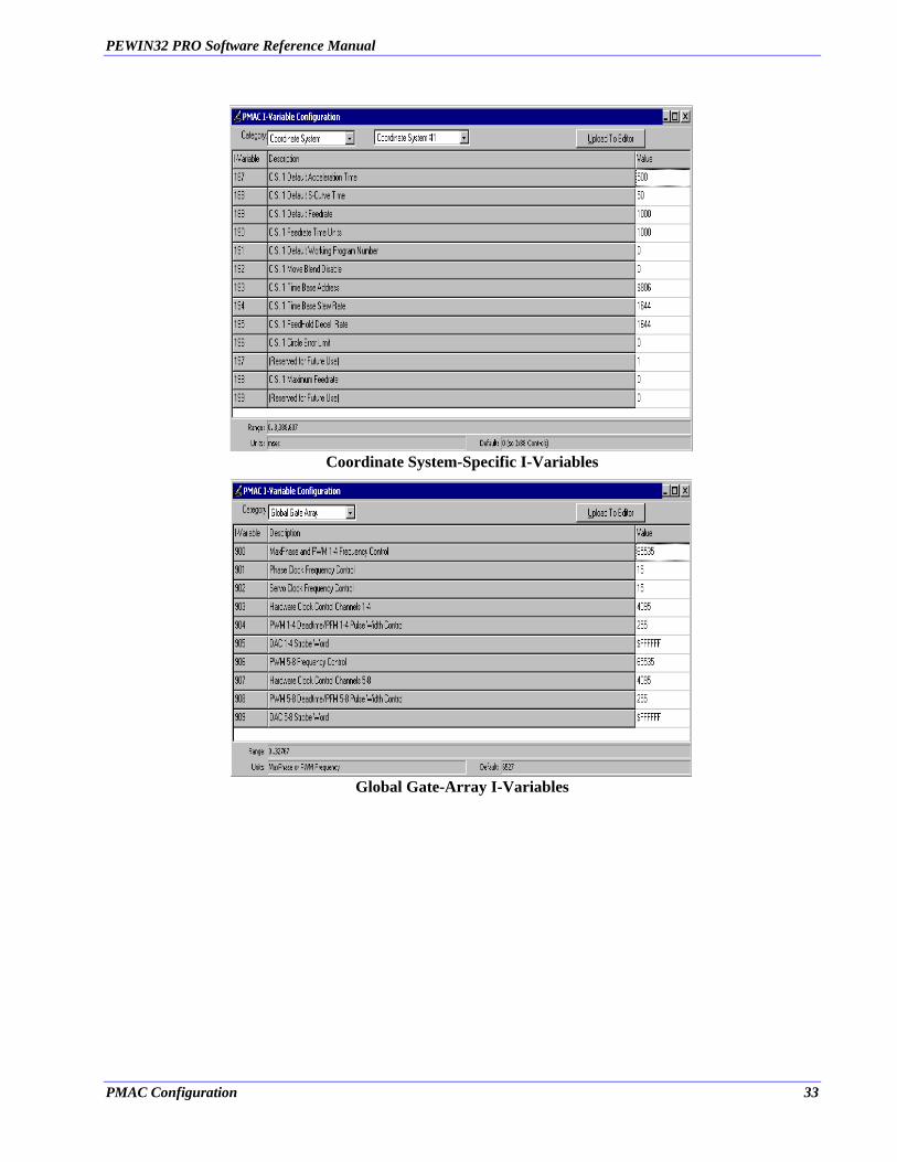
Coordinate System-Specific I-Variables
Global Gate-Array I-Variables
PMAC Configuration 33
PEWIN32 PRO Software Reference Manual
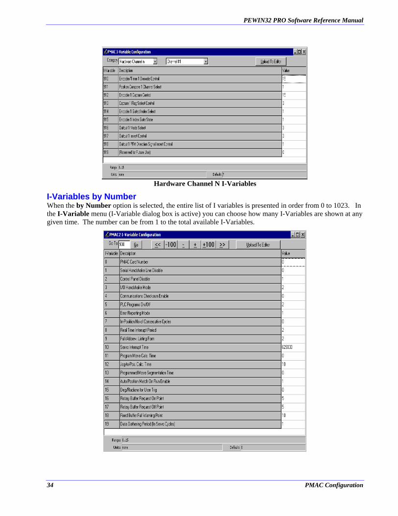
Hardware Channel N I-Variables
I-Variables by Number When the by Number option is selected, the entire list of I variables is presented in order from 0 to 1023. In the I-Variable menu (I-Variable dialog box is active) you can choose how many I-Variables are shown at any given time. The number can be from 1 to the total available I-Variables.
34 PMAC Configuration
PEWIN32 PRO Software Reference Manual
To move through the list, use the two arrow buttons on either side of the window or use the Go To button to jump to a specific variable.
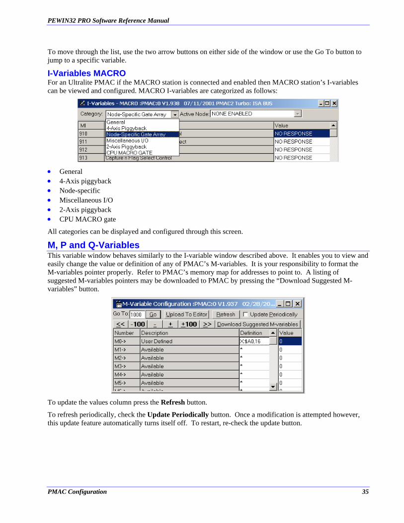
I-Variables MACRO For an Ultralite PMAC if the MACRO station is connected and enabled then MACRO station’s I-variables can be viewed and configured. MACRO I-variables are categorized as follows:
• • • • • •
General 4-Axis piggyback Node-specific Miscellaneous I/O 2-Axis piggyback CPU MACRO gate
All categories can be displayed and configured through this screen.
M, P and Q-Variables This variable window behaves similarly to the I-variable window described above. It enables you to view and easily change the value or definition of any of PMAC’s M-variables. It is your responsibility to format the M-variables pointer properly. Refer to PMAC’s memory map for addresses to point to. A listing of suggested M-variables pointers may be downloaded to PMAC by pressing the “Download Suggested M-variables” button.
To update the values column press the Refresh button.
To refresh periodically, check the Update Periodically button. Once a modification is attempted however, this update feature automatically turns itself off. To restart, re-check the update button.
PMAC Configuration 35
PEWIN32 PRO Software Reference Manual
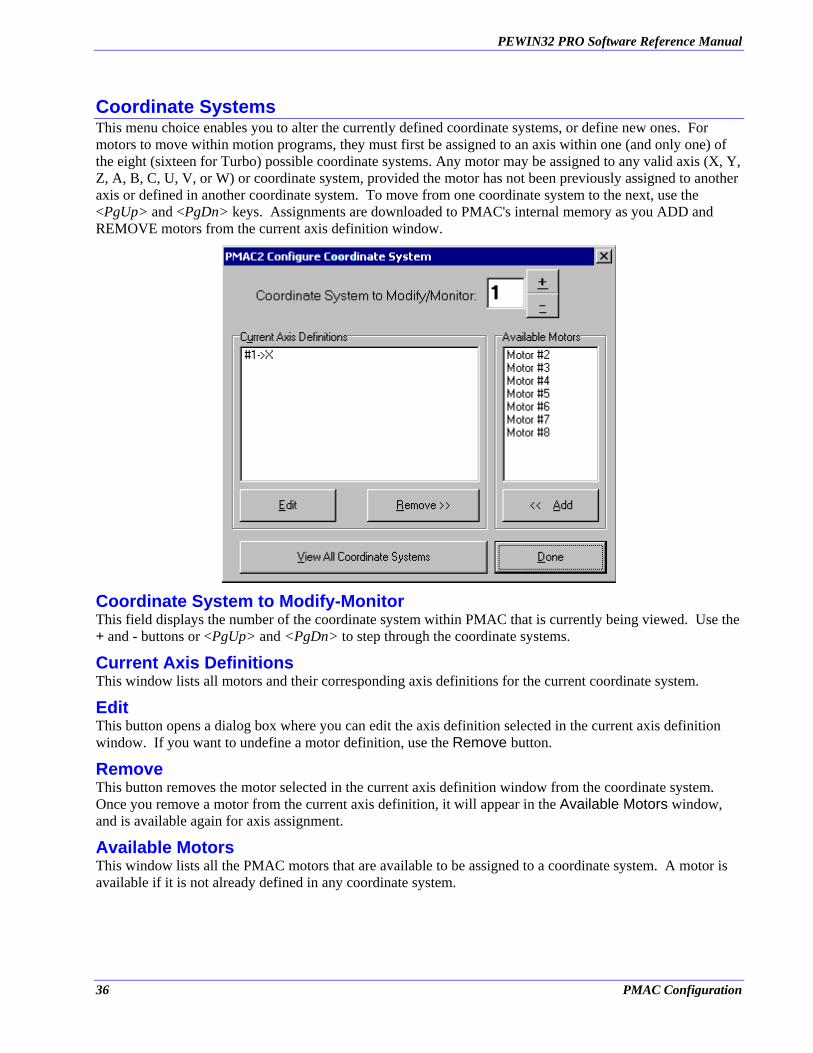
Coordinate Systems This menu choice enables you to alter the currently defined coordinate systems, or define new ones. For motors to move within motion programs, they must first be assigned to an axis within one (and only one) of the eight (sixteen for Turbo) possible coordinate systems. Any motor may be assigned to any valid axis (X, Y, Z, A, B, C, U, V, or W) or coordinate system, provided the motor has not been previously assigned to another axis or defined in another coordinate system. To move from one coordinate system to the next, use the <PgUp> and <PgDn> keys. Assignments are downloaded to PMAC's internal memory as you ADD and REMOVE motors from the current axis definition window.
Coordinate System to Modify-Monitor This field displays the number of the coordinate system within PMAC that is currently being viewed. Use the + and - buttons or <PgUp> and <PgDn> to step through the coordinate systems.
Current Axis Definitions This window lists all motors and their corresponding axis definitions for the current coordinate system.
Edit This button opens a dialog box where you can edit the axis definition selected in the current axis definition window. If you want to undefine a motor definition, use the Remove button.
Remove This button removes the motor selected in the current axis definition window from the coordinate system. Once you remove a motor from the current axis definition, it will appear in the Available Motors window, and is available again for axis assignment.
Available Motors This window lists all the PMAC motors that are available to be assigned to a coordinate system. A motor is available if it is not already defined in any coordinate system.
36 PMAC Configuration

PEWIN32 PRO Software Reference Manual
Add This button adds the motor selected in the Available Motors window to the current axis definition window. When you press this button, a dialog box opens where you can enter the axis definition for the motor before it is added to the coordinate system.
View all Coordinate Systems This option opens a window containing a list of all PMAC coordinate systems and their axis definitions. You cannot edit the coordinate system definitions in this window, but you can print this information.
Done This closes the Configure Coordinate Systems window. For Turbo PMAC systems, a message box may pop up telling you the optimal setting for I68 (Maximum Coordinate System).
Encoder Conversion Table This menu choice allows you to alter, update, save or retrieve the entries of the encoder conversion table. You will need to alter this table in order to use various types of feedback devices other than the default 1/T Conversion that typically is used for incremental encoders. Each feedback device will have an entry in the table for which PMAC will process every servo period. In order for PMAC to interpret a particular feedback device correctly, the raw data must be converted to the proper format. The choices within this dialog box enable the user to change the conversion process easily, without getting into any meticulous details. Refer to the PMAC User's Manual for specific information on how to edit the conversion table manually (i.e. using PMAC memory read and write commands) or the help menu.
The table entries may be scrolled through using <PgUp> or <PgDn>. Alter the conversion method by selecting one of the conversion types. To change the encoder source address, type a new address or select the one from the pull-down list. To leave the conversion table editing without making any changes in PMAC select DONE or press <ESC>. To update the modified encoder table entry, press the Download Entry button.
PMAC Configuration 37

PEWIN32 PRO Software Reference Manual
Entry Number This field contains the number of the encoder conversion table entry currently being viewed. Use the up and down buttons or <PgUp> and <PgDn> to step through the encoder conversion tables. There are 256 possible table entries.
Entry, Source and Processed Data Addresses The Entry Address is for informational purposes only. It tells where within PMAC’s memory this Encoder Conversion table entry is located. As you may notice by scrolling through the entries, PMAC’s Encoder table entries are in a contiguous block of memory.
The Source Address tells PMAC where in its memory is the raw data to use in the conversion process. You can choose from the drop down list, or you may type in your own address. Typically, this address can be found by reading the manual specific to the type of feedback being used.
Finally, the Processed Data Address is where PMAC stores the result of the conversion calculations. This location is useful because it is needed to configure other features in PMAC (i.e. Master Position Feedback address Ix03, Electronic gearing Ix05, etc.), typically by setting I variables.
Conversion Type This field contains the conversion type for the current entry. Select this entry and press <ENTER> or click on the down arrow to the right of this field to view a list of common conversion types. You can select a conversion type from this list using a mouse or the keyboard arrow keys. If you need to use a conversion type not shown in this list, you will have to enter the data manually from the terminal. Refer to the section entitled "Encoder Conversion Table" in the PMAC User's Manual for help with this process.
38 PMAC Configuration
PEWIN32 PRO Software Reference Manual
View All Entries of Table This option opens a window containing a list of all the defined encoder conversion table entries in PMAC's memory. This window can then be saved to disk or printed.
Download Entry This option sends your encoder conversion table configuration to PMAC's memory. Every time you make changes to the table, you need to download it via this button. At this point, the table will be actually be in use by PMAC. An altered encoder conversion table configuration must be stored in PMAC's permanent EPROM memory (using this button) if it is to survive a power down or cycle reset.
Done This closes the Configure Encoder Conversion Table window. This will not download the present encoder conversion table entry to PMAC. Use the Download Entry to PMAC button if you want this entry to be sent to PMAC.
Inc with Inv-T Ext Short for "incremental with 1/T extension." For incremental encoders, the source address must be one of the DSP-GATE encoder counters. The source address list box will contain the standard entries for your PMAC Type.
Most applications will use the 1/T-extension conversion method that uses timers associated with each counter to estimate fractional resolution.
Those who have set up to use the parallel sub-count interpolation must use a source address of one of the odd-numbered encoders. A typical setup address in this case would be $C010 hex, which provides parallel extension of the encoder 5 counter using encoder 6's flags.
A-D Register This conversion choice picks up data from the top 16 bits of a 24-bit word. It is intended for use with the A/D converter registers in the DSP-gates, which are fed by Accessory 23 or Accessory 28(A or B). The source address list box will contain the standard entries for your PMAC Type.
A typical address for an A/D register would be $C006, which provides the conversion of the ADC2 register. With A/D conversion, there is no rollover (software extension) performed.
Parallel with and without Filter The four choices Parallel Y without Filter, Parallel Y with Filter, Parallel X without Filter, and Parallel X with Filter differ only in the use of X or Y memory space and whether or not the filter is to be used. If you are providing position information to PMAC as a parallel data word (as from an absolute encoder or processed from a laser interferometer) you will use this conversion method. The parallel data word may come from either the X or Y memory space. Usually this data is brought in on an ACC-14 board, which is in the Y-memory space. The source address list box will contain the standard entries for your PMAC Type.
Parallel-feedback conversion requires a double (for non-filtered) or triple (for filtered) entry in the conversion table. The second entry – filtered or non-filtered – specifies the size of the feedback word used. The entry is a 24-bit word in which each bit actually used for the parallel feedback is a one; the unused bits above are zeros (parallel feedback should always be connected starting at bit 0 of the data word). For a 12-bit absolute encoder, this entry would be $000FFF hex; for 14 bits, it would be $003FFF hex. The maximum entry permitted is for 19 bits: $07FFFF hex. The count can be software-extended by PMAC, permitting rollover. If more than 19 bits of true absolute position are needed, the power-on position can be read to full range using Ix09 and Ix10; from then on, position is kept through rollover using the conversion table.
The converted data from the parallel word is put in the X data word matching the last (2nd or 3rd) setup word for the entry. This is the address that should be used by the motor I-variable that picks up position (Ix03, Ix04, or Ix05). For instance, if the first setup entry (address Y:$720) in the conversion table were $30FFD0
PMAC Configuration 39
PEWIN32 PRO Software Reference Manual
hex (filtered parallel data), the size entry would be in Y:$721, and the maximum change entry would be in Y:$722 hex. The converted data would be placed in X:$722 hex. If this were the position feedback for motor #1, Ix03 would be set to $722 hex (1826 decimal).
Note
The parallel data word from a laser interferometer is not true absolute position information, because the interferometer is fundamentally an incremental sensor. For this arrangement, there is no need to wire more than 19 bits of data to the ACC-14 (in fact, 16 bits is sufficient). Position reference is established by a homing procedure, and full range is achieved by using rollover to extend the range of the count in software.
Filter-Max Change The parallel data word filter simply sets a maximum amount the data word is permitted to change in a single servo cycle. This value should be entered in the filter box in hex. If PMAC sees a change larger than this in the source data word, the converted data only changes by the maximum amount. There is no permanent loss of position information if the filter "kicks in." This filtering permits protection against spurious changes on high-order data lines, while not delaying legitimate changes at all. This maximum amount is the third setup entry for the encoder in the Y-memory portion of the conversion table. It should be set slightly greater than the maximum actual velocity expected on the sensor.
Time Base A time-base conversion is a scaled digital differentiation. Every servo cycle, it calculates the difference between the value of the source register for this cycle and the value for the last cycle, and multiplies the difference by the scale factor. The scale factor can be entered under the Bit Enable/Time Base input box. The most common use for the resulting value is for the time-base (feedrate override) control, which makes the speed of PMAC execution proportional to an external frequency (usually the speed of a master device).
Triggered Time Base This is similar to the time base conversion described above, but with the added feature of synchronizing time base following upon a hardware trigger. Refer to the PMAC User's Manual for further reference.
Inc with Parallel Ext Short for "Incremental Encoder with Parallel Extension." Those who have set up to use the parallel sub-count interpolation for incremental feedback would use this option. In this case, the source address must be one of the odd-numbered encoders. A typical source address would be $C010, which provides parallel extension (i.e. interpolation) of encoder #5 counter using encoder #6's flags.
Inc without Parallel Ext Short for "Incremental Encoder without Parallel Extension." Those who have set up to use the parallel incremental feedback without interpolation would use this option.
Summing Table Entries to Another For Turbo PMAC’s select the Summing of Conversion Table Entries for the conversion type. Turbo allows several options when using this conversion type. You may choose to add a table entry to it by disabling the second entry. In addition, either you can negate the first, second or both table items to be summed. Lastly, you may optionally integrate (summation of the results) the results.
For non-Turbo PMAC’s choose the Add with Previous Entry option. This will result in the sum of this entry and the previous entry in the table. Setting this option to Additive in entry number 3 for instance, would result in the summation of entry 2 and entry 3 at the address of location 3. This permits the servo feedback to sum two sensors. (If the polarity of the sensors or their counters is opposite, this provides the difference of the sensors. This can be useful for Doppler-type sensors, where the reference wave and the shifted-frequency
40 PMAC Configuration
PEWIN32 PRO Software Reference Manual
wave are fed into different counters, one counting up, the other counting down; summing the two counters provides position.)
Bits Enabled Mask This field contains a scale factor used when the appropriate bit is enabled. The most common use for the resulting value is for the time-base (feedrate override) control, which makes the speed of PMAC execution proportional to an external frequency (usually the speed of a master device).
Max Change This limits the magnitude that the input value is allowed to change between scans.
Conversion Shifting of Parallel Data If you want to have fractional parts of the position or you have a MACRO station base system then you have to specify that in the conversion shifting of parallel data.
Encoder Conversion Table MACRO For an Ultralite PMAC with MACRO station enabled this menu allows you to alter, update, save or retrieve the entries of the encoder conversion table for MACRO station. Conversion types are similar to the main Encoder conversion table.
PMAC Configuration 41

PEWIN32 PRO Software Reference Manual
42 PMAC Configuration
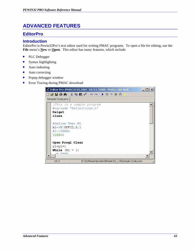
PEWIN32 PRO Software Reference Manual
ADVANCED FEATURES EditorPro Introduction EditorPro is Pewin32Pro’s text editor used for writing PMAC programs. To open a file for editing, use the File menu’s New or Open. This editor has many features, which include:
• • • • • •
PLC Debugger Syntax highlighting Auto indenting Auto correcting Popup debugger window Error Tracing during PMAC download
Advanced Features 43
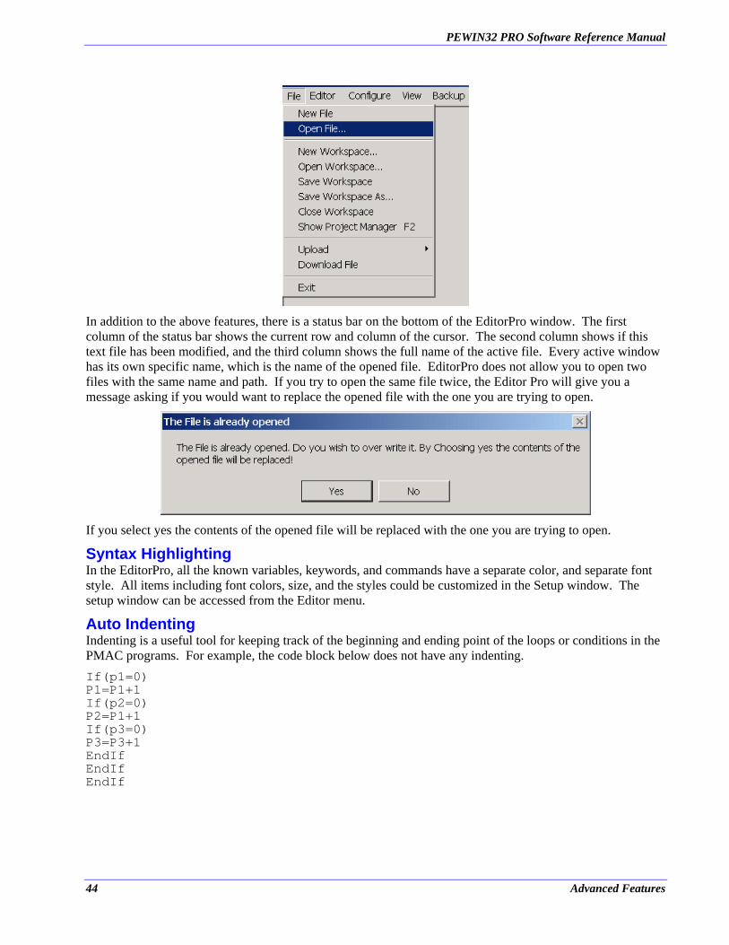
PEWIN32 PRO Software Reference Manual
In addition to the above features, there is a status bar on the bottom of the EditorPro window. The first column of the status bar shows the current row and column of the cursor. The second column shows if this text file has been modified, and the third column shows the full name of the active file. Every active window has its own specific name, which is the name of the opened file. EditorPro does not allow you to open two files with the same name and path. If you try to open the same file twice, the Editor Pro will give you a message asking if you would want to replace the opened file with the one you are trying to open.
If you select yes the contents of the opened file will be replaced with the one you are trying to open.
Syntax Highlighting In the EditorPro, all the known variables, keywords, and commands have a separate color, and separate font style. All items including font colors, size, and the styles could be customized in the Setup window. The setup window can be accessed from the Editor menu.
Auto Indenting Indenting is a useful tool for keeping track of the beginning and ending point of the loops or conditions in the PMAC programs. For example, the code block below does not have any indenting. If(p1=0) P1=P1+1 If(p2=0) P2=P1+1 If(p3=0) P3=P3+1 EndIf EndIf EndIf
44 Advanced Features
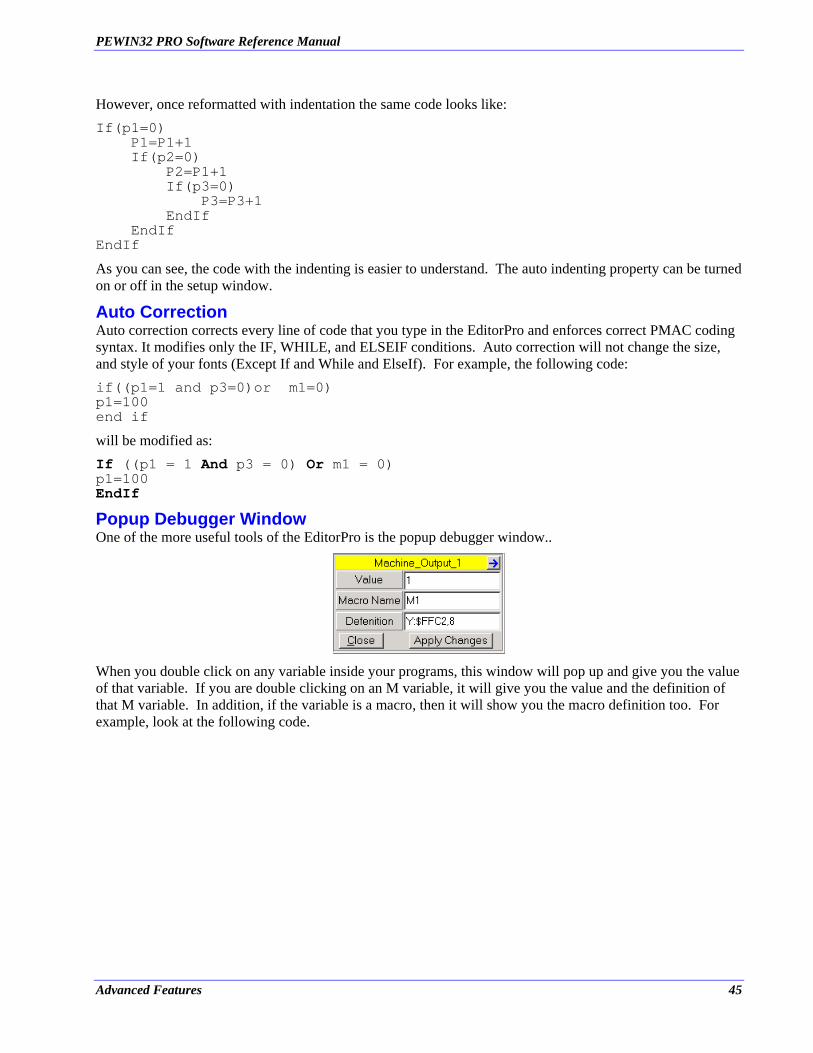
PEWIN32 PRO Software Reference Manual
However, once reformatted with indentation the same code looks like: If(p1=0) P1=P1+1 If(p2=0) P2=P1+1 If(p3=0) P3=P3+1 EndIf EndIf EndIf
As you can see, the code with the indenting is easier to understand. The auto indenting property can be turned on or off in the setup window.
Auto Correction Auto correction corrects every line of code that you type in the EditorPro and enforces correct PMAC coding syntax. It modifies only the IF, WHILE, and ELSEIF conditions. Auto correction will not change the size, and style of your fonts (Except If and While and ElseIf). For example, the following code: if((p1=1 and p3=0)or m1=0) p1=100 end if
will be modified as: If ((p1 = 1 And p3 = 0) Or m1 = 0) p1=100 EndIf
Popup Debugger Window One of the more useful tools of the EditorPro is the popup debugger window..
When you double click on any variable inside your programs, this window will pop up and give you the value of that variable. If you are double clicking on an M variable, it will give you the value and the definition of that M variable. In addition, if the variable is a macro, then it will show you the macro definition too. For example, look at the following code.
Advanced Features 45
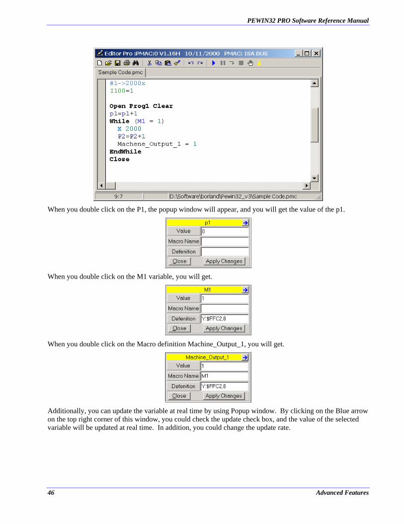
PEWIN32 PRO Software Reference Manual
When you double click on the P1, the popup window will appear, and you will get the value of the p1.
When you double click on the M1 variable, you will get.
When you double click on the Macro definition Machine_Output_1, you will get.
Additionally, you can update the variable at real time by using Popup window. By clicking on the Blue arrow on the top right corner of this window, you could check the update check box, and the value of the selected variable will be updated at real time. In addition, you could change the update rate.
46 Advanced Features
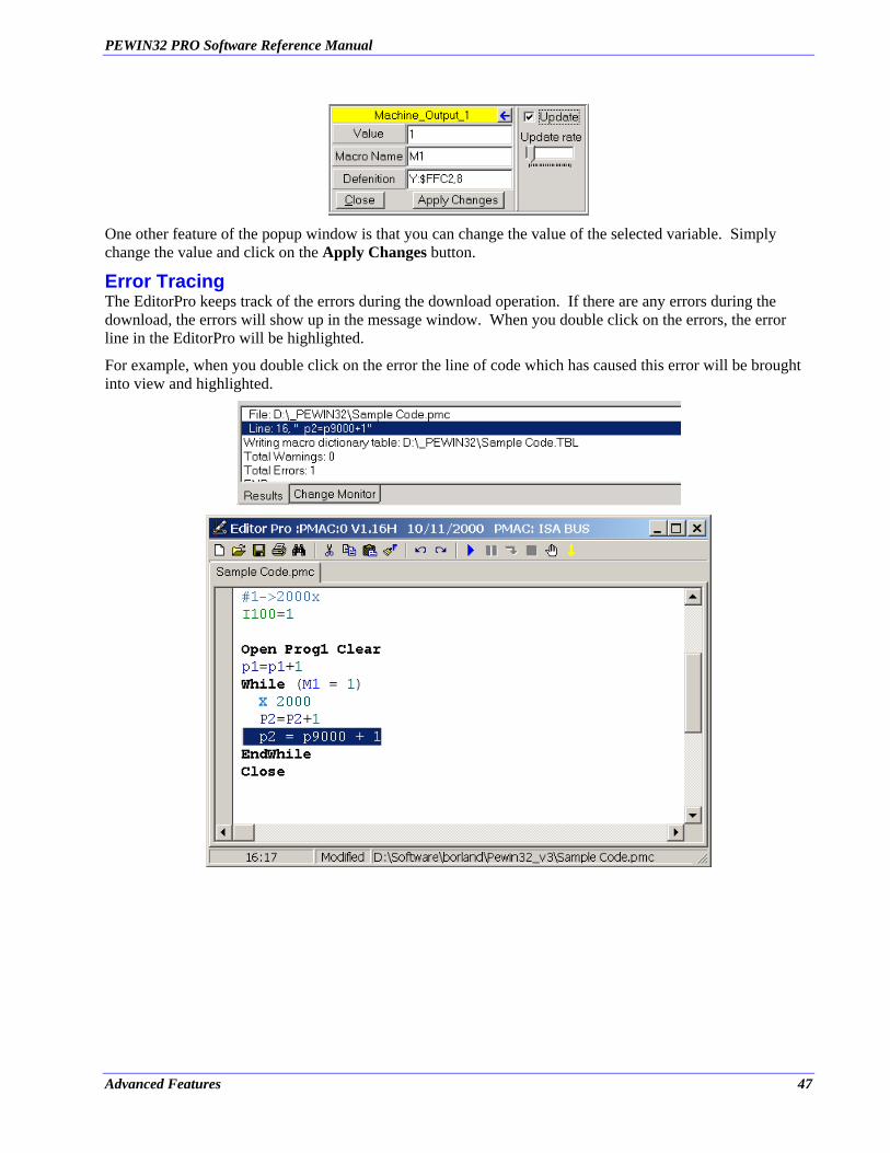
PEWIN32 PRO Software Reference Manual
One other feature of the popup window is that you can change the value of the selected variable. Simply change the value and click on the Apply Changes button.
Error Tracing The EditorPro keeps track of the errors during the download operation. If there are any errors during the download, the errors will show up in the message window. When you double click on the errors, the error line in the EditorPro will be highlighted.
For example, when you double click on the error the line of code which has caused this error will be brought into view and highlighted.
Advanced Features 47

PEWIN32 PRO Software Reference Manual
Editor Menu The following is the editor menu. To open the editor menu, select the editor from the main menu, or right click in the editor. There is another static menu on top of the EditorPro window, which links to some of the functions in the editor menu. In addition, some of the items in the editor menu have shortcut keys.
• Open Source/Header File (Ctrl+H): If there are any header files included in your program, clicking on this menu item will open the header file. If the file that you are working on is not a header file, and there are no header files included in that program, then Editor Pro will create a new header file with the same name of the file, but with an extension of .H. However, before it creates the file it will ask you if you want to save and include the newly created header file in your program.
If you select yes, EditorPro will include the header file in your main program automatically, and will save it as well.
If the file that you are working on is a header file with an extension .H, then EditorPro will try to open a file with the same name but with a different extension. For example, if the header file name is Sample Program.h then it will try to open the file Sample Program.pmc or with any other extension. If the file does not exist, then the following window will appear.
48 Advanced Features
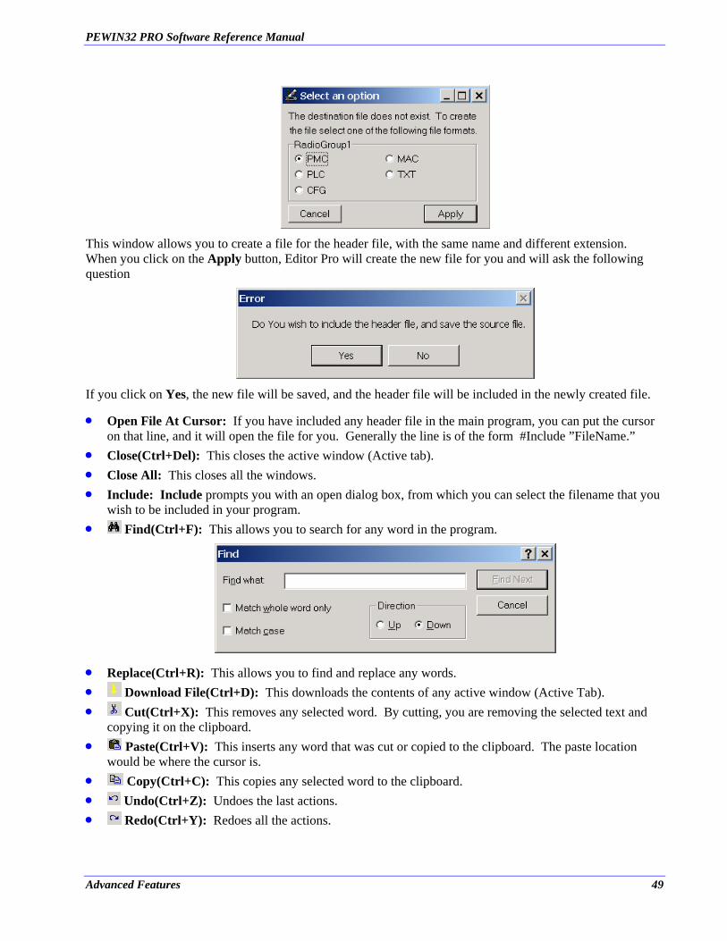
PEWIN32 PRO Software Reference Manual
This window allows you to create a file for the header file, with the same name and different extension. When you click on the Apply button, Editor Pro will create the new file for you and will ask the following question
If you click on Yes, the new file will be saved, and the header file will be included in the newly created file.
•
• • •
•
Open File At Cursor: If you have included any header file in the main program, you can put the cursor on that line, and it will open the file for you. Generally the line is of the form #Include ”FileName.” Close(Ctrl+Del): This closes the active window (Active tab). Close All: This closes all the windows. Include: Include prompts you with an open dialog box, from which you can select the filename that you wish to be included in your program.
Find(Ctrl+F): This allows you to search for any word in the program.
• •
Replace(Ctrl+R): This allows you to find and replace any words. Download File(Ctrl+D): This downloads the contents of any active window (Active Tab).
• Cut(Ctrl+X): This removes any selected word. By cutting, you are removing the selected text and copying it on the clipboard.
• Paste(Ctrl+V): This inserts any word that was cut or copied to the clipboard. The paste location would be where the cursor is.
• Copy(Ctrl+C): This copies any selected word to the clipboard. • Undo(Ctrl+Z): Undoes the last actions. • Redo(Ctrl+Y): Redoes all the actions.
Advanced Features 49

PEWIN32 PRO Software Reference Manual
• Save(Ctrl+S): Saves the contents of the active window (Active Tab). If the file does not exist, then the Save As function will be executed.
• •
Save As: Allows you to save any file under a different name. Print(Ctrl+P): Prints the contents of the active window. It can also print any selected text.
• Setup: Opens the Setup Window.
Select PMAC: Allows you to select a different PMAC device for the active window. Every window (Tab) of the EditorPro can have a different PMAC device.
Setup Window In the setup window, you can change the general, font, and font color settings of the EditorPro. In addition, the setting of variables for Debugger is done in the setup window.
In the General settings, you can:
• • • •
• •
Toggle the Auto Correction Mode. Toggle the Auto Indent Mode. Enable or disable the margin of the Editor window. Change the tab size.
In the Font Setup, you can:
Change the font name and font size of the whole Editor window. Change the font styles for every defined variable that is included in the list box. To change the font style, select an item from the list of variables and select one of the Bold, Italic, or None font styles.
50 Advanced Features
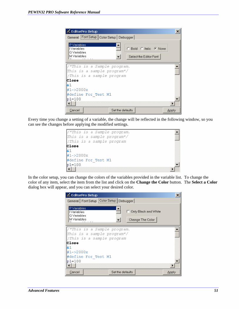
PEWIN32 PRO Software Reference Manual
Every time you change a setting of a variable, the change will be reflected in the following window, so you can see the changes before applying the modified settings.
In the color setup, you can change the colors of the variables provided in the variable list. To change the color of any item, select the item from the list and click on the Change the Color button. The Select a Color dialog box will appear, and you can select your desired color.
Advanced Features 51
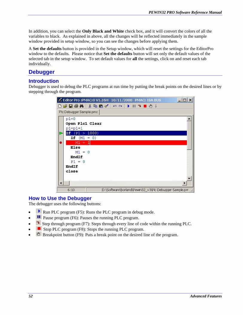
PEWIN32 PRO Software Reference Manual
In addition, you can select the Only Black and White check box, and it will convert the colors of all the variables to black. As explained in above, all the changes will be reflected immediately in the sample window provided in setup window, so you can see the changes before applying them.
A Set the defaults button is provided in the Setup window, which will reset the settings for the EditorPro window to the defaults. Please notice that Set the defaults button will set only the default values of the selected tab in the setup window. To set default values for all the settings, click on and reset each tab individually.
Debugger Introduction Debugger is used to debug the PLC programs at run time by putting the break points on the desired lines or by stepping through the program.
How to Use the Debugger The debugger uses the following buttons:
• Run PLC program (F5): Runs the PLC program in debug mode. • Pause program (F6): Pauses the running PLC program. • Step through program (F7): Steps through every line of code within the running PLC. • Stop PLC program (F8): Stops the running PLC program. • Breakpoint button (F9): Puts a break point on the desired line of the program.
52 Advanced Features
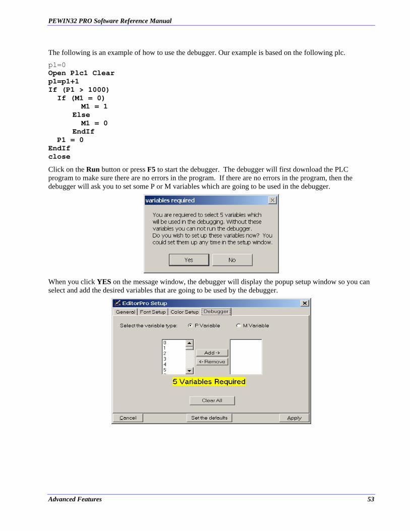
PEWIN32 PRO Software Reference Manual
The following is an example of how to use the debugger. Our example is based on the following plc. p1=0 Open Plc1 Clear p1=p1+1 If (P1 > 1000) If (M1 = 0) M1 = 1 Else M1 = 0 EndIf P1 = 0 EndIf close Click on the Run button or press F5 to start the debugger. The debugger will first download the PLC program to make sure there are no errors in the program. If there are no errors in the program, then the debugger will ask you to set some P or M variables which are going to be used in the debugger.
When you click YES on the message window, the debugger will display the popup setup window so you can select and add the desired variables that are going to be used by the debugger.
Advanced Features 53
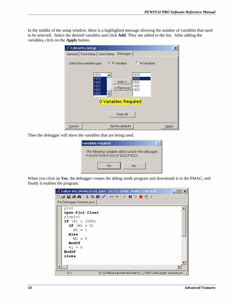
PEWIN32 PRO Software Reference Manual
In the middle of the setup window, there is a highlighted message showing the number of variables that need to be selected. Select the desired variables and click Add. They are added to the list. After adding the variables, click on the Apply button.
Then the debugger will show the variables that are being used.
When you click on Yes, the debugger creates the debug mode program and downloads it to the PMAC; and finally it enables the program.
54 Advanced Features

PEWIN32 PRO Software Reference Manual
To Pause through the program, click on the Pause button (F6). By clicking on this button, the line that the PMAC is running in the program will be highlighted. To go to the next line that PMAC will execute, click on the Step button (F7). PMAC will execute a line with every click of the Step button.
You could also put a breakpoint on any line of the program. The program will stop on any line containing a breakpoint. To put the breakpoint on a line, click on that line and click on the Breakpoint button (F9).
Advanced Features 55
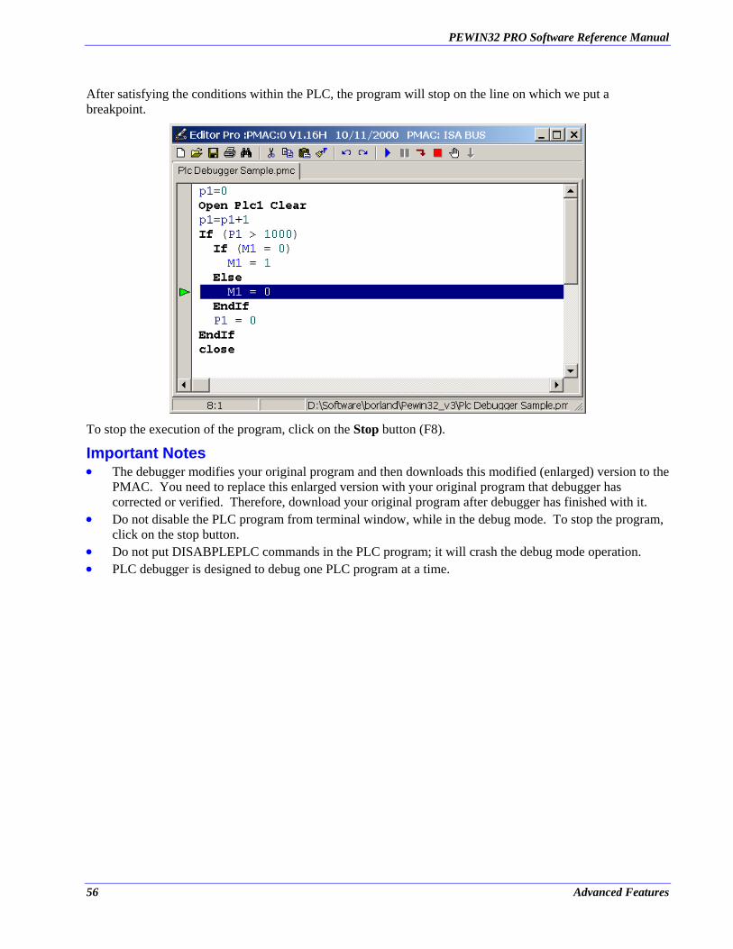
PEWIN32 PRO Software Reference Manual
After satisfying the conditions within the PLC, the program will stop on the line on which we put a breakpoint.
To stop the execution of the program, click on the Stop button (F8).
Important Notes •
•
• •
The debugger modifies your original program and then downloads this modified (enlarged) version to the PMAC. You need to replace this enlarged version with your original program that debugger has corrected or verified. Therefore, download your original program after debugger has finished with it. Do not disable the PLC program from terminal window, while in the debug mode. To stop the program, click on the stop button. Do not put DISABPLEPLC commands in the PLC program; it will crash the debug mode operation. PLC debugger is designed to debug one PLC program at a time.
56 Advanced Features
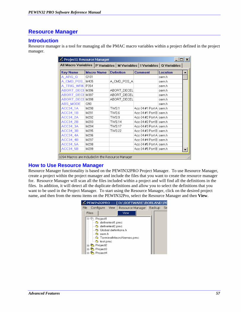
PEWIN32 PRO Software Reference Manual
Resource Manager Introduction Resource manager is a tool for managing all the PMAC macro variables within a project defined in the project manager.
How to Use Resource Manager Resource Manager functionality is based on the PEWIN32PRO Project Manager. To use Resource Manager, create a project within the project manager and include the files that you want to create the resource manager for. Resource Manager will scan all the files included within a project and will find all the definitions in the files. In addition, it will detect all the duplicate definitions and allow you to select the definitions that you want to be used in the Project Manager. To start using the Resource Manager, click on the desired project name, and then from the menu items on the PEWIN32Pro, select the Resource Manager and then View.
Advanced Features 57
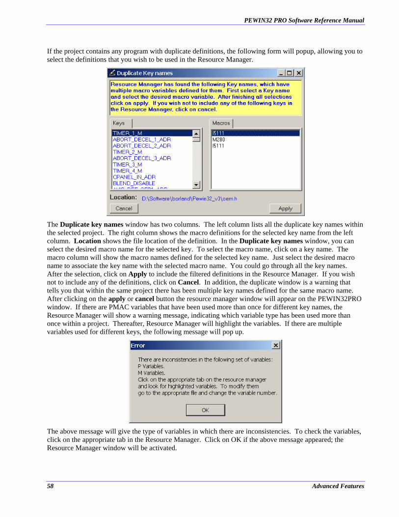
PEWIN32 PRO Software Reference Manual
If the project contains any program with duplicate definitions, the following form will popup, allowing you to select the definitions that you wish to be used in the Resource Manager.
The Duplicate key names window has two columns. The left column lists all the duplicate key names within the selected project. The right column shows the macro definitions for the selected key name from the left column. Location shows the file location of the definition. In the Duplicate key names window, you can select the desired macro name for the selected key. To select the macro name, click on a key name. The macro column will show the macro names defined for the selected key name. Just select the desired macro name to associate the key name with the selected macro name. You could go through all the key names. After the selection, click on Apply to include the filtered definitions in the Resource Manager. If you wish not to include any of the definitions, click on Cancel. In addition, the duplicate window is a warning that tells you that within the same project there has been multiple key names defined for the same macro name. After clicking on the apply or cancel button the resource manager window will appear on the PEWIN32PRO window. If there are PMAC variables that have been used more than once for different key names, the Resource Manager will show a warning message, indicating which variable type has been used more than once within a project. Thereafter, Resource Manager will highlight the variables. If there are multiple variables used for different keys, the following message will pop up.
The above message will give the type of variables in which there are inconsistencies. To check the variables, click on the appropriate tab in the Resource Manager. Click on OK if the above message appeared; the Resource Manager window will be activated.
58 Advanced Features
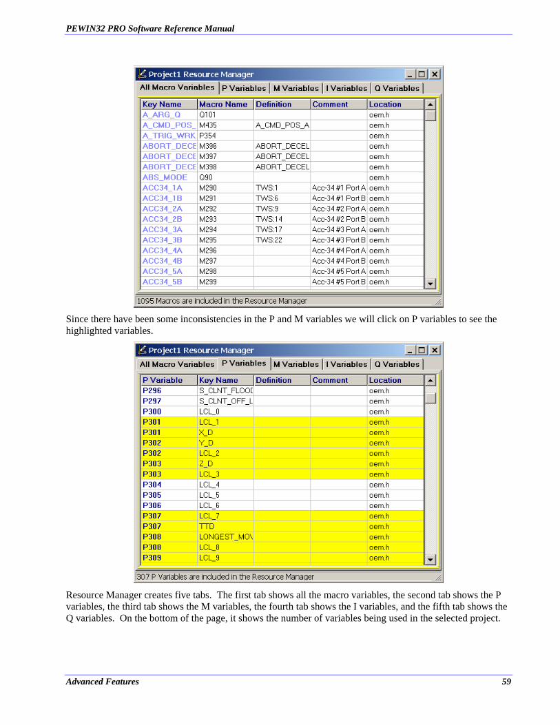
PEWIN32 PRO Software Reference Manual
Since there have been some inconsistencies in the P and M variables we will click on P variables to see the highlighted variables.
Resource Manager creates five tabs. The first tab shows all the macro variables, the second tab shows the P variables, the third tab shows the M variables, the fourth tab shows the I variables, and the fifth tab shows the Q variables. On the bottom of the page, it shows the number of variables being used in the selected project.
Advanced Features 59
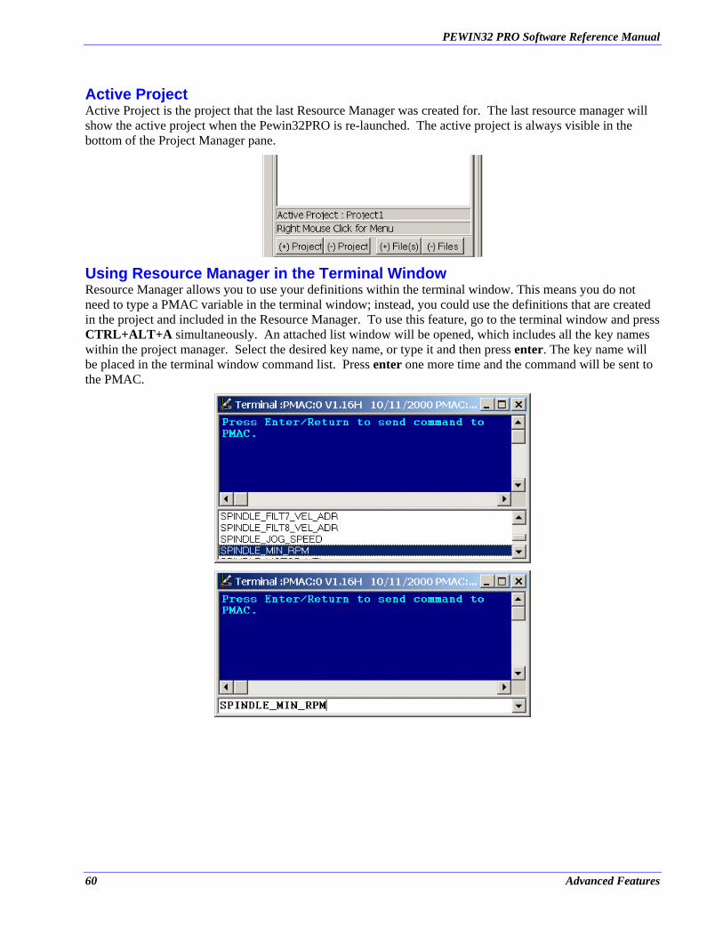
PEWIN32 PRO Software Reference Manual
Active Project Active Project is the project that the last Resource Manager was created for. The last resource manager will show the active project when the Pewin32PRO is re-launched. The active project is always visible in the bottom of the Project Manager pane.
Using Resource Manager in the Terminal Window Resource Manager allows you to use your definitions within the terminal window. This means you do not need to type a PMAC variable in the terminal window; instead, you could use the definitions that are created in the project and included in the Resource Manager. To use this feature, go to the terminal window and press CTRL+ALT+A simultaneously. An attached list window will be opened, which includes all the key names within the project manager. Select the desired key name, or type it and then press enter. The key name will be placed in the terminal window command list. Press enter one more time and the command will be sent to the PMAC.
60 Advanced Features
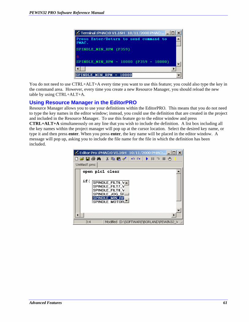
PEWIN32 PRO Software Reference Manual
You do not need to use CTRL+ALT+A every time you want to use this feature; you could also type the key in the command area. However, every time you create a new Resource Manager, you should reload the new table by using CTRL+ALT+A.
Using Resource Manager in the EditorPRO Resource Manager allows you to use your definitions within the EditorPRO. This means that you do not need to type the key names in the editor window; instead, you could use the definition that are created in the project and included in the Resource Manager. To use this feature go to the editor window and press CTRL+ALT+A simultaneously on any line that you wish to include the definition. A list box including all the key names within the project manager will pop up at the cursor location. Select the desired key name, or type it and then press enter. When you press enter, the key name will be placed in the editor window. A message will pop up, asking you to include the file name for the file in which the definition has been included.
Advanced Features 61
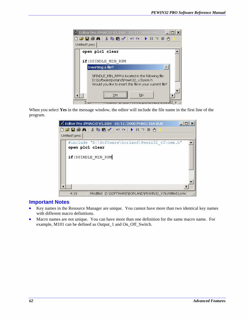
PEWIN32 PRO Software Reference Manual
When you select Yes in the message window, the editor will include the file name in the first line of the program.
Important Notes •
•
Key names in the Resource Manager are unique. You cannot have more than two identical key names with different macro definitions. Macro names are not unique. You can have more than one definition for the same macro name. For example, M101 can be defined as Output_1 and On_Off_Switch.
62 Advanced Features
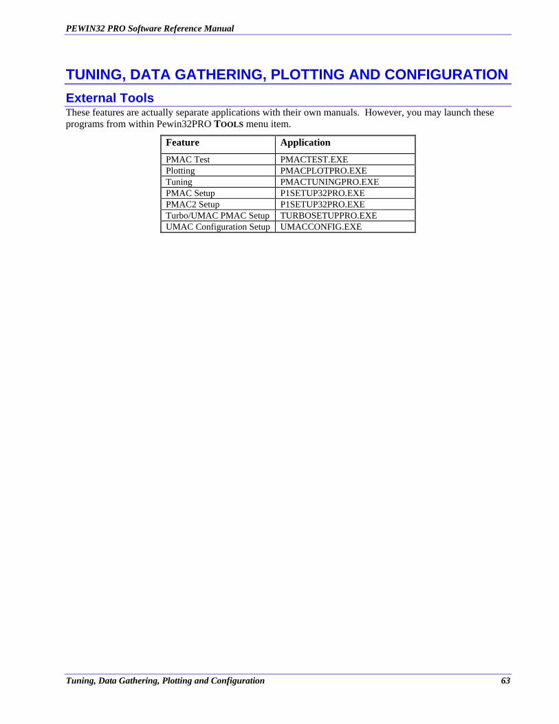
PEWIN32 PRO Software Reference Manual
TUNING, DATA GATHERING, PLOTTING AND CONFIGURATION External Tools These features are actually separate applications with their own manuals. However, you may launch these programs from within Pewin32PRO TOOLS menu item.
Feature Application
PMAC Test PMACTEST.EXE Plotting PMACPLOTPRO.EXE Tuning PMACTUNINGPRO.EXE PMAC Setup P1SETUP32PRO.EXE PMAC2 Setup P1SETUP32PRO.EXE Turbo/UMAC PMAC Setup TURBOSETUPPRO.EXE UMAC Configuration Setup UMACCONFIG.EXE
Tuning, Data Gathering, Plotting and Configuration 63

PEWIN32 PRO Software Reference Manual
64 Tuning, Data Gathering, Plotting and Configuration
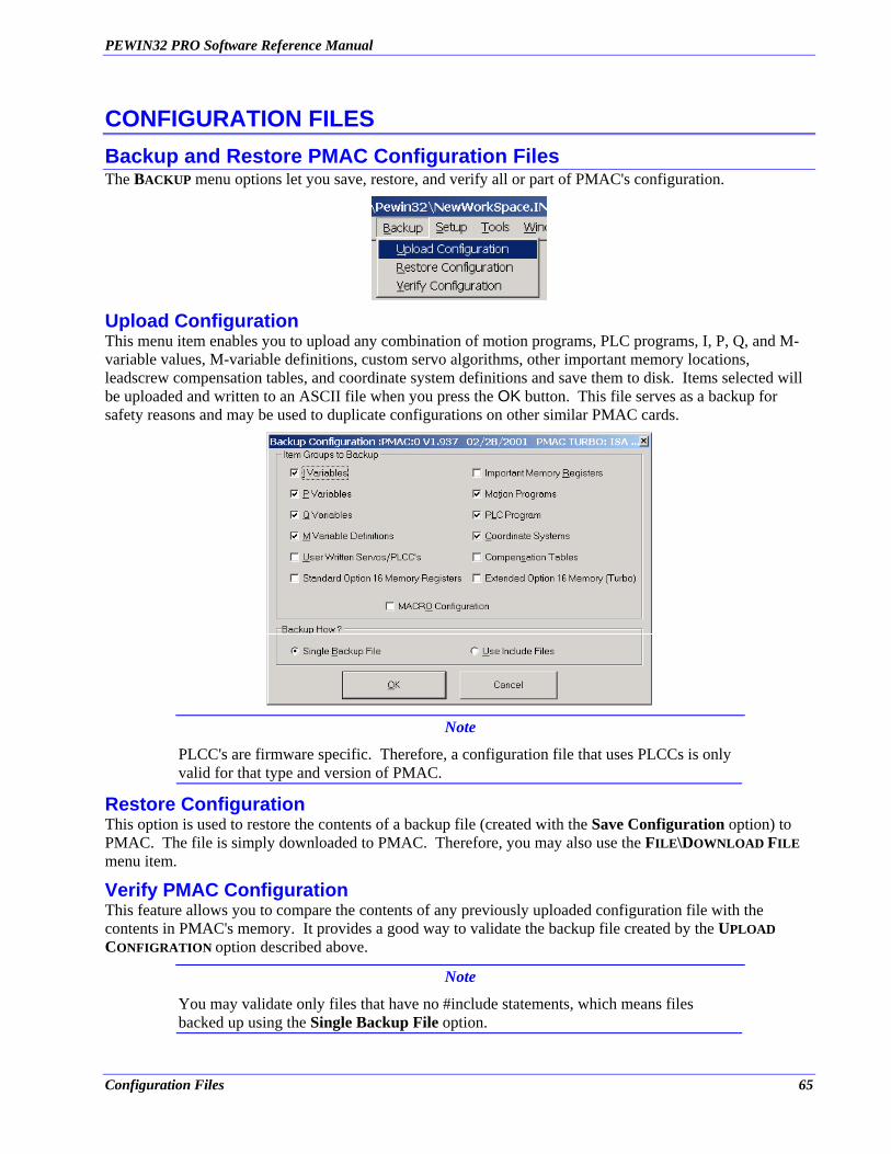
PEWIN32 PRO Software Reference Manual
CONFIGURATION FILES Backup and Restore PMAC Configuration Files The BACKUP menu options let you save, restore, and verify all or part of PMAC's configuration.
Upload Configuration This menu item enables you to upload any combination of motion programs, PLC programs, I, P, Q, and M-variable values, M-variable definitions, custom servo algorithms, other important memory locations, leadscrew compensation tables, and coordinate system definitions and save them to disk. Items selected will be uploaded and written to an ASCII file when you press the OK button. This file serves as a backup for safety reasons and may be used to duplicate configurations on other similar PMAC cards.
Note
PLCC's are firmware specific. Therefore, a configuration file that uses PLCCs is only valid for that type and version of PMAC.
Restore Configuration This option is used to restore the contents of a backup file (created with the Save Configuration option) to PMAC. The file is simply downloaded to PMAC. Therefore, you may also use the FILE\DOWNLOAD FILE menu item.
Verify PMAC Configuration This feature allows you to compare the contents of any previously uploaded configuration file with the contents in PMAC's memory. It provides a good way to validate the backup file created by the UPLOAD CONFIGRATION option described above.
Note
You may validate only files that have no #include statements, which means files backed up using the Single Backup File option.
Configuration Files 65

PEWIN32 PRO Software Reference Manual
66 Configuration Files
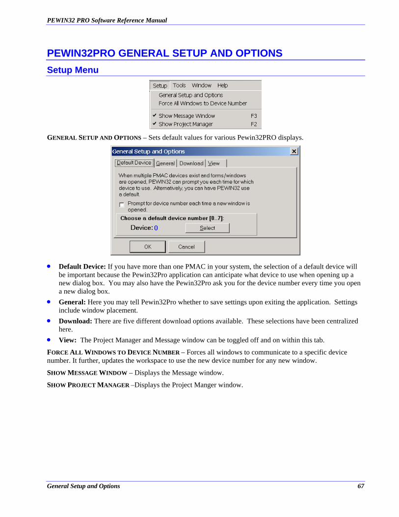
PEWIN32 PRO Software Reference Manual
PEWIN32PRO GENERAL SETUP AND OPTIONS Setup Menu
GENERAL SETUP AND OPTIONS – Sets default values for various Pewin32PRO displays.
•
•
•
•
Default Device: If you have more than one PMAC in your system, the selection of a default device will be important because the Pewin32Pro application can anticipate what device to use when opening up a new dialog box. You may also have the Pewin32Pro ask you for the device number every time you open a new dialog box. General: Here you may tell Pewin32Pro whether to save settings upon exiting the application. Settings include window placement. Download: There are five different download options available. These selections have been centralized here. View: The Project Manager and Message window can be toggled off and on within this tab.
FORCE ALL WINDOWS TO DEVICE NUMBER – Forces all windows to communicate to a specific device number. It further, updates the workspace to use the new device number for any new window.
SHOW MESSAGE WINDOW – Displays the Message window.
SHOW PROJECT MANAGER –Displays the Project Manger window.
General Setup and Options 67

PEWIN32 PRO Software Reference Manual
68 General Setup and Options
PEWIN32 PRO Software Reference Manual
PEWIN32PRO HELP Pewin32Pro Manual From the help menu choose contents to view this document in help format. Alternatively, pressing F1 will do the same in addition to locating context sensitive information.
Driver Installation Notes This Adobe Acrobat format document provides details of all driver installations and is a great tool for troubleshooting any communication or other configuration issues. It gives a detailed procedure for Firmware downloads.
Why am I Not Moving? This menu choice can save you many hours of searching and frustration in tracking down problems associated with running a motor – especially if you are new to PMAC. You may run into a condition in which a motor simply will not run, despite you're being sure that all the parameters have been set properly. This menu option will look at your configuration and cite possible (warnings) or definite causes of problems preventing you from running your motor(s). To use this self-diagnostic feature, you must specify a particular motor.
Why is my Program Not Running? This menu choice can also save you many hours of searching and frustration in tracking down problems associated with running the program. You may run into the condition in which a program simply will not run, despite you're being sure that all the parameters have been set properly. This menu option looks at your configuration, and cites possible or definite causes of problems preventing you from running your motion program(s). To use this self-diagnostic feature, you must specify a particular coordinate system.
Help 69

PEWIN32 PRO Software Reference Manual
70 Help
PEWIN32 PRO Software Reference Manual
APPENDIX A - UNDERSTANDING PMAC’S WATCHDOG TIMER PMAC’s Watchdog Timer The PMAC motion control board has an on-board "watchdog timer" (sometimes called a "dead-man timer" or a "get-lost timer") circuit whose job it is to detect a number of conditions that could result in dangerous malfunction, and shut down the card to prevent a malfunction. The philosophy behind the use of this circuit is that it is safer to have the system not operate at all than to have it operate improperly.
Because the watchdog timer "wants" to fail, and many components of the board, both hardware and software, must be working properly to keep it from failing, it may not be immediately obvious what the cause of a watchdog timer failure is. This application note is a guide to examining the possible causes of watchdog failure.
How the Watchdog Timer Works The hardware circuit for the watchdog timer requires that two basic conditions be met to keep it from tripping. First, it must see a DC voltage greater than approximately 4.75V. If the supply voltage is below this value, the circuit's relay will trip. This prevents corruption of registers due to insufficient voltage. The second necessary condition is that the timer must see a square wave input (provided by the PMAC software) of a frequency greater than approximately 25 Hz. If the card, for whatever reason, due either to hardware or software problems, cannot set and clear this bit repeatedly at this frequency or higher, the circuit's relay will trip.
In the PMAC software, the task that actually writes to the watchdog timer is called the "real-time interrupt" (RTI). This task is supposed to execute at a fixed number of servo cycles. The number of servo cycles is determined by variable I8 – the RTI executes every I8+1 servo cycles. At the default value of 2, this is every third servo cycle. The servo cycle frequency is divided from the master clock by an amount determined by the settings of jumpers E98, E29-E33, and E3-E6. At the default settings, the servo frequency is 2.25 kHz, so the default RTI frequency is 750 Hz. If the RTI frequency were to drop below about 50 Hz, it could not provide the 25 Hz square wave, and the timer would trip. With the default servo update rate, an I8 value greater than about 30 will cause the timer to trip.
Every RTI, PMAC reads the 12-bit watchdog timer register (Y register $1F) and decrements the value by 8 –this toggles bit 3. If the resulting value is not less than zero, it copies the result into a register that forces the bit 3 value onto the watchdog timer. Repeated, this process provides a square-wave input to the watchdog timer.
If no other task intervened, the RTI would stop toggling the watchdog input after 512 cycles (212/8), because the timer register would have counted down to zero. The task that keeps this from happening is the "housekeeping" function in PMAC's background tasks. The background tasks execute in the time available between higher priority tasks such as servo cycle updates, and RTI tasks. The three main background tasks are responding to host commands, executing PLC programs (1-31), and housekeeping. In the background, PMAC executes one scan through an individual PLC program, then checks to see if there are any complete commands, responding if there are, then executes the housekeeping functions. This cycle is repeatedly endlessly.
Most of the housekeeping functions are safety checks such as following error limits and over-travel limits. When it is done with these checks, PMAC sets the 12-bit watchdog timer register back to its maximum value. As long as this occurs regularly at least every 512 RTI cycles, the watchdog timer will not trip.
The purpose of this two-part control of the timer is to make sure all aspects of the PMAC software are being executed, both in foreground (interrupt-driven) and background. If anything keeps either type of routine from executing, the watchdog will fail quickly.
Appendix B 71
PEWIN32 PRO Software Reference Manual
What to Look for When the Timer Trips The things that can trip the watchdog timer can be divided into four basic classes: constant (or quickly repeatable) hardware problems, intermittent hardware problems, constant (or quickly repeatable) software problems, or intermittent software problems. The following procedure should help you determine which type of problem it is.
If you think the watchdog timer has tripped – this is usually suspected when the outputs all turn off and communications to the host is lost – check the LEDs on PMAC. If both the red and green LEDs are on, the watchdog timer has tripped. If both LEDs are off, you have lost all 5V power to the card. If the green LED is on, and the red LED is off, the watchdog timer has not tripped; there is some other problem.
If the watchdog timer has tripped, reset the card either by taking the INIT/ line on the control panel connector low, then high, or by cycling power. If the red LED stays lit after the reset, you have a constant problem; if it goes off, you have an intermittent problem.
Constant Problem: If the red LED stays lit on reset, you must determine whether the constant problem is in hardware or software. The best way to determine this is to turn the power off, change jumper E51 from its default state (take OFF for PMAC-STD, put ON for all others), then turn power back on. This re-initializes PMAC, disabling all software settings and programs that could have tripped the timer. If the red LED stays on, you have a constant hardware problem; if it goes off, you have (or at least had) a constant software problem.
Note
Re-initializing the card works by installing the factory-default I-variable values, instead of the values stored in EPROM. You do not lose the values you have stored in EPROM (unless you SAVE the default values); you simply are not using them. If you fix the hardware or jumper setting problem that was causing the watchdog trip, you can recover your old values simply by powering up the card with E51 in its default state.
Constant Hardware Problem: There are several possible causes of a constant hardware problem. The first is low supply voltage. With a voltmeter, probe between +5V and GND on one of the connectors at the card -- for example, between pins 1 and 3 on the machine connector. If you suspect variation in the supply, you may want to use an oscilloscope to catch changes.
If the supply looks OK, you will want to inspect the card itself. Turn off power and remove the card. If there are several circuit boards, make sure that the daughter boards are well seated on the motherboard. Look at all the socketed ICs. Make sure that they are firmly in their sockets, with no bent or broken legs. Apply reasonable pressure to each socketed IC. Re-install the card and turn on power.
If the red LED is still on, turn off power and remove the card again. Check the board thoroughly for signs of damage: broken components, damaged circuit board, cracked solder joints, etc. Any of these types of problems will require a factory repair.
Constant Software Problem: If using the re-initialization jumper setting on E51 allows the card to power up without tripping the watchdog timer, the problem that caused the tripping was in software, almost always caused by a particular software function taking too much of the processor's time. Now you must determine which function is causing the problem.
PMAC requires at least 55 microseconds in the servo update time per activated motor. If you have too many active motors and a fast servo update time, you may starve the lower-priority tasks, including watchdog update, for time, and shut down the clock. At the default update rate of 2.25 kHz, it is possible to have all 8 motors active. When the card is re-initialized, only motor 1 is left activated (I100=1; I200-I800=0), so the card can run successfully at any servo update rate.
72 Appendix A
PEWIN32 PRO Software Reference Manual
If you suspect that this may be the problem, check what your servo update rate is. First, calculate it from the master clock frequency and the settings of jumpers E98, E29-E33, and E3-E6. Second, confirm the frequency setting by probing with an oscilloscope the SERVO clock signal on the serial port connector. If it is true that the servo clock frequency is too fast for the number of activated motors you want, you will need to slow down the servo clock by changing jumper settings before re-activating all of your motors.
If the servo update frequency does not appear to be the problem, a PLC program probably is. Re-initialization solves this problem by setting I5 to 0, not permitting any PLC programs to run. PLC 0, which runs as an RTI task, is the most likely culprit, because it can starve the background tasks for time, preventing the housekeeping routine from resetting the timer register. If you suspect PLC 0, you can delete it now (OPEN PLC 0 CLEAR CLOSE), turn off power, change E51 back to its default setting, and turn power back on. If the watchdog does not trip, you have confirmed that the PLC 0 was the problem.
In general, PLC 0 should be kept very short, and usually the shorter the better. PMAC will execute an enabled PLC 0 every RTI, unless it has not finished the RTI tasks (PLC 0 and motion program) that it started in a previous RTI cycle. If a given PLC 0 takes 95% of the time available for it in one RTI cycle, all of the background tasks put together have to run in the remaining 5%, which may not let them keep the watchdog timer happy. Shortening the PLC 0 slightly, so that it only takes 85% of available RTI time, would allow background tasks to run 3 times faster, because they would now have 15% of available time. However, lengthening the PLC 0 slightly, so that it takes 105% of the time available in a single RTI cycle, would cause it to execute only every other RTI cycle, and leave the majority of the second cycle available for background time.
For a background PLC program (PLC 1 to 31) to cause a watchdog failure, it must be extremely long -- probably thousands of lines long, unless it has virtually no time to execute, in which case the real problem is a higher priority task. In general, however, if you have a lot of PLC code, it is better to split it up into several separate PLC programs, because other background tasks, such as communications response and safety checks, will operate more often.
Intermittent Problems: If simply resetting the card without re-initializing it causes the card to operate without immediately tripping the watchdog timer, you have an intermittent problem, in either hardware or software. As we all know from trying to show a car's problem to a mechanic, intermittent problems can be much more difficult to track down.
The key in finding an intermittent problem is identifying the pattern of failure. One of the questions to ask yourself is, "What has changed since the system worked?” Try changing things back to the way they were before you were getting the failure.
Many of the possible causes of intermittent watchdog failure are fundamentally the same as the constant-problem causes listed above, but only occurring on occasion. For example, a power supply may provide inadequate voltage only when other components draw a heavy load. An important electrical contact may fail intermittently. A PMAC program may take too much time only when it is in a particular section or logical branch.
If a failure occurs repeatedly in the same section of operation of the system, the cause is probably a software time problem (unless this section cuts the supply voltage by drawing increased load). Find out what is special about the software at this point. For instance, maybe PLC 0 had been disabled, and the watchdog tripped when PLC 0 was enabled. Alternately, maybe PLC 0 had been passing over most of its calculations because of the conditional branch it was taking, but the card failed when the condition changed.
Although it is very rare for a motion program to cause a watchdog failure, this does happen on occasion. It is important to understand how the motion program executes. When a Run command is given, and every time the actual execution of programmed moves progresses into a new move, a flag is set saying it is time to do more calculations in the motion program for that coordinate system. At the next RTI, if this flag is set,
Appendix B 73

PEWIN32 PRO Software Reference Manual
PMAC will start working through the motion program. Program calculations will continue (which means no background tasks will be executed) until one of the following conditions occurs:
1. The next move or dwell is found and calculated. 2. End of, or halt to the program (e.g. STOP) is encountered. 3. Two jumps backward in the program (from ENDWHILE or GOTO) are done. 4. A WAIT statement is encountered (usually in a WHILE loop).
If calculations stop on condition 1 or 2, the calculation flag is cleared, and will not be set again until actual motion progresses into the next move (1) or a new Run command is given (2). If calculations stop on conditions 3 or 4, the flag remains set, so calculations will resume at the next RTI. In these cases, where you have an "empty" (no-motion) loop, the motion program acts much like a PLC 0 during this period. These empty loops, which are usually used to wait for a certain condition, provide very fast response to the change in condition, but their fast repetition occupies a lot of CPU time, and can starve the background tasks for time. Particularly if several coordinate systems are executing empty loops at the same time, you can run into serious background time limitations, which can be severe enough to trip the watchdog timer.
If there are a huge number of lines of intensive calculations (e.g. 100) before any move or dwell is encountered, there can be such a long time before background calculations are resumed (more than 512 RTI cycles) it is possible to trip the watchdog timer. If this problem occurs, the calculations should be split apart with short DWELL commands to give other tasks time to execute.
74 Appendix A
PEWIN32 PRO Software Reference Manual
APPENDIX B - BUG REPORT AND FEATURE REQUEST PROCEDURE Known Bugs Under Windows 98/ME, when windows are maximized and if any one of them is closed, the remaining windows lose their borders. As of this version, a temporary remedy to this is to either cascade the windows from the windows menu or, close and reopen the affected window. A permanent solution is being investigated.
Wish List 1. Add watch for control characters such as ^P, ^B etc in the Watch window. 2. Add a custom Status screen to monitor any desired register/bit and popup message mechanism for certain
flags.
Appendix B 75

PEWIN32 PRO Software Reference Manual
76 Appendix B
PEWIN32 PRO Software Reference Manual
INDEX
#define, 15
1/T Conversion., 38
A/D Register, 40
axis definitions, 37
Conversion Summing, 42
Display Every Download, 18
Download Options, 18
Filter, 41
Hardware Manuals, 51
I variables, 32
Inc w 1/T Ext, 40
Inc w Parallel Ext, 41
Inc w/o Parallel Ext, 42
LICENSE, ii
Log File, 18
Macros, 15
Macros or Compiled PLCs, 18
Map File, 18
Modify Scaling and Units, 21
M-variables, 36
Parallel with and w/o Filter, 40
PMAC memory, 31
Restore configuration..., 47
rollover, 22
Save configuration..., 47
SHOW POS,VEL, FE, 22
SHOW VELOCITY, 22
Technical Support, 3
Time Base, 41
Triggered Time Base, 41
Verify PMAC Configuration, 48
Watch, 23
Watch Entries, 26
watchdog timer, 75
Index 77