Embed Size (px)
Citation preview
11
Space Radiation EffectsSpace Radiation Effects
TutorialTutorialE. De Donder (BIRA)E. De Donder (BIRA)
23/03/2012 at ROB23/03/2012 at ROB
www.spenvis.oma.bewww.spenvis.oma.be
22
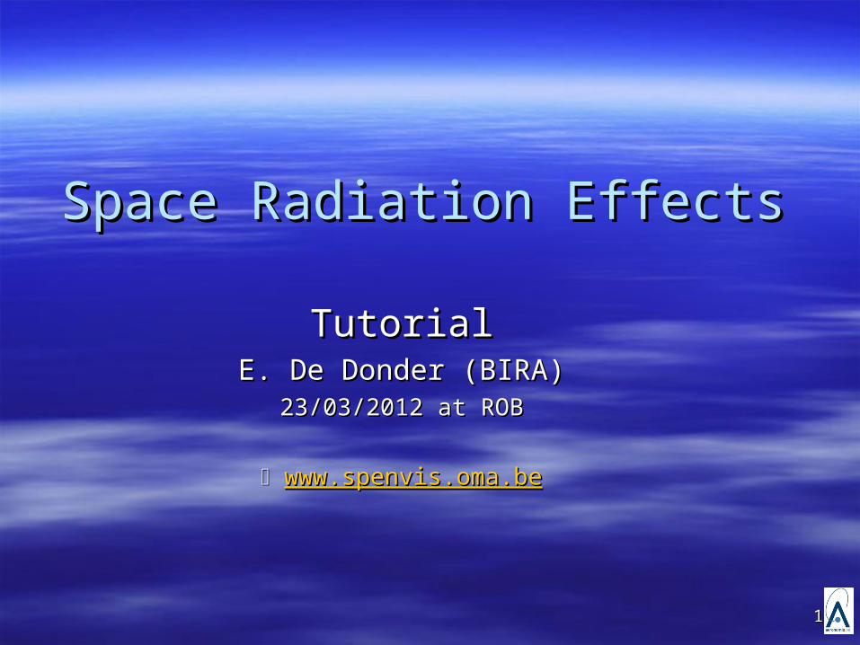
OutlineOutline
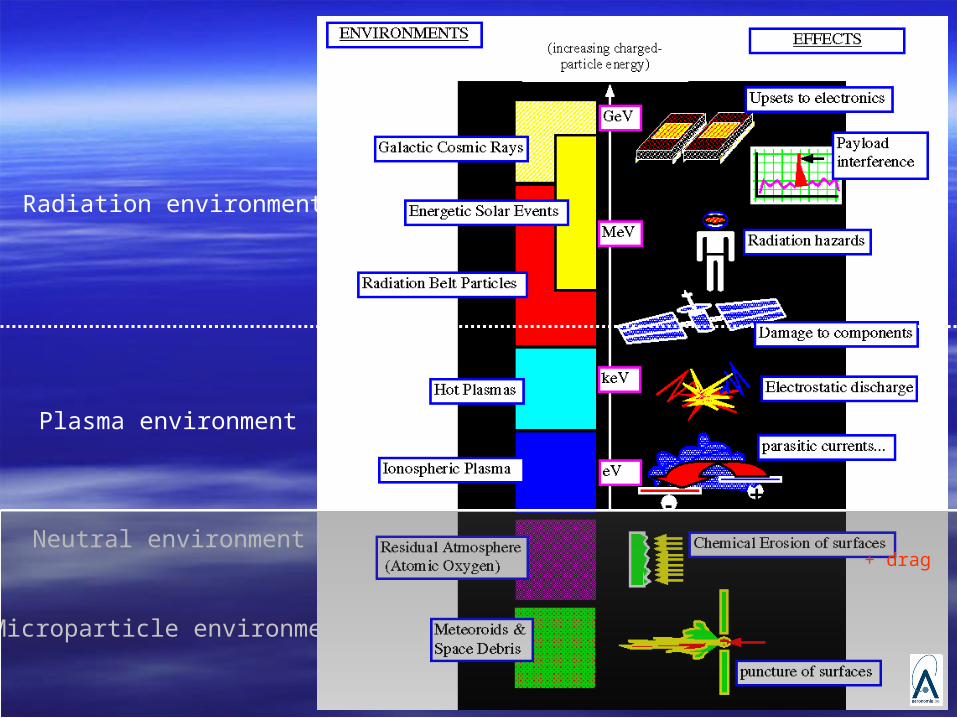
1.1. General overview pictureGeneral overview picture
2.2. Radiation environmentRadiation environment GCR particlesGCR particles Solar particlesSolar particles Trapped particlesTrapped particles Secondary particlesSecondary particles
3.3. Radiation effectsRadiation effects Total Ionizing Dose (TID)Total Ionizing Dose (TID) Displacement Damage (DDD)Displacement Damage (DDD) Single Event Effects (SEE)Single Event Effects (SEE) S/c chargingS/c charging
4.4. Solar storm threat-matrixSolar storm threat-matrix
33
Radiation environment
Plasma environment
Neutral environment
Microparticle environment
+ drag
44
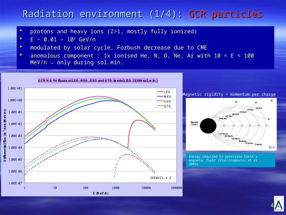
Radiation environment (1/4): Radiation environment (1/4): GCR particlesGCR particles
protons and heavy ions (Z>1, mostly fully ionized)protons and heavy ions (Z>1, mostly fully ionized) E ~ 0.01 – 10E ~ 0.01 – 1033 GeV/n GeV/n modulated by solar cycle, Forbush decrease due to CME modulated by solar cycle, Forbush decrease due to CME anomalous component : 1x ionised He, N, O, Ne, Ar with 10 < E < 100 MeV/n → only anomalous component : 1x ionised He, N, O, Ne, Ar with 10 < E < 100 MeV/n → only
during sol.min.during sol.min.
Energy required to penetrate Earth’s magnetic field (Stassinopoulos et al., 2003)
GCR H & Fe fluxes at LEO, MEO, GEO and GTO (model: ISO 15390 sol. min.)
1.00E-07
1.00E-06
1.00E-05
1.00E-04
1.00E-03
1.00E-02
1.00E-01
1.00E+00
1.00E+01
1 10 100 1000 10000 100000
E (MeV/n)
Diff
ere
ntial fl
ux
(/m
2/s
r/s/
(MeV
/n))
LEOMEOGEOGTO
Fe
H
SPENVIS-4.5
Magnetic rigidity = momentum per charge
55
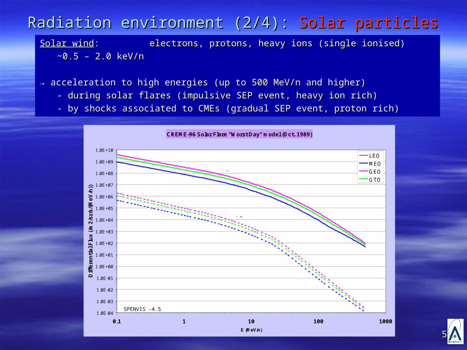
Radiation environment (2/4): Radiation environment (2/4): Solar particlesSolar particlesSolar windSolar wind: : electrons, protons, heavy ions (single ionised)electrons, protons, heavy ions (single ionised)
~0.5 – 2.0 keV/n~0.5 – 2.0 keV/n
→ → acceleration to high energies (up to 500 MeV/n and higher) acceleration to high energies (up to 500 MeV/n and higher)
- during solar flares (impulsive SEP event, heavy ion rich) - during solar flares (impulsive SEP event, heavy ion rich)
- by shocks associated to CMEs (gradual SEP event, proton rich)- by shocks associated to CMEs (gradual SEP event, proton rich)
CREME-96 Solar Flare "Worst Day" model (Oct. 1989)
1.0E-04
1.0E-03
1.0E-02
1.0E-01
1.0E+00
1.0E+01
1.0E+02
1.0E+03
1.0E+04
1.0E+05
1.0E+06
1.0E+07
1.0E+08
1.0E+09
1.0E+10
0.1 1 10 100 1000
E (MeV/n)
Diff
ere
ntial F
lux
(/m
2/s
r/s/
(MeV
/n))
LEO
MEO
GEO
GTO
H
Fe
SPENVIS -4.5
66
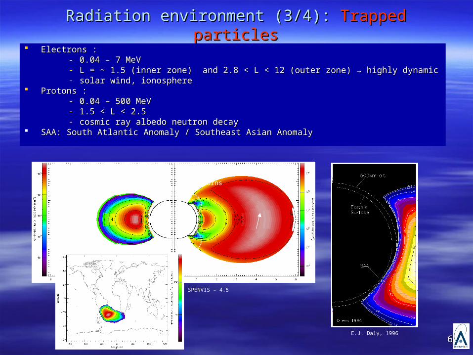
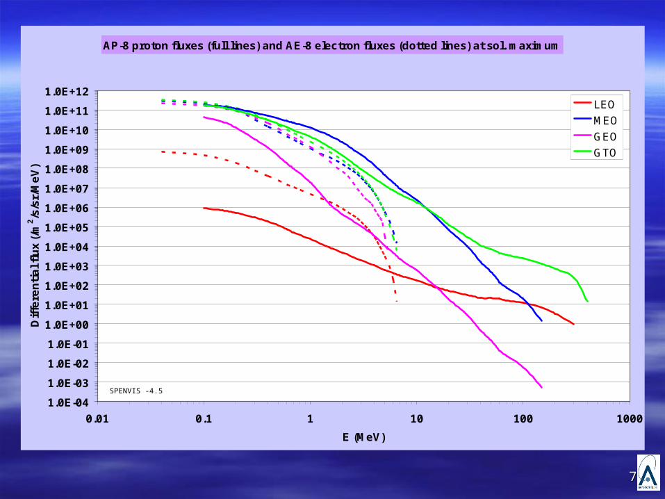
Radiation environment (3/4): Radiation environment (3/4): Trapped particlesTrapped particles Electrons : Electrons :
-- 0.04 – 7 MeV 0.04 – 7 MeV - L = ~ 1.5 (inner zone) and 2.8 < L < 12 (outer zone) → highly dynamicL = ~ 1.5 (inner zone) and 2.8 < L < 12 (outer zone) → highly dynamic- solar wind, ionospheresolar wind, ionosphere
Protons : Protons : - - 0.04 – 500 MeV 0.04 – 500 MeV - 1.5 < L < 2.5 1.5 < L < 2.5 - cosmic ray albedo neutron decaycosmic ray albedo neutron decay
SAA: South Atlantic Anomaly / Southeast Asian AnomalySAA: South Atlantic Anomaly / Southeast Asian Anomaly
Polar horns
E.J. Daly, 1996
SPENVIS – 4.5
77
AP-8 proton fluxes (full lines) and AE-8 electron fluxes (dotted lines) at sol. maximum
1.0E-04
1.0E-03
1.0E-02
1.0E-01
1.0E+00
1.0E+01
1.0E+02
1.0E+03
1.0E+04
1.0E+05
1.0E+06
1.0E+07
1.0E+08
1.0E+09
1.0E+10
1.0E+11
1.0E+12
0.01 0.1 1 10 100 1000
E (MeV)
Diff
ere
ntial fl
ux
(/m
2/s
/sr/
MeV
)
LEOMEOGEOGTO
SPENVIS -4.5
88
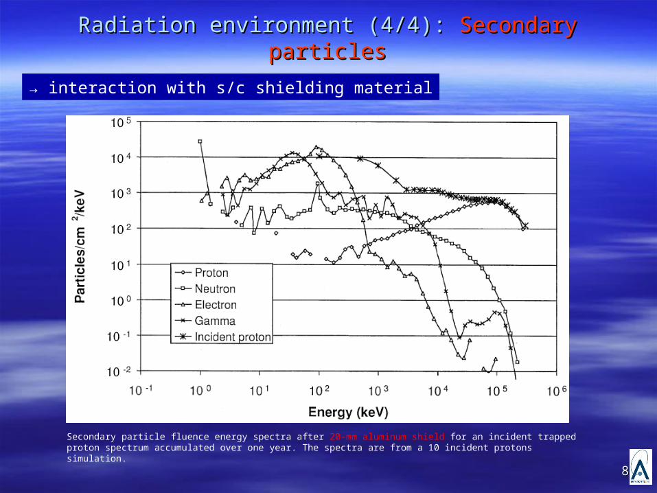
Radiation environment (4/4): Radiation environment (4/4): Secondary particlesSecondary particles
→ interaction with s/c shielding material
Secondary particle fluence energy spectra after 20-mm aluminum shield for an incident trapped proton spectrum accumulated over one year. The spectra are from a 10 incident protons simulation.
99
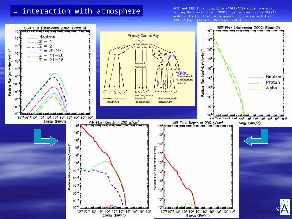
GCR and SEP flux satellite (GOES/ACE) data, observed during Halloween event 2003) propagated (with NAIRAS model) to top level atmosphere and cruise altitude (10-12 km). (from C. Mertens, 2010)
→ interaction with atmosphere
1010
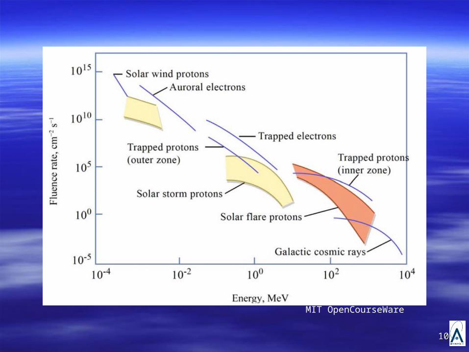
MIT OpenCourseWare
1111
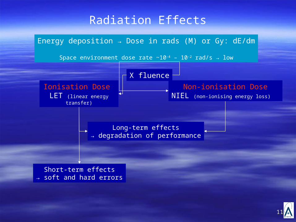
Radiation Effects
Energy deposition → Dose in rads (M) or Gy: dE/dm
Space environment dose rate ~10-4 – 10-2 rad/s → low
Long-term effects→ degradation of performance
Short-term effects→ soft and hard errors
Ionisation Dose LET (linear energy
transfer)
Non-ionisation DoseNIEL (non-ionising energy loss)
X fluence
1212
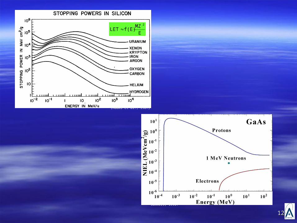
(Adams et al., 1987)
E
MZf(E)LET
2
Summers, 1993.
1313
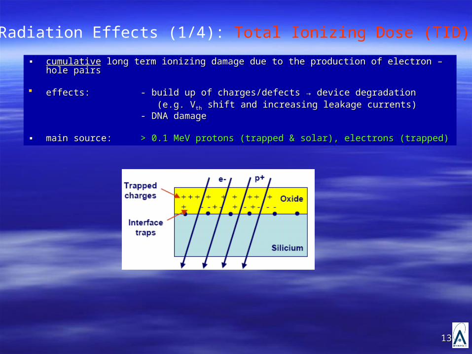
▪▪ cumulativecumulative long term ionizing damage due to the production of electron – hole pairs long term ionizing damage due to the production of electron – hole pairs
effects: effects: - build up of charges/defects → device degradation- build up of charges/defects → device degradation (e.g. V(e.g. Vthth shift and increasing leakage currents) shift and increasing leakage currents)- DNA damage- DNA damage
▪▪ mainmain source:source: > 0.1 MeV protons (trapped & solar), electrons (trapped)> 0.1 MeV protons (trapped & solar), electrons (trapped)
Radiation Effects (1/4): Total Ionizing Dose (TID)
1414
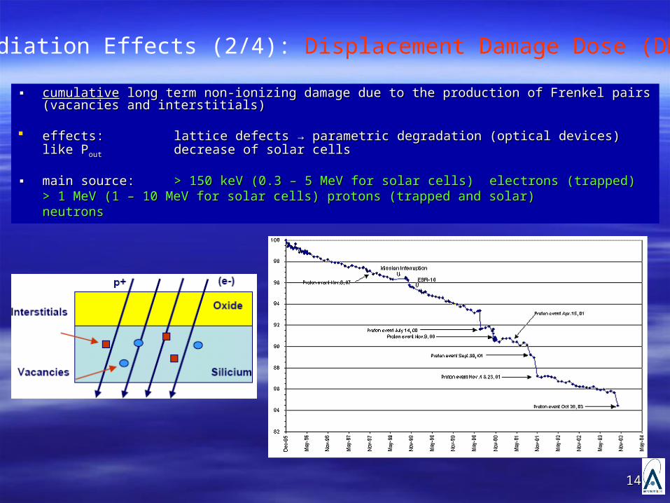
▪▪ cumulativecumulative long term non-ionizing damage due to the production of Frenkel pairs (vacancies long term non-ionizing damage due to the production of Frenkel pairs (vacancies and interstitials)and interstitials)
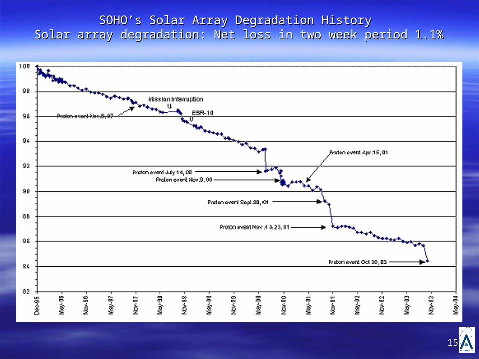
effects: effects: lattice defects → parametric degradation (optical devices) like Plattice defects → parametric degradation (optical devices) like Poutout decrease of solar cellsdecrease of solar cells
▪▪ main source: main source: > 150 keV (0.3 – 5 MeV for solar cells) electrons (trapped)> 150 keV (0.3 – 5 MeV for solar cells) electrons (trapped)> 1 MeV (1 – 10 MeV for solar cells) protons (trapped and solar)> 1 MeV (1 – 10 MeV for solar cells) protons (trapped and solar)neutronsneutrons
Radiation Effects (2/4): Displacement Damage Dose (DDD)
1515
SOHO’s Solar Array Degradation History SOHO’s Solar Array Degradation History Solar array degradation: Net loss in two week period 1.1%Solar array degradation: Net loss in two week period 1.1%
1616
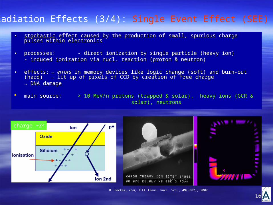
▪▪ stochasticstochastic effect caused by the production of effect caused by the production of small, spurious charge pulses within small, spurious charge pulses within electronicselectronics
▪▪ processes: processes: - direct ionization by single particle (heavy ion)- direct ionization by single particle (heavy ion)- induced ionization via nucl. reaction (proton & neutron) - induced ionization via nucl. reaction (proton & neutron)
▪ ▪ effects:effects: → → errorserrors in memory devices like logic change (soft) and burn-out (hard) in memory devices like logic change (soft) and burn-out (hard)
→ lit up of pixels of CCD by creation of free charge→ lit up of pixels of CCD by creation of free charge→ → DNA damageDNA damage
main source: main source: > 10 MeV/n protons (trapped & solar), heavy ions (GCR & > 10 MeV/n protons (trapped & solar), heavy ions (GCR & solar), neutronssolar), neutrons
Radiation Effects (3/4): Single Event Effect (SEE)
H. Becker, et al, IEEE Trans. Nucl. Sci., 49(3082), 2002
charge ~Z2
1717
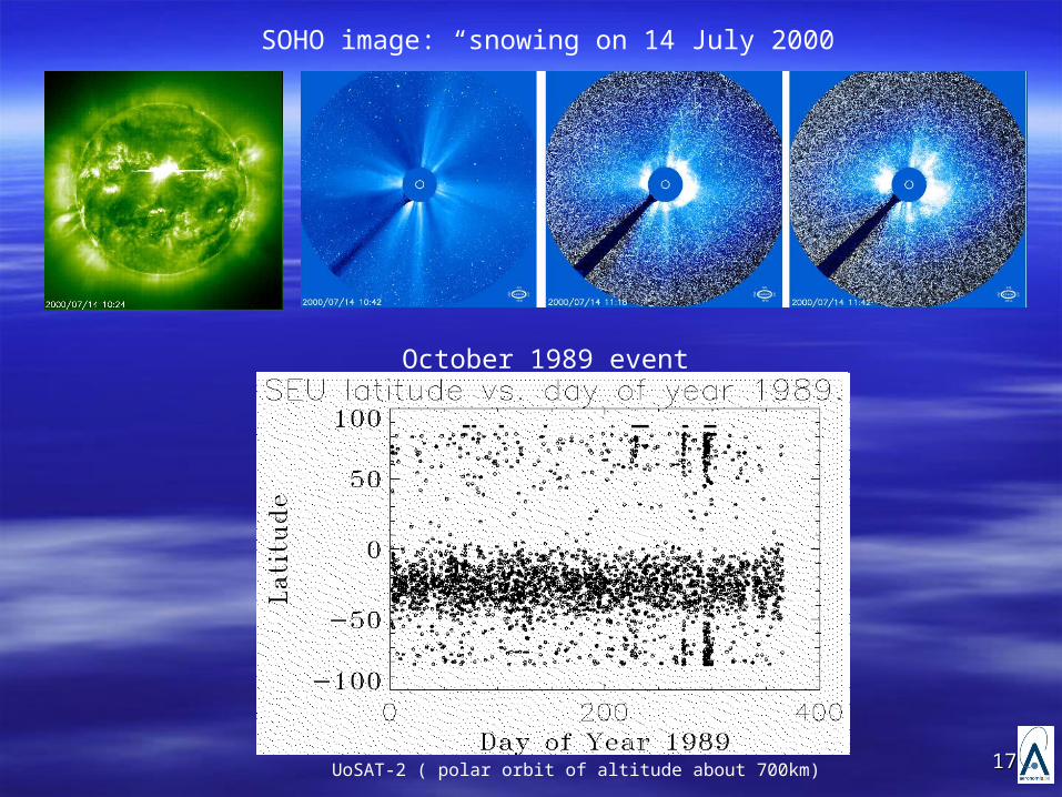
SOHO image: “snowing on 14 July 2000
October 1989 event
UoSAT-2 ( polar orbit of altitude about 700km)
1818
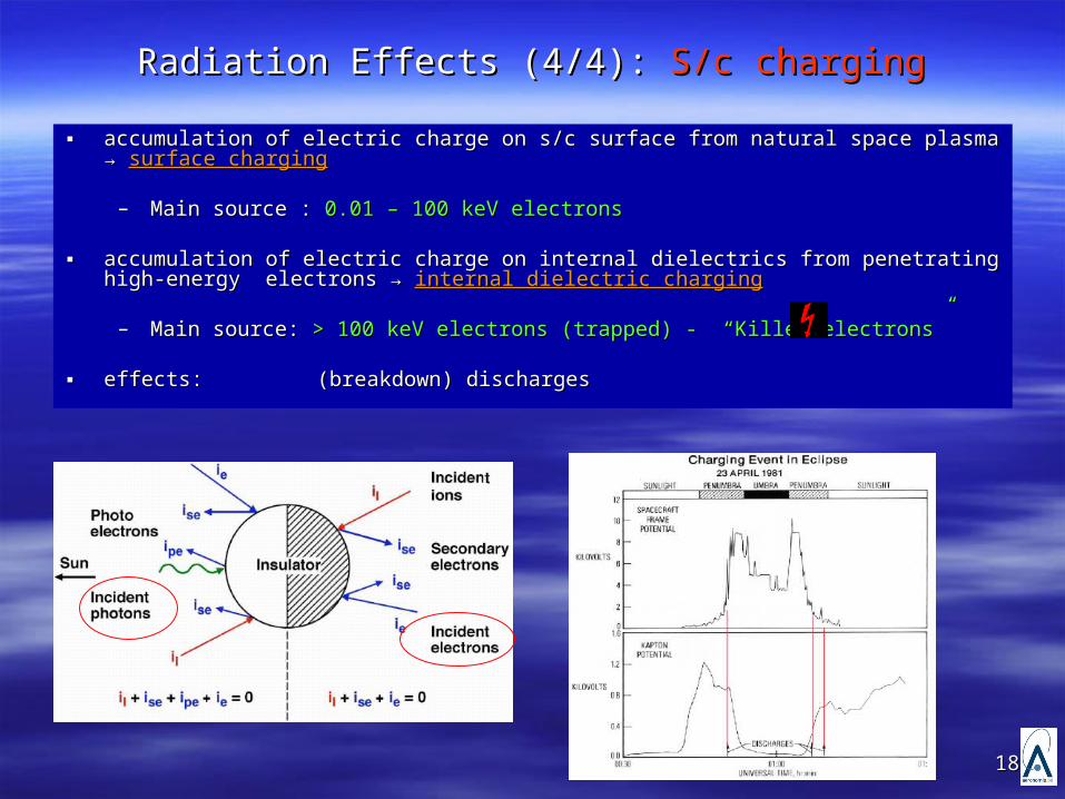
Radiation Effects (4/4): Radiation Effects (4/4): S/c chargingS/c charging
▪▪ accumulation of electric charge on s/c surface from natural space plasma → accumulation of electric charge on s/c surface from natural space plasma → surface surface chargingcharging
– Main source : Main source : 0.01 – 100 keV electrons0.01 – 100 keV electrons
▪▪ accumulation of electric charge on internal dielectrics from penetrating high-energy accumulation of electric charge on internal dielectrics from penetrating high-energy electrons → electrons → internal dielectric charginginternal dielectric charging
– Main source: Main source: > 100 keV electrons (trapped) - “Killer electrons” > 100 keV electrons (trapped) - “Killer electrons”
▪ ▪ effects: effects: (breakdown) discharges(breakdown) discharges
1919
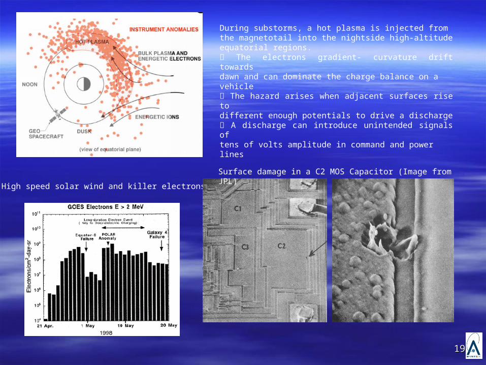
During substorms, a hot plasma is injected fromthe magnetotail into the nightside high-altitudeequatorial regions. The electrons gradient- curvature drift towardsdawn and can dominate the charge balance on avehicle The hazard arises when adjacent surfaces rise todifferent enough potentials to drive a discharge A discharge can introduce unintended signals oftens of volts amplitude in command and powerlines
High speed solar wind and killer electrons
Surface damage in a C2 MOS Capacitor (Image from JPL)
2020
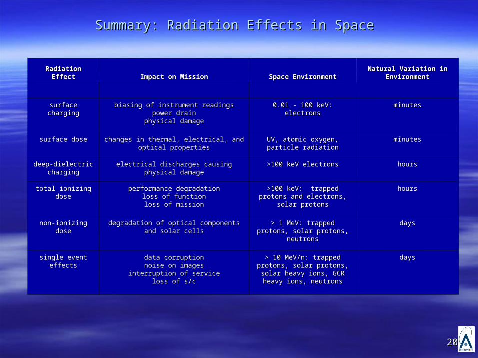
Summary: Radiation Effects in Space Summary: Radiation Effects in Space
Radiation EffectRadiation Effect Impact on MissionImpact on Mission Space EnvironmentSpace EnvironmentNatural Variation in Natural Variation in
EnvironmentEnvironment
surface chargingsurface charging biasing of instrument readingsbiasing of instrument readingspower drainpower drain
physical damagephysical damage
0.01 - 100 keV: electrons0.01 - 100 keV: electrons minutesminutes
surface dosesurface dose changes in thermal, electrical, and optical changes in thermal, electrical, and optical propertiesproperties
UV, atomic oxygen, particle UV, atomic oxygen, particle radiationradiation
minutesminutes
deep-dielectric deep-dielectric chargingcharging
electrical discharges causing physical damageelectrical discharges causing physical damage >100 keV electrons>100 keV electrons hourshours
total ionizing dosetotal ionizing dose performance degradationperformance degradationloss of functionloss of functionloss of missionloss of mission
>100 keV: trapped protons and >100 keV: trapped protons and electrons, solar protonselectrons, solar protons
hourshours
non-ionizing dosenon-ionizing dose degradation of optical components and solar degradation of optical components and solar cellscells
> 1 MeV: trapped protons, solar > 1 MeV: trapped protons, solar protons, neutronsprotons, neutrons
daysdays
single event effectssingle event effects data corruptiondata corruptionnoise on imagesnoise on images
interruption of serviceinterruption of serviceloss of s/closs of s/c
> 10 MeV/n: trapped protons, > 10 MeV/n: trapped protons, solar protons, solar heavy ions, solar protons, solar heavy ions,
GCR heavy ions, neutronsGCR heavy ions, neutrons
daysdays
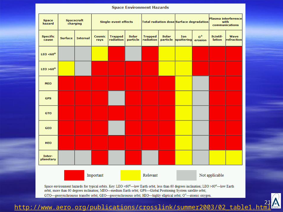
2121http://www.aero.org/publications/crosslink/summer2003/02_table1.html
2222
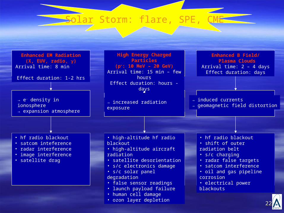
Solar Storm: flare, SPE, CME
Enhanced EM Radiation(X, EUV, radio, )
Arrival time: 8 min Effect duration: 1-2 hrs
High Energy Charged Particles
(p+: 10 MeV – 20 GeV)Arrival time: 15 min – few
hoursEffect duration: hours - days
Enhanced B Field/ Plasma Clouds
Arrival time: 2 – 4 daysEffect duration: days
• high-altitude hf radio blackout• high-altitude aircraft radiation• satellite desorientation• s/c electronics damage• s/c solar panel degradation• false sensor readings• launch payload failure• human cell damage • ozon layer depletion
• hf radio blackout• satcom inteference• radar interference• image interference• satellite drag
• hf radio blackout• shift of outer radiation belt• s/c charging• radar false targets• satcom interference• oil and gas pipeline corrosion• electrical power blackouts
→ induced currents→ geomagnetic field distortion
→ increased radiation exposure→ e- density in ionosphere→ expansion atmosphere
2323
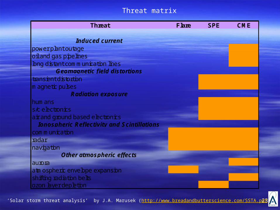
Threat Flare SPE CME
Induced currentpower plant outageoil and gas pipelineslong distant communication lines
Geomagnetic field distortionstransient distortionmagnetic pulses
Radiation exposurehumanss/c electronicsair and ground based electronics
Ionospheric Reflectivity and Scintillationscommunicationradarnavigation
Other atmospheric effectsaurora atmospheric envelope expansionshifting radiation beltsozon layer depletion
‘Solar storm threat analysis’ by J.A. Marusek (http://www.breadandbutterscience.com/SSTA.pdf)
Threat matrix
2424
References.References. E.G. Stassinopoulos et al., “A systematical global mapping of the radiation field at aviation altitudes, E.G. Stassinopoulos et al., “A systematical global mapping of the radiation field at aviation altitudes,
Space Weather, Vol. 1, No. 1, 1005, 2003.Space Weather, Vol. 1, No. 1, 1005, 2003. Adams, Jr., et al., “A comprehensive table of ion stopping powers and ranges”, NRL Memorandum Adams, Jr., et al., “A comprehensive table of ion stopping powers and ranges”, NRL Memorandum
Report, 1987.Report, 1987. June, I., et al., “Proton Nonionising Enegy Loss (NIEL) for Device applications”, June, I., et al., “Proton Nonionising Enegy Loss (NIEL) for Device applications”, IEEE Transactions on IEEE Transactions on
Nuclear Science, Vol. 50, No. 6, Dec. 2003Nuclear Science, Vol. 50, No. 6, Dec. 2003 June, I., et al., “Electron Nonionising Enegy Loss (NIEL) for Device applications”, June, I., et al., “Electron Nonionising Enegy Loss (NIEL) for Device applications”, IEEE Transactions on IEEE Transactions on
Nuclear Science, Vol. 56, No. 6, Dec. 2009Nuclear Science, Vol. 56, No. 6, Dec. 2009 C.J. Mertens et al., “C.J. Mertens et al., “Geomagnetic influence on aircraft radiation exposure during a solar energetic Geomagnetic influence on aircraft radiation exposure during a solar energetic
particle event in october 2003, Space Weather 8(S03006): doi:10.1029/2009SW000487 (2010a)particle event in october 2003, Space Weather 8(S03006): doi:10.1029/2009SW000487 (2010a) G. P. Summers, Damage Correlation in Semiconductors Exposed to Gamma, Electron, and Proton G. P. Summers, Damage Correlation in Semiconductors Exposed to Gamma, Electron, and Proton
Radiations, IEEE Trans. Nuc. Sci. 40, pp. 1300, 1993. Radiations, IEEE Trans. Nuc. Sci. 40, pp. 1300, 1993.
2525