Embed Size (px)
Citation preview
This article has been accepted for inclusion in a future issue of this journal. Content is final as presented, with the exception of pagination.
IEEE TRANSACTIONS ON SMART GRID 1
Stability of a dc Distribution System for PowerSystem Integration of Plug-In Hybrid Electric
VehiclesMansour Tabari, Student Member, IEEE, and Amirnaser Yazdani, Senior Member, IEEE
Abstract—This paper proposes a method for enhancing thestability of a dc distribution system that integrates plug-inhybrid electric vehicles (PHEVs) with an ac power grid. Thedc distribution system is interfaced with the host ac grid viaa voltage-sourced converter and can also embed photovoltaic(PV) modules. Thus, bidirectional dc–dc electronic power con-verters act as battery chargers and interface the PHEVs withthe dc distribution system, while PV modules are interfaced withthe dc distribution system via unidirectional dc–dc converters.The dc distribution system is expected to be more efficient andeconomical than a system of ac–dc battery chargers directlyinterfaced with an ac grid, but it is prone to instabilities dueto the constant-power property of the dc–dc converters. Usinga nonlinear control strategy, the proposed stability enhancementmethod mitigates the issue of instability by altering the powersetpoints of the battery chargers, bidirectional dc–dc converters,without a need for changing system parameters or hardware.The paper presents mathematical models for the original andmodified systems and demonstrates that the proposed techniqueexpands the stable operating region of the dc distribution system.Simulation results demonstrate the effectiveness of the proposedmethod for a study system in the PSCAD/EMTDC softwareenvironment.
Index Terms—Constant-power property, dc distribution sys-tem, dc grid, dc-voltage control, energy storage, plug-in hybridelectric vehicle (PHEV), smart grid, stability enhancement.
I. INTRODUCTION
THE OUTLOOK of a large number of electric vehicles,including plug-in hybrid electric vehicles (PHEVs), and
their potential impacts on the power system have motivatedmuch research recently [1], [2]. The U.S. Department ofEnergy projects that more than about one million PHEVs willhave been sold in the U.S. by 2015 and the current incentivesby the U.S. government will promote and increase the salesof PHEVs [3].
In public parking areas where a sizable number of PHEVsare interfaced with the power grid [4], such ancillary servicesas the provision of back-up power for commercial facilities,
Manuscript received November 8, 2013; revised April 9, 2014 and June 10,2014; accepted June 10, 2014. Paper no. TSG-00839-2013.
M. Tabari is with the Department of Electrical and Computer Engineering,University of Western Ontario, London, ON N6A 5B9, Canada (e-mail:[email protected]).
A. Yazdani is with the Department of Electrical and ComputerEngineering, Ryerson University, Toronto, ON M5B 2K3, Canada (e-mail:[email protected]).
Color versions of one or more of the figures in this paper are availableonline at http://ieeexplore.ieee.org.
Digital Object Identifier 10.1109/TSG.2014.2331558
voltage support [3], frequency regulation [5], peak shaving,reactive-power support [6], and integration of photovoltaic(PV) panels [7] can be offered by PHEV batteries. To providesuch services, bidirectional battery chargers must be employedto enable energy exchange between PHEVs and the host grid.
In most proposed integration strategies, ac–dc power-electronic converters act as the battery chargers and aredirectly interfaced with the power grid [8]-[9]. As a perceivedtechnically and economically superior alternative, dc distri-bution systems have recently been proposed in which dc–dcconverters act as the battery charges [10]–[14], especially forpublic areas. A dc distribution system can more efficientlyhost PV modules and interfaced with the power grid viaa central ac–dc power-electronic converter. However, due tothe constant-power property of dc–dc converters [15], [16], itbecomes unstable if the powers absorbed by the battery charg-ers exceed certain values [13]. This phenomenon inflicts alimit on the maximum power that can be imported to chargethe batteries and, consequently, precludes full utilization of theinstalled capacities and prolongs the charging times. Therefore,it is imperative to:
1) systematically characterize the phenomenon and identifythe prevailing constraints;
2) devise a stability enhancement technique, in order topush the limits and expand the stable operating regionof the dc system.
To mitigate the aforementioned issue of instabilities causedby constant-power elements in a dc distribution system, variousmethods have been proposed in the literature, [17]–[19]. Themethod proposed in [17] stabilizes a dc-link electric propulsionsystem where a dc–ac converter drives an induction motor,by altering the torque setpoint of the motor. The proposedtechnique, therefore, is applied to a dc system with one constant-power element; there is no analysis for multiple constant-powerelements. The techniques proposed in [18] and [19] deal with asystem in which a dc–dc converter is assumed to be supplyinganother constant-power element. However, both techniquesrequire information about the internal state variables and accessto the pulse width modulation (PWM) signal of the dc–dcconverter. Moreover, the studied systems include only onedc–dc converter and one constant-load element.
Expanding upon the idea proposed in [17], this paper pro-poses a control technique for expanding the stable operatingregion of a dc distribution system integrating PHEVs via bidi-rectional dc–dc converters (battery chargers), such that the dc
1949-3053 c© 2014 IEEE. Personal use is permitted, but republication/redistribution requires IEEE permission.See http://www.ieee.org/publications_standards/publications/rights/index.html for more information.
This article has been accepted for inclusion in a future issue of this journal. Content is final as presented, with the exception of pagination.
2 IEEE TRANSACTIONS ON SMART GRID
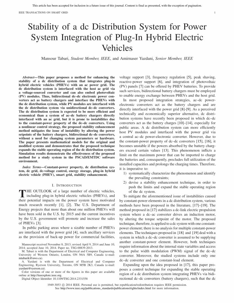
Fig. 1. dc bus for distribution of power in a parking lot for PHEVs.
system and its PHEVs can import larger powers from the hostac grid. The proposed technique is simple, does not requireinformation internal to the system or its embedded convert-ers, and does not need hardware modifications. Rather, it onlyemploys local measurements and individual power setpointsand, therefore, can be exercised in a decentralized fashion.These, in turn, permit the use of commercially available dc–dcconverters (battery chargers), expected to further reduce theoverall cost of the system. The proposed technique is alsoapplicable to other dc distribution systems, e.g., shipboardpower systems, that have multiple power-electronic converters.
II. SYSTEM CONFIGURATION
Fig. 1 illustrates a dc distribution system, for example, in aparking lot, that hosts PHEVs and PV modules. In this system,dc–dc converters are utilized as battery chargers for the PHEVsand also for interfacing the PV modules. Moreover, a centralvoltage-sourced converter (VSC) interfaces the dc distributionsystem to the host ac grid. A communication network [20] isused to enable the exchange of metering and control informa-tion for a management unit, to and from the dc–dc convertersand the central VSC. The management unit calculates the lim-its of the power exchange setpoints and sends them to thedc–dc converters, to ensure that the dc system operates in itsstable operation region. The PHEV owners, on the other hand,can set state-of-charge (SoC) limits for their vehicles, to per-mit power exchanges only if the SoC resides within a certainrange. For example, if the SoC is above 70%, then energycan be sold to the rest of the system, whereas if the SoC isbelow 40%, then the vehicle should buy energy from the restof the system. The aforementioned limits (determined basedon the trip plans, electricity price, and other factors) translateinto power setpoints for the corresponding dc–dc converters.For example, for a PHEV with 20 kWh of battery capacity, ifthe SoC limit for energy export is 70% and the present SoC is85%, then 3 kWh (that is, 15% of the battery capacity) can besold by the PHEV to the rest of the system, meaning that thepower setpoint of this particular PHEV can be set to export9 kW of power in 20 min, or 3 kW of power in 1 h, and soon [13].
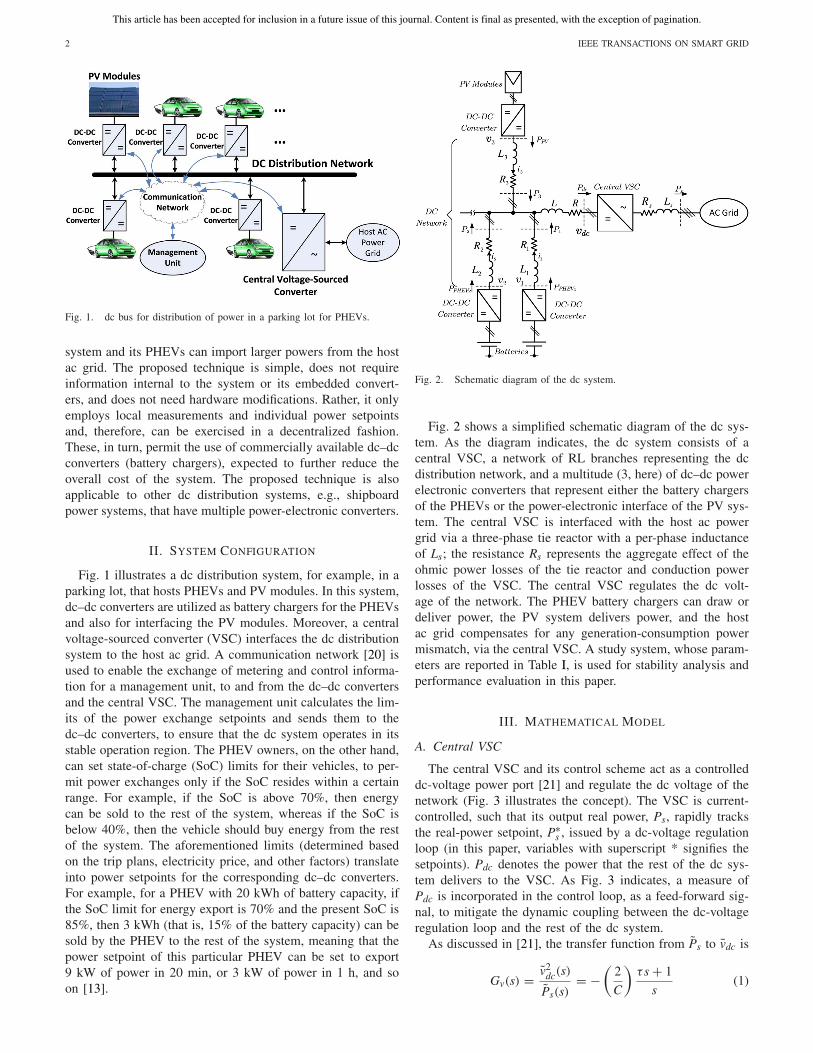
Fig. 2. Schematic diagram of the dc system.
Fig. 2 shows a simplified schematic diagram of the dc sys-tem. As the diagram indicates, the dc system consists of acentral VSC, a network of RL branches representing the dcdistribution network, and a multitude (3, here) of dc–dc powerelectronic converters that represent either the battery chargersof the PHEVs or the power-electronic interface of the PV sys-tem. The central VSC is interfaced with the host ac powergrid via a three-phase tie reactor with a per-phase inductanceof Ls; the resistance Rs represents the aggregate effect of theohmic power losses of the tie reactor and conduction powerlosses of the VSC. The central VSC regulates the dc volt-age of the network. The PHEV battery chargers can draw ordeliver power, the PV system delivers power, and the hostac grid compensates for any generation-consumption powermismatch, via the central VSC. A study system, whose param-eters are reported in Table I, is used for stability analysis andperformance evaluation in this paper.
III. MATHEMATICAL MODEL
A. Central VSC
The central VSC and its control scheme act as a controlleddc-voltage power port [21] and regulate the dc voltage of thenetwork (Fig. 3 illustrates the concept). The VSC is current-controlled, such that its output real power, Ps, rapidly tracksthe real-power setpoint, P∗
s , issued by a dc-voltage regulationloop (in this paper, variables with superscript * signifies thesetpoints). Pdc denotes the power that the rest of the dc sys-tem delivers to the VSC. As Fig. 3 indicates, a measure ofPdc is incorporated in the control loop, as a feed-forward sig-nal, to mitigate the dynamic coupling between the dc-voltageregulation loop and the rest of the dc system.
As discussed in [21], the transfer function from Ps to vdc is
Gv(s) = v2dc(s)
Ps(s)= −
(2
C
)τ s + 1
s(1)
This article has been accepted for inclusion in a future issue of this journal. Content is final as presented, with the exception of pagination.
TABARI AND YAZDANI: STABILITY OF A DC DISTRIBUTION SYSTEM FOR POWER SYSTEM INTEGRATION OF PHEVs 3
Fig. 3. Simplified block diagram of the controlled dc-voltage power port.
where the time constant τ is a function of the steady-statevalue of Pdc, i.e., Pdc0
τ = 2LsPdc 0
3V2s
(2)
where Vs is the peak value of vs, the line-to-neutral voltage ofac grid at the point of common coupling (PCC). As discussedin [21], τ is negative (corresponding to a nonminimum phaseplant) if Pdc0 is negative. Therefore, the dc-voltage regulationloop should be tuned for a case where the maximum amountof power flows from the ac grid toward the dc system to ensurestability also in other operating conditions.
In the remainder of this paper, it is assumed that the con-trolled dc-voltage power port of Fig. 3 rapidly and tightlyregulates vdc at its setpoint v∗
dc, irrespective of the steady-statevalue or transient excursions of Pdc; it is assumed that thedynamics of vdc decay to zero rapidly.
B. dc–dc Converters
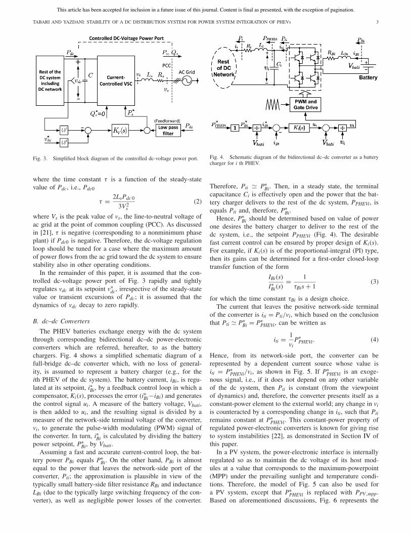
The PHEV batteries exchange energy with the dc systemthrough corresponding bidirectional dc–dc power-electronicconverters which are referred, hereafter, to as the batterychargers. Fig. 4 shows a simplified schematic diagram of afull-bridge dc–dc converter which, with no loss of general-ity, is assumed to represent a battery charger (e.g., for theith PHEV of the dc system). The battery current, iBi, is regu-lated at its setpoint, i∗Bi, by a feedback control loop in which acompensator, Ki(s), processes the error (i∗Bi−iBi) and generatesthe control signal ui. A measure of the battery voltage, Vbati,is then added to ui, and the resulting signal is divided by ameasure of the network-side terminal voltage of the converter,vi, to generate the pulse-width modulating (PWM) signal ofthe converter. In turn, i∗Bi is calculated by dividing the batterypower setpoint, P∗
Bi, by Vbati.Assuming a fast and accurate current-control loop, the bat-
tery power PBi equals P∗Bi. On the other hand, PBi is almost
equal to the power that leaves the network-side port of theconverter, Pti; the approximation is plausible in view of thetypically small battery-side filter resistance RBi and inductanceLBi (due to the typically large switching frequency of the con-verter), as well as negligible power losses of the converter.
Fig. 4. Schematic diagram of the bidirectional dc–dc converter as a batterycharger for i th PHEV.
Therefore, Pti � P∗Bi. Then, in a steady state, the terminal
capacitance Ci is effectively open and the power that the bat-tery charger delivers to the rest of the dc system, PPHEVi, isequals Pti and, therefore, P∗
Bi.Hence, P∗
Bi should be determined based on value of powerone desires the battery charger to deliver to the rest of thedc system, i.e., the setpoint PPHEVi (Fig. 4). The desirablefast current control can be ensured by proper design of Ki(s).For example, if Ki(s) is of the proportional-integral (PI) type,then its gains can be determined for a first-order closed-looptransfer function of the form
IBi(s)
I∗Bi(s)
= 1
τBis + 1(3)
for which the time constant τBi is a design choice.The current that leaves the positive network-side terminal
of the converter is iti = Pti/vi, which based on the conclusionthat Pti � P∗
Bi = P∗PHEVi, can be written as
iti = 1
viP∗
PHEVi. (4)
Hence, from its network-side port, the converter can berepresented by a dependent current source whose value isiti = P∗
PHEVi/vi, as shown in Fig. 5. If P∗PHEVi is an exoge-
nous signal, i.e., if it does not depend on any other variableof the dc system, then Pti is constant (from the viewpointof dynamics) and, therefore, the converter presents itself as aconstant-power element to the external world; any change in vi
is counteracted by a corresponding change in iti, such that Pti
remains constant at P∗PHEVi. This constant-power property of
regulated power-electronic converters is known for giving riseto system instabilities [22], as demonstrated in Section IV ofthis paper.
In a PV system, the power-electronic interface is internallyregulated so as to maintain the dc voltage of its host mod-ules at a value that corresponds to the maximum-powerpoint(MPP) under the prevailing sunlight and temperature condi-tions. Therefore, the model of Fig. 5 can also be used fora PV system, except that P∗
PHEVi is replaced with PPV,mpp.Based on aforementioned discussions, Fig. 6 represents the
This article has been accepted for inclusion in a future issue of this journal. Content is final as presented, with the exception of pagination.
4 IEEE TRANSACTIONS ON SMART GRID
Fig. 5. Simplified model of the dc–dc converter.
Fig. 6. Equivalent circuit for the analysis of the dc system of Fig. 2.
equivalent circuit of the dc system of Fig. 2; P∗PHEVi repre-
sents the power exchange setpoint of the ith battery charger,and PPV,mpp signifies the maximum power of a PV array asimposed by the corresponding maximum powerpoint tracking(MPPT) scheme.
Based on Fig. 6, the following nonlinear differential equa-tions describe the dynamic behavior of the dc system ofFig. 2:
Ld(i1 + i2 + i3)
dt+ L1
di1dt
= v1 − vdc
−R(i1 + i2 + i3) − R1i1(5)
L1di1dt
− L2di2dt
= v1 − v2 − R1i1 + R2i2 (6)
L2di2dt
− L3di3dt
= v2 − v3 − R2i2 + R3i3 (7)
C1dv1
dt= P∗
PHEV1
v1− i1 (8)
C2dv2
dt= P∗
PHEV2
v2− i2 (9)
C3dv3
dt= PPV,mpp
v3− i3. (10)
The steady-state values of the variables of the system canbe calculated by setting the derivatives to zero in (5)–(10), andsolving the nonlinear equations for every given set of powerexchange setpoints P∗
PHEV1, P∗PHEV2, and PPV,mpp.
The linearized state-space representation of (5)–(10) can beexpressed by
x = Ax (11)
where x = [i1 i2 i3 v1 v2 v3]T is the vector of state variables,and ˜ denotes small-signal perturbation around steady-stateoperating points, and components of A can be determined
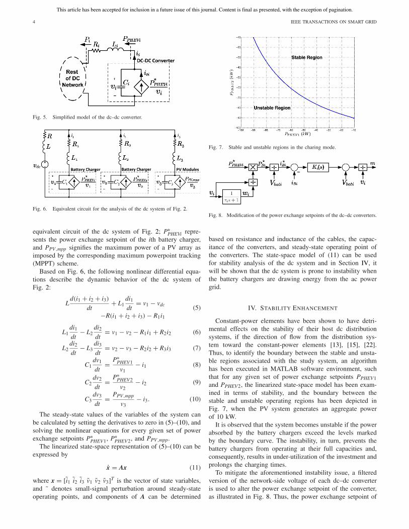
Fig. 7. Stable and unstable regions in the charing mode.
Fig. 8. Modification of the power exchange setpoints of the dc–dc converters.
based on resistance and inductance of the cables, the capac-itance of the converters, and steady-state operating point ofthe converters. The state-space model of (11) can be usedfor stability analysis of the dc system and in Section IV, itwill be shown that the dc system is prone to instability whenthe battery chargers are drawing energy from the ac powergrid.
IV. STABILITY ENHANCEMENT
Constant-power elements have been shown to have detri-mental effects on the stability of their host dc distributionsystems, if the direction of flow from the distribution sys-tem toward the constant-power elements [13], [15], [22].Thus, to identify the boundary between the stable and unsta-ble regions associated with the study system, an algorithmhas been executed in MATLAB software environment, suchthat for any given set of power exchange setpoints PPHEV1and PPHEV2, the linearized state-space model has been exam-ined in terms of stability, and the boundary between thestable and unstable operating regions has been depicted inFig. 7, when the PV system generates an aggregate powerof 10 kW.
It is observed that the system becomes unstable if the powerabsorbed by the battery chargers exceed the levels markedby the boundary curve. The instability, in turn, prevents thebattery chargers from operating at their full capacities and,consequently, results in under-utilization of the investment andprolongs the charging times.
To mitigate the aforementioned instability issue, a filteredversion of the network-side voltage of each dc–dc converteris used to alter the power exchange setpoint of the converter,as illustrated in Fig. 8. Thus, the power exchange setpoint of
This article has been accepted for inclusion in a future issue of this journal. Content is final as presented, with the exception of pagination.
TABARI AND YAZDANI: STABILITY OF A DC DISTRIBUTION SYSTEM FOR POWER SYSTEM INTEGRATION OF PHEVs 5
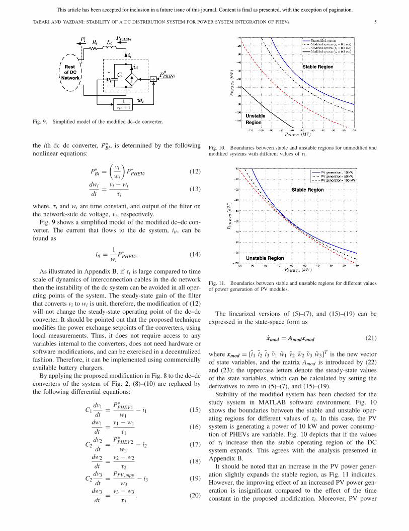
Fig. 9. Simplified model of the modified dc–dc converter.
the ith dc–dc converter, P∗Bi, is determined by the following
nonlinear equations:
P∗Bi =
(vi
wi
)P∗
PHEVi (12)
dwi
dt= vi − wi
τi(13)
where, τi and wi are time constant, and output of the filter onthe network-side dc voltage, vi, respectively.
Fig. 9 shows a simplified model of the modified dc–dc con-verter. The current that flows to the dc system, iti, can befound as
iti = 1
wiP∗
PHEVi. (14)
As illustrated in Appendix B, if τi is large compared to timescale of dynamics of interconnection cables in the dc networkthen the instability of the dc system can be avoided in all oper-ating points of the system. The steady-state gain of the filterthat converts vi to wi is unit, therefore, the modification of (12)will not change the steady-state operating point of the dc–dcconverter. It should be pointed out that the proposed techniquemodifies the power exchange setpoints of the converters, usinglocal measurements. Thus, it does not require access to anyvariables internal to the converters, does not need hardware orsoftware modifications, and can be exercised in a decentralizedfashion. Therefore, it can be implemented using commerciallyavailable battery chargers.
By applying the proposed modification in Fig. 8 to the dc–dcconverters of the system of Fig. 2, (8)–(10) are replaced bythe following differential equations:
C1dv1
dt= P∗
PHEV1
w1− i1 (15)
dw1
dt= v1 − w1
τ1(16)
C2dv2
dt= P∗
PHEV2
w2− i2 (17)
dw2
dt= v2 − w2
τ2(18)
C2dv3
dt= PPV,mpp
w3− i3 (19)
dw3
dt= v3 − w3
τ3. (20)
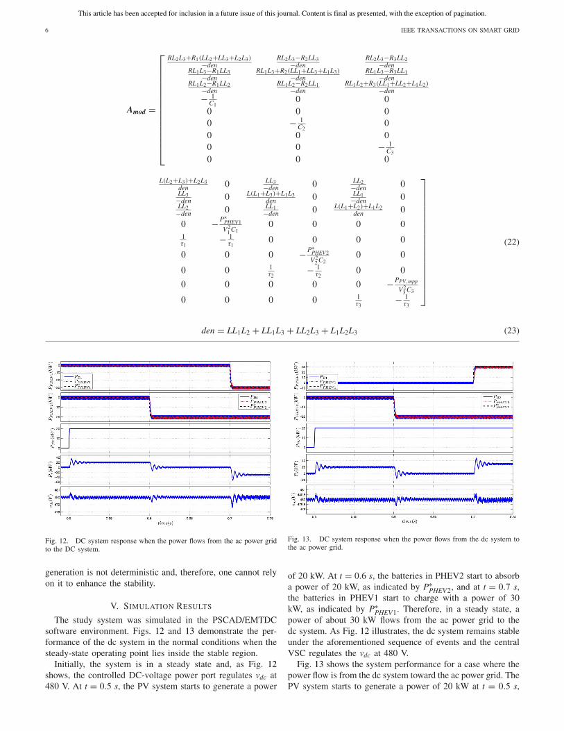
Fig. 10. Boundaries between stable and unstable regions for unmodified andmodified systems with different values of τi.
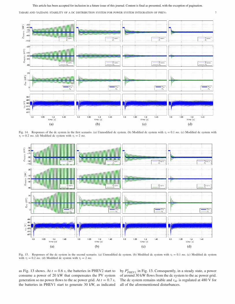
Fig. 11. Boundaries between stable and unstable regions for different valuesof power generation of PV modules.
The linearized versions of (5)–(7), and (15)–(19) can beexpressed in the state-space form as
xmod = Amodxmod (21)
where xmod = [i1 i2 i3 v1 w1 v2 w2 v3 w3]T is the new vectorof state variables, and the matrix Amod is introduced by (22)and (23); the uppercase letters denote the steady-state valuesof the state variables, which can be calculated by setting thederivatives to zero in (5)–(7), and (15)–(19).
Stability of the modified system has been checked for thestudy system in MATLAB software environment. Fig. 10shows the boundaries between the stable and unstable oper-ating regions for different values of τi. In this case, the PVsystem is generating a power of 10 kW and power consump-tion of PHEVs are variable. Fig. 10 depicts that if the valuesof τi increase then the stable operating region of the DCsystem expands. This agrees with the analysis presented inAppendix B.
It should be noted that an increase in the PV power gener-ation slightly expands the stable region, as Fig. 11 indicates.However, the improving effect of an increased PV power gen-eration is insignificant compared to the effect of the timeconstant in the proposed modification. Moreover, PV power
This article has been accepted for inclusion in a future issue of this journal. Content is final as presented, with the exception of pagination.
6 IEEE TRANSACTIONS ON SMART GRID
Amod =
⎡⎢⎢⎢⎢⎢⎢⎢⎢⎢⎢⎢⎢⎢⎢⎣
RL2L3+R1(LL2+LL3+L2L3)−denRL2L3−R2LL3−den
RL2L3−R3LL2−denRL1L3−R1LL3−den
RL1L3+R2(LL1+LL3+L1L3)−denRL1L3−R3LL1−den
RL1L2−R1LL2−denRL1L2−R2LL1−den
RL1L2+R3(LL1+LL2+L1L2)−den− 1
C10 0
0 0 00 − 1
C20
0 0 00 0 − 1
C3
0 0 0
L(L2+L3)+L2L3den 0 LL3−den 0 LL2−den 0LL3−den 0 L(L1+L3)+L1L3
den 0 LL1−den 0LL2−den 0 LL1−den 0 L(L1+L2)+L1L2
den 0
0 −P∗PHEV1V2
1 C10 0 0 0
1τ1
− 1τ1
0 0 0 0
0 0 0 −P∗PHEV2V2
2 C20 0
0 0 1τ2
− 1τ2
0 0
0 0 0 0 0 −PPV,mpp
V23 C3
0 0 0 0 1τ3
− 1τ3
⎤⎥⎥⎥⎥⎥⎥⎥⎥⎥⎥⎥⎥⎥⎥⎥⎥⎥⎦
(22)
den = LL1L2 + LL1L3 + LL2L3 + L1L2L3 (23)
Fig. 12. DC system response when the power flows from the ac power gridto the DC system.
generation is not deterministic and, therefore, one cannot relyon it to enhance the stability.
V. SIMULATION RESULTS
The study system was simulated in the PSCAD/EMTDCsoftware environment. Figs. 12 and 13 demonstrate the per-formance of the dc system in the normal conditions when thesteady-state operating point lies inside the stable region.
Initially, the system is in a steady state and, as Fig. 12shows, the controlled DC-voltage power port regulates vdc at480 V. At t = 0.5 s, the PV system starts to generate a power
Fig. 13. DC system response when the power flows from the dc system tothe ac power grid.
of 20 kW. At t = 0.6 s, the batteries in PHEV2 start to absorba power of 20 kW, as indicated by P∗
PHEV2, and at t = 0.7 s,the batteries in PHEV1 start to charge with a power of 30kW, as indicated by P∗
PHEV1. Therefore, in a steady state, apower of about 30 kW flows from the ac power grid to thedc system. As Fig. 12 illustrates, the dc system remains stableunder the aforementioned sequence of events and the centralVSC regulates the vdc at 480 V.
Fig. 13 shows the system performance for a case where thepower flow is from the dc system toward the ac power grid. ThePV system starts to generate a power of 20 kW at t = 0.5 s,
This article has been accepted for inclusion in a future issue of this journal. Content is final as presented, with the exception of pagination.
TABARI AND YAZDANI: STABILITY OF A DC DISTRIBUTION SYSTEM FOR POWER SYSTEM INTEGRATION OF PHEVs 7
Fig. 14. Responses of the dc system in the first scenario. (a) Unmodified dc system. (b) Modified dc system with τi = 0.1 ms. (c) Modified dc system withτi = 0.2 ms. (d) Modified dc system with τi = 2 ms.
Fig. 15. Responses of the dc system in the second scenario. (a) Unmodified dc system. (b) Modified dc system with τi = 0.1 ms. (c) Modified dc systemwith τi = 0.2 ms. (d) Modified dc system with τi = 2 ms.
as Fig. 13 shows. At t = 0.6 s, the batteries in PHEV2 start toconsume a power of 20 kW that compensates the PV systemgeneration so no power flows to the ac power grid. At t = 0.7 s,the batteries in PHEV1 start to generate 30 kW, as indicated
by P∗PHEV1 in Fig. 13. Consequently, in a steady state, a power
of around 30 kW flows from the dc system to the ac power grid.The dc system remains stable and vdc is regulated at 480 V forall of the aforementioned disturbances.
This article has been accepted for inclusion in a future issue of this journal. Content is final as presented, with the exception of pagination.
8 IEEE TRANSACTIONS ON SMART GRID
Figs. 14 and 15 demonstrate the effectiveness of the proposedmodification toenhance thestabilityof thedcdistributionsystem.Performance of the system has been has been analyzed intwo working scenarios. In the first scenario, as Fig. 14 shows,the system is working at an operating point where the powerconsumptions of PHEV1 and PHEV2 are 60 kW and 50 kW,respectively, and the PV system generates a power of 10 kW.Based on Fig. 10, this operating point situates at the verge ofinstability for the unmodified dc system. Thus, a change in thepower consumption of PHEV1, at t = 1.3 s, from 60 kW to 77kW, leads to instability for the unmodified dc system while forthe modified dc systems with both τi = 0.1 ms, τi = 0.2 ms, andτi = 2 ms, the systems remain stable and converge to the newsetpoints. The instability first occurs to P1, P2, and P3, whilethe dc–dc converters try to keep the power levels of PHEV1and PHEV2 constant at their setpinots. The central VSC keepsthe dc voltage, vdc, constant.
In the second scenario, as Fig. 15 shows, the system worksat another operating point where the power consumptions ofPHEV1 and PHEV2 are 60 kW and 50 kW, respectively, andthe PV system generates 10 kW. A change in the power con-sumption of PHEV1, at t = 1.3 s, from 60 kW to 85 kw,moves the operating point outside of the stable region forthe unmodified dc system and the modified dc system withτi = 0.3 ms, as predicted in Fig. 10. Fig. 15 shows that thistransition destabilizes both the unmodified dc system and themodified dc system with τi = 0.1 ms, whereas the modifieddc–dc converters with τi = 0.2 ms and τi = 2 ms remains sta-ble and converge to the new setpoints. The instabilities in thiscase also first occur to P1, P2, and P3. Figs. 14 and 15 showthat, the response settles more rapidly at its post-disturbancevalue as the time constant τi is increased.
VI. CONCLUSION
A method was proposed for enhancing the stability of a dcdistribution system intended to integrate PHEVs with an acpower grid. The dc distribution system is interfaced with thehost ac grid via a VSC and can also embed PV modules. Thus,bidirectional dc–dc power-electronic converters act as batterychargers and interface the PHEVs with the dc distribution sys-tem, while PV modules are interfaced with the dc distributionsystem via unidirectional dc–dc converters. It was demon-strated the proposed stability enhancement method mitigatesthe issue of instability by altering the power setpoints of thebattery chargers, without a need for changing system param-eters or hardware. The paper presented mathematical modelsfor the original and modified systems and demonstrated thatthe proposed technique expands the stable operating region ofthe dc distribution system. Simulation studies were conductedto demonstrate the effectiveness of the proposed method for astudy system in the PSCAD/EMTDC software environment.
APPENDIX A
STUDY SYSTEM PARAMETERS
Table I reports the parameters of the study dc system. Theparameters are used for stability analysis and simulations.
TABLE ISTUDY SYSTEM PARAMETERS
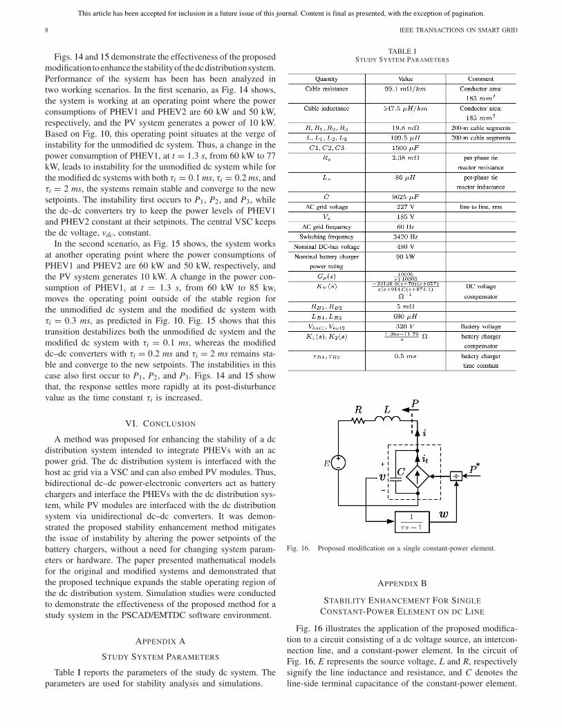
Fig. 16. Proposed modification on a single constant-power element.
APPENDIX B
STABILITY ENHANCEMENT FOR SINGLE
CONSTANT-POWER ELEMENT ON DC LINE
Fig. 16 illustrates the application of the proposed modifica-tion to a circuit consisting of a dc voltage source, an intercon-nection line, and a constant-power element. In the circuit ofFig. 16, E represents the source voltage, L and R, respectivelysignify the line inductance and resistance, and C denotes theline-side terminal capacitance of the constant-power element.
This article has been accepted for inclusion in a future issue of this journal. Content is final as presented, with the exception of pagination.
TABARI AND YAZDANI: STABILITY OF A DC DISTRIBUTION SYSTEM FOR POWER SYSTEM INTEGRATION OF PHEVs 9
The dynamics of the circuit of Fig. 16 are governed by thefollowing differential equations:
Ldi
dt= −Ri + v − E (24)
τdw
dt= v − w (25)
Cdv
dt= i − P∗
w. (26)
It can be shown that the existence condition for steady-stateoperating point of the system is
P∗ ≥ −E2
4R. (27)
It also can be shown that the steady-state voltage of theconstant-power element, V , is always greater than half of dcvoltage source, E, for all operating points
V ≥ E
2. (28)
The linearized form of (25) is
Cdv
dt= i + P∗
V2w. (29)
The eigenvalues of the linearized system can be found bysolving the following characteristic equation:
LCτλ3 + RCτλ2 +(
P∗
V2L + RC + τ
)λ + P∗
V2R + 1 = 0.
(30)
Based on Routh–Horwiz stability test, the system is stableif and only if
P∗ > −V2
R(31)
and
P∗ > −RCV2
L− τV2
L(32)
and
R
(P∗
V2L + RC + τ
)> L
(1 + P∗
V2R
). (33)
Considering (27) and (28), inequality (31) is always truefor all operating points of the system. It can be shown that bychoosing τ as
τ >L
R− RC (34)
the inequalities (32) and (33) always hold, and therefore, thesystem is always stable in its operating point range. This meansthat by choosing a proper value for τ , based on parameters ofthe dc line, the proposed modification stabilizes the dc systemwith the constant-power element.
As inequality (34) indicates, a dc system with largernetwork-side dc–dc converter capacitances and/or smallerinterconnection cable L/R ratios requires smaller values forthe time constant τi to ensure stability. In the other words,
larger network-side capacitances and smaller cable L/R ratioshave stabilizing effects on the dc system.
REFERENCES
[1] D. P. Tuttle and R. Baldick, “The evolution of plug-in electric vehicle-grid interactions,” IEEE Trans. Smart Grid, vol. 3, no. 1, pp. 500–505,Mar. 2012.
[2] K. Clement-Nyns, E. Haesen, and J. Driesen, “The impact of chargingplug-in hybrid electric vehicles on a residential distribution grid,” IEEETrans. Power Syst., vol. 25, no. 1, pp. 371–380, Feb. 2010.
[3] K. Sikes et al., “Plug-in hybrid electric vehicle market intro-duction study,” U.S. Dept. Energy, Washington, DC, USA,Final Rep. ORNL/TM-2010/46, Jul. 2010.
[4] W. Su and M. Chow, “Performance evaluation of an EDA-based large-scale plug-in hybrid electric vehicle charging algorithm,” IEEE Trans.Smart Grid, vol. 3, no. 1, pp. 308–315, Mar. 2012.
[5] S. Han, S. Han, and K. Sezaki, “Development of an optimal vehicle-to-grid aggregator for frequency regulation,” IEEE Trans. Smart Grid,vol. 1, no. 1, pp. 65–72, Jun. 2010.
[6] M. Kisacikoglu, B. Ozpineci, and L. M. Tolbert, “Examination of aPHEV bidirectional charger system for V2G reactive power compen-sation,” in Proc. 25th Annu. IEEE Appl. Power Electron. Conf. Expo.(APEC), Palm Springs, CA, USA, Feb. 2010, pp. 458–465.
[7] Y. Gurkaynak and A. Khaligh, “Control and power management of a gridconnected residential photovoltaic system with plug-in hybrid electricvehicle (PHEV) load,” in Proc. 24th Annu. IEEE Appl. Power Electron.Conf. Expo. (APEC), Washington, DC, USA, Feb. 2009, pp. 2086–2091.
[8] M. Yilmaz and P. T. Krein, “Review of battery charger topologies,charging power levels, and infrastructure for plug-in electric and hybridvehicles,” IEEE Trans. Power Electron., vol. 28, no. 5, pp. 2151–2169,May 2013.
[9] A. Khaligh and S. Dusmez, “Comprehensive topological analysis of con-ductive and inductive charging solutions for plug-in electric vehicles,”IEEE Trans. Veh. Technol., vol. 61, no. 8, pp. 3475–3489, Oct. 2012.
[10] Y. Du, X. Zhou, S. Bai, S. Lukic, and A. Huang, “Review of non-isolatedbi-directional dc–dc converters for plug-in hybrid electric vehicle chargestation application at municipal parking decks,” in Proc. 25th Annu.IEEE Appl. Power Electron. Conf. Expo. (APEC), Palm Springs, CA,USA, Feb. 2010, pp. 1145–1151.
[11] S. Bai, Y. Du, and S. Lukic, “Optimum design of an EV/PHEV chargingstation with dc bus and storage system,” in Proc. Energy Convers. Congr.Expo. (ECCE), Atlanta, GA, USA, Sep. 2010, pp. 1178–1184.
[12] S. Bai and S. Lukic, “Unified active filter and energy storage system foran MW electric vehicle charging station,” IEEE Trans. Power Electron.,vol. 28, no. 12, pp. 5793–5803, Dec. 2013.
[13] M. Tabari and A. Yazdani, “A dc distribution system for power systemintegration of plug-in hybrid electric vehicles,” in Proc. IEEE PowerEnergy Soc. Gen. Meet. (PES), Vancouver, BC, Canada, Jul. 2013,pp. 1–5.
[14] Y. Du, S. Lukic, B. Jacobson, and A. Huang, “Review of highpower isolated bi-directional dc–dc converters for PHEV/EV dc charg-ing infrastructure,” in Proc. Energy Convers. Congr. Expo. (ECCE),Phoenix, AZ, USA, Sep. 2011, pp. 553–560.
[15] A. Emadi, A. Khaligh, C. H. Rivetta, and G. A. Williamson, “Constantpower loads and negative impedance instability in automotive systems:Definition, modeling, stability, and control of power electronic con-verters and motor drives,” IEEE Trans. Veh. Technol., vol. 55, no. 4,pp. 1112–1125, Jul. 2006.
[16] D. Marx, P. Magne, B. Nahid-Mobarakeh, S. Pierfederici, and B. Davat,“Large signal stability analysis tools in dc power systems with constantpower loads and variable power loads—A review,” IEEE Trans. PowerElectron., vol. 27, no. 4, pp. 1773–1787, Apr. 2012.
[17] S. D. Sudhoff, K. A. Corzine, S. F. Glover, H. J. Hegner, andH. N. Robey, “DC link stabilized field oriented control of electric propul-sion systems,” IEEE Trans. Energy Convers., vol. 13, no. 1, pp. 27–33,Mar. 1998.
[18] A. M. Rahimi and A. Emadi, “Active damping in DC/DC power elec-tronic converters: A novel method to overcome the problems of constantpower loads,” IEEE Trans. Ind. Electron., vol. 56, no. 5, pp. 1428–1439,May 2009.
[19] A. Emadi and M. Ehsani, “Negative impedance stabilizing controlsfor PWM dc–dc converters using feedback linearization techniques,”in Proc. 35th Intersoc. Energy Convers. Eng. Conf. Exhibit (IECEC),vol. 1. Las Vegas, NV, USA, Jul. 2000, pp. 613–620.
This article has been accepted for inclusion in a future issue of this journal. Content is final as presented, with the exception of pagination.
10 IEEE TRANSACTIONS ON SMART GRID
[20] P. Kulshrestha, L. Wang, M. Y. Chow, and S. Lukic, “Intelligent energymanagement system simulator for PHEVs at municipal parking deck ina smart grid environment,” in Proc. IEEE Power Energy Soc. Gen. Meet.(PES), Calgary, AB, USA, Jul. 2009, pp. 1–6.
[21] A. Yazdani and R. Iravani, Voltage-Sourced Converters in PowerSystems: Modeling, Control, and Applications. Hoboken, NJ, USA:Wiley, 2010.
[22] A. Kwasinski and C. N. Onwuchekwa, “Dynamic behavior and stabiliza-tion of dc microgrids with instantaneous constant-power loads,” IEEETrans. Power Electron., vol. 26, no. 3, pp. 822–834, Mar. 2011.
Mansour Tabari (S’11) is currently pursuing thePh.D. degree in electrical engineering from theUniversity of Western Ontario (UWO), London, ON,Canada.
He is a Research Assistant with the Departmentof Electrical and Computer Engineering, UWO. Hisresearch interests include design, dynamic modeling,and control of dc distribution systems and integrationof electric vehicles with the power system.
Amirnaser Yazdani (M’05–SM’09) received thePh.D. degree in electrical engineering from theUniversity of Toronto, Toronto, ON, Canada, in2005.
He was an Assistant Professor with the Universityof Western Ontario (UWO), London, ON. He is cur-rently an Associate Professor at Ryerson University,Toronto. His research interests include modeling andcontrol of electronic power converters, renewableelectric power systems, distributed generation andstorage, and microgrids. He is a co-author of the
book Voltage-Sourced Converters in Power Systems (IEEE-Wiley Press, 2010),and an Associate Editor of the IEEE TRANSACTIONS ON SUSTAINABLE
ENERGY.