Embed Size (px)
Citation preview

1
Standards
Chapter 2
Copyright 2003 Prentice-HallPanko’s Business Data Networks and Telecommunications, 4th edition

2
Warning: Difficult Material
The most difficult chapter in the book
Abstract and unfamiliar concepts
Concepts are highly interrelated
Will require especially diligent study
Must be mastered for you to do well in the rest of the course
3
Figure 2.1: Standards Govern Communication
MessageMessageClient PC Server
MessageMessage MessageMessage
Standards Typically Focus on Message Exchanges:
Message Format (Syntax)
Message Order (Responses follow Requests)
Message Semantics: Meaning of Each Message

4
Figure 2.2: Internet Protocol (IP) Packet
Version(4 bits)
HeaderLength(4 bits)
Diff-Serv (8 bits)
Total Length(16 bits)
Identification (16 bits)Flags
(3 bits) Fragment Offset
(13 bits)
Protocol (8 bits)1=ICMP, 6=TCP,
17=UDP
Time to Live(8 bits)
Header Checksum (16 bits)
Bit 0 Bit 31Figure Shows 32 Bits on Each Line

5
Figure 2.2: Internet Protocol (IP) Packet
Figure 2.2: Internet Protocol (IP) Packet
Source IP Address (32 bits)
Data Field (dozens, hundreds, or thousands of bits)
Destination IP Address (32 bits)
PaddingOptions (if any)

6
Horizontal Layered Message Communication
7
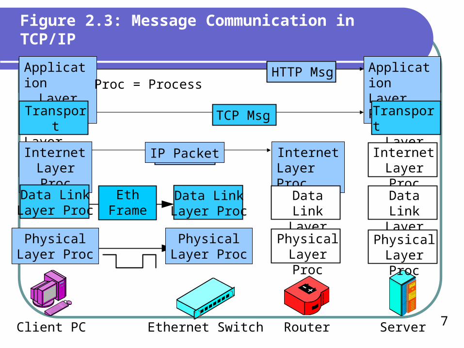
Figure 2.3: Message Communication in TCP/IP
ApplicationLayer Proc Proc = Process
HTTP Msg ApplicationLayer Proc
TransportLayer Proc
TCP Msg TransportLayer Proc
InternetLayer Proc
IP Packet InternetLayer Proc
InternetLayer Proc
Client PC ServerEthernet Switch Router
Data LinkLayer Proc
EthFrame
Data LinkLayer Proc
Data LinkLayer Proc
Data LinkLayer Proc
PhysicalLayer Proc
PhysicalLayer Proc
PhysicalLayer Proc
PhysicalLayer Proc

8
Figure 2.3: Message Communication in TCP/IP
ApplicationLayer Proc
Proc = ProcessHTTP Msg Application
Layer Proc
Client PC ServerEthernet Switch Router
Browser WebserverApplicationProgram

9
Figure 2.4: Layer Purposes
The Application Layer
The purpose of the application layer is to allow two application programs on different hosts to work together.
When a browser talks to a webserver application program, the standard for communication is the Hypertext Transfer Protocol (HTTP). This is why website URLs begin with HTTP://.
Other application layer services use different application layer standards

10
TransportLayer Proc
TransportLayer Proc TCP MsgTCP Msg Transport
Layer Proc
Host-to-Host CommunicationHTTP Requires TCP
At the Transport Layer
Client PC ServerEthernet Switch Router
Figure 2.3: Message Communication in TCP/IP

11
Figure 2.4: Layer Purposes
The Transport Layer
The purpose of the transport layer is to allow two host computers to talk to one another even if they have very different internal designs, such as a PC and a workstation server.
If you use HTTP at the application layer, you are required to use the Transmission Control Protocol (TCP) at the transport layer.
Other applications require different transport layer standards

12
Figure 2.6: Physical, Data Link, and Internet Layer Transmission
Network X
Network Z Network Y
Switches
Routers
Switches
RouteNetwork Y

13
Figure 2.3: Message Communication in TCP/IP
InternetLayer Proc
IP Packet InternetLayer Proc
InternetLayer Proc
Hop-by-Hop Communication Across an InternetHost-Router-Router-…Router-Host
Client PC ServerEthernet Switch Router

14
Figure 2.4: Layer Purposes
The Internet Layer
The purpose of the internet layer is to route packets from the source host to the destination host across one or more networks connected by routers.
TCP requires the use of the Internet Protocol (IP) at the internet layer.

15
Figure 2.3: Message Communication in TCP/IP
Data LinkLayer Proc
EthFrame
Data LinkLayer Proc
Data LinkLayer Proc
Data LinkLayer Proc
PhysicalLayer Proc
PhysicalLayer Proc
PhysicalLayer Proc
PhysicalLayer Proc
Hop-by-Hop Transmission Across One NetworkStation-Switch-Switch-…-Switch-Station
Propagation Across a Single Wire, Optical Fiber, or Radio Connection
Client PC ServerEthernet Switch Router
16
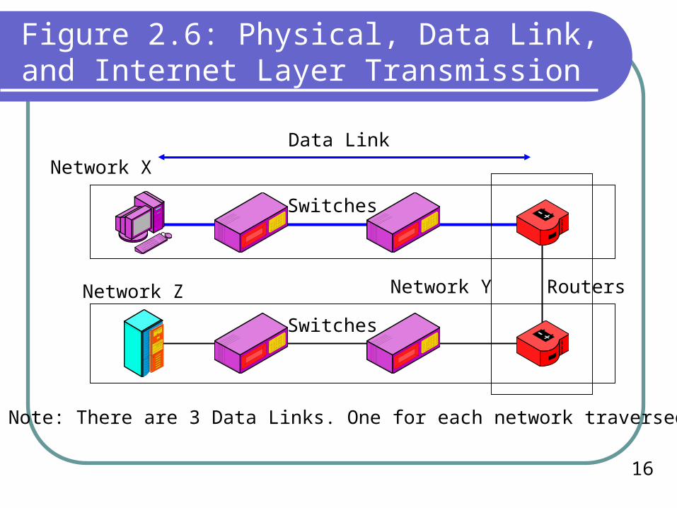
Figure 2.6: Physical, Data Link, and Internet Layer Transmission
Network X
Network Z Network Y
Switches
Routers
Switches
Data Link
Note: There are 3 Data Links. One for each network traversed

17
Figure 2.4: Layer Purposes
The Data Link Layer
The purpose of the data link layer is to govern the movement of messages from a source station to a destination station or router across a single network containing switches.
If the client station is located on an Ethernet LAN, the Ethernet data link layer standard is used (see Chapter 4) for complications to this statement).
18
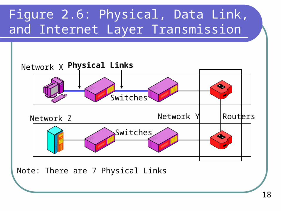
Figure 2.6: Physical, Data Link, and Internet Layer Transmission
Network X
Network Z Network Y
Switches
Routers
Switches
Physical Links
Note: There are 7 Physical Links

19
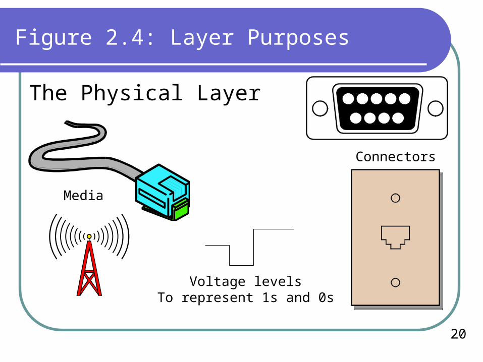
Figure 2.4: Layer Purposes
The Physical Layer
The purpose of the physical layer is to govern the transmission of bits one at a time over a wire, radio, or other connection between a station and a switch, between pairs of switches, or between a switch and a router.
For a station on an Ethernet LAN, an Ethernet physical layer standard will be used. (Ethernet offers multiple physical layer standards.)
20
Figure 2.4: Layer Purposes
The Physical Layer
Media
Connectors
Voltage levelsTo represent 1s and 0s
21
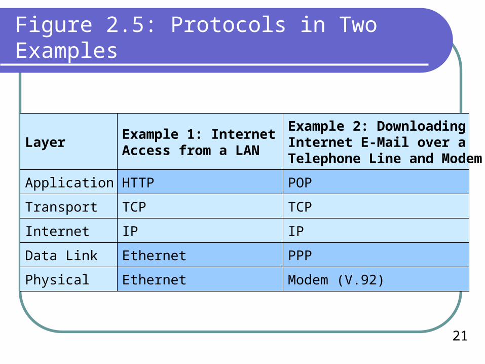
Figure 2.5: Protocols in Two Examples
HTTP POP
Physical
Layer
Data Link
Internet
Transport
Application
TCP
IP
Ethernet
Ethernet
Example 1: Internet WebAccess from a LAN
Modem (V.92)
PPP
IP
TCP
Example 2: DownloadingInternet E-Mail over a Telephone Line and Modem
22
Layers 1-3: Closer Look
Internet Layer
Data Link Layer
Physical Layer

23
Figure 2.7: Comparing the Physical, Data Link, and Internet Layers
Layer
Messagesare Called
Physical Data Link Internet
None: Bit-by-BitTransmission
Frame Packet
Switch RouterRepeaterConnectingDevice
2 31Device*Layer
*Devices are defined by their highest layer of operation. They also operate on lower layers.
24
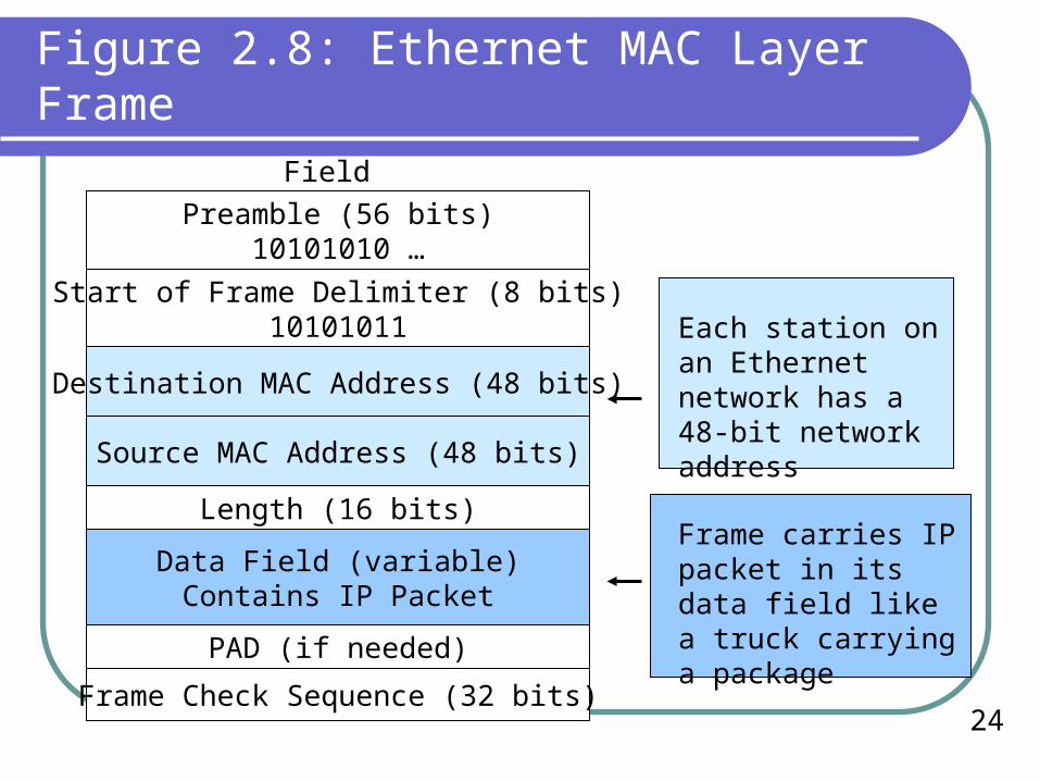
Figure 2.8: Ethernet MAC Layer Frame
Field
Preamble (56 bits)10101010 …
Start of Frame Delimiter (8 bits)10101011
Destination MAC Address (48 bits)
Source MAC Address (48 bits)
PAD (if needed)
Data Field (variable) Contains IP Packet
Length (16 bits)
Frame Check Sequence (32 bits)
Each station on an Ethernet network has a 48-bit network address
Frame carries IP packet in its data field like a truck carrying a package

25
Figure 2.7: Comparing the Physical, Data Link, and Internet Layers
Data Link InternetPhysicalLayer
Format Conversion None
Switches convertbetween differentphysical layerconnections fordifferent ports
UTP Optical Fiber
SwitchClient PC Server

26
Figure 2.7: Comparing the Physical, Data Link, and Internet Layers
Data Link InternetPhysicalLayer
Format Conversion None
Routers convertbetween differentnetworks—different physical and data link layer standards
EthernetNetwork
ATMNetwork
Router

27
Figure 2.10: All Switches in a Network and All Routers in an Internet Must Follow the Same Standard
Network 1 (Ethernet)
Network 2 (ATM)
Client PC Ethernet Switch
Ethernet Switch Ethernet Switch
Router (IP)
Router (IP)
ATM SwitchATM SwitchServer

28
Vertical Layered Communicationin a Single Host
Internet Layer
Data Link Layer
Physical Layer

29
Figure 2.11: Vertical Communication on the Source Host
IP PacketData Link Process
Host A
Internet Process
Physical Process
IP Packet
DL-T DL-HIP Packet

30
Figure 2.11: Vertical Communication on the Source Host
Internet Layer Process Creates an IP packet
Passes the packet down to the data link layer process
Data Link Layer Process Creates a new frame
Places (encapsulates) the IP packet in the data field of the frame, adding a frame header and perhaps a trailer
Passes frame down to the physical layer process
31
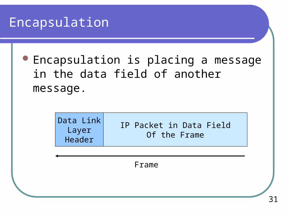
Encapsulation
Encapsulation is placing a message in the data field of another message.
Data LinkLayer
Header
IP Packet in Data FieldOf the Frame
Frame
32
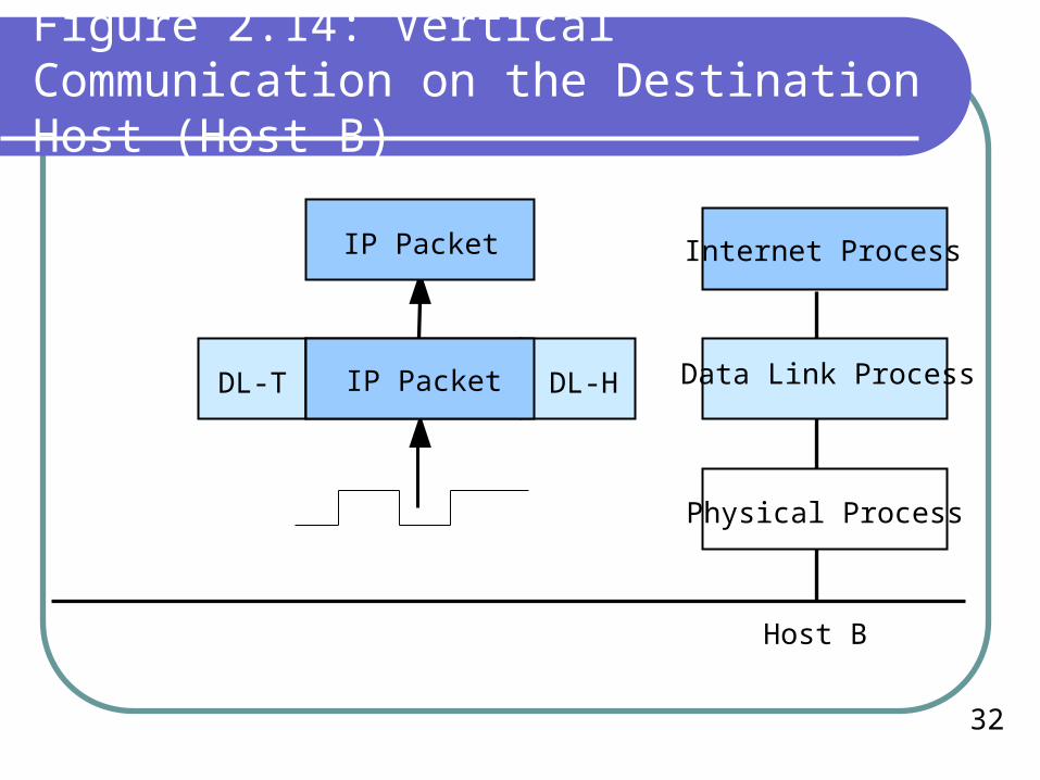
Figure 2.14: Vertical Communication on the Destination Host (Host B)
IP Packet
IP Packet
DL-T IP Packet DL-H
Internet Process
Data Link Process
Physical Process
Host B
33
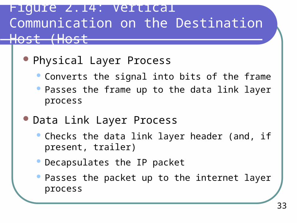
Figure 2.14: Vertical Communication on the Destination Host (Host
Physical Layer Process Converts the signal into bits of the frame Passes the frame up to the data link layer process
Data Link Layer Process Checks the data link layer header (and, if present,
trailer)
Decapsulates the IP packet
Passes the packet up to the internet layer process

34
Figure 2.12: Vertical Communication on Switch X1
Host A Switch X2
A B
Frame Frame
Switch X1
Notes:A. Switch X1 receives frame in Port 1.B. Data Link process sends frame out Port 2.
Port 1PHY
Port 2PHY
Port 3PHY
Port 4PHY
Data Link Layer Process

35
Figure 2.13: Vertical Communication on Router R1
Port 1 DL
PHY
Internet Layer Process
Port 2DL
Port 3DL
Port 4DL
PHY PHY PHY
Router R1
Switch X2
Router R1 receives frame from Switch X2 in Port 1.Port 1 DL Process decapsulates packet.Port 1 DL passes packet to internet process.
IP Packet
IP Packet
DL-T IP Packet DL-H

36
Figure 2.13: Vertical Communication on Router R1
PHY
Port 4DL
Port 1DL
PHY
Internet Layer Process
Port 2DL
Port 3DL
PHY PHY
Router R1
Router 2
Internet process sends packet out on Port 4.DL Process on Port 4 encapsulates packet in frame.DL Process passes frame to Port 4 PHY.
IP Packet
IP Packet
DL-T IP Packet DL-H

37
Figure 2.15: Transport and Application Layer Standards
Notes: Transport standard can connect computers of different types.Transport standard often is reliable (corrects errors)
Transport Layer
App 1 App 2 App 3 App 4
Client PC
Network or Internet
Server

38
Figure 2.15: Transport and Application Layer Standards
Notes: Application standard links specific pairs of applications on different multitasking hosts.
Application LayerApp 1 App 2 App 3 App 4
Client PC
Network or Internet
Server

39
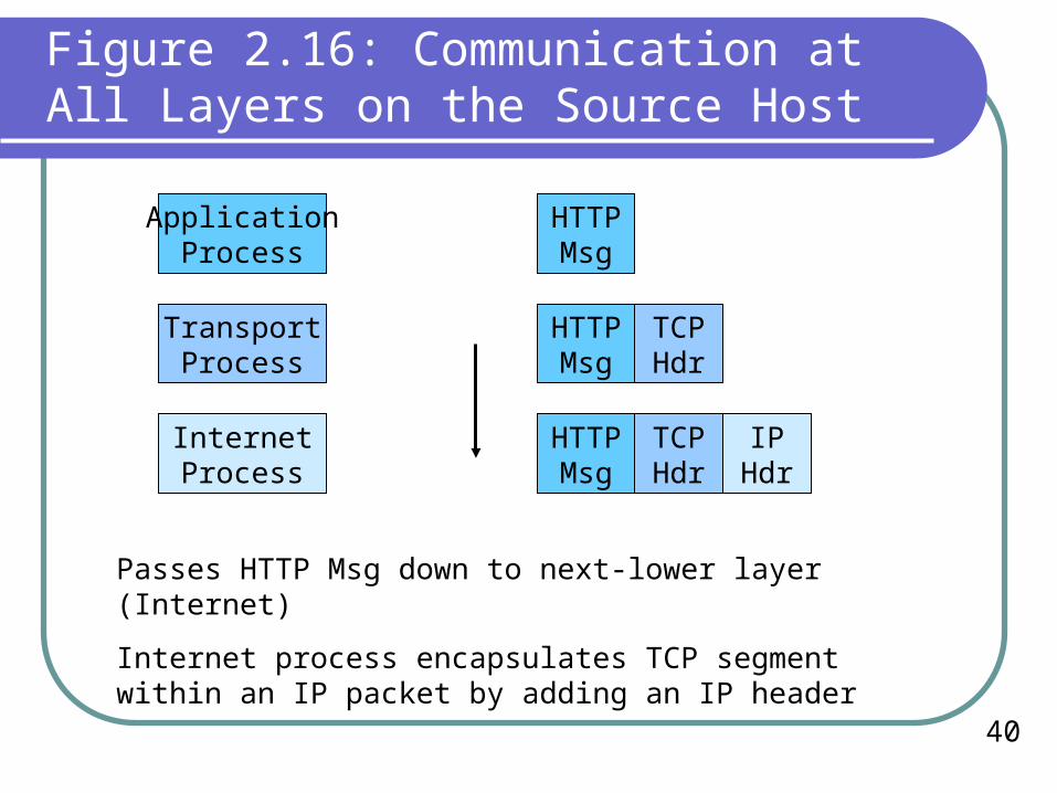
Figure 2.16: Communication at All Layers on the Source Host
HTTPMsg
ApplicationProcess
TCPHdr
HTTPMsg
TransportProcess
Application process creates an HTTP message.
Passes HTTP Msg down to next-lower layer (Transport).
Transport process encapsulates HTTP message within a TCP message (called a segment) by adding a TCP header.
TCP Message(TCP Segment)
40
Figure 2.16: Communication at All Layers on the Source Host
HTTPMsg
ApplicationProcess
TCPHdr
HTTPMsg
TransportProcess
TCPHdr
IPHdr
HTTPMsg
InternetProcess
Passes HTTP Msg down to next-lower layer (Internet)
Internet process encapsulates TCP segment within an IP packet by adding an IP header

41
Figure 2.16: Communication at All Layers on the Source Host
HTTPMsg
ApplicationProcess
TCPHdr
HTTPMsg
TransportProcess
TCPHdr
IPHdr
HTTPMsg
InternetProcess
DLTrlr
TCPHdr
IPHdr
DLHdr
HTTPMsg
Data LinkProcess

42
Figure 2.16: Communication at All Layers on the Source Host
HTTPMsg
ApplicationProcess
TCPHdr
HTTPMsg
TransportProcess
TCPHdr
IPHdr
HTTPMsg
InternetProcess
DLTrlr
TCPHdr
IPHdr
DLHdr
HTTPMsg
Data LinkProcess
PhysicalProcess
Physical layer process converts the message to signals and sends it out
43
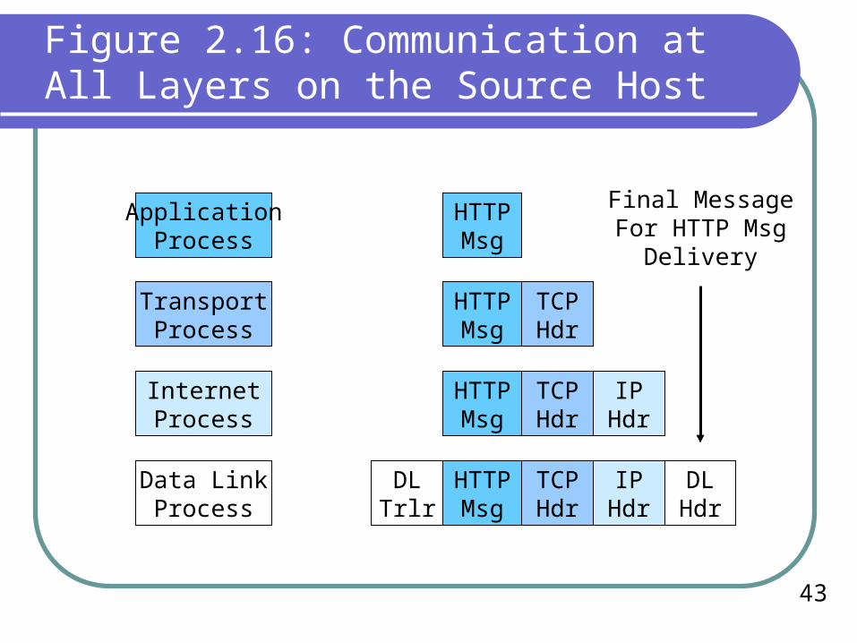
Figure 2.16: Communication at All Layers on the Source Host
HTTPMsg
ApplicationProcess
TCPHdr
HTTPMsg
TransportProcess
TCPHdr
IPHdr
HTTPMsg
InternetProcess
DLTrlr
TCPHdr
IPHdr
DLHdr
HTTPMsg
Data LinkProcess
Final MessageFor HTTP Msg
Delivery

44
Figure 2.16: Communication at All Layers on the Source Host
TCPHdr
TransportProcess
TCPHdr
IPHdr
InternetProcess
DLTrlr
TCPHdr
IPHdr
DLHdr
Data LinkProcess
Layered Communication for TCP Supervisory message Delivery
Final MessageFor TCP
SupervisoryMessage

45
Figure 2.17: TCP/IP, OSI, and TCP/IP-OSI Hybrid Architecture
Presentation
TCP/IP OSI Hybrid TCP/IP-OSI
Application Application
Application
Session
Transport
Internet
Transport
Network
Transport
Internet
Data Link
Physical
Data Link
Physical
Use OSI StandardsHere

46
Figure 2.17: TCP/IP, OSI, and TCP/IP-OSI Hybrid Architecture
The Hybrid TCP/IP-OSI Architecture is used on the Internet and dominates internal corporate networks.
The standards agencies for the OSI architecture are ISO and ITU-T.
The standards agency for TCP/IP is the IETF. TCP/IP documents are called requests for comments (RFCs).

47
Key Point
The most common standards pattern in organizations is to use OSI standards at the physical and data link layers and TCP/IP standards at the internet, transport, and application layers.
This is very important for you to keep in mind because this hybrid TCP/IP–OSI standards architecture will form the basis for most of this book.

48
Figure 2.18: OSI Session Layer (5)
Transport Layer
Client PC
Network or Internet
Server
App 1 App 2 App 3 App 4Session Layer (Layer 5)
Manages Series of TransactionsBetween Applications
Over a Transport Connection

49
Figure 2.18: OSI Session Layer (5)
OSI Very useful for applications that need to manage
exchanges of application messages closely
Few applications need this, however
TCP/IP Applications must manage application message
exchanges by themselves.
No general support in the architecture

50
Figure 2.19: OSI Presentation Layer (6)
Presentation Layer(Transfer Syntax C)App 2
Internal Syntax AApp 3
Internal Syntax B
The presentation layer governs theSyntax of messages
Hosts have different data representations, etc.Agree upon a transfer syntax for messages going between them

51
Figure 2.18: OSI Presentation Layer (6)
OSI Very useful because it handles differences in data
formatting at a general level
TCP/IP Each application must manage presentation
differences by themselves
MIME message description standards help by letting receiver know the type of file contained in a message

52
Other Standards Architectures
IPX/SPX Novell NetWare file servers
NetBEUI Small LANs with older Microsoft servers
SNA Mainframe computers
AppleTalk AppleTalk

53
Figure 2.20: Other Standards Architecture
TCP/IP IPX/SPX NetBEUI
Application NetBIOSVariousNCP*
Transport
Internet
Uses OSIStandards Here
SPX
IPX
Uses OSIStandards Here
Uses OSIStandards Here
No Internet Layer
NetBEUI

54
Figure 2.20: Other Standards Architecture
OSI SNA AppleTalk
ApplicationNo Application
Layer**Uses OSI
Layering butproprietary
protocols at eachlayer above the
physical and datalink layers
NetworkAddressableUnit (NAU)***
Services
Presentation
Session Data Flow Control
TransportTransmission
Control
Network Path Control
Uses OSIStandards Here
Uses OSIStandards Here
Data Link
Physical
TCP/IP
Application
Transport
Internet
Uses OSIStandards Here

55
Key Point
Although this book will focus on OSI at the lower layers and TCP/IP at the upper layer because of the dominance of this combination, real organizations use multiple standards architectures at higher layers (TCP/IP, IPX/SPX, SNA, AppleTalk, Net BEUI, etc).