Embed Size (px)
Citation preview

2004 Assembly & Operation ManualBlizzard® Straight Blade Snowplow
Models 760LT, 760, 800 & 860
www.blizzardplows.com
i Table of Contents
Introduction
Congratulations on purchasing the fineststraight blade snowplow available!Blizzard straight blades are clearingnew trails for innovative design, ruggeddurability, quality craftsmanship andsuperior performance. Our exclusiveproducts are manufactured and testedin Michigan’s Upper Peninsula, thesnow capital of the Midwest. With anannual snowfall averaging over 250,"we couldn’t imagine building snowremoval products anywhere else!
Your Blizzard straight blade is equippedwith versatile features designed for yearsof dependable service. The hydraulicdraw latch mounting system positivelyaligns the plow for fast installation orremoval. All Blizzard straight bladesnowplows feature an extended mold-board.This unique construction providesan additional 5" of blade that rolls snowfarther ahead and to the side whenplowing. Now you can move snowfaster, saving fuel and reducing wearon your truck and plow. Safety featuresinclude full moldboard trip action,enclosed hydraulics and automaticcylinder pressure relief.
To ensure years of optimum snowplow performance, review the contents of thismanual. It contains assembly informa-tion, detailed diagrams, complete partslistings, maintenance guidelines andtroubleshooting tips.
Should you need additional information,contact your local Blizzard snowplowdealer. Their knowledgeable staff is wellinformed on the latest straight blade information. They are also your sourcefor replacement parts, technical assis-tance and all service repairs.
Comments, suggestions or concerns?Address all correspondence to:
Blizzard CorporationCustomer Service Department95 Airpark BoulevardCalumet, MI 49913
Table of Contents01 Snowplow Accessories02 Warning!03 Snowplow Operation
Assembly Instructions04 Unpacking & Inspection05 Moldboard & A-frame Assembly09 Electrical Assembly - Plow Harness10 Electrical Assembly - Vehicle Harness12 Testing The Snowplow14 Power Hitch™ Instruction
Maintenance & Plow Specifications15 Regular Maintenance16 Storing Your Snowplow17 Plow Specifications
Plow Diagrams & Part Lists18 Models 760LT, 760, 800 & 860 Parts List22 Models 760LT, 760, 800 & 860 Assembly Schematic24 Manifold Detail with Hydraulic & Electrical Schematics
Electrical Diagrams25 Molded Plug Pin Locations26 Plow Harness27 Plow Harness Wire Schematic28 Main Lighting Harness - Triple Relay Version29 Main Lighting Harness - Triple Relay Version Wire Schematic30 Vehicle Harness31 Vehicle Harness Wire Schematic32 On/Off Switch Leads & Ground Lead
Torque Specifications33 Bolts & Hydraulic Adapters
Troubleshooting34 Troubleshooting Guide
Warranties36 Limited Consumer Warranty37 Commercial Warranty
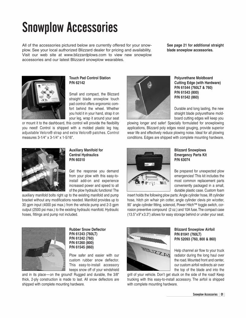
Blizzard SnowplowsEmergency Parts KitP/N 63074
Be prepared for unexpected plowemergencies! This kit includes themost common replacement partsconveniently packaged in a small,durable plastic case. Custom foam
insert holds the following plow parts: Angle cylinder hose, lift cylinderhose, hitch pin w/hair pin cotter, angle cylinder clevis pin w/cotter,90˚ angle cylinder fitting, solenoid, Power Hitch™ toggle switch, cor-rosion preventive compound (2 oz.) and 10A fuse.The compact case(13.5"x9"x3.3") allows for easy storage behind or under your seat.
Blizzard Snowplow AirfoilP/N 81041 (760LT)P/N 52093 (760, 800 & 860)
Help channel air flow to your truckradiator during the long haul overthe road. Mounted front and center,our custom airfoil redirects air overthe top of the blade and into the
grill of your vehicle. Don’t get stuck on the side of the road! Keeptrucking with this easy-to-install accessory. The airfoil is shippedwith complete mounting hardware.
Snowplow Accessories 01
Snowplow AccessoriesAll of the accessories pictured below are currently offered for your snow-plow. See your local authorized Blizzard dealer for pricing and availability.Visit our web site at www.blizzardplows.com to view new snowplowaccessories and our latest Blizzard snowplow wearables.
Touch Pad Control StationP/N 62142
Small and compact, the Blizzardstraight blade snowplow touchpad control offers ergonomic com-fort behind the wheel. Whetheryou hold it in your hand, strap it onyour leg, wrap it around your seat
or mount it to the dashboard, this control will provide the flexibilityyou need! Control is shipped with a molded plastic leg tray,adjustable Velcro® strap and extra Velcro® patches. Controlmeasures 3-1/4" x 3-1/4" x 1-5/16".
Rubber Snow DeflectorP/N 61243 (760LT)P/N 61242 (760)P/N 61260 (800)P/N 61545 (860)
Plow safer and easier with ourcustom rubber snow deflector.This easy-to-install accessorykeeps snow off of your windshield
and in its place—on the ground! Rugged and durable, the 3/8"thick, 2-ply construction is made to last. All snow deflectors areshipped with complete mounting hardware.
See page 21 for additional straightblade snowplow accessories.
Polyurethane MoldboardCutting Edge (with Hardware)P/N 61544 (760LT & 760)P/N 61543 (800)P/N 61542 (860)
Durable and long lasting, the newstraight blade polyurethane mold-board cutting edges will keep you
plowing longer and safer! Specially formulated for snowplowingapplications, Blizzard poly edges resist gouging, provide superiorwear life and effectively reduce plowing noise. Ideal for all plowingconditions. Edges are shipped with complete mounting hardware.
Auxiliary Manifold for Central HydraulicsP/N 60310
Get the response you demandfrom your plow with this easy-to-install add-on and experienceincreased power and speed to allof the plow hydraulic functions! The
auxiliary manifold bolts right up to the existing manifold and pumpbracket without any modifications needed. Manifold provides up to30 gpm input (4000 psi max.) from the vehicle pump and 2-3 gpmoutput (2500 psi max.) to the existing hydraulic manifold. Hydraulichoses, fittings and pump not included.
02 Warning!
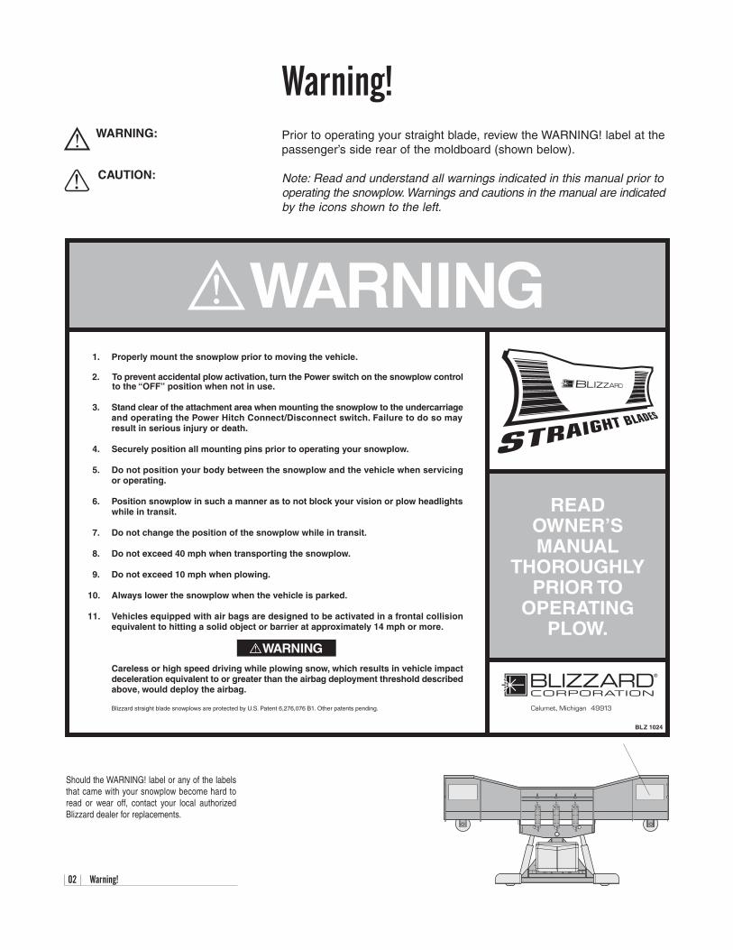
Warning!Prior to operating your straight blade, review the WARNING! label at the passenger’s side rear of the moldboard (shown below).
Note: Read and understand all warnings indicated in this manual prior tooperating the snowplow. Warnings and cautions in the manual are indicatedby the icons shown to the left.
WARNING:
CAUTION:
1. Properly mount the snowplow prior to moving the vehicle.
2. To prevent accidental plow activation, turn the Power switch on the snowplow controlto the “OFF” position when not in use.
3. Stand clear of the attachment area when mounting the snowplow to the undercarriageand operating the Power Hitch Connect/Disconnect switch. Failure to do so mayresult in serious injury or death.
4. Securely position all mounting pins prior to operating your snowplow.
5. Do not position your body between the snowplow and the vehicle when servicingor operating.
6. Position snowplow in such a manner as to not block your vision or plow headlightswhile in transit.
7. Do not change the position of the snowplow while in transit.
8. Do not exceed 40 mph when transporting the snowplow.
9. Do not exceed 10 mph when plowing.
10. Always lower the snowplow when the vehicle is parked.
11. Vehicles equipped with air bags are designed to be activated in a frontal collisionequivalent to hitting a solid object or barrier at approximately 14 mph or more.
Careless or high speed driving while plowing snow, which results in vehicle impactdeceleration equivalent to or greater than the airbag deployment threshold describedabove, would deploy the airbag.
Blizzard straight blade snowplows are protected by U.S. Patent 6,276,076 B1. Other patents pending.
READOWNER’SMANUAL
THOROUGHLYPRIOR TO
OPERATINGPLOW.
Calumet, Michigan 49913
BLZ 1024
WARNING
WARNING
Should the WARNING! label or any of the labelsthat came with your snowplow become hard toread or wear off, contact your local authorizedBlizzard dealer for replacements.
Snowplow Operation 03
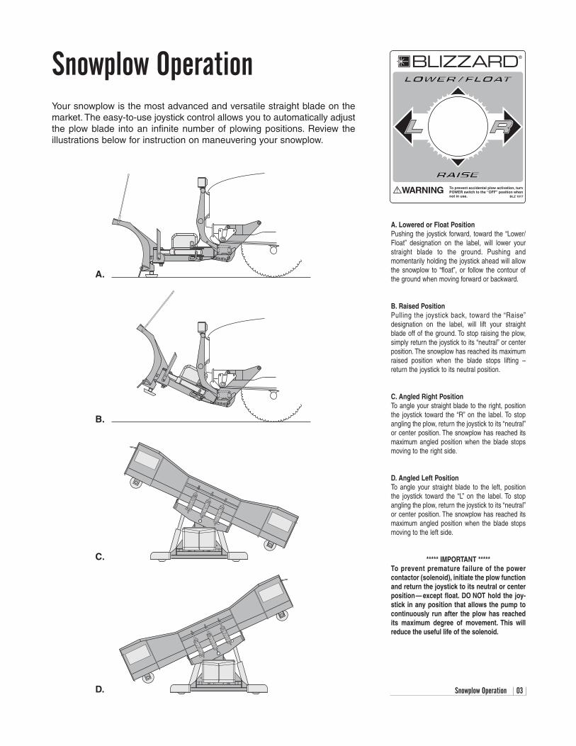
Snowplow OperationYour snowplow is the most advanced and versatile straight blade on themarket. The easy-to-use joystick control allows you to automatically adjustthe plow blade into an infinite number of plowing positions. Review theillustrations below for instruction on maneuvering your snowplow.
A.
B.
C.
D.
A. Lowered or Float PositionPushing the joystick forward, toward the “Lower/Float” designation on the label, will lower yourstraight blade to the ground. Pushing andmomentarily holding the joystick ahead will allowthe snowplow to “float”, or follow the contour ofthe ground when moving forward or backward.
B. Raised PositionPulling the joystick back, toward the “Raise”designation on the label, will lift your straightblade off of the ground. To stop raising the plow,simply return the joystick to its “neutral” or centerposition. The snowplow has reached its maximumraised position when the blade stops lifting –return the joystick to its neutral position.
C. Angled Right PositionTo angle your straight blade to the right, positionthe joystick toward the “R” on the label. To stopangling the plow, return the joystick to its “neutral”or center position. The snowplow has reached itsmaximum angled position when the blade stopsmoving to the right side.
D. Angled Left PositionTo angle your straight blade to the left, positionthe joystick toward the “L” on the label. To stopangling the plow, return the joystick to its “neutral”or center position. The snowplow has reached itsmaximum angled position when the blade stopsmoving to the left side.
***** IMPORTANT *****To prevent premature failure of the power contactor (solenoid), initiate the plow functionand return the joystick to its neutral or centerposition— except float. DO NOT hold the joy-stick in any position that allows the pump tocontinuously run after the plow has reachedits maximum degree of movement. This willreduce the useful life of the solenoid.
BLIZZARD
To prevent accidental plow activation, turnPOWER switch to the “OFF” position whennot in use. BLZ 1017
WARNING
®
04 Unpacking & Inspection
Assembly InstructionsUnpacking & Inspection
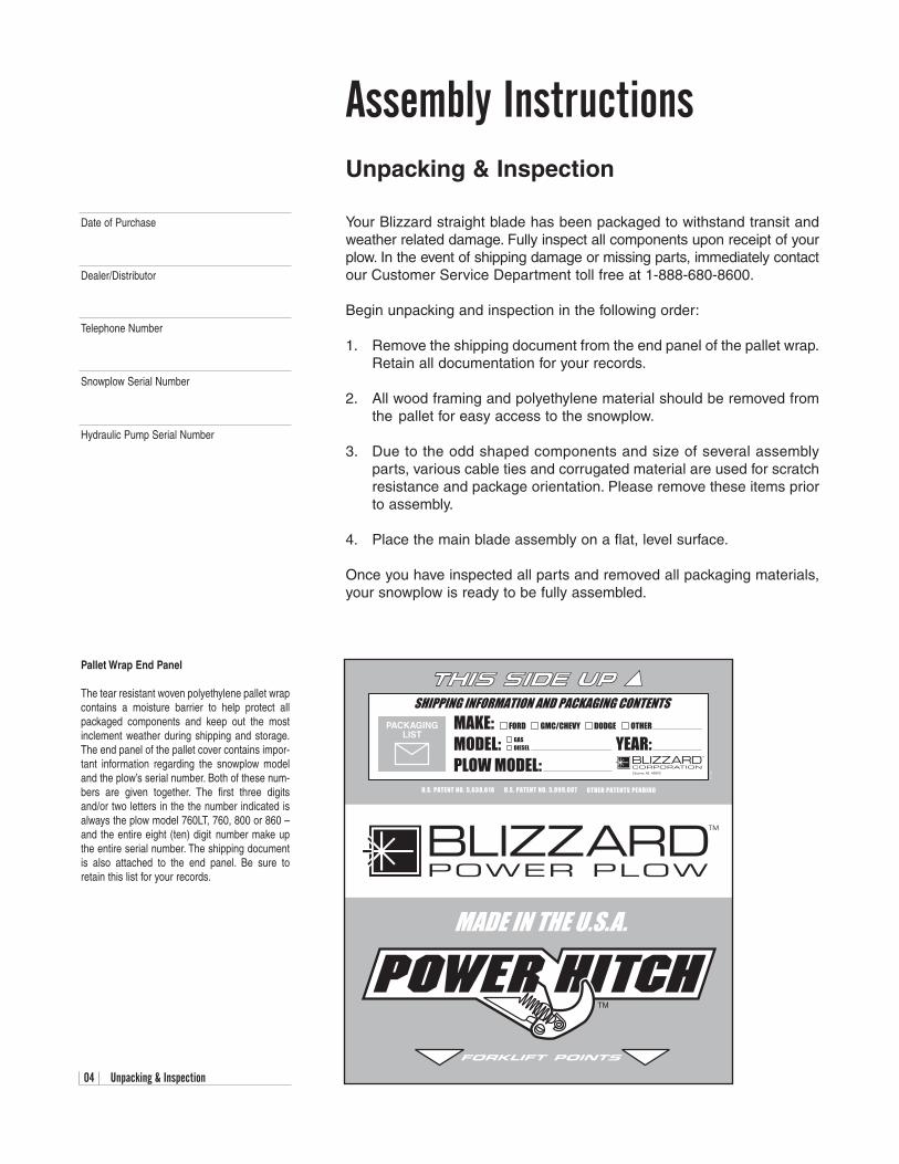
Your Blizzard straight blade has been packaged to withstand transit andweather related damage. Fully inspect all components upon receipt of yourplow. In the event of shipping damage or missing parts, immediately contactour Customer Service Department toll free at 1-888-680-8600.
Begin unpacking and inspection in the following order:
1. Remove the shipping document from the end panel of the pallet wrap.Retain all documentation for your records.
2. All wood framing and polyethylene material should be removed fromthe pallet for easy access to the snowplow.
3. Due to the odd shaped components and size of several assemblyparts, various cable ties and corrugated material are used for scratchresistance and package orientation. Please remove these items priorto assembly.
4. Place the main blade assembly on a flat, level surface.
Once you have inspected all parts and removed all packaging materials,your snowplow is ready to be fully assembled.
Pallet Wrap End Panel
The tear resistant woven polyethylene pallet wrapcontains a moisture barrier to help protect allpackaged components and keep out the mostinclement weather during shipping and storage.The end panel of the pallet cover contains impor-tant information regarding the snowplow modeland the plow’s serial number. Both of these num-bers are given together. The first three digitsand/or two letters in the the number indicated isalways the plow model 760LT, 760, 800 or 860 –and the entire eight (ten) digit number make upthe entire serial number. The shipping documentis also attached to the end panel. Be sure toretain this list for your records.
Snowplow Serial Number
Hydraulic Pump Serial Number
Telephone Number
Dealer/Distributor
Date of Purchase
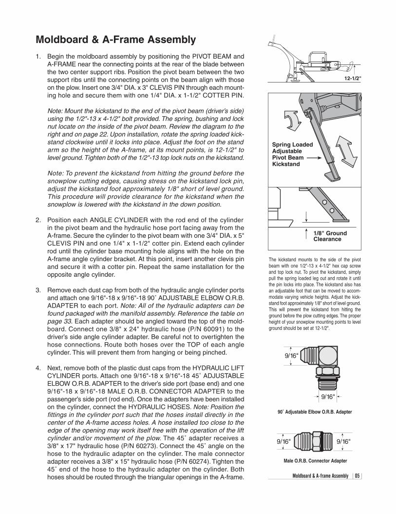
The kickstand mounts to the side of the pivotbeam with one 1/2"-13 x 4-1/2" hex cap screwand top lock nut. To pivot the kickstand, simplypull the spring loaded leg out and rotate it untilthe pin locks into place. The kickstand also hasan adjustable foot that can be moved to accom-modate varying vehicle heights. Adjust the kick-stand foot approximately 1/8" short of level ground.This will prevent the kickstand from hitting theground before the plow cutting edges. The properheight of your snowplow mounting points to levelground should be set at 12-1/2".
1/8" GroundClearance
Spring LoadedAdjustablePivot BeamKickstand
Moldboard & A-frame Assembly 05
9/16"
9/16"
90˚ Adjustable Elbow O.R.B. Adapter
Moldboard & A-Frame Assembly
1. Begin the moldboard assembly by positioning the PIVOT BEAM andA-FRAME near the connecting points at the rear of the blade betweenthe two center support ribs. Position the pivot beam between the twosupport ribs until the connecting points on the beam align with thoseon the plow. Insert one 3/4" DIA. x 3" CLEVIS PIN through each mount-ing hole and secure them with one 1/4" DIA. x 1-1/2" COTTER PIN.
Note: Mount the kickstand to the end of the pivot beam (driver’s side)using the 1/2"-13 x 4-1/2" bolt provided. The spring, bushing and locknut locate on the inside of the pivot beam. Review the diagram to theright and on page 22. Upon installation, rotate the spring loaded kick-stand clockwise until it locks into place. Adjust the foot on the standarm so the height of the A-frame, at its mount points, is 12-1/2" tolevel ground.Tighten both of the 1/2"-13 top lock nuts on the kickstand.
Note: To prevent the kickstand from hitting the ground before thesnowplow cutting edges, causing stress on the kickstand lock pin,adjust the kickstand foot approximately 1/8" short of level ground.This procedure will provide clearance for the kickstand when thesnowplow is lowered with the kickstand in the down position.
2. Position each ANGLE CYLINDER with the rod end of the cylinder in the pivot beam and the hydraulic hose port facing away from the A-frame. Secure the cylinder to the pivot beam with one 3/4" DIA. x 5"CLEVIS PIN and one 1/4" x 1-1/2" cotter pin. Extend each cylinderrod until the cylinder base mounting hole aligns with the hole on theA-frame angle cylinder bracket. At this point, insert another clevis pinand secure it with a cotter pin. Repeat the same installation for theopposite angle cylinder.
3. Remove each dust cap from both of the hydraulic angle cylinder portsand attach one 9/16"-18 x 9/16"-18 90˚ ADJUSTABLE ELBOW O.R.B.ADAPTER to each port. Note: All of the hydraulic adapters can befound packaged with the manifold assembly. Reference the table onpage 33. Each adapter should be angled toward the top of the mold-board. Connect one 3/8" x 24" hydraulic hose (P/N 60091) to the driver’s side angle cylinder adapter. Be careful not to overtighten thehose connections. Route both hoses over the TOP of each anglecylinder. This will prevent them from hanging or being pinched.
4. Next, remove both of the plastic dust caps from the HYDRAULIC LIFTCYLINDER ports. Attach one 9/16"-18 x 9/16"-18 45˚ ADJUSTABLEELBOW O.R.B. ADAPTER to the driver’s side port (base end) and one9/16"-18 x 9/16"-18 MALE O.R.B. CONNECTOR ADAPTER to thepassenger’s side port (rod end). Once the adapters have been installedon the cylinder, connect the HYDRAULIC HOSES. Note: Position thefittings in the cylinder port such that the hoses install directly in thecenter of the A-frame access holes. A hose installed too close to theedge of the opening may work itself free with the operation of the liftcylinder and/or movement of the plow. The 45˚ adapter receives a3/8" x 17" hydraulic hose (P/N 60273). Connect the 45˚ angle on thehose to the hydraulic adapter on the cylinder. The male connectoradapter receives a 3/8" x 15" hydraulic hose (P/N 60274). Tighten the45˚ end of the hose to the hydraulic adapter on the cylinder. Bothhoses should be routed through the triangular openings in the A-frame.
12-1/2"
9/16" 9/16"
Male O.R.B. Connector Adapter
06 Moldboard & A-frame Assembly (Continued)
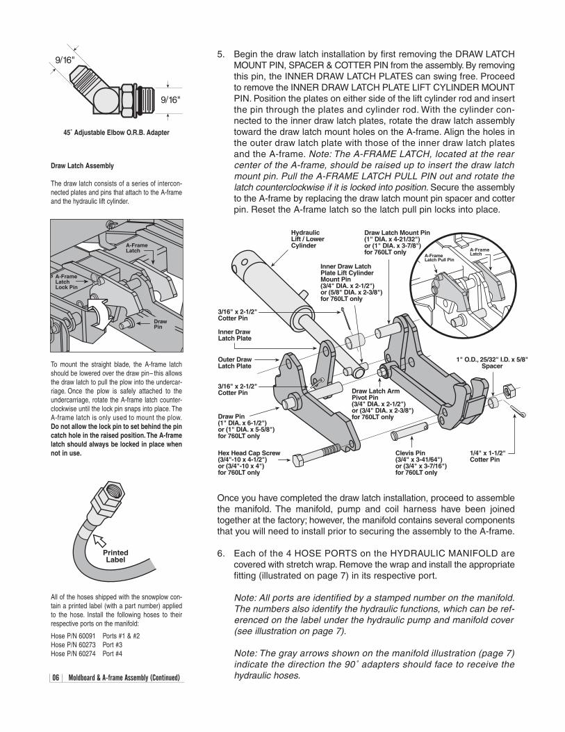
5. Begin the draw latch installation by first removing the DRAW LATCHMOUNT PIN, SPACER & COTTER PIN from the assembly. By removingthis pin, the INNER DRAW LATCH PLATES can swing free. Proceedto remove the INNER DRAW LATCH PLATE LIFT CYLINDER MOUNTPIN. Position the plates on either side of the lift cylinder rod and insertthe pin through the plates and cylinder rod. With the cylinder con-nected to the inner draw latch plates, rotate the draw latch assemblytoward the draw latch mount holes on the A-frame. Align the holes inthe outer draw latch plate with those of the inner draw latch platesand the A-frame. Note: The A-FRAME LATCH, located at the rearcenter of the A-frame, should be raised up to insert the draw latchmount pin. Pull the A-FRAME LATCH PULL PIN out and rotate thelatch counterclockwise if it is locked into position. Secure the assemblyto the A-frame by replacing the draw latch mount pin spacer and cotterpin. Reset the A-frame latch so the latch pull pin locks into place.
Once you have completed the draw latch installation, proceed to assemblethe manifold. The manifold, pump and coil harness have been joinedtogether at the factory; however, the manifold contains several componentsthat you will need to install prior to securing the assembly to the A-frame.
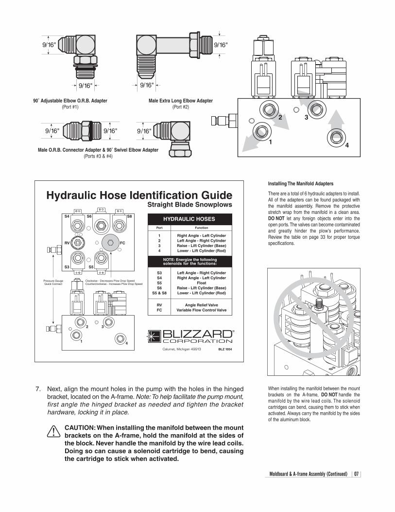
6. Each of the 4 HOSE PORTS on the HYDRAULIC MANIFOLD arecovered with stretch wrap. Remove the wrap and install the appropriatefitting (illustrated on page 7) in its respective port.
Note: All ports are identified by a stamped number on the manifold.The numbers also identify the hydraulic functions, which can be ref-erenced on the label under the hydraulic pump and manifold cover(see illustration on page 7).
Note: The gray arrows shown on the manifold illustration (page 7)indicate the direction the 90˚ adapters should face to receive thehydraulic hoses.
A-FrameLatch Pull Pin
A-FrameLatch
Outer DrawLatch Plate
Inner DrawLatch Plate
Draw Latch Mount Pin(1" DIA. x 4-21/32")or (1" DIA. x 3-7/8")for 760LT only
Inner Draw LatchPlate Lift CylinderMount Pin(3/4" DIA. x 2-1/2")or (5/8" DIA. x 2-3/8")for 760LT only
Draw Latch ArmPivot Pin(3/4" DIA. x 2-1/2")or (3/4" DIA. x 2-3/8")for 760LT only
HydraulicLift / LowerCylinder
Draw Pin(1" DIA. x 6-1/2")or (1" DIA. x 5-5/8")for 760LT only
3/16" x 2-1/2"Cotter Pin
Hex Head Cap Screw(3/4"-10 x 4-1/2")or (3/4"-10 x 4")for 760LT only
1" O.D., 25/32" I.D. x 5/8"Spacer
Clevis Pin(3/4" x 3-41/64")or (3/4" x 3-7/16")for 760LT only
1/4" x 1-1/2"Cotter Pin
3/16" x 2-1/2"Cotter Pin
Draw Latch Assembly
The draw latch consists of a series of intercon-nected plates and pins that attach to the A-frameand the hydraulic lift cylinder.
DrawPin
A-FrameLatchLock Pin
A-FrameLatch
To mount the straight blade, the A-frame latchshould be lowered over the draw pin– this allowsthe draw latch to pull the plow into the undercar-riage. Once the plow is safely attached to theundercarriage, rotate the A-frame latch counter-clockwise until the lock pin snaps into place. TheA-frame latch is only used to mount the plow.Do not allow the lock pin to set behind the pincatch hole in the raised position. The A-framelatch should always be locked in place whennot in use.
9/16"
9/16"
45˚ Adjustable Elbow O.R.B. Adapter
PrintedLabel
All of the hoses shipped with the snowplow con-tain a printed label (with a part number) appliedto the hose. Install the following hoses to theirrespective ports on the manifold:
Hose P/N 60091 Ports #1 & #2Hose P/N 60273 Port #3Hose P/N 60274 Port #4
Moldboard & A-frame Assembly (Continued) 07
9/16" 9/16" 9/16"
9/16"
9/16" 9/16"
9/16"
1
2 3
4Male O.R.B. Connector Adapter & 90˚ Swivel Elbow Adapter
(Ports #3 & #4)
90˚ Adjustable Elbow O.R.B. Adapter(Port #1)
Male Extra Long Elbow Adapter(Port #2)
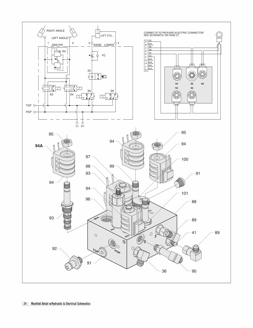
S6 S8S4
RV FC
S3 S5
Hydraulic Hose Identification GuideStraight Blade Snowplows
Calumet, Michigan 49913
HYDRAULIC HOSES
1
2 3
Port Function
S3S4S5S6
S5 & S8
BLZ 1054
NOTE: Energize the followingsolenoids for the functions:
1234
Pressure GaugeQuick Connect
Clockwise - Decreases Plow Drop SpeedCounterclockwise - Increases Plow Drop Speed
4
Right Angle - Left CylinderLeft Angle - Right CylinderRaise - Lift Cylinder (Base)Lower - Lift Cylinder (Rod)
Angle Relief ValveVariable Flow Control Valve
RVFC
Left Angle - Right CylinderRight Angle - Left Cylinder
FloatRaise - Lift Cylinder (Base)Lower - Lift Cylinder (Rod)
7. Next, align the mount holes in the pump with the holes in the hingedbracket, located on the A-frame. Note:To help facilitate the pump mount,first angle the hinged bracket as needed and tighten the brackethardware, locking it in place.
CAUTION:When installing the manifold between the mountbrackets on the A-frame, hold the manifold at the sides ofthe block. Never handle the manifold by the wire lead coils.Doing so can cause a solenoid cartridge to bend, causingthe cartridge to stick when activated.
When installing the manifold between the mountbrackets on the A-frame, DO NOT handle themanifold by the wire lead coils. The solenoid cartridges can bend, causing them to stick whenactivated. Always carry the manifold by the sidesof the aluminum block.
Installing The Manifold Adapters
There are a total of 6 hydraulic adapters to install.All of the adapters can be found packaged withthe manifold assembly. Remove the protectivestretch wrap from the manifold in a clean area.DO NOT let any foreign objects enter into theopen ports. The valves can become contaminatedand greatly hinder the plow’s performance.Review the table on page 33 for proper torquespecifications.
08 Moldboard & A-frame Assembly (Continued)
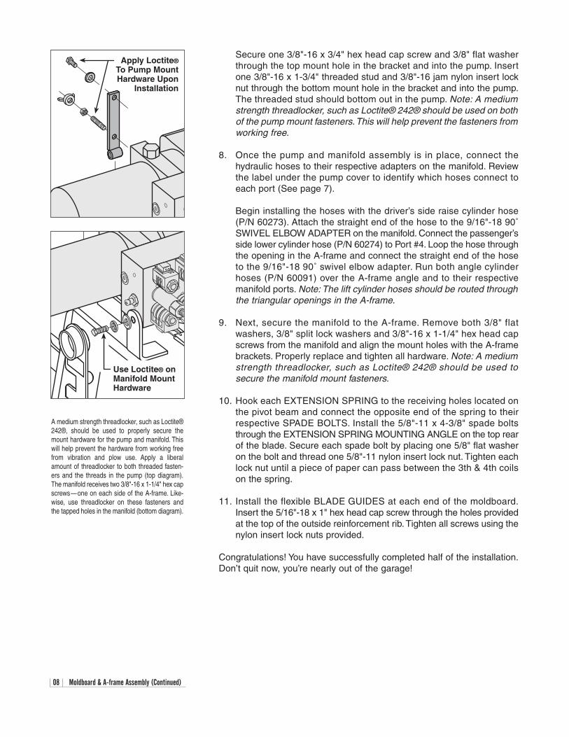
Secure one 3/8"-16 x 3/4" hex head cap screw and 3/8" flat washerthrough the top mount hole in the bracket and into the pump. Insertone 3/8"-16 x 1-3/4" threaded stud and 3/8"-16 jam nylon insert locknut through the bottom mount hole in the bracket and into the pump.The threaded stud should bottom out in the pump. Note: A mediumstrength threadlocker, such as Loctite® 242® should be used on bothof the pump mount fasteners.This will help prevent the fasteners fromworking free.
8. Once the pump and manifold assembly is in place, connect thehydraulic hoses to their respective adapters on the manifold. Reviewthe label under the pump cover to identify which hoses connect toeach port (See page 7).
Begin installing the hoses with the driver’s side raise cylinder hose(P/N 60273). Attach the straight end of the hose to the 9/16"-18 90˚SWIVEL ELBOW ADAPTER on the manifold. Connect the passenger’sside lower cylinder hose (P/N 60274) to Port #4. Loop the hose throughthe opening in the A-frame and connect the straight end of the hoseto the 9/16"-18 90˚ swivel elbow adapter. Run both angle cylinderhoses (P/N 60091) over the A-frame angle and to their respectivemanifold ports. Note: The lift cylinder hoses should be routed throughthe triangular openings in the A-frame.
9. Next, secure the manifold to the A-frame. Remove both 3/8" flat washers, 3/8" split lock washers and 3/8"-16 x 1-1/4" hex head capscrews from the manifold and align the mount holes with the A-framebrackets. Properly replace and tighten all hardware. Note: A mediumstrength threadlocker, such as Loctite® 242® should be used tosecure the manifold mount fasteners.
10. Hook each EXTENSION SPRING to the receiving holes located onthe pivot beam and connect the opposite end of the spring to theirrespective SPADE BOLTS. Install the 5/8"-11 x 4-3/8" spade boltsthrough the EXTENSION SPRING MOUNTING ANGLE on the top rearof the blade. Secure each spade bolt by placing one 5/8" flat washeron the bolt and thread one 5/8"-11 nylon insert lock nut. Tighten eachlock nut until a piece of paper can pass between the 3th & 4th coilson the spring.
11. Install the flexible BLADE GUIDES at each end of the moldboard.Insert the 5/16"-18 x 1" hex head cap screw through the holes providedat the top of the outside reinforcement rib. Tighten all screws using thenylon insert lock nuts provided.
Congratulations! You have successfully completed half of the installation.Don’t quit now, you’re nearly out of the garage!
A medium strength threadlocker, such as Loctite®242®, should be used to properly secure themount hardware for the pump and manifold. Thiswill help prevent the hardware from working freefrom vibration and plow use. Apply a liberalamount of threadlocker to both threaded fasten-ers and the threads in the pump (top diagram).The manifold receives two 3/8"-16 x 1-1/4" hex capscrews—one on each side of the A-frame. Like-wise, use threadlocker on these fasteners andthe tapped holes in the manifold (bottom diagram).
Use Loctite® onManifold MountHardware
Apply Loctite®To Pump MountHardware Upon
Installation
Electrical Assembly - Plow Harness 09
Electrical Assembly - Plow Harness
1. Begin the electrical assembly by connecting the RED POWER WIREfrom the PLOW ELECTRICAL HARNESS to the PUMP motor terminalstud using the hardware provided on the pump.
2. Place one 3/8" INTERNAL/EXTERNAL TOOTH LOCK WASHER, theBLACK GROUND WIRE (from the harness) and the RED GROUNDWIRE on the COIL WIRE HARNESS (from the manifold) over thetapped hole on the pump and secure the ground using one 3/8"-16 x3/4" hex head cap screw.
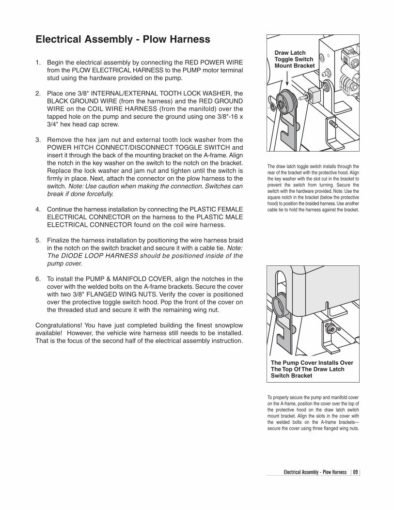
3. Remove the hex jam nut and external tooth lock washer from thePOWER HITCH CONNECT/DISCONNECT TOGGLE SWITCH andinsert it through the back of the mounting bracket on the A-frame. Alignthe notch in the key washer on the switch to the notch on the bracket.Replace the lock washer and jam nut and tighten until the switch isfirmly in place. Next, attach the connector on the plow harness to theswitch. Note: Use caution when making the connection. Switches canbreak if done forcefully.
4. Continue the harness installation by connecting the PLASTIC FEMALEELECTRICAL CONNECTOR on the harness to the PLASTIC MALEELECTRICAL CONNECTOR found on the coil wire harness.
5. Finalize the harness installation by positioning the wire harness braidin the notch on the switch bracket and secure it with a cable tie. Note:The DIODE LOOP HARNESS should be positioned inside of the pump cover.
6. To install the PUMP & MANIFOLD COVER, align the notches in thecover with the welded bolts on the A-frame brackets. Secure the coverwith two 3/8" FLANGED WING NUTS. Verify the cover is positionedover the protective toggle switch hood. Pop the front of the cover onthe threaded stud and secure it with the remaining wing nut.
Congratulations! You have just completed building the finest snowplowavailable! However, the vehicle wire harness still needs to be installed.That is the focus of the second half of the electrical assembly instruction.
Diode PackMount Bracket
Draw LatchToggle SwitchMount Bracket
The draw latch toggle switch installs through therear of the bracket with the protective hood. Alignthe key washer with the slot cut in the bracket toprevent the switch from turning. Secure theswitch with the hardware provided. Note: Use the square notch in the bracket (below the protectivehood) to position the braided harness. Use anothercable tie to hold the harness against the bracket.
The Pump Cover Installs OverThe Top Of The Draw LatchSwitch Bracket
To properly secure the pump and manifold coveron the A-frame, position the cover over the top ofthe protective hood on the draw latch switchmount bracket. Align the slots in the cover withthe welded bolts on the A-frame brackets—secure the cover using three flanged wing nuts.

10 Electrical Assembly - Vehicle Harness
Electrical Assembly - Vehicle Harness
CAUTION: Always perform the vehicle wire harness assem-bly with the vehicle off and the keys out of the ignition. Use caution when testing the electrical wires for the vehicle’sheadlight functions.
1. Begin the installation of the electrical harness under the hood. Insertthe WHITE POWER CONNECTOR & RED POWER WIRE (with FUSE)end of the harness through the driver’s side fire wall access panel intothe vehicle cab. Note:You may need to widen an opening or cut accessto the cab interior to facilitate the assembly. Loosely position theremaining portion of the harness over the driver’s side fender well andplace the MOLDED RUBBER POWER CONNECTOR near the bumper.Note: Keep the plow and vehicle rubber power connector pins lubri-cated with a liberal amount of dielectric grease. Always replace theprotective RUBBER WEATHER CAPS when the plow is disconnectedfrom the vehicle.
2. Next, attach the POWER CONTACTOR (SOLENOID) to the driver’sside wheel well or engine fan guard using two 12-14 x 3/4" hex washerself-drilling screws. Note: Some model vehicles provide mountinglocations for accessory components. Always mount the solenoid withthe terminals facing up.This will extend the useful life of the solenoid.Connect the 24" BLACK GROUND WIRE to either small terminal onthe solenoid and attach the opposite end to the vehicle with one hexwasher self-drilling screw. Locate the BROWN/WHITE PUMP SOLE-NOID ACTIVATION WIRE on the wire harness and position the eyeletover the remaining small terminal on the contactor. Secure it with thehardware provided on the solenoid.
3. Proceed to connect the BLACK VEHICLE WIRE HARNESS GROUNDWIRE to the negative terminal on the vehicle’s battery. Cut the wire tolength and crimp a 3/8" DIA. END RING TERMINAL on the wire. It isalso recommended that the ring terminal be soldered. Note: The har-ness should be secured to the vehicle prior to taking the necessarymeasurement. Measure the distance needed for the RED POWER WIRE to reach the solenoid and properly secure an end ring terminalto it. Connect the power wire to either large terminal on the solenoid.
CAUTION: Do not fasten the wire harness to areas that comein contact with moving engine parts or possess extremeheat.The harness could become tangled and/or melt causingelectrical failure and vehicle damage.
4. Attach and solder an end ring terminal to both ends of the remaininglength of the red 4 gauge wire. Connect one end of the wire to theopen terminal on the solenoid and the remaining end to the positive terminal on the battery.
5. With the vehicle harness secured to the truck, position the MAINLIGHTING HARNESS such that both of the large, gray VEHICLEHEADLIGHT CONNECTORS are near the truck headlights and thesmaller, black PLOW HEADLIGHT CONNECTORS are near the grillof the vehicle.
Power Contactor (Solenoid) - Models 760, 800& 860
There are four wires that need to be attached tothe power contactor:(A) Red Power Battery Wire(B) Vehicle Wire Harness Red Power Wire(C) 24" Black Ground Wire(D) Brown/White Pump Solenoid Activation Wire
AB
C
D
A B
C D
Power Contactor (Solenoid) - Model 760LT
Elec. Assem. - Vehicle Harness (Continued) 11
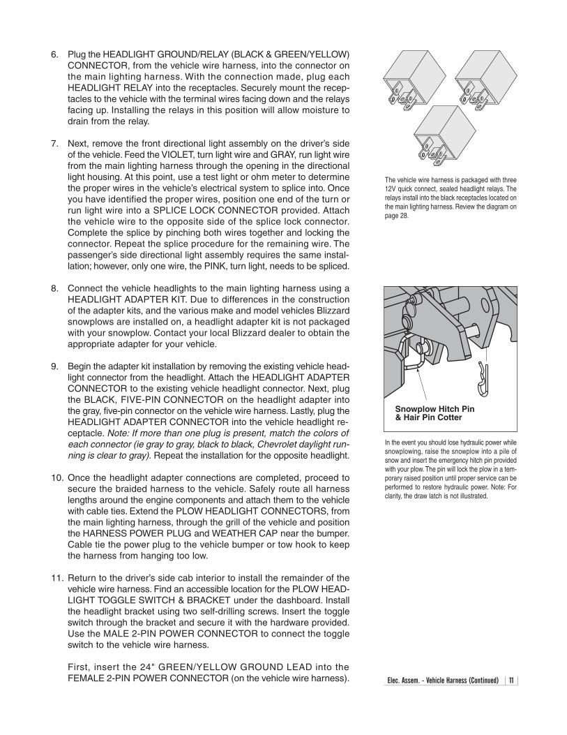
6. Plug the HEADLIGHT GROUND/RELAY (BLACK & GREEN/YELLOW)CONNECTOR, from the vehicle wire harness, into the connector onthe main lighting harness. With the connection made, plug eachHEADLIGHT RELAY into the receptacles. Securely mount the recep-tacles to the vehicle with the terminal wires facing down and the relaysfacing up. Installing the relays in this position will allow moisture todrain from the relay.
7. Next, remove the front directional light assembly on the driver’s sideof the vehicle. Feed the VIOLET, turn light wire and GRAY, run light wirefrom the main lighting harness through the opening in the directionallight housing. At this point, use a test light or ohm meter to determinethe proper wires in the vehicle’s electrical system to splice into. Onceyou have identified the proper wires, position one end of the turn orrun light wire into a SPLICE LOCK CONNECTOR provided. Attachthe vehicle wire to the opposite side of the splice lock connector.Complete the splice by pinching both wires together and locking theconnector. Repeat the splice procedure for the remaining wire. Thepassenger’s side directional light assembly requires the same instal-lation; however, only one wire, the PINK, turn light, needs to be spliced.
8. Connect the vehicle headlights to the main lighting harness using aHEADLIGHT ADAPTER KIT. Due to differences in the constructionof the adapter kits, and the various make and model vehicles Blizzardsnowplows are installed on, a headlight adapter kit is not packagedwith your snowplow. Contact your local Blizzard dealer to obtain theappropriate adapter for your vehicle.
9. Begin the adapter kit installation by removing the existing vehicle head-light connector from the headlight. Attach the HEADLIGHT ADAPTERCONNECTOR to the existing vehicle headlight connector. Next, plugthe BLACK, FIVE-PIN CONNECTOR on the headlight adapter intothe gray, five-pin connector on the vehicle wire harness. Lastly, plug theHEADLIGHT ADAPTER CONNECTOR into the vehicle headlight re-ceptacle. Note: If more than one plug is present, match the colors ofeach connector (ie gray to gray, black to black, Chevrolet daylight run-ning is clear to gray). Repeat the installation for the opposite headlight.
10. Once the headlight adapter connections are completed, proceed tosecure the braided harness to the vehicle. Safely route all harnesslengths around the engine components and attach them to the vehiclewith cable ties. Extend the PLOW HEADLIGHT CONNECTORS, fromthe main lighting harness, through the grill of the vehicle and positionthe HARNESS POWER PLUG and WEATHER CAP near the bumper.Cable tie the power plug to the vehicle bumper or tow hook to keepthe harness from hanging too low.
11. Return to the driver’s side cab interior to install the remainder of the vehicle wire harness. Find an accessible location for the PLOW HEAD-LIGHT TOGGLE SWITCH & BRACKET under the dashboard. Installthe headlight bracket using two self-drilling screws. Insert the toggleswitch through the bracket and secure it with the hardware provided.Use the MALE 2-PIN POWER CONNECTOR to connect the toggleswitch to the vehicle wire harness.
First, insert the 24" GREEN/YELLOW GROUND LEAD into the FEMALE 2-PIN POWER CONNECTOR (on the vehicle wire harness).
The vehicle wire harness is packaged with three12V quick connect, sealed headlight relays. Therelays install into the black receptacles located onthe main lighting harness. Review the diagram on page 28.
Snowplow Hitch Pin& Hair Pin Cotter
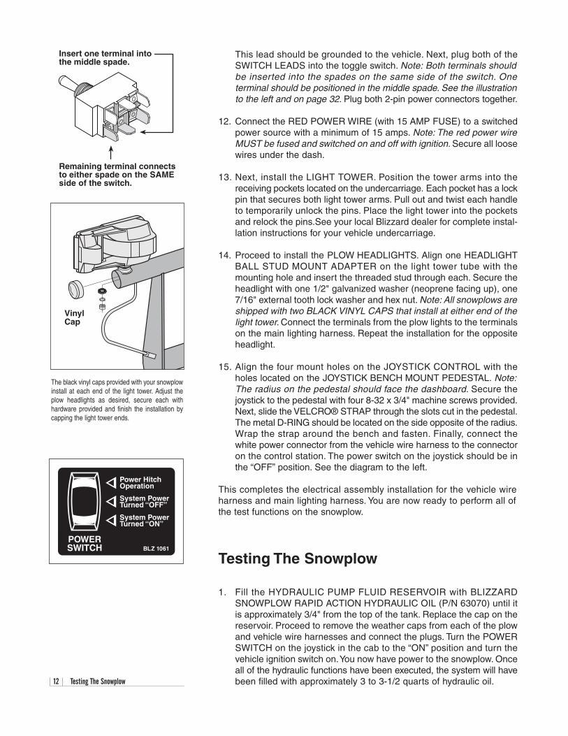
In the event you should lose hydraulic power whilesnowplowing, raise the snowplow into a pile ofsnow and insert the emergency hitch pin providedwith your plow. The pin will lock the plow in a tem-porary raised position until proper service can beperformed to restore hydraulic power. Note: Forclarity, the draw latch is not illustrated.
12 Testing The Snowplow
This lead should be grounded to the vehicle. Next, plug both of theSWITCH LEADS into the toggle switch. Note: Both terminals shouldbe inserted into the spades on the same side of the switch. One terminal should be positioned in the middle spade. See the illustrationto the left and on page 32. Plug both 2-pin power connectors together.
12. Connect the RED POWER WIRE (with 15 AMP FUSE) to a switchedpower source with a minimum of 15 amps. Note: The red power wireMUST be fused and switched on and off with ignition. Secure all loosewires under the dash.
13. Next, install the LIGHT TOWER. Position the tower arms into thereceiving pockets located on the undercarriage. Each pocket has a lockpin that secures both light tower arms. Pull out and twist each handleto temporarily unlock the pins. Place the light tower into the pocketsand relock the pins.See your local Blizzard dealer for complete instal-lation instructions for your vehicle undercarriage.
14. Proceed to install the PLOW HEADLIGHTS. Align one HEADLIGHTBALL STUD MOUNT ADAPTER on the light tower tube with themounting hole and insert the threaded stud through each. Secure theheadlight with one 1/2" galvanized washer (neoprene facing up), one7/16" external tooth lock washer and hex nut. Note: All snowplows areshipped with two BLACK VINYL CAPS that install at either end of thelight tower. Connect the terminals from the plow lights to the terminalson the main lighting harness. Repeat the installation for the oppositeheadlight.
15. Align the four mount holes on the JOYSTICK CONTROL with theholes located on the JOYSTICK BENCH MOUNT PEDESTAL. Note:The radius on the pedestal should face the dashboard. Secure thejoystick to the pedestal with four 8-32 x 3/4" machine screws provided.Next, slide the VELCRO® STRAP through the slots cut in the pedestal.The metal D-RING should be located on the side opposite of the radius.Wrap the strap around the bench and fasten. Finally, connect thewhite power connector from the vehicle wire harness to the connectoron the control station. The power switch on the joystick should be inthe “OFF” position. See the diagram to the left.
This completes the electrical assembly installation for the vehicle wireharness and main lighting harness. You are now ready to perform all ofthe test functions on the snowplow.
Testing The Snowplow
1. Fill the HYDRAULIC PUMP FLUID RESERVOIR with BLIZZARDSNOWPLOW RAPID ACTION HYDRAULIC OIL (P/N 63070) until itis approximately 3/4" from the top of the tank. Replace the cap on thereservoir. Proceed to remove the weather caps from each of the plowand vehicle wire harnesses and connect the plugs. Turn the POWERSWITCH on the joystick in the cab to the “ON” position and turn thevehicle ignition switch on.You now have power to the snowplow. Onceall of the hydraulic functions have been executed, the system will havebeen filled with approximately 3 to 3-1/2 quarts of hydraulic oil.
Insert one terminal intothe middle spade.
Remaining terminal connectsto either spade on the SAMEside of the switch.
VinylCap
The black vinyl caps provided with your snowplowinstall at each end of the light tower. Adjust theplow headlights as desired, secure each withhardware provided and finish the installation bycapping the light tower ends.
Power HitchOperation
BLZ 1061
System PowerTurned “OFF”
System PowerTurned “ON”
POWERSWITCH
Testing The Snowplow (Continued) 13
2. Raise the POWER HITCH on the snowplow by pushing and holding thetoggle switch on the A-frame upward into the “CONNECT” position.Note: The switch on the control must be in the “POWER HITCHOPERATION” position before the Power Hitch will function. See the label illustration on page 12. Notice the action of the fluid in the reservoir.By activating the initial hydraulic function, the fluid begins to fill thesystem. Push and hold the toggle switch in the “DISCONNECT” position,the draw latch will lower. Refill the reservoir until the fluid is 3/4" fromthe top of the tank.
3. Position the vehicle such that the draw latch is below the push beamand the mounting points on the A-frame are in line with the mountingpoints on the undercarriage. Pull out the A-FRAME LATCH PIN androtate the A-FRAME LATCH clockwise until the latch is resting on theDRAW PIN (See diagram on page 14). Move the snowplow in positionby activating the draw latch connect switch and release.
WARNING: Always use caution when operating the drawlatch CONNECT/DISCONNECT switch. Keep your hands andfeet away from the operation of the draw latch and the mainblade. The action of the draw latch moves the snowplow inposition for proper attachment to the vehicle. Failure to followthis warning may result in serious injury or death.
The Power Hitch will raise until it hits the push beam and the DRAWLATCH FINGERS will pull the plow into the vehicle. The mountingpoints on the plow and vehicle are now positively aligned. Rotate theA-frame latch counterclockwise until the latch is locked in the raisedposition. Note: The A-frame latch pin should always lock in place. Donot set the pin past the lock point on the A-frame. Insert the twoHITCH PINS through the mounting holes on the A-frame and secureeach with one hair pin cotter. The snowplow is now securely mountedto the vehicle.
4. Return to the interior of the vehicle. With the plow securely in place,you can now execute the remaining functions of the snowplow. Thepower supply on the joystick should be in the “ON” position. Next, raisethe plow to its maximum height by pulling back (“RAISE”) on the joy-stick. Angle the snowplow to the left by moving the joystick toward the“L” (left angle) on the label. If the plow function is slow or delayed, thehydraulic fluid is filling the cylinder and replacing the air in the system.Continue testing the remaining joystick functions. Monitor the fluid levelin the reservoir and fill to 3/4" from the top of the tank if needed. Also,look for any hydraulic fluid leaks around the manifold, pump, hydraulichoses and all cylinders.
5. Lastly, check that the vehicle and plow headlights are in proper work-ing condition including the turn signals. If necessary, adjust the plowheadlight beams with the plow in the raised position.
Congratulations on a successful assembly and installation! Once all of theblade and electrical functions have been tested your Blizzard straightblade is ready for action. Should you need additional support during aplow assembly or undercarriage installation, contact your local authorizedBlizzard dealer.
BLIZZARD
To prevent accidental plow activation, turnPOWER switch to the “OFF” position whennot in use. BLZ 1017
WARNING
®
Your Blizzard straight blade snowplow will useapproximately 1-1/2 to 2 quarts of Blizzard RapidAction Hydraulic Oil. Blizzard hydraulic oil is alsoavailable by the case (P/N 63071), gallon (P/N63072) or gallon case (P/N 63069). See yourlocal authorized Blizzard dealer for price andavailability.
14 Mounting & Dismounting Instructions
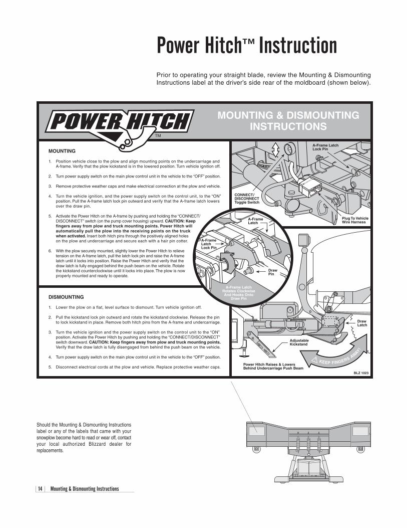
Power Hitch™InstructionPrior to operating your straight blade, review the Mounting & DismountingInstructions label at the driver’s side rear of the moldboard (shown below).
MOUNTING & DISMOUNTINGINSTRUCTIONS
Power Hitch Raises & LowersBehind Undercarriage Push Beam
MOUNTING
1. Position vehicle close to the plow and align mounting points on the undercarriage andA-frame. Verify that the plow kickstand is in the lowered position. Turn vehicle ignition off.
2. Turn power supply switch on the main plow control unit in the vehicle to the “OFF” position.
3. Remove protective weather caps and make electrical connection at the plow and vehicle.
4. Turn the vehicle ignition, and the power supply switch on the control unit, to the “ON”position. Pull the A-frame latch lock pin outward and verify that the A-frame latch lowersover the draw pin.
5. Activate the Power Hitch on the A-frame by pushing and holding the “CONNECT/ DISCONNECT” switch (on the pump cover housing) upward. CAUTION: Keepfingers away from plow and truck mounting points. Power Hitch willautomatically pull the plow into the receiving points on the truckwhen activated. Insert both hitch pins through the positively aligned holeson the plow and undercarriage and secure each with a hair pin cotter.
6. With the plow securely mounted, slightly lower the Power Hitch to relievetension on the A-frame latch, pull the latch lock pin and raise the A-frame
latch until it locks into position. Raise the Power Hitch and verify that thedraw latch is fully engaged behind the push beam on the vehicle. Rotatethe kickstand counterclockwise until it locks into place. The plow is nowproperly mounted and ready to operate.
DISMOUNTING
1. Lower the plow on a flat, level surface to dismount. Turn vehicle ignition off.
2. Pull the kickstand lock pin outward and rotate the kickstand clockwise. Release the pinto lock kickstand in place. Remove both hitch pins from the A-frame and undercarriage.
3. Turn the vehicle ignition and the power supply switch on the control unit to the “ON”position. Activate the Power Hitch by pushing and holding the “CONNECT/DISCONNECT”switch downward. CAUTION: Keep fingers away from plow and truck mounting points.Verify that the draw latch is fully disengaged from behind the push beam on the vehicle.
4. Turn power supply switch on the main plow control unit in the vehicle to the “OFF” position.
5. Disconnect electrical cords at the plow and vehicle. Replace protective weather caps.
AdjustableKickstand
DrawLatch
KEEP FINGERS AWAY!
BLZ 1023
A-Frame LatchLock Pin
Plug To VehicleWire Harness
CONNECT /DISCONNECTToggle Switch
A-Frame LatchRotates ClockwiseAnd Hooks Onto
Draw Pin
DrawPin
A-FrameLatchLock Pin
A-FrameLatch
TM
Should the Mounting & Dismounting Instructionslabel or any of the labels that came with yoursnowplow become hard to read or wear off, contactyour local authorized Blizzard dealer forreplacements.

Regular Maintenance 15
Regular MaintenanceYour Blizzard straight blade snowplow has been designed for years ofrugged, dependable service with low maintenance. To ensure properworking condition, follow the maintenance guidelines below and on thenext page.
CAUTION: Always follow the maintenance guidelines in a timelyfashion. Failure to observe maintenance guidelines may resultin poor snowplow operation, increased component wear orpossibly lead to part failure.
Routinely inspect the following items – perform maintenance as needed:
1. All fasteners, pins, nuts and bolts for tightness. See the recommendedmaximum bolt torque chart on page 33.
2. All hydraulic hoses and hydraulic hose adapters for wear and leaks.See the recommended hydraulic adapter torque values on page 33.
3. All cylinders for leaks; inspect rod ends for corrosion and pitting.
4. Cutting edges and plow shoes for wear. Do not discard plow shoewashers. These should be retained for different shoe adjustments.
5. Clean and lubricate all electrical plugs, headlight connections, groundand battery cables, solenoid connections and switch connections toprevent corrosion. Apply dielectric grease for every 25 hours of snow-plow use.You may need to grease more frequently depending on yourplowing environment.
6. Lubricate all pins and bushings to prevent corrosion and to maintainconsistent operation, including the A-frame latch. A NLGI Grade 2multipurpose lithium complex grease with molybdenum (MPGM) isrecommended for lubrication.
7. Clean and cover deep scratches or exposed metal with Blizzard Snow-plow white (P/N 61219) or black (P/N 63073) touch-up paint. Contactyour local Blizzard Dealer for availability.
8. Check the hydraulic oil level in the hydraulic pump fluid reservoir. Fillthe fluid to within 3/4" from the top of the reservoir. Do not exceed thislevel. Never mix different types of fluids. Contact your local dealer forreplacement Blizzard Snowplow Rapid Action Hydraulic Oil (P/N 63070).
9. Check the trip spring adjustment. Properly adjusted tension will allowa sheet of paper to pass between the 3rd and 4th coils of the spring.
10. To adjust the snowplow drop speed, use the variable flow control valve(FC) on the manifold (see label under pump & manifold cover). Turn thedial on the valve clockwise to decrease the drop speed. Turn the dialcounterclockwise to increase the drop speed. See the TroubleshootingGuide on page 35 for additional instructions.
11. Do not allow snow and ice to build-up on the pump and manifold cover.Excessive build-up may cause bumper damage when the plow is raised.
Maintenance ScheduleMaintenance Performed Date
16 Storing Your Snowplow
Storing Your SnowplowPlacing Your Plow In Storage
1. Position your plow on a flat, level surface for storage. Follow the dis-mounting procedure illustrated on page 14.
2. Pressure wash and dry the entire snowplow prior to placing in storage.
3. Apply a liberal amount of dielectric grease to all electrical plugs andconnections. Clean and install all dust caps.
4. Lubricate all exposed hydraulic cylinder rod ends with liquid white lithium grease to prevent corrosion.
5. Lubricate all pins and bushings to prevent corrosion and to maintainconsistent operation, including the A-frame latch. A NLGI Grade 2multipurpose lithium complex grease with molybdenum (MPGM) isrecommended for lubrication.
6. Clean and cover deep scratches or exposed metal with Blizzard Snow-plow white (P/N 61219) or black (P/N 63073) touch-up paint. Contactyour local Blizzard dealer for availability.
7. Remove and properly discard the fluid from the pump reservoir. Cleanthe pump filter and replace the hydraulic oil to within 3/4" from the topof the reservoir. Changing the fluid annually will prolong the life of yourpump and manifold. Never mix different types of hydraulic oil. Contactyour local dealer for replacement Blizzard Snowplow Rapid ActionHydraulic Oil (P/N 63070).
8. Cover the snowplow with a tarp if stored outside. This will protect yourplow from sun fading and inclement weather which can lead toaccelerated corrosion.
Removing Your Plow From Storage
1. Perform all regular maintenance indicated on page 15.
2. If you have not replaced the hydraulic oil in the pump reservoir, it isstrongly encouraged that you do so prior to operating your plow. Pro-longed storage could result in condensation build-up.
3. Follow the mounting procedure illustrated on page 14.
4. Once the plow has been properly mounted to the vehicle and all electrical connections have been made, initiate all of the functions ofthe snowplow. Monitor the fluid level in the reservoir and fill to 3/4" fromthe top of the tank if needed.
5. Adjust the snowplow headlights as needed.
Annual Fluid ReplacementType & Quantity of Fluid Replaced Date
Plow Specifications 17
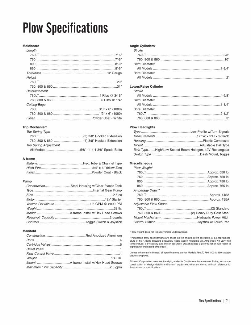
Plow SpecificationsMoldboard
Length760LT ..................................................................................7'-6"760 ......................................................................................7'-6"800 ......................................................................................8'-0"860 ......................................................................................8'-6"
Thickness ........................................................................12 GaugeHeight
760LT ....................................................................................29"760, 800 & 860 ......................................................................31"
Reinforcement760LT..................................................................4 Ribs @ 3/16"760, 800 & 860 ....................................................6 Ribs @ 1/4"
Cutting Edge760LT ................................................................3/8" x 6" (1080)760, 800 & 860 ..................................................1/2" x 6" (1080)
Finish ............................................................Powder Coat - White
Trip MechanismTrip Spring Type
760LT ................................................(3) 3/8" Hooked Extension760, 800 & 860 ................................(4) 3/8" Hooked Extension
Trip Spring AdjustmentAll Models ......................................5/8"-11 x 4-3/8" Spade Bolts
A-frameMaterial ................................................Rec. Tube & Channel TypeHitch Pins........................................................3/4" x 6" Yellow ZincFinish..............................................................Powder Coat - Black
PumpConstruction ............................Steel Housing w/Clear Plastic TankType ................................................................Internal Gear PumpSize ......................................................................................2.5 ccMotor ............................................................................12V StarterVolume Per Minute ......................................1.6 GPM @ 2000 PSIWeight ....................................................................................32 lb.Mount ....................................A-frame Install w/Hex Head ScrewsReservoir Capacity ............................................................2 quartsControls ..................................................Toggle Switch & Joystick
ManifoldConstruction ............................................Red Anodized AluminumPorts..............................................................................................4Cartridge Valves............................................................................5Relief Valve ..................................................................................1Flow Control Valve ........................................................................1Weight ................................................................................13.3 lb.Mount ....................................A-frame Install w/Hex Head ScrewsMaximum Flow Capacity....................................................2.0 gpm
Angle CylindersStroke
760LT ................................................................................9-3/8"760, 800 & 860 ......................................................................10"
Ram DiameterAll Models ..........................................................................1-3/4"
Bore DiameterAll Models ................................................................................2"
Lower/Raise CylinderStroke
All Models ..........................................................................4-5/8"Ram Diameter
All Models ..........................................................................1-1/4"Bore Diameter
760LT ................................................................................2-1/2"760, 800 & 860 ........................................................................3"
Plow HeadlightsType ......................................................Low Profile w/Turn SignalsMeasurements ............................................12" W x 5"H x 5-1/4"DHousing ..............................................................Plastic CompositeMount ..............................................................Adjustable Ball TypeBulb Type........High/Low Sealed Beam Halogen, 12V RectangularSwitch Type ....................................................Dash Mount, Toggle
MiscellaneousPlow Weight*
760LT ..................................................................Approx. 550 lb.760 ......................................................................Approx. 720 lb.800 ......................................................................Approx. 750 lb.860 ......................................................................Approx. 765 lb.
Amperage Draw**760LT ....................................................................Approx. 145A760, 800 & 860 ......................................................Approx. 135A
Adjustable Plow Shoes760LT ......................................................................(2) Standard760, 800 & 860..................................(2) Heavy-Duty Cast Steel
Mount Mechanism........................................Hydraulic Power HitchControl Station ..............................................Joystick or Touch Pad
*Plow weight does not include vehicle undercarriage.
**Amperage draw specifications are based on the snowplow lift operation, at a shop temper-ature of 65˚F, using Blizzard Snowplow Rapid Action Hydraulic Oil. Amperage will vary withtemperature, oil viscosity and meter accuracy. Deadheading a plow function will result in significantly increased amperage.
Unless otherwise indicated, all specifications are for Models 760LT, 760, 800 & 860 straightblade snowplows.
Blizzard Corporation reserves the right, under its Continuous Improvement Policy, to changeconstruction or design details and furnish equipment when so altered without reference toillustrations or specifications.
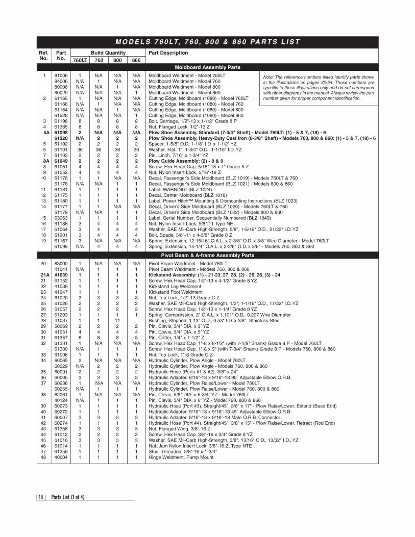
M O D E L S 7 6 0 LT, 7 6 0 , 8 0 0 & 8 6 0 PA R T S L I S T
18 Parts List (1 of 4)
760LT 760 800 860
Note: The reference numbers listed identify parts shownin the illustrations on pages 22-24. These numbers arespecific to these illustrations only and do not correspondwith other diagrams in the manual. Always review the partnumber given for proper component identification.
Moldboard Assembly Parts
Pivot Beam & A-frame Assembly Parts
Ref. Part Build Quantity Part DescriptionNo. No.
1 81006 1 N/A N/A N/A Moldboard Weldment - Model 760LT84006 N/A 1 N/A N/A Moldboard Weldment - Model 76080006 N/A N/A 1 N/A Moldboard Weldment - Model 80080020 N/A N/A N/A 1 Moldboard Weldment - Model 860
2 61165 1 N/A N/A N/A Cutting Edge, Moldboard (1080) - Model 760LT61168 N/A 1 N/A N/A Cutting Edge, Moldboard (1080) - Model 76061164 N/A N/A 1 N/A Cutting Edge, Moldboard (1080) - Model 80061528 N/A N/A N/A 1 Cutting Edge, Moldboard (1080) - Model 860
3 61196 8 8 8 8 Bolt, Carriage, 1/2"-13 x 1-1/2" Grade 8 P4 61365 8 8 8 8 Nut, Flanged Lock, 1/2"-13 Z5A 61098 2 N/A N/A N/A Plow Shoe Assembly, Standard (7-3/4" Shaft) - Model 760LT: (1) - 5 & 7, (18) - 6
61220 N/A 2 2 2 Plow Shoe Assembly, Heavy-Duty Cast Iron (8-3/8" Shaft) - Models 760, 800 & 860: (1) - 5 & 7, (18) - 65 61102 2 2 2 2 Spacer, 1-5/8" O.D, 1-1/8" I.D. x 1-1/2" YZ6 61101 36 36 36 36 Washer, Flat, 1", 1-3/4" O.D., 1-1/16" I.D. YZ 7 61103 2 2 2 2 Pin, Linch, 7/16" x 1-3/4" YZ 8A 61049 2 2 2 2 Plow Guide Assembly: (2) - 8 & 98 61051 4 4 4 4 Screw, Hex Head Cap, 5/16"-18 x 1" Grade 5 Z 9 61052 4 4 4 4 Nut, Nylon Insert Lock, 5/16"-18 Z
10 61176 1 1 N/A N/A Decal, Passenger’s Side Moldboard (BLZ 1019) - Models 760LT & 76061178 N/A N/A 1 1 Decal, Passenger’s Side Moldboard (BLZ 1021) - Models 800 & 860
11 61181 1 1 1 1 Label, WARNING! (BLZ 1024)12 61175 1 1 1 1 Decal, Center Moldboard (BLZ 1018)13 61180 1 1 1 1 Label, Power Hitch™ Mounting & Dismounting Instructions (BLZ 1023)14 61177 1 1 N/A N/A Decal, Driver’s Side Moldboard (BLZ 1020) - Models 760LT & 760
61179 N/A N/A 1 1 Decal, Driver’s Side Moldboard (BLZ 1022) - Models 800 & 86015 63063 1 1 1 1 Label, Serial Number, Sequentially Numbered (BLZ 1049)16 61188 3 4 4 4 Nut, Nylon Insert Lock, 5/8"-11 Type NE17 61064 3 4 4 4 Washer, SAE Mil-Carb High-Strength, 5/8", 1-5/16" O.D., 21/32" I.D. YZ18 61201 3 4 4 4 Bolt, Spade, 5/8"-11 x 4-3/8" Grade 8 Z19 61167 3 N/A N/A N/A Spring, Extension, 12-15/16" O.A.L. x 2-3/8" O.D. x 3/8" Wire Diameter - Model 760LT
61099 N/A 4 4 4 Spring, Extension, 15-1/4" O.A.L. x 2-3/8" O.D. x 3/8" - Models 760, 800 & 860
20 83000 1 N/A N/A N/A Pivot Beam Weldment - Model 760LT41041 N/A 1 1 1 Pivot Beam Weldment - Models 760, 800 & 860
21A 41039 1 1 1 1 Kickstand Assembly: (1) - 21-23, 27, 28, (2) - 25, 26, (3) - 24 21 61152 1 1 1 1 Screw, Hex Head Cap, 1/2"-13 x 4-1/2" Grade 8 YZ22 41038 1 1 1 1 Kickstand Leg Weldment 23 41047 1 1 1 1 Kickstand Foot Weldment24 61020 3 3 3 3 Nut, Top Lock, 1/2"-13 Grade C Z 25 61026 2 2 2 2 Washer, SAE Mil-Carb High-Strength, 1/2", 1-1/16" O.D., 17/32" I.D. YZ26 61057 2 2 2 2 Screw, Hex Head Cap, 1/2"-13 x 1-1/4" Grade 8 YZ27 61293 1 1 1 1 Spring, Compression, 2" O.A.L. x 1.101" O.D., 0.207 Wire Diameter 28 41037 1 1 11 Bushing, Stepped, 1.13" O.D., 0.53" I.D. x 3/8", Stainless Steel29 50069 2 2 2 2 Pin, Clevis, 3/4" DIA. x 3" YZ30 41051 4 4 4 4 Pin, Clevis, 3/4" DIA. x 5" YZ31 61357 8 8 8 8 Pin, Cotter, 1/4" x 1-1/2" Z32 61331 1 N/A N/A N/A Screw, Hex Head Cap, 1"-8 x 8-1/2" (with 7-1/8" Shank) Grade 8 P - Model 760LT
61330 N/A 1 1 1 Screw, Hex Head Cap, 1"-8 x 9" (with 7-3/4" Shank) Grade 8 P - Models 760, 800 & 86033 61008 1 1 1 1 Nut, Top Lock, 1"-8 Grade C Z 34 60065 2 N/A N/A N/A Hydraulic Cylinder, Plow Angle - Model 760LT
60029 N/A 2 2 2 Hydraulic Cylinder, Plow Angle - Models 760, 800 & 86035 60091 2 2 2 2 Hydraulic Hose (Ports #1 & #2), 3/8" x 24"36 60005 3 3 3 3 Hydraulic Adapter, 9/16"-18 x 9/16"-18 90˚ Adjustable Elbow O.R.B.37 60236 1 N/A N/A N/A Hydraulic Cylinder, Plow Raise/Lower - Model 760LT
60255 N/A 1 1 1 Hydraulic Cylinder, Plow Raise/Lower - Model 760, 800 & 86038 82061 1 N/A N/A N/A Pin, Clevis, 5/8" DIA. x 5-3/4" YZ - Model 760LT
40124 N/A 1 1 1 Pin, Clevis, 3/4" DIA. x 6" YZ - Model 760, 800 & 86039 60273 1 1 1 1 Hydraulic Hose (Port #3), Straight/45˚, 3/8" x 17" - Plow Raise/Lower, Extend (Base End)40 60272 1 1 1 1 Hydraulic Adapter, 9/16"-18 x 9/16"-18 45˚ Adjustable Elbow O.R.B.41 60007 3 3 3 3 Hydraulic Adapter, 9/16"-18 x 9/16"-18 Male O.R.B. Connector 42 60274 1 1 1 1 Hydraulic Hose (Port #4), Straight/45˚, 3/8" x 15" - Plow Raise/Lower, Retract (Rod End)43 61358 3 3 3 3 Nut, Flanged Wing, 3/8"-16 Z44 61012 2 2 2 2 Screw, Hex Head Cap, 3/8"-16 x 3/4" Grade 8 YZ45 61016 3 3 3 3 Washer, SAE Mil-Carb High-Strength, 3/8", 13/16" O.D., 13/32" I.D., YZ46 61014 1 1 1 1 Nut, Jam Nylon Insert Lock, 3/8"-16 Z, Type NTE47 61359 1 1 1 1 Stud, Threaded, 3/8"-16 x 1-3/4"48 40004 1 1 1 1 Hinge Weldment, Pump Mount
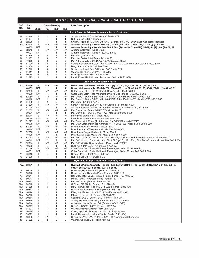
M O D E L S 7 6 0 LT, 7 6 0 , 8 0 0 & 8 6 0 PA R T S L I S T
Parts List (2 of 4) 19
760LT 760 800 860Pivot Beam & A-frame Assembly Parts (Continued)
Draw Latch Assembly Parts
Hydraulic Pump & Manifold Assembly Parts
Ref. Part Build Quantity Part DescriptionNo. No.
49 61218 1 1 1 1 Screw, Hex Head Cap, 3/8"-16 x 2" Grade 8 YZ 50 61034 1 1 1 1 Nut, Top Lock, 3/8"-16 Grade C Z 51 62038 1 1 1 1 Switch, Toggle, DPDT, (On)-Off-(On), 16 Amps, 115V AC - Draw Latch Connect/Disconnect52A 82048 1 N/A N/A N/A A-frame Assembly - Model 760LT: (1) - 48-50, 52 (82043), 55-57, 61, (2) - 60, (4) - 58, 59
40105 N/A 1 1 1 A-frame Assembly - Models 760, 800 & 860: (1) - 48-50, 52 (40091), 55-57, 61, (2) - 60, (4) - 58, 5952 82043 1 N/A N/A N/A A-frame Weldment - Model 760LT
40091 N/A 1 1 1 A-frame Weldment - Models 760, 800 & 86053 61426 3 3 3 3 Pin, Hitch, 3/4" x 6" YZ54 61105 3 3 3 3 Pin, Hair Cotter, 9/64" DIA. x 2-11/16" Z55 40079 3 3 3 3 Pin, A-frame Latch, 3/8" DIA. x 1-3/4", Stainless Steel56 61000 3 3 3 3 Spring, Compression, 0.94" O.A.F.L. x 0.36" O.D., 0.029" Wire Diameter, Stainless Steel57 61309 3 3 3 3 Ring, Standard Split, Stainless Steel58 61312 4 4 4 4 Screw, Hex Head Cap, 5/16"-18 x 3/4" Grade 8 YZ59 61011 4 4 4 4 Washer, Split Lock, 5/16" YZ High-Alloy 60 40088 2 2 2 2 Bushing, A-frame Pivot, Replaceable61 61295 1 1 1 1 Label, Power Hitch Connect/Disconnect Switch (BLZ 1037)
62A 82049 1 N/A N/A N/A Draw Latch Assembly - Model 760LT: (1) - 31, 62, 63, 65, 66, 68-76, (2) - 64 & 6740109 N/A 1 1 1 Draw Latch Assembly - Models 760, 800 & 860: (1) - 31, 62, 63, 65, 66, 68-70, 72-76, (2) - 64, 67, 71
62 82035 1 N/A N/A N/A Outer Draw Latch Plate Weldment, Driver’s Side - Model 760LT40080 N/A 1 1 1 Outer Draw Latch Plate Weldment, Driver’s Side - Models 760, 800 & 860
63 82050 1 N/A N/A N/A Pin, Draw, 1" DIA. x 5-5/8" (with 13/64" DIA. Cotter Pin Hole) BZ - Model 760LT40110 N/A 1 1 1 Pin, Draw, 1" DIA. x 6-1/2" (with 13/64" DIA. Cotter Pin Hole) YZ - Models 760, 800 & 860
64 61363 2 2 2 2 Pin, Cotter, 3/16" x 2-1/2" Z65 61200 1 N/A N/A N/A Screw, Hex Head Cap, 3/4"-10 x 4" Grade 8 YZ - Model 760LT
61004 N/A 1 1 1 Screw, Hex Head Cap, 3/4"-10 x 4-1/2" Grade 8 YZ - Models 760, 800 & 86066 82055 1 N/A N/A N/A Pin, Clevis, 3/4" DIA. x 3-7/16" BZ - Model 760LT
50071 N/A 1 1 1 Pin, Clevis, 3/4" DIA. x 3-41/64" YZ - Models 760, 800 & 86067 82014 2 N/A N/A N/A Inner Draw Latch Plate - Model 760LT
40074 N/A 2 2 2 Inner Draw Latch Plate - Models 760, 800 & 86068 82027 1 N/A N/A N/A Pin, Draw Latch Mount (To A-frame), 1" x 3-7/8" BZ - Model 760LT
40070 N/A 1 1 1 Pin, Draw Latch Mount (To A-frame), 1" x 4-21/32" YZ - Models 760, 800 & 86069 82054 1 N/A N/A N/A Draw Latch Arm Weldment - Model 760LT
40114 N/A 1 1 1 Draw Latch Arm Weldment - Models 760, 800 & 86070 82058 1 N/A N/A N/A Draw Latch Finger Weldment - Model 760LT
40123 N/A 1 1 1 Draw Latch Finger Weldment - Models 760, 800 & 86071 82033 1 N/A N/A N/A Pin, 5/8" x 2-3/8" BZ, Inner Draw Latch Plate/Hyd. Cyl. Rod End, Plow Raise/Lower - Model 760LT
40042 N/A 2 2 2 Pin, 3/4" x 2-1/2", Draw Latch Arm Pivot Pin/Hyd. Cyl. Rod End, Plow Raise/Lower - Models 760, 800 & 86072 82024 1 N/A N/A N/A Pin, 3/4" x 2-3/8" Draw Latch Arm Pivot - Model 760LT73 40093 1 1 1 1 Bushing, 1-1/4" O.D., 1-1/16" I.D. x 1-1/2" YZ74 82036 1 N/A N/A N/A Outer Draw Latch Plate Weldment, Passenger’s Side - Model 760LT
40081 N/A 1 1 1 Outer Draw Latch Plate Weldment, Passenger’s Side - Models 760, 800 & 86075 40116 1 1 1 1 Spacer, 1" O.D., 25/32" I.D. x 5/8" YZ76 61006 1 1 1 1 Nut, Top Lock, 3/4"-10 Grade C Z
77A 60101 1 1 1 1 Hydraulic Pump Assembly (Fenner Fluid Power-DB1484): (1) - 77-80, 60312, 60215, 61268, 60313,60128, 60218, 60314, 60315, 60316 & 60317
77 60045 1 1 1 1 Reservoir, Hydraulic Pump (Fenner - 3853-AC)78 60046 1 1 1 1 Reservoir Cap, Hydraulic Pump (Fenner - 8060-CC)79 60044 1 1 1 1 Hex Cap, Relief Valve, Hydraulic Pump (Fenner - S3-1015-07)80 60047 1 1 1 1 Motor, 12VDC, Hydraulic Pump (Fenner - 1787-AC)N/A 60312 1 1 1 1 Pin, 1/8" x 1/4" (Fenner - F6-4000-25)N/A 60215 1 1 1 1 O-Ring, -348 Nitrile (Fenner - G1-1073-48)N/A 61268 4 4 4 4 Bolt, Hex Washer Head, #12-24 x 0.50 (Fenner - 3346-AA)N/A 60313 1 1 1 1 Pump Assembly, Short Spline (Fenner - PS-2.5)N/A 60128 1 1 1 1 Filter, 149 Micron, 1.5" x 1.0" L2574 (Fenner - 4303-AA)N/A 60218 1 1 1 1 Elbow, Nylon, X-111 (Fenner - T2-5001-00)N/A 60314 1 1 1 1 Coupling, SAE 9T-20/40 1.260" (Fenner - 1118-AA)N/A 60315 1 1 1 1 Spring, RV 3000-4000 PSI, Black (Fenner - C1-1009-01)N/A 60316 1 1 1 1 Adjustment, Valve Screw, B-1 (Fenner - W5-1020-95)N/A 60317 1 1 1 1 Ball, Steel (G50), 0.375" (Fenner - 1172-AA)81 61307 1 1 1 1 Washer, Internal/External Tooth Lock, 3/8" 82 40119 1 1 1 1 Cover, Hydraulic Pump & Manifold, 1/4" Polyethylene83 63099 1 1 1 1 Label, Hydraulic Hose Identification Guide (BLZ 1054)84 60038 2 2 2 2 O-ring, 3/ 32" C.S.W., 9/16" I.D., 3/4" O.D. Neoprene, 70 Durometer 85 61222 2 2 2 2 Washer, Split Lock, 3/8" High-Alloy YZ
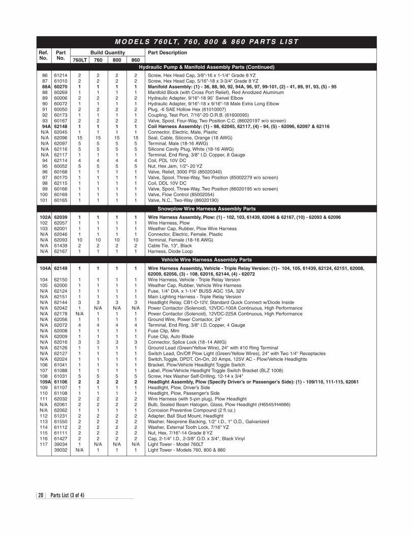
M O D E L S 7 6 0 LT, 7 6 0 , 8 0 0 & 8 6 0 PA R T S L I S T
20 Parts List (3 of 4)
760LT 760 800 860Hydraulic Pump & Manifold Assembly Parts (Continued)
Snowplow Wire Harness Assembly Parts
Vehicle Wire Harness Assembly Parts
Ref. Part Build Quantity Part DescriptionNo. No.
86 61214 2 2 2 2 Screw, Hex Head Cap, 3/8"-16 x 1-1/4" Grade 8 YZ87 61010 2 2 2 2 Screw, Hex Head Cap, 5/16"-18 x 3-3/4" Grade 8 YZ88A 60270 1 1 1 1 Manifold Assembly: (1) - 36, 88, 90, 92, 94A, 96, 97, 99-101, (2) - 41, 89, 91, 93, (5) - 95 88 60269 1 1 1 1 Manifold Block (with Cross Port Relief), Red Anodized Aluminum89 60006 2 2 2 2 Hydraulic Adapter, 9/16"-18 90˚ Swivel Elbow 90 60072 1 1 1 1 Hydraulic Adapter, 9/16"-18 x 9/16"-18 Male Extra Long Elbow91 60050 2 2 2 2 Plug, -6 SAE Hollow Hex (61010007) 92 60173 1 1 1 1 Coupling, Test Port, 7/16"-20 O.R.B. (61600095) 93 60167 2 2 2 2 Valve, Spool, Four-Way, Two Position C.C. (86020197 w/o screen)94A 62148 1 1 1 1 Coil Harness Assembly: (1) - 98, 62045, 62117, (4) - 94, (5) - 62096, 62097 & 62116 N/A 62045 1 1 1 1 Connector, Electric, Male, Plastic N/A 62096 15 15 15 15 Seal, Cable, Silicone, Orange (18 AWG)N/A 62097 5 5 5 5 Terminal, Male (18-16 AWG)N/A 62116 5 5 5 5 Silicone Cavity Plug, White (18-16 AWG)N/A 62117 1 1 1 1 Terminal, End Ring, 3/8" I.D. Copper, 8 Gauge94 62114 4 4 4 4 Coil, PDL 10V DC95 60052 5 5 5 5 Nut, Hex Jam, 1/2"- 20 YZ 96 60168 1 1 1 1 Valve, Relief, 3000 PSI (85020340)97 60170 1 1 1 1 Valve, Spool, Three-Way, Two Position (85002279 w/o screen)98 62115 1 1 1 1 Coil, DDL 10V DC99 60166 1 1 1 1 Valve, Spool, Three-Way, Two Position (86020195 w/o screen)
100 60169 1 1 1 1 Valve, Flow Control (85002054)101 60165 1 1 1 1 Valve, N.C., Two-Way (86020190)
102A 62039 1 1 1 1 Wire Harness Assembly, Plow: (1) - 102, 103, 61439, 62046 & 62167, (10) - 62093 & 62096102 62057 1 1 1 1 Wire Harness, Plow103 62001 1 1 1 1 Weather Cap, Rubber, Plow Wire HarnessN/A 62046 1 1 1 1 Connector, Electric, Female, PlasticN/A 62093 10 10 10 10 Terminal, Female (18-16 AWG)N/A 61439 2 2 2 2 Cable Tie, 13", Black N/A 62167 1 1 1 1 Harness, Diode Loop
104A 62149 1 1 1 1 Wire Harness Assembly, Vehicle - Triple Relay Version: (1) - 104, 105, 61439, 62124, 62151, 62008,62009, 62056, (3) - 108, 62016, 62144, (4) - 62072
104 62150 1 1 1 1 Wire Harness, Vehicle - Triple Relay Version105 62000 1 1 1 1 Weather Cap, Rubber, Vehicle Wire HarnessN/A 62124 1 1 1 1 Fuse, 1/4" DIA. x 1-1/4" BUSS AGC 15A, 32V N/A 62151 1 1 1 1 Main Lighting Harness - Triple Relay VersionN/A 62144 3 3 3 3 Headlight Relay, CB1-D-12V, Standard Quick Connect w/Diode InsideN/A 62042 1 N/A N/A N/A Power Contactor (Solenoid), 12VDC-100A Continuous, High Performance N/A 62178 N/A 1 1 1 Power Contactor (Solenoid), 12VDC-225A Continuous, High PerformanceN/A 62056 1 1 1 1 Ground Wire, Power Contactor, 24"N/A 62072 4 4 4 4 Terminal, End Ring, 3/8" I.D. Copper, 4 Gauge N/A 62008 1 1 1 1 Fuse Clip, Mini N/A 62009 1 1 1 1 Fuse Clip, Auto Blade N/A 62016 3 3 3 3 Connector, Splice Lock (18 -14 AWG)N/A 62126 1 1 1 1 Ground Lead (Green/Yellow Wire), 24" with #10 Ring TerminalN/A 62127 1 1 1 1 Switch Lead, On/Off Plow Light (Green/Yellow Wires), 24" with Two 1/4" ReceptaclesN/A 62024 1 1 1 1 Switch,Toggle, DPDT, On-On, 20 Amps, 125V AC - Plow/Vehicle Headlights106 61041 1 1 1 1 Bracket, Plow/Vehicle Headlight Toggle Switch107 61088 1 1 1 1 Label, Plow/Vehicle Headlight Toggle Switch Bracket (BLZ 1008)108 61031 5 5 5 5 Screw, Hex Washer Self-Drilling, 12-14 x 3/4"109A 61106 2 2 2 2 Headlight Assembly, Plow (Specify Driver’s or Passenger’s Side): (1) - 109/110, 111-115, 62061109 61107 1 1 1 1 Headlight, Plow, Driver’s Side110 61108 1 1 1 1 Headlight, Plow, Passenger’s Side111 62032 2 2 2 2 Wire Harness (with 5-pin plug), Plow HeadlightN/A 62061 2 2 2 2 Bulb, Sealed Beam Halogen, Glass, Plow Headlight (H6545/H4666)N/A 62062 1 1 1 1 Corrosion Preventive Compound (2 fl.oz.)112 61231 2 2 2 2 Adapter, Ball Stud Mount, Headlight113 61550 2 2 2 2 Washer, Neoprene Backing, 1/2" I.D., 1" O.D., Galvanized114 61112 2 2 2 2 Washer, External Tooth Lock, 7/16" YZ 115 61111 2 2 2 2 Nut, Hex, 7/16"-14 Grade 8 YZ116 61427 2 2 2 2 Cap, 2-1/4" I.D., 2-3/8" O.D. x 3/4", Black Vinyl117 39034 1 N/A N/A N/A Light Tower - Model 760LT
39032 N/A 1 1 1 Light Tower - Models 760, 800 & 860
Ref. Part Build Quantity Part DescriptionNo. No.
118A 62073 1 1 1 1 Control Station Assembly, Joystick: (1) - 118, 119 & 123 118 62074 1 1 1 1 Control Station, Joystick119 63106 1 1 1 1 Label, Plow Power Switch, On/Off (BLZ 1061)120 61185 1 1 1 1 Base Plate, 1/8" ABS Plastic, Joystick Control Station121 61127 1 1 1 1 Strap (Velcro® with 2" Metal D-Ring), Black, 61" 122 61254 4 4 4 4 Screw, Pan Head Machine, 8-32 x 3/4" Z123 61174 1 1 1 1 Label, Control Station, Joystick (BLZ 1017)124 30042 N/A 1 1 1 Undercarriage Weldment, 1999-Current, Chevrolet/GMC 2500 Series125 61128 1 N/A N/A N/A Decal, Undercarriage Push Beam, 1-1/2" x 9-1/4" (BLZ 1004)126 61085 N/A 1 1 1 Decal, Undercarriage Push Beam, 2-1/4" x 13-7/8" (BLZ 1003)
N/A 61354 1 N/A N/A N/A Kit, Hardware, Snowplow Assembly Parts - Model 760LT: (1) 45-47, 81, (2) 29, 44, (3) 16-18, 43, (4) 30, (6) 31N/A 61353 N/A 1 1 1 Kit, Hardware, Snowplow Assembly Parts - Models 760, 800 & 860: (1) 45-47, 81, (2) 29, 44, (3) 43,
(4) 16-18, 30, (6) 31 N/A 60276 1 1 1 1 Kit, Hydraulic Adapter: (1) 40 & 90, (2) 89, (3) 36 & 41N/A 60281 1 1 1 1 Kit, Hydraulic Hose: (1) 39 & 42, (2) 35 N/A 61255 1 1 1 1 Kit, Hardware, Moldboard Cutting Edge: (8) 3 & 4 N/A 61256 1 N/A N/A N/A Cutting Edge (with Hardware Kit), Moldboard - Model 760LT: (1) - 61165, 61255N/A 61258 N/A 1 N/A N/A Cutting Edge (with Hardware Kit), Moldboard - Model 760: (1) - 61168, 61255 N/A 61259 N/A N/A 1 N/A Cutting Edge (with Hardware Kit), Moldboard - Model 800: (1) - 61164, 61255 N/A 61532 N/A N/A N/A 1 Cutting Edge (with Hardware Kit), Moldboard - Model 860: (1) - 61528, 61255
Parts List (4 of 4) 21
M O D E L S 7 6 0 LT, 7 6 0 , 8 0 0 & 8 6 0 PA R T S L I S T
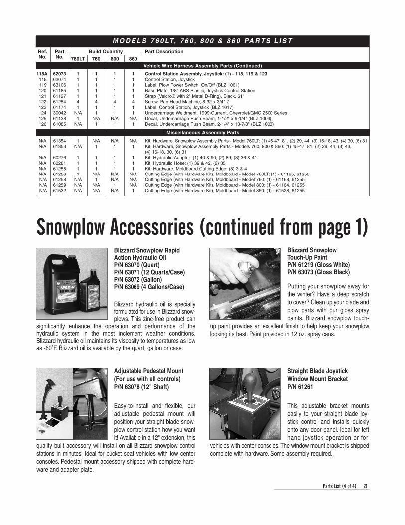
760LT 760 800 860Vehicle Wire Harness Assembly Parts (Continued)
Miscellaneous Assembly Parts
Blizzard Snowplow Touch-Up PaintP/N 61219 (Gloss White)P/N 63073 (Gloss Black)
Putting your snowplow away forthe winter? Have a deep scratchto cover? Clean up your blade andplow parts with our gloss spraypaints. Blizzard snowplow touch-
up paint provides an excellent finish to help keep your snowplowlooking its best. Paint provided in 12 oz. spray cans.
Blizzard Snowplow RapidAction Hydraulic OilP/N 63070 (Quart)P/N 63071 (12 Quarts/Case)P/N 63072 (Gallon)P/N 63069 (4 Gallons/Case)
Blizzard hydraulic oil is speciallyformulated for use in Blizzard snow-plows. This zinc-free product can
significantly enhance the operation and performance of thehydraulic system in the most inclement weather conditions.Blizzard hydraulic oil maintains its viscosity to temperatures as lowas -60˚F. Blizzard oil is available by the quart, gallon or case.
Snowplow Accessories (continued from page 1)
Straight Blade Joystick Window Mount BracketP/N 61261
This adjustable bracket mountseasily to your straight blade joy-stick control and installs quicklyonto any door panel. Ideal for lefthand joystick operation or for
vehicles with center consoles. The window mount bracket is shippedcomplete with hardware. Some assembly required.
Adjustable Pedestal Mount(For use with all controls) P/N 63078 (12" Shaft)
Easy-to-install and flexible, ouradjustable pedestal mount willposition your straight blade snow-plow control station how you wantit! Available in a 12" extension, this
quality built accessory will install on all Blizzard snowplow controlstations in minutes! Ideal for bucket seat vehicles with low centerconsoles. Pedestal mount accessory shipped with complete hard-ware and adapter plate.
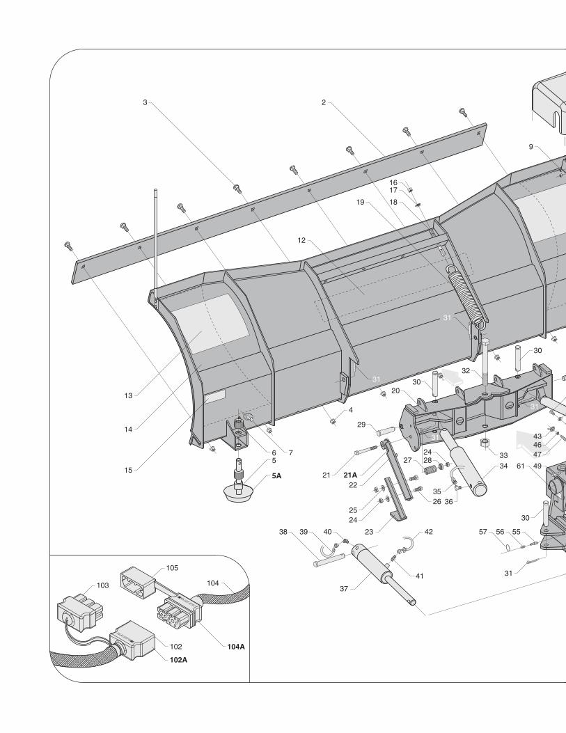
23
4
5A
56 7
9
12
14
15
16
19
17
18
20
21A2122
23
2524
26
27 2824
29
30
30
30
31
31
31
31
3132
3334
3536
37
38 39 40
41
42
434647
49
555657
61
102A
102
103
104A
104
105
13
1
8A
8
10
29
30
31
31
31
34
35
36
43
43
44
44
4545
45
48
50 51
52A52
53
54
555556
56
57
57
59
59
58
60
62A62
63
64
6566
67 68
69
70
71/72
7173
75
76
77A77
78
79
80
81
82
83
84
85 85
87
88A - SEE DETAIL ON PAGE 24.
86
86
106107
108
109A
109 110
111
112
114
116
115
117
118A
120
121
122
123
124
125/126
11
53 7464
113
119118
24 Manifold Detail w/Hydraulic & Electrical Schematics
88
36
92
91
93
94
95
96
93
94
97
98 99
94
95
94
100
91
101
89
90
ABCDEFGHJK
S5
S4
S8
S3
S6
S5
S8S4
S3
S6
CONNECTS TO PACKARD ELECTRIC CONNECTORSEE SCHEMATIC ON PAGE 27.
N/A
N/A
N/A
N/A
N/A
RIGHT ANGLE
LEFT ANGLE
3000 PSI1
RV
2
S3 S4
TGP
PGP
S6
T1 P1
S5
S8
FC
RAISE LOWER3 4
LIFT CYL.
8941
94A
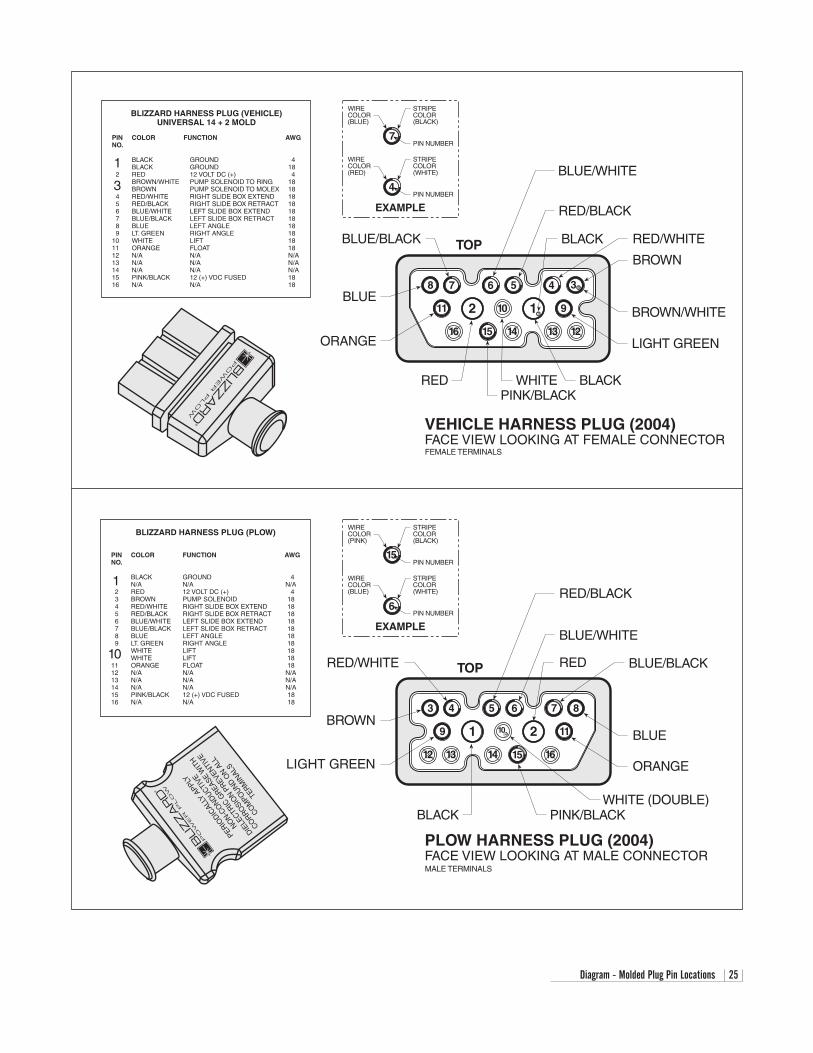
Diagram - Molded Plug Pin Locations 25
BLUE/BLACK
PLOW HARNESS PLUG (2004)FACE VIEW LOOKING AT MALE CONNECTOR
VEHICLE HARNESS PLUG (2004)FACE VIEW LOOKING AT FEMALE CONNECTOR
BLIZZARD HARNESS PLUG (PLOW)
PIN COLOR FUNCTION AWGNO.
BLACK GROUND 4N/A N/A N/A
2 RED 12 VOLT DC (+) 43 BROWN PUMP SOLENOID 184 RED/WHITE RIGHT SLIDE BOX EXTEND 185 RED/BLACK RIGHT SLIDE BOX RETRACT 186 BLUE/WHITE LEFT SLIDE BOX EXTEND 187 BLUE/BLACK LEFT SLIDE BOX RETRACT 188 BLUE LEFT ANGLE 189 LT. GREEN RIGHT ANGLE 18
WHITE LIFT 18WHITE LIFT 18
11 ORANGE FLOAT 1812 N/A N/A N/A13 N/A N/A N/A14 N/A N/A N/A15 PINK/BLACK 12 (+) VDC FUSED 1816 N/A N/A 18
BLIZZARD HARNESS PLUG (VEHICLE)UNIVERSAL 14 + 2 MOLD
PIN COLOR FUNCTION AWGNO.
BLACK GROUND 4BLACK GROUND 18
2 RED 12 VOLT DC (+) 4BROWN/WHITE PUMP SOLENOID TO RING 18BROWN PUMP SOLENOID TO MOLEX 18
4 RED/WHITE RIGHT SLIDE BOX EXTEND 185 RED/BLACK RIGHT SLIDE BOX RETRACT 186 BLUE/WHITE LEFT SLIDE BOX EXTEND 187 BLUE/BLACK LEFT SLIDE BOX RETRACT 188 BLUE LEFT ANGLE 189 LT. GREEN RIGHT ANGLE 18
10 WHITE LIFT 1811 ORANGE FLOAT 1812 N/A N/A N/A13 N/A N/A N/A14 N/A N/A N/A15 PINK/BLACK 12 (+) VDC FUSED 1816 N/A N/A 18
1
3
FEMALE TERMINALS
MALE TERMINALS
4
STRIPECOLOR(BLACK)
WIRECOLOR(BLUE)
PIN NUMBER
STRIPECOLOR(WHITE)
WIRECOLOR(RED)
PIN NUMBER
EXAMPLE
7
1
6
15
STRIPECOLOR(BLACK)
WIRECOLOR(PINK)
PIN NUMBER
STRIPECOLOR(WHITE)
WIRECOLOR(BLUE)
PIN NUMBER
EXAMPLE
10
4
15
10
BLACK RED/WHITE
LIGHT GREEN
TOP
WHITERED
BLUE
ORANGE
BLUE/WHITE
RED/BLACK
PINK/BLACK
BROWN/WHITE
8 37 56
11 9
BROWN
12
1216 1314
BLACK
1
3
6 7
9 1 210 11
TOPRED/WHITE
BLUE/WHITE
RED/BLACK
BROWN
LIGHT GREEN
BLACK
RED
BLUE
ORANGE
PINK/BLACK
15
WHITE (DOUBLE)
BLUE/BLACK
3 854
10
1612 13 14
PERIO
DICAL
LY A
PPLY
NON-C
ONDUCTI
VE
DIELE
CTRIC
GREA
SE W
ITH
CORRO
SIO
N PREV
ENTI
VE
COM
POUND O
N ALL
TERM
INAL
S
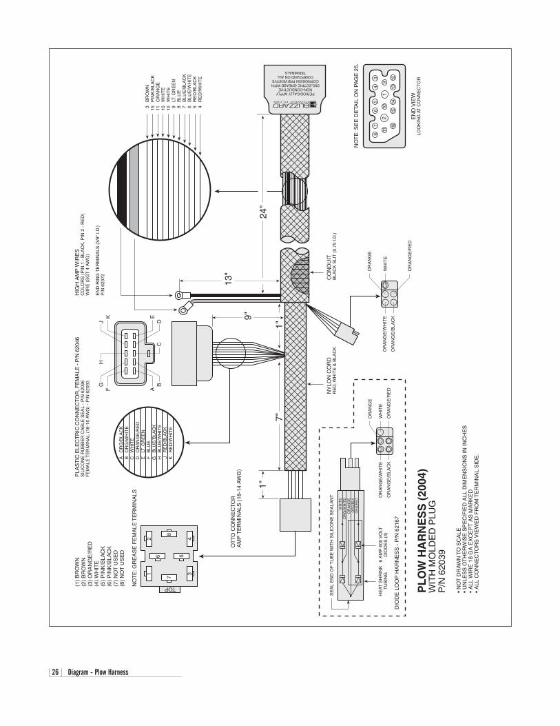
26 Diagram - Plow Harness
24"
3B
RO
WN
15P
INK
/BLA
CK
11O
RA
NG
E10
WH
ITE
10W
HIT
E9
LT. G
RE
EN
8B
LUE
7B
LUE
/BLA
CK
6B
LUE
/WH
ITE
5R
ED
/BLA
CK
4R
ED
/WH
ITE
HIG
H A
MP
WIR
ES
CO
LOR
S (
PIN
1 -
BLA
CK
, PIN
2 -
RE
D)
WIR
E (
SG
T 4
AW
G)
EN
D R
ING
TE
RM
INA
LS (
3/8"
I.D
.)P
/N 6
2072
EN
D V
IEW
LOO
KIN
G A
T C
ON
NE
CT
OR
NO
TE
: SE
E D
ETA
IL O
N P
AG
E 2
5.
87
11
16
21
65
43
910
1514
1312
13"
CO
ND
UIT
BLA
CK
SLI
T (
0.75
I.D
.)N
YLO
N C
OR
DR
ED
, WH
ITE
& B
LAC
K
PERIODICALLY APPLYNON-CONDUCTIVE
DIELECTRIC GREASE WITHCORROSION PREVENTIVE
COMPOUND ON ALLTERMINALS
9"
1"7"
FG
HJ
K
AB
CD
E
AO
RG
/BLA
CK
BO
RG
/WH
ITE
CW
HIT
ED
OR
AN
GE
/RE
DE
LT. G
RE
EN
FB
LUE
GB
LUE
/BLA
CK
HB
LUE
/WH
ITE
JR
ED
/BLA
CK
KR
ED
/WH
ITE
1"
PL
OW
HA
RN
ES
S (
2004
)W
ITH
MO
LDE
D P
LUG
P/N
620
39
• N
OT
DR
AW
N T
O S
CA
LE•
UN
LES
S O
TH
ER
WIS
E S
PE
CIF
IED
ALL
DIM
EN
SIO
NS
IN IN
CH
ES
•A
LL W
IRE
18
GA
EX
CE
PT
AS
MA
RK
ED
• A
LL C
ON
NE
CTO
RS
VIE
WE
D F
RO
M T
ER
MIN
AL
SID
E.
1
TOP(1)
BR
OW
N(2
)B
RO
WN
(3)
OR
AN
GE
/RE
D(4
)W
HIT
E(5
)P
INK
/BLA
CK
(6)
PIN
K/B
LAC
K(7
)N
OT
US
ED
(8)
NO
T U
SE
D
NO
TE
: GR
EA
SE
FE
MA
LE T
ER
MIN
ALS
OT
TO C
ON
NE
CTO
RA
MP
TE
RM
INA
LS (
18-1
4 A
WG
)
PLA
ST
IC E
LEC
TR
IC C
ON
NE
CTO
R, F
EM
ALE
- P
/N 6
2046
SIL
ICO
NE
RU
BB
ER
CA
BLE
SE
AL
- P
/N 6
2096
FE
MA
LE T
ER
MIN
AL
(18-
16 A
WG
) -
P/N
620
93
6
7
2
8
3
5
4
OR
AN
GE
WH
ITE
OR
AN
GE
/RE
D
OR
AN
GE
/WH
ITE
OR
AN
GE
/BLA
CK
DIO
DE
LO
OP
HA
RN
ES
S -
P/N
621
67
WH
ITE
OR
G/W
HIT
EO
RA
NG
E
HE
AT S
HR
INK
TU
BIN
G6
AM
P 6
00 V
OLT
DIO
DE
S (
4)
OR
AN
GE
OR
AN
GE
/WH
ITE
OR
AN
GE
/BLA
CK
SE
AL
EN
D O
F T
UB
E W
ITH
SIL
ICO
NE
SE
ALA
NT
WH
ITE
OR
AN
GE
/RE
D
OR
G/B
LKO
RG
/RE
D
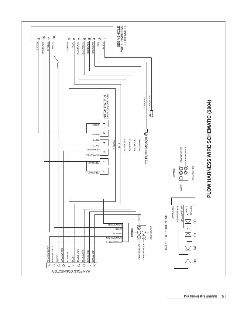
Plow Harness Wire Schematic 27
PL
OW
HA
RN
ES
S W
IRE
SC
HE
MA
TIC
(20
04)
A B C D E F G H J K
OR
AN
GE
/BLA
CK
OR
AN
GE
/WH
ITE
WH
ITE
OR
AN
GE
/RE
D
LT. G
RE
EN
BLU
E
BLU
E/B
LAC
K
BLU
E/W
HIT
E
RE
D/B
LAC
K
RE
D/W
HIT
E
MANIFOLD CONNECTOR
ORANGE/WHITE
ORANGE/BLACK
ORANGE
WHITE
ORANGE/RED
65
34
21
PINK/BLACK
PINK/BLACK
ORANGE/RED
ORANGE/RED
WHITE
WHITE
BROWN
BROWN
HIT
CH
SW
ITC
HD
PD
T (
ON
)-O
FF
-(O
N)
BR
OW
N
PIN
K/B
LAC
K
OR
AN
GE
WH
ITE
WH
ITE
1011153
SE
E V
EH
ICLE
WIR
E H
AR
NE
SS
SC
HE
MAT
IC
LT. G
RE
EN
BLU
E
BLU
E/B
LAC
K
BLU
E/W
HIT
E
RE
D/B
LAC
K
RE
D/W
HIT
E
RE
D
BLA
CK
12456789
4 G
A, R
ED
4 G
A, B
LAC
KTO
PU
MP
MO
TOR
LT. G
RE
EN
BLU
E
BLU
E/B
LAC
K
BLU
E/W
HIT
E
RE
D/B
LAC
K
RE
D/W
HIT
E
OR
AN
GE
OR
AN
GE
/WH
ITE
OR
AN
GE
/BLA
CK
WH
ITE
OR
AN
GE
OR
AN
GE
/RE
D
DIO
DE
LO
OP
HA
RN
ES
S
OR
AN
GE
/RE
D
OR
AN
GE
/BLA
CK
OR
AN
GE
/WH
ITE
WH
ITE
OR
AN
GE
D3
D1
D2
D4
OR
AN
GE
OR
AN
GE
/RE
D
OR
AN
GE
/WH
ITE
OR
AN
GE
/BLA
CK
WH
ITE
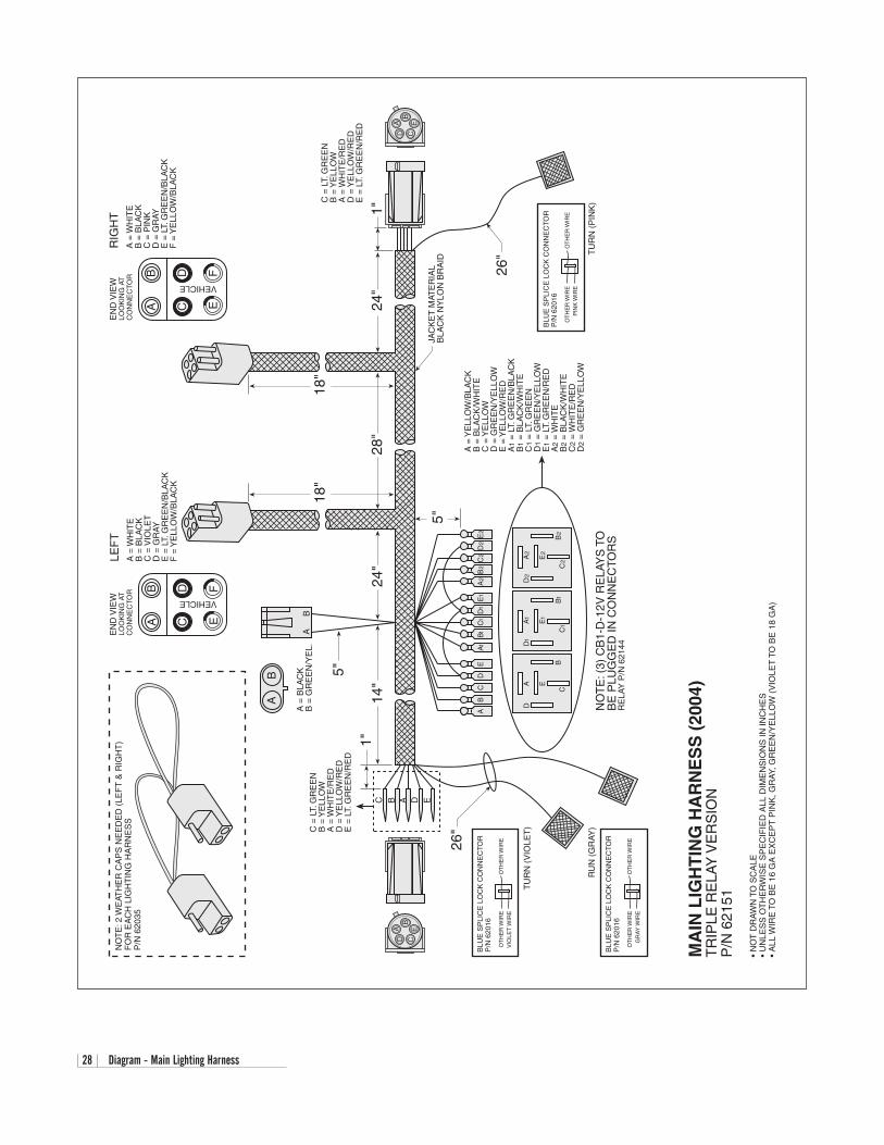
28 Diagram - Main Lighting Harness
RIG
HT
C =
LT.
GR
EE
NB
= Y
ELL
OW
A =
WH
ITE
/RE
DD
= Y
ELL
OW
/RE
DE
= L
T. G
RE
EN
/RE
D AB
CD
E
26" T
UR
N (
PIN
K)
BLU
E S
PLI
CE
LO
CK
CO
NN
EC
TOR
P/N
620
16
OT
HE
R W
IRE
PIN
K W
IRE
OT
HE
R W
IRE
24"
1"
18"
A =
WH
ITE
B =
BLA
CK
C =
VIO
LET
D =
GR
AYE
= L
T. G
RE
EN
/BLA
CK
F =
YE
LLO
W/B
LAC
K
LEF
T
JAC
KE
T M
ATE
RIA
LB
LAC
K N
YLO
N B
RA
ID
28"
24"
14"
AB
CD
E
1"
26"
TU
RN
(V
IOLE
T)
BLU
E S
PLI
CE
LO
CK
CO
NN
EC
TOR
P/N
620
16
OT
HE
R W
IRE
VIO
LET
WIR
EO
TH
ER
WIR
E
BLU
E S
PLI
CE
LO
CK
CO
NN
EC
TOR
P/N
620
16
OT
HE
R W
IRE
GR
AY W
IRE
OT
HE
R W
IRE
RU
N (
GR
AY)
C B A D E
C =
LT.
GR
EE
NB
= Y
ELL
OW
A =
WH
ITE
/RE
DD
= Y
ELL
OW
/RE
DE
= L
T. G
RE
EN
/RE
D
DA E
CB
A1
D1
E1
C1
B1
A2
D2
E2
C2
B2
A =
YE
LLO
W/B
LAC
KB
= B
LAC
K/W
HIT
EC
= Y
ELL
OW
D =
GR
EE
N/Y
ELL
OW
E =
YE
LLO
W/R
ED
A1
= L
T. G
RE
EN
/BLA
CK
B1
= B
LAC
K/W
HIT
EC
1 =
LT.
GR
EE
ND
1 =
GR
EE
N/Y
ELL
OW
E1
= L
T. G
RE
EN
/RE
DA
2 =
WH
ITE
B2
= B
LAC
K/W
HIT
EC
2 =
WH
ITE
/RE
DD
2 =
GR
EE
N/Y
ELL
OW
NO
TE
: (3)
CB
1-D
-12V
RE
LAY
S T
OB
E P
LUG
GE
D IN
CO
NN
EC
TOR
SR
ELA
Y P
/N 6
2144
MA
IN L
IGH
TIN
G H
AR
NE
SS
(20
04)
TR
IPLE
RE
LAY
VE
RS
ION
P/N
621
51
• N
OT
DR
AW
N T
O S
CA
LE•
UN
LES
S O
TH
ER
WIS
E S
PE
CIF
IED
ALL
DIM
EN
SIO
NS
IN IN
CH
ES
•A
LL W
IRE
TO
BE
16
GA
EX
CE
PT
PIN
K, G
RAY
, GR
EE
N/Y
ELL
OW
(V
IOLE
T T
O B
E 1
8 G
A)
5"
NO
TE
: 2 W
EAT
HE
R C
AP
S N
EE
DE
D (
LEF
T &
RIG
HT
)F
OR
EA
CH
LIG
HT
ING
HA
RN
ES
SP
/N 6
2035
18"
AB
CD F
VEHICLE
EN
D V
IEW
LOO
KIN
G A
TC
ON
NE
CTO
R
E
AB
CD F
VEHICLE
EN
D V
IEW
LOO
KIN
G A
TC
ON
NE
CTO
R
E
A =
WH
ITE
B =
BLA
CK
C =
PIN
KD
= G
RAY
E =
LT.
GR
EE
N/B
LAC
KF
= Y
ELL
OW
/BLA
CK
A =
BLA
CK
B =
GR
EE
N/Y
EL.
5"
AB
CD
EA1
B1C
1D
1E
1A
2B
2C
2D
2E
2
BA
AB
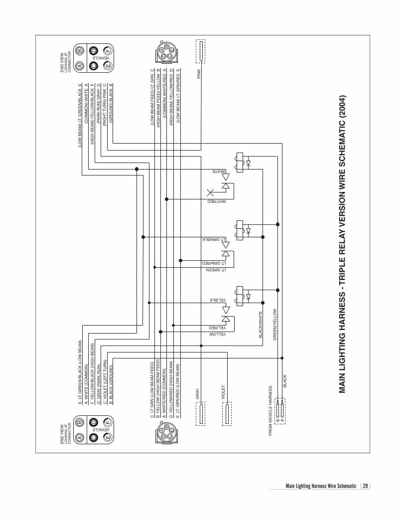
Main Lighting Harness Wire Schematic 29
MA
IN L
IGH
TIN
G H
AR
NE
SS
- T
RIP
LE
RE
LA
Y V
ER
SIO
N W
IRE
SC
HE
MA
TIC
(20
04)
AB
CD F
VEHICLE
EN
D V
IEW
LOO
KIN
G A
TC
ON
NE
CTO
R
E
E L
T. G
RE
EN
/BLA
CK
(LO
W B
EA
M)
A W
HIT
E (
CO
MM
ON
)
F Y
ELL
OW
/BLA
CK
(H
IGH
BE
AM
)
D G
RAY
(PA
RK
-RU
N)
C V
IOLE
T (
LEF
T T
UR
N)
B B
LAC
K (
GR
OU
ND
)
(LO
W B
EA
M)
LT. G
RE
EN
/BLA
CK
E
(CO
MM
ON
) WH
ITE
A
(HIG
H B
EA
M) Y
ELL
OW
/BLA
CK
F
(PA
RK
-RU
N)
GR
AY D
(RIG
HT
TU
RN
) P
INK
C
(GR
OU
ND
) B
LAC
K B
AB
CD F
VEHICLE
EN
D V
IEW
LOO
KIN
G A
TC
ON
NE
CTO
R
E
C L
T G
RN
(LO
W B
EA
M F
EE
D)
B Y
ELL
OW
(H
IGH
BE
AM
FE
ED
)
A W
HIT
E/R
ED
(C
OM
MO
N)
D Y
ELL
OW
/RE
D (
HIG
H B
EA
M)
E L
T. G
RN
/RE
D (
LOW
BE
AM
)
AB
CD
E
AB
CD
E
GR
AY
VIO
LET
YELLOW
YEL/RED
YEL/BLK
LT. GREEN
LT. GRN/RED
LT GRN/BLK
WHT/RED
WHITE
B A
BLA
CK
/WH
ITE
GR
EE
N/Y
ELL
OW
FR
OM
VE
HIC
LE H
AR
NE
SS B
LAC
K
(LO
W B
EA
M F
EE
D)
LT. G
RN
C
(HIG
H B
EA
M F
EE
D) Y
ELL
OW
B
(CO
MM
ON
) WH
ITE
/RE
D A
(HIG
H B
EA
M) Y
ELL
OW
/RE
D D
(LO
W B
EA
M)
LT. G
RN
/RE
D E
PIN
K
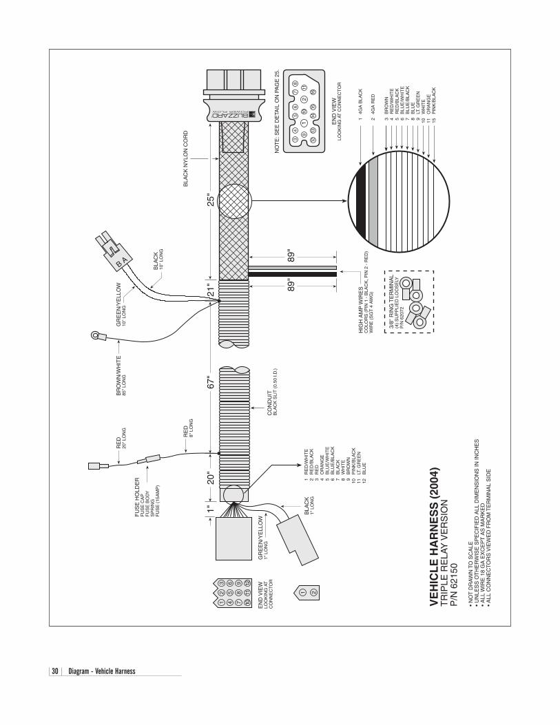
30 Diagram - Vehicle Harness
VE
HIC
LE
HA
RN
ES
S (
2004
)T
RIP
LE R
ELA
Y V
ER
SIO
NP
/N 6
2150
• N
OT
DR
AW
N T
O S
CA
LE•
UN
LES
S O
TH
ER
WIS
E S
PE
CIF
IED
ALL
DIM
EN
SIO
NS
IN IN
CH
ES
•A
LL W
IRE
18
GA
EX
CE
PT
AS
MA
RK
ED
• A
LL C
ON
NE
CTO
RS
VIE
WE
D F
RO
M T
ER
MIN
AL
SID
E
34
9
13
12
56
78
1110
1415
1612
EN
D V
IEW
LOO
KIN
G A
T C
ON
NE
CT
OR
NO
TE
: SE
E D
ETA
IL O
N P
AG
E 2
5.
25"
21"
67"
89"
89"
14G
A B
LAC
K
24G
A R
ED
3B
RO
WN
4R
ED
/WH
ITE
5R
ED
/BLA
CK
6B
LUE
/WH
ITE
7B
LUE
/BLA
CK
8B
LUE
9LT
. GR
EE
N10
WH
ITE
11O
RA
NG
E15
P
INK
/BLA
CK
HIG
H A
MP
WIR
ES
CO
LOR
S (
PIN
1 -
BLA
CK
, PIN
2 -
RE
D)
WIR
E (
SG
T 4
AW
G)
CO
ND
UIT
BLA
CK
SLI
T (
0.50
I.D
.)
BR
OW
N/W
HIT
E85
" LO
NG
RE
D8"
LO
NG
RE
D20
" LO
NG
20"
1"
FU
SE
HO
LDE
RF
US
E C
AP
FU
SE
BO
DY
SP
RIN
GF
US
E (
15A
MP
)
EN
D V
IEW
LOO
KIN
G A
TC
ON
NE
CTO
R
12
3
45
6
78
9
1011
12
1 2
GR
EE
N/Y
ELL
OW
1" L
ON
G
BLA
CK
1" L
ON
G1
RE
D/W
HIT
E2
RE
D/B
LAC
K3
RE
D4
OR
AN
GE
5B
LUE
/WH
ITE
6B
LUE
/BLA
CK
7B
LAC
K8
WH
ITE
9B
RO
WN
10P
INK
/BLA
CK
11LT
. GR
EE
N12
B
LUE
BLA
CK
NY
LON
CO
RD
3/8"
RIN
G T
ER
MIN
AL
(4)
SU
PP
LIE
D L
OO
SE
LYP
/N 6
2072
GR
EE
N/Y
ELL
OW
10"
LON
G
BLA
CK
10"
LON
G
BA
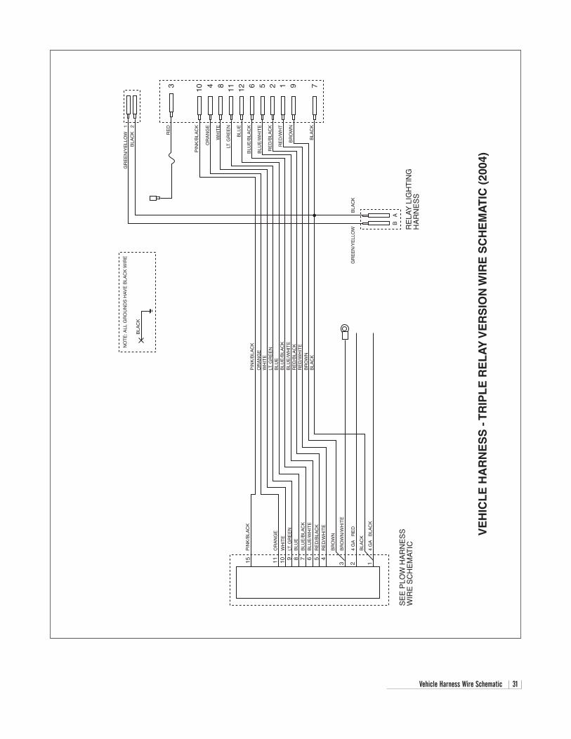
Vehicle Harness Wire Schematic 31
VE
HIC
LE
HA
RN
ES
S -
TR
IPL
E R
EL
AY
VE
RS
ION
WIR
E S
CH
EM
AT
IC (
2004
)
GR
EE
N/Y
ELL
OW
1
BLA
CK
2
3 10 4 8 11 12 6 5 2 1 9 7
RE
D
PIN
K/B
LAC
K
OR
AN
GE
WH
ITE
LT. G
RE
EN
BLU
E
BLU
E/B
LAC
K
BLU
E/W
HIT
E
RE
D/B
LAC
K
RE
D/W
HT
BR
OW
N
BLA
CK
GR
EE
N/Y
ELL
OW
NO
TE
: ALL
GR
OU
ND
S H
AV
E B
LAC
K W
IRE
BLA
CK
15 11 10 9
PIN
K/B
LAC
K
8 7
OR
AN
GE
PIN
K/B
LAC
K
OR
AN
GE
WH
ITE
LT. G
RE
EN
BLU
E
BLU
E/B
LAC
K6
BLU
E/W
HIT
E
5R
ED
/BLA
CK
4R
ED
/WH
ITE
3
BR
OW
N
BR
OW
N/W
HIT
E
24
GA
R
ED
14
GA
B
LAC
K
BLA
CK
WH
ITE
LT. G
RE
EN
BLU
EB
LUE
/BLA
CK
BLU
E/W
HIT
ER
ED
/BLA
CK
RE
D/W
HIT
EB
RO
WN
BLA
CK
SE
E P
LOW
HA
RN
ES
SW
IRE
SC
HE
MAT
IC
BLA
CK
RE
LAY
LIG
HT
ING
HA
RN
ES
S
BA
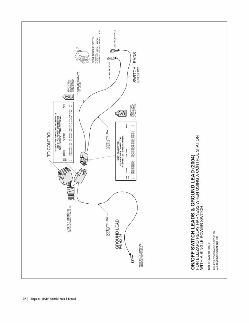
32 Diagram - On/Off Switch Leads & Ground
ON
/OF
F S
WIT
CH
LE
AD
S &
GR
OU
ND
LE
AD
(20
04)
FO
R B
LIZ
ZA
RD
RE
LAY
HA
RN
ES
S W
HE
N U
SIN
G A
CO
NT
RO
L S
TAT
ION
WIT
H A
SIN
GLE
PO
WE
R S
WIT
CH
NO
T D
RA
WN
TO
SC
ALE
UN
LES
S O
TH
ER
WIS
E S
PE
CIF
IED
ALL
DIM
EN
SIO
NS
IN IN
CH
ES
TO C
ON
TR
OL
“AM
P”
CO
NN
EC
TOR
(2)
PIN
PO
WE
R C
ON
NE
CTO
RW
ITH
“M
OL
EX
” M
AL
E T
ER
MIN
AL
PIN
C
OL
OR
FU
NC
TIO
NA
WG
NO
.
1G
RE
EN
/YE
LLO
WR
ELA
Y G
RO
UN
D (
FR
OM
SW
ITC
H)
182
GR
EE
N/Y
ELL
OW
RE
LAY
GR
OU
ND
(F
RO
M S
WIT
CH
)18
EN
D V
IEW
LOO
KIN
G A
TC
ON
NE
CTO
R
1 2
“MO
LE
X”
FR
EE
HA
NG
ING
RE
CE
PTA
CL
E.0
93 (
2) P
IN P
OW
ER
CO
NN
EC
TOR
WIT
H “
MO
LE
X”
FE
MA
LE
TE
RM
INA
L
PIN
C
OL
OR
FU
NC
TIO
NA
WG
NO
.
1G
RE
EN
/YE
LLO
WR
ELA
Y G
RO
UN
D (
FR
OM
VE
H. H
AR
NE
SS
)18
2G
RE
EN
/YE
LLO
WR
ELA
Y G
RO
UN
D (
FR
OM
#10
RIN
G T
ER
M.)
18
1 2E
ND
VIE
WLO
OK
ING
AT
CO
NN
EC
TOR
GR
EE
N/Y
ELL
OW
12"
LON
G
GR
EE
N/Y
ELL
OW
12"
LON
G.2
50 R
EC
EP
TAC
LE
.250
RE
CE
PTA
CLE
SW
ITC
H L
EA
DS
P/N
621
27
GR
OU
ND
LE
AD
P/N
621
26GR
EE
N/Y
ELL
OW
24"
LON
G
#10
RIN
G T
ER
MIN
AL
GR
OU
ND
TO
VE
HIC
LE
VE
HIC
LE H
AR
NE
SS
SE
E D
IAG
RA
M O
N P
AG
E 3
0.
DP
DT
TO
GG
LE S
WIT
CH
P/N
620
24N
OT
E: S
EE
INS
TALL
ATIO
NIN
ST
RU
CT
ION
S O
N P
AG
ES
11
& 1
2.
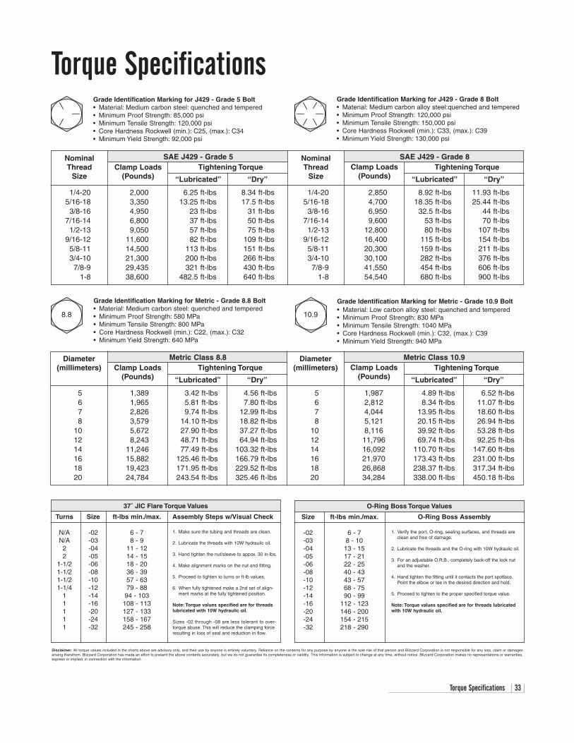
Torque Specifications 33
1. Make sure the tubing and threads are clean.
2. Lubricate the threads with 10W hydraulic oil.
3. Hand tighten the nut/sleeve to appox. 30 in-lbs.
4. Make alignment marks on the nut and fitting.
5. Proceed to tighten to turns or ft-lb values.
6. When fully tightened make a 2nd set of align-ment marks at the fully tightened position.
Note: Torque values specified are for threadslubricated with 10W hydraulic oil.
Sizes -02 through -08 are less tolerant to over-torque abuse. This will reduce the clamping forceresulting in loss of seal and reduction in flow.
37˚ JIC Flare Torque Values
Turns Size ft-lbs min./max. Assembly Steps w/Visual Check
N/A -02 6 - 7N/A -03 8 - 92 -04 11 - 122 -05 14 - 15
1-1/2 -06 18 - 201-1/2 -08 36 - 391-1/2 -10 57 - 631-1/4 -12 79 - 88
1 -14 94 - 1031 -16 108 - 1131 -20 127 - 1331 -24 158 - 1671 -32 245 - 258
Metric Class 8.8 Metric Class 10.9Tightening Torque Tightening Torque
“Lubricated” “Dry” “Lubricated” “Dry”
5 1,389 3.42 ft-lbs 4.56 ft-lbs 5 1,987 4.89 ft-lbs 6.52 ft-lbs6 1,965 5.81 ft-lbs 7.80 ft-lbs 6 2,812 8.34 ft-lbs 11.07 ft-lbs7 2,826 9.74 ft-lbs 12.99 ft-lbs 7 4,044 13.95 ft-lbs 18.60 ft-lbs8 3,579 14.10 ft-lbs 18.82 ft-lbs 8 5,121 20.15 ft-lbs 26.94 ft-lbs
10 5,672 27.90 ft-lbs 37.27 ft-lbs 10 8,116 39.92 ft-lbs 53.28 ft-lbs12 8,243 48.71 ft-lbs 64.94 ft-lbs 12 11,796 69.74 ft-lbs 92.25 ft-lbs14 11,246 77.49 ft-lbs 103.32 ft-lbs 14 16,092 110.70 ft-lbs 147.60 ft-lbs16 15,882 125.46 ft-lbs 166.79 ft-lbs 16 21,970 173.43 ft-lbs 231.00 ft-lbs18 19,423 171.95 ft-lbs 229.52 ft-lbs 18 26,868 238.37 ft-lbs 317.34 ft-lbs20 24,784 243.54 ft-lbs 325.46 ft-lbs 20 34,284 338.00 ft-lbs 450.18 ft-lbs
Torque Specifications
SAE J429 - Grade 5 SAE J429 - Grade 8Tightening Torque Tightening Torque
“Lubricated” “Dry” “Lubricated” “Dry”
1/4-20 2,000 6.25 ft-lbs 8.34 ft-lbs 1/4-20 2,850 8.92 ft-lbs 11.93 ft-lbs5/16-18 3,350 13.25 ft-lbs 17.5 ft-lbs 5/16-18 4,700 18.35 ft-lbs 25.44 ft-lbs3/8-16 4,950 23 ft-lbs 31 ft-lbs 3/8-16 6,950 32.5 ft-lbs 44 ft-lbs
7/16-14 6,800 37 ft-lbs 50 ft-lbs 7/16-14 9,600 53 ft-lbs 70 ft-lbs1/2-13 9,050 57 ft-lbs 75 ft-lbs 1/2-13 12,800 80 ft-lbs 107 ft-lbs
9/16-12 11,600 82 ft-lbs 109 ft-lbs 9/16-12 16,400 115 ft-lbs 154 ft-lbs5/8-11 14,500 113 ft-lbs 151 ft-lbs 5/8-11 20,300 159 ft-lbs 211 ft-lbs3/4-10 21,300 200 ft-lbs 266 ft-lbs 3/4-10 30,100 282 ft-lbs 376 ft-lbs7/8-9 29,435 321 ft-lbs 430 ft-lbs 7/8-9 41,550 454 ft-lbs 606 ft-lbs
1-8 38,600 482.5 ft-lbs 640 ft-lbs 1-8 54,540 680 ft-lbs 900 ft-lbs
Clamp Loads(Pounds)
Clamp Loads(Pounds)
NominalThread
Size
NominalThread
Size
Grade Identification Marking for J429 - Grade 5 Bolt• Material: Medium carbon steel: quenched and tempered• Minimum Proof Strength: 85,000 psi• Minimum Tensile Strength: 120,000 psi• Core Hardness Rockwell (min.): C25, (max.): C34• Minimum Yield Strength: 92,000 psi
Grade Identification Marking for J429 - Grade 8 Bolt• Material: Medium carbon alloy steel:quenched and tempered• Minimum Proof Strength: 120,000 psi• Minimum Tensile Strength: 150,000 psi• Core Hardness Rockwell (min.): C33, (max.): C39• Minimum Yield Strength: 130,000 psi
8.8
Clamp Loads(Pounds)
Clamp Loads(Pounds)
Diameter(millimeters)
Diameter(millimeters)
Grade Identification Marking for Metric - Grade 8.8 Bolt• Material: Medium carbon steel: quenched and tempered• Minimum Proof Strength: 580 MPa• Minimum Tensile Strength: 800 MPa• Core Hardness Rockwell (min.): C22, (max.): C32 • Minimum Yield Strength: 640 MPa
10.9
Grade Identification Marking for Metric - Grade 10.9 Bolt• Material: Low carbon alloy steel: quenched and tempered• Minimum Proof Strength: 830 MPa• Minimum Tensile Strength: 1040 MPa• Core Hardness Rockwell (min.): C32, (max.): C39• Minimum Yield Strength: 940 MPa
O-Ring Boss Torque Values
Size ft-lbs min./max. O-Ring Boss Assembly
-02 6 - 7-03 8 - 10-04 13 - 15-05 17 - 21-06 22 - 25-08 40 - 43-10 43 - 57-12 68 - 75-14 90 - 99-16 112 - 123-20 146 - 200-24 154 - 215-32 218 - 290
1. Verify the port, O-ring, sealing surfaces, and threads areclean and free of damage.
2. Lubricate the threads and the O-ring with 10W hydraulic oil.
3. For an adjustable O.R.B., completely back-off the lock nutand the washer.
4. Hand tighten the fitting until it contacts the port spotface.Point the elbow or tee in the desired direction and hold.
5. Proceed to tighten to the proper specified torque value.
Note: Torque values specified are for threads lubricatedwith 10W hydraulic oil.
Disclaimer: All torque values included in the charts above are advisory only, and their use by anyone is entirely voluntary. Reliance on the contents for any purpose by anyone is the sole risk of that person and Blizzard Corporation is not responsible for any loss, claim or damagesarising therefrom. Blizzard Corporation has made an effort to present the above contents accurately, but we do not guarantee its completeness or validity. This information is subject to change at any time, without notice. Blizzard Corporation makes no representations or warranties,express or implied, in connection with the information.

34 Troubleshooting Guide (1 of 2)
Problem Probable Cause(s) Suggested Remedy
Pump will not run. Plow wire harness may not be properly connected to the Verify the wire harnesses are properly connected.vehicle wire harness. Review the instruction on pages 9-12.
Power or ground cables to the battery, pump or solenoid Properly connect all cables. Clean and lubricate withmay not be properly connected. dielectric grease. If power does not resume, check the
continuity of all cables to find the break.
Pump will not run, power to the solenoid. The black ground wire and brown/white activation wire on Properly connect both cables. Test for power by initiat- the solenoid are not properly connected. ing any joystick function except the float. Note: The
POWER rocker switch must be in the “ON” position toproperly test any plow function. If the solenoid isgrounded and no power exists, diagnose the plow &truck wire harnesses.
Pump will not run with power to the solenoid. The red, hot wire to the pump motor is not properly Connect red wire and check the black ground wire. If Brown/white activation wire and ground are connected. problem is not resolved, the solenoid could be inoper-properly connected. able or the pump motor may be worn. Replace the
solenoid if there is no power to the pump. Replace the pump motor if it is receiving power.
Pump will not turn off. Do not allow the pump Solenoid may be damaged. Disconnect the brown/white activation wire from themotor to continuously run. Unplug both of the solenoid. If the problem is not resolved, replace theharnesses until the pump can be tested or a solenoid.Blizzard Dealer can diagnose the problem.
Short in the joystick control or wire harness. Disconnect the joystick in the cab. If the solenoid turnsoff, there is a short in the electrical system.
Pump runs but plow functions are slow. Fluid level in the pump reservoir is low. Fluid is leaking. Add fluid to within 3/4” from the top of the tank. Check for leaks around the pump, manifold and cylinders.
System pressure may be set too low. Increasing the Adjust the pressure. Remove the hex cap on top of the pressure excessively will increase the amperage draw. pump and turn the screw clockwise. Proper systemThis could damage the vehicle wire harness. pressure should be set at 2400 PSI. Test functions and
repeat procedure as needed.
Amperage from the vehicle’s alternator is too low. Repair or replace vehicle alternator. System amperage draw is 150 Amps at 1500 PSI.
Pump filter may be clogged. Remove the pump tank and thoroughly clean the filter.
A-frame latch will not move. Draw latch is binding the A-frame latch. Lower the draw latch to relieve binding on the A-frame latch and reposition the A-frame latch as needed.
Plow will not lift. Pump works properly. Control station in the cab may not be properly connected. Connect the power connector from the control to thevehicle wire harness.
A-frame latch is in the (down) locked position. Lift the A-frame latch into the raised position.
Diode loop harness may be corroded or could have failed. Clean diode loop harness thoroughly and/or replace.
Troubleshooting GuidePrior to diagnosing your straight blade, verify that all connectors (plow and vehicle wire harness plugs, headlight adapters,control box, fused hot lead, draw latch switch, solenoid ground wire connection, coil wire lead harness, plow headlightharnesses) are free of corrosion and are well lubricated with dielectric grease. Insuring that all connectors are in goodworking order will save time in determining your snowplow’s service needs.
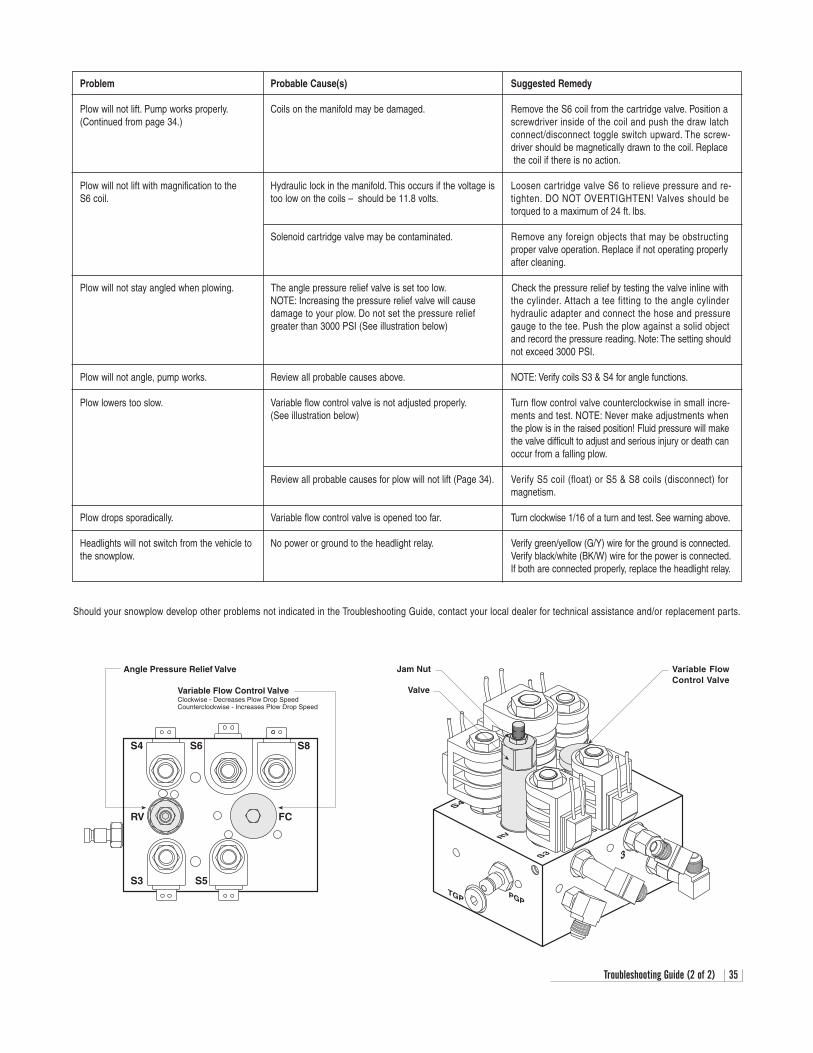
Troubleshooting Guide (2 of 2) 35
Valve
Jam Nut Variable FlowControl Valve
Angle Pressure Relief Valve
Variable Flow Control ValveClockwise - Decreases Plow Drop SpeedCounterclockwise - Increases Plow Drop Speed
Problem Probable Cause(s) Suggested Remedy
Plow will not lift. Pump works properly. Coils on the manifold may be damaged. Remove the S6 coil from the cartridge valve. Position a(Continued from page 34.) screwdriver inside of the coil and push the draw latch
connect/disconnect toggle switch upward. The screw-driver should be magnetically drawn to the coil. Replace the coil if there is no action.
Plow will not lift with magnification to the Hydraulic lock in the manifold. This occurs if the voltage is Loosen cartridge valve S6 to relieve pressure and re-S6 coil. too low on the coils – should be 11.8 volts. tighten. DO NOT OVERTIGHTEN! Valves should be
torqued to a maximum of 24 ft. lbs.
Solenoid cartridge valve may be contaminated. Remove any foreign objects that may be obstructingproper valve operation. Replace if not operating properlyafter cleaning.
Plow will not stay angled when plowing. The angle pressure relief valve is set too low. Check the pressure relief by testing the valve inline with NOTE: Increasing the pressure relief valve will cause the cylinder. Attach a tee fitting to the angle cylinderdamage to your plow. Do not set the pressure relief hydraulic adapter and connect the hose and pressuregreater than 3000 PSI (See illustration below) gauge to the tee. Push the plow against a solid object
and record the pressure reading. Note: The setting shouldnot exceed 3000 PSI.
Plow will not angle, pump works. Review all probable causes above. NOTE: Verify coils S3 & S4 for angle functions.
Plow lowers too slow. Variable flow control valve is not adjusted properly. Turn flow control valve counterclockwise in small incre-(See illustration below) ments and test. NOTE: Never make adjustments when
the plow is in the raised position! Fluid pressure will makethe valve difficult to adjust and serious injury or death canoccur from a falling plow.
Review all probable causes for plow will not lift (Page 34). Verify S5 coil (float) or S5 & S8 coils (disconnect) formagnetism.
Plow drops sporadically. Variable flow control valve is opened too far. Turn clockwise 1/16 of a turn and test. See warning above.
Headlights will not switch from the vehicle to No power or ground to the headlight relay. Verify green/yellow (G/Y) wire for the ground is connected.the snowplow. Verify black/white (BK/W) wire for the power is connected.
If both are connected properly, replace the headlight relay.
Should your snowplow develop other problems not indicated in the Troubleshooting Guide, contact your local dealer for technical assistance and/or replacement parts.

BLIZZARD®
LIMITED CONSUMER WARRANTYThis warranty covers defects in material and workmanship except as set forth below.
WARRANTED PARTY:This warranty applies only to the “Original Purchaser” who purchased this plow from an Authorized Blizzard Dealer,
for personal, family or household use.
TERM OF WARRANTY:This Blizzard straight blade snowplow is warranted for the following period:
Parts and labor are warranted for one year from date of purchase.
BLIZZARD CORPORATION’S WARRANTY REMEDY:Blizzard Corporation will, at its sole discretion, repair or replace defective parts at no charge.
CUSTOMERS RESPONSIBILITY:To obtain warranty service, the purchaser must return the defective snowplow to any Authorized Blizzard Dealer.
The purchaser must verify the original purchase date. Transportation costs to and from the dealer will be the responsibility of the purchaser.
ITEMS NOT COVERED UNDER THIS WARRANTY:This limited warranty does not cover the following:
1. Expendable parts such as cutting edges, plow shoes, hoses, fasteners, blade guides, paint finish, etc.
2. Any snowplow or part thereof which has been repaired or altered by anyone other than an Authorized Blizzard Dealer.
3. Any snowplow or part thereof which has been subject to neglect, misuse, accident, improper installation, maintenance,or storage. This includes, but is not limited to, corrosion of any electrical components.
4. Snowplows mounted on vehicles other than those for whom Blizzard Corporation has provided a specific undercarriage system.
5. Blizzard Corporation does not assume liability for damage to the purchaser's vehicle resulting from the attachmentand use of a Blizzard straight blade snowplow. Vehicle risk is the sole responsibility of the purchaser.
WARRANTY LIMITATIONS:THIS WARRANTY IS OFFERED IN LIEU OF ANY OTHER EXPRESS WARRANTY.
THE DURATION OF ALL IMPLIED WARRANTIES, INCLUDING BUT NOT LIMITED TO THE IMPLIED WARRANTIES OF MERCHANTABILITY AND FITNESS FOR A PARTICULAR PURPOSE, ARE LIMITED
TO THE DURATION OF THIS WARRANTY.
BLIZZARD CORPORATION'S LIABILITY IS EXPRESSLY LIMITED TO REPAIR OR REPLACEMENT OF DEFECTIVE PARTS. BLIZZARD CORPORATION SHALL NOT BE LIABLE FOR CONSEQUENTIAL, INCIDENTALOR CONTINGENT DAMAGES WHATSOEVER, EVEN IF DAMAGES ARE CAUSED BY THE NEGLIGENCE OR
FAULT OF BLIZZARD CORPORATION.
State Laws: Some states do not allow exclusion of incidental or consequential damages or the limitations on howlong an implied warranty lasts, so these limitations or exclusions may not apply to you. This warranty gives you
specific legal rights and you may also have other rights which vary from state to state.
This warranty does not apply if you purchased your snowplow for other than personal, family, or household use. Ifpurchased for other than personal, family or household use, refer to the Blizzard Straight Blade Commercial Warranty.
95 AIRPARK BOULEVARD CALUMET, MICHIGAN 49913 [906] 482-5555
1029-7-99 REV 8/01
COMMERCIAL WARRANTYThis warranty covers defects in material and workmanship except as set forth below.
WARRANTED PARTY:
This warranty applies only to the “Original Purchaser” who purchased this plow from an Authorized Blizzard Dealer,for commercial use.
TERM OF WARRANTY:
This Blizzard straight blade snowplow is warranted for the following period:Parts and labor are warranted for one year from date of purchase.
BLIZZARD CORPORATION’S WARRANTY REMEDY:
Blizzard Corporation will, at its sole discretion, repair or replace defective parts at no charge.
CUSTOMERS RESPONSIBILITY:
To obtain warranty service, the purchaser must return the defective snowplow to any Authorized Blizzard Dealer within thewarranty period. The purchaser must verify the original purchase date. Transportation costs to and from the Dealer will be
the responsibility of the purchaser.
ITEMS NOT COVERED UNDER THIS WARRANTY:
This warranty does not cover the following:
1. Expendable parts such as cutting edges, plow shoes, hoses, fasteners, blade guides, paint finish, etc.
2. Any snowplow or part thereof which has been repaired or altered by anyone other than an Authorized Blizzard Dealer.
3. Any snowplow or part thereof which has been subject to neglect, misuse, accident, improper installation, maintenance,or storage. This includes, but is not limited to, corrosion of any electrical components.
4. Snowplows mounted on vehicles other than those for whom Blizzard Corporation has provided a specific undercarriagesystem.
5. Blizzard Corporation does not assume liability for damage to the purchaser's vehicle resulting from the attachment anduse of a Blizzard straight blade snowplow. Vehicle risk is the sole responsibility of the purchaser.
LIMITS OF BLIZZARD CORPORATION’S LIABILITIES:
BLIZZARD CORPORATION'S LIABILITY IS EXPRESSLY LIMITED TO REPAIR OR REPLACEMENT OF DEFECTIVE PARTS. BLIZZARD CORPORATION SHALL NOT BE LIABLE FOR CONSEQUENTIAL, INCIDENTAL OR CONTINGENT DAMAGES WHATSOEVER, EVEN IF DAMAGES ARE CAUSED BY THE NEGLIGENCE OR
FAULT OF BLIZZARD CORPORATION.
THE FOREGOING WARRANTIES ARE EXCLUSIVE AND IN LIEU OF ALL OTHER EXPRESSED AND IMPLIED WARRANTIES INCLUDING, BUT NOT LIMITED TO, THE IMPLIED WARRANTIES OF MERCHANTABILITY AND
FITNESS FOR A PARTICULAR PURPOSE.
This warranty does not apply if you purchased your snowplow for personal, family, or household use.In this case, refer to the Blizzard Straight Blade Limited Consumer Warranty.
BLIZZARD®
95 AIRPARK BOULEVARD CALUMET, MICHIGAN 49913 [906] 482-5555
1030-7-99 REV 8/01

95 Airpark BoulevardCalumet,MI 49913[888] 680-8600[906] 482-5555[906] 482-5445 Faxwww.blizzardplows.com
Blizzard, Power Hitch and Seat Cinch are trademarks of Blizzard Corporation. Blizzard is registeredin the United States Patent and Trademark Office. Loctite and 242 are registered trademarks of LoctiteCorporation, USA. Velcro is a registered trademark of Velcro Industries B.V. All other trademarks andregistered trademarks are the property of their respective owners. All Blizzard snowplows are protectedby one or more of the following United States Patents: 5,638,618; 5,899,007; 6,178,669; 6,276,076;6,393,737 and 6,615,513. Other patents pending. Copyright © 2004 Blizzard Corporation. All rightsreserved. Made and printed in the USA.1376-04-04