Embed Size (px)
Citation preview
1
The Multiple-Camera 3D Production StudioJonathan Starck*, Atsuto Maki, Shohei Nobuhara, Adrian Hilton, Takashi Matsuyama
Abstract
Multiple-camera systems are currently in development as a means to capture and synthesise highly
realistic three-dimensional (3D) video content. Studio systems for 3D production of human performance
are reviewed from the literature and the practical experience gained in developing prototype studios
is reported across two research laboratories. System design should consider the studio backdrop for
foreground matting, lighting for ambient illumination, the camera configuration for scene capture as well
as accurate geometric and photometric camera calibration.A ground truth evaluation is performed to
quantify the effect of different constraints on the multiple camera system in terms of geometric accuracy
and the requirement for high quality view synthesis. Cameraheight has only a limited influence on surface
visibility, multiple camera sets or an active vision systemcan be required for wide area capture, accurate
reconstruction requires a camera baseline of 25 degrees andthe achievable accuracy is 5-10mm at current
camera resolutions. Accuracy is inherently limited and view dependent rendering is required for view
synthesis with sub-pixel accuracy where display resolutions match camera resolutions. The two prototype
studios are contrasted and state-of-the-art techniques for 3D content production are demonstrated.
I. INTRODUCTION
Since the pioneering work of Kanade et al. [1] introduced thecapture of a 3D Virtualized Reality from
multiple view video, there has been extensive research on the 3D reconstruction and rendering of people
from video images. People form a central element of media content and multiple camera acquisition of a
performance provides interactive control of a virtual viewpoint to create 3D video, termedfree-viewpoint
video. Marker-based camera capture is already widely used in production for feature films and computer
games through either optical or electromagnetic marker systems. This technology allows the motion of
an actor to be replayed on a computer generated character butis inherently limited to the acquisition of
J. Starck and A. Hilton{j.starck, [email protected]} are with the Centre for Vision, Speech and Signal Processing,
University of Surrey, UK. Tel: +44-1483-686030 Fax: +44-1483-686031
A. Maki, S. Nobuhara and T. Matsuyama{maki, nob, [email protected]} are with the Graduate School of Informatics,
Kyoto University, Japan. Tel: +81-75-753-4891 Fax: +81-75-753-4769
August 1, 2008 DRAFT
2
a sparse set of 3D marker points and does not provide detailedinformation on body or cloth movement
or appearance. Markerless performance capture, a virtualisation of reality, provides the detail of a live
performance through 3D video production.
Research to-date has focused on studio-based multiple camera acquisition systems and the computer
vision algorithms required to achieve robust reconstruction and high-quality view synthesis either as
a real-time or off-line post-process. Studios have been developed using different designs in terms of
physical layout, backdrop, lighting, camera system and thechoice of algorithms used for 3D reconstruction
and view synthesis. This paper brings together the experience of two research laboratories developing
prototype multiple-camera systems for 3D production. At the University of Surrey in the UK a free-
viewpoint video system [2] has been developed to create highly realistic animated 3D digital characters.
At Kyoto University in Japan, a free-viewpoint video system[3] has been developed to capture the shape,
appearance and motion of intangible cultural assets for storage, transmission and 3D display.
Three contributions are made in this paper.
• Practical design considerations are identified for a multiple camera capture system.
• A ground-truth evaluation is presented to provide an insight into different design decisions.
• A comparison is provided for 3D production of human performances in two real studios.
Section II describes related work and provides an overview of systems designed to capture the whole-
body shape and appearance of people. Practical issues in designing a multiple camera capture studio
are then presented in Section III. A ground-truth evaluation is presented in Section IV using a synthetic
data-set to assess the effect of geometric accuracy on the camera system design. A practical comparison
is then presented in Section V for two different studios currently in use for human performance capture
and 3D video production. Finally, Section VI draws conclusions on the design and quality of media
production in the multiple camera 3D Production Studio.
II. RELATED WORK
Studio-based multiple-view capture of 3D events has been researched in both computer vision and
computer graphics. In computer vision, markerless human motion tracking and image-based shape recon-
struction have been investigated. In computer graphics, model building is performed for both static and
dynamic shapes, and image-based rendering has been investigated for view synthesis. Recent advances
have seen the convergence of computer vision and computer graphics techniques, which has achieved
offline production of free-viewpoint video with a visual quality comparable to the captured video. In
August 1, 2008 DRAFT
3
this section we summarise the related work in which multiplecamera studio technology is used for 3D
capture and rendering.
A. Model-based shape capture
Markerless human motion capture from single and multiple view video has been a central topic in
computer vision research over the past decade with over 500 papers published in this field in the past
five years alone [4]. Markerless tracking has been combined with shape reconstruction to capture the
changing shape, appearance and motion of a parameterised model from multiple view video. Starck and
Hilton [5] describe a shape optimisation process to match anarticulated surface mesh to multiple shape
cues across camera images. Carranza et al. [6] track a generic humanoid model and adapt the shape to
match multiple silhouette images. Theobalt et al. [7] use the model geometry as an efficient means to
encode multiple view images for transmission and 3D display. Sand et al. [8] capture the shape of the
human body under articulation using multiple silhouette images. Balan et al. [9] derive a parametric model
of shape and pose-dependent deformations from a database ofrange scans of human bodies to match
human shape and pose in multiple views. Model-based techniques introduce prior knowledge to constrain
3D geometric reconstruction in the presence of ambiguitiesand also provide a single consistent model
structure that would allow the analysis of shape deformations for example in coding and transmission or
re-use in animation. However, model-based techniques are inherently limited to a transformation of the
predefined model and cannot be applied to complex scenes withlarge changes in structure such as loose
clothing or hair on the human body.
B. Image-based scene Reconstruction
Image-based 3D scene reconstruction without a prior model is a key problem in computer vision.
Seitz et al. [10] provide a quantitative evaluation of state-of-the-art techniques using multiple camera
views. Conventional stereo-based techniques reconstructa 2.5D depth image representation from two or
more cameras through a regularized search for image correspondence. Stereo reconstruction suffers from
ambiguities in 2D image matching with uniform surface appearance, depth discontinuities and unknown
surface visibility. Volumetric reconstruction techniques instead derive the 3D volume that is consistent
with multiple images. A volume representation allows inference of visibility and integration of appearance
across multiple widely spaced camera views. Shape-from-silhouette (SFS) techniques derive thevisual-
hull, the maximal volume that is consistent with a set of foreground images [11]. However, the visual-hull
only provides an upper bound on the volume of the scene, concavities that are occluded in silhouettes
August 1, 2008 DRAFT
4
are not reconstructed, appearance is not matched across images and phantom volumes can occur that are
consistent with the image silhouettes. Space-carving techniques [12] provide thephoto-hull, the maximal
volume that is photo-consistent across all visible camera images. Independent voxel carving however
suffers either from under or over carving according to the photo-consistency criteria. Regularisation has
been introduced using a level-set approach to multiple viewstereo [13], [14]. Multiple shape cues have
been combined for robust reconstruction using iterative local-surface optimization techniques. The visual-
hull [3], [15], [16], [17] is often used to provide an initialsurface, however optimization is subject to
local minima and the surface is constrained to represent only those structures that are initially defined
and can retain incorrect structures.
C. Video-based Rendering
Image-based rendering is the process of synthesising novelviews from camera images. With no
geometric scene information, synthesis is performed directly by resampling multiple view images as a set
of samples from the light-field in a scene [18]. Highly realistic view synthesis can be achieved at the cost of
requiring dense image sampling to avoid artefacts in interpolating images without exact image registration.
Image-based modelling and image-based rendering have beencombined [19], [20] to synthesize novel
views from a sparse set of cameras by using scene geometry to provide the correspondence between
images. The advantage of view-dependent rendering is that it can overcome inaccuracies in geometric
scene reconstruction by reproducing the change in surface appearance that is sampled in the original
camera images. However, with inexact geometry and errors incamera calibration the correspondence
between camera images can be inexact leading to blurring anddouble exposure effects [16]. Zitnick et
al. [21] demonstrate view synthesis approaching the quality of the original camera images using stereo
reconstruction to provide the underlying scene geometry with a narrow camera baseline.
D. Studio Capture Systems
Camera systems developed for human shape reconstruction and video-based rendering can be charac-
terised by the nature of the reconstruction and rendering process together with the target application area.
Online systems are based on fast and robust shape reconstruction for real-time shape and appearance in
mixed reality environments. Video-rate reconstruction from silhouettes has been achieved using volumetric
discretization [22], [24], [25] and polyhedral intersection [23], [26]. Waschbusch et al. [33] present a
video-rate structured-light system to actively acquire geometry in cluttered scenes. Offline systems have
the potential for more accurate geometric scene reconstruction. Carranza et al. [6], [27] and Sand et al.
August 1, 2008 DRAFT
5
Technique Ref Cameras Coverage Background Reconstruction Applications
Real-time
[22] 5, QVGA, 24bpp, 30fps 360 ◦ Semi-controlled Silhouettes, 15Hz Visualisation
[23] 4, QVGA, 15fps 180 ◦ Semi-controlled Silhouette, 15Hz Visualisation
[24] 6, PAL, 24bpp, 25fps 180◦ Retro-reflective Silhouette, 15Hz On-set Preview
[25] 4, VGA, 16bpp, 30fps 180◦ Semi-controlled Silhouette, 30Hz Virtual Worlds
[26] 6, SVGA, 16bpp, 30fps 360 ◦ Semi-controlled Silhouette, 30Hz Mixed reality
Model-Based
[27] 8, VGA, 16bpp, 30fps 360◦ Semi-controlled Silhouette 3D Video
[8] 3, NTSC, 30fps, 10 mocap 180◦ White Silhouette Modelling
[5] 9, PAL, 25fps 360◦ Blue Silhouette + Stereo Modelling
Model-Free
[28] 51, NTSC, 16bpp, 30fps 360◦ Semi-controlled Stereo Virtualized Reality
[3] 25, VGA, 16bpp, 30fps 360◦ Grey Silhouette + Stereo 3D Video
[29] 8, VGA, 24bpp, 30fps 360◦ Beige Silhouette + Stereo Modelling
[2] 8, HD(1080p), 16bpp, 25fps 360◦ Blue Silhouette + Stereo Animation
Short-baseline
[30] 48, QVGA, 15-20fps 30◦ Natural Colour Mobile cameras
[21] 8, XVGA, 8bpp, 15fps 35◦ Natural Stereo View-Interpolation
[31] 16, 1300x1030, 12fps, 8bpp 30◦ Natural none 3D TV
[32] 100, 1392x1040, 30fps, 8bpp 30◦+ Natural none 3D TV
TABLE I
MULTIPLE CAMERA CAPTURE SYSTEMS
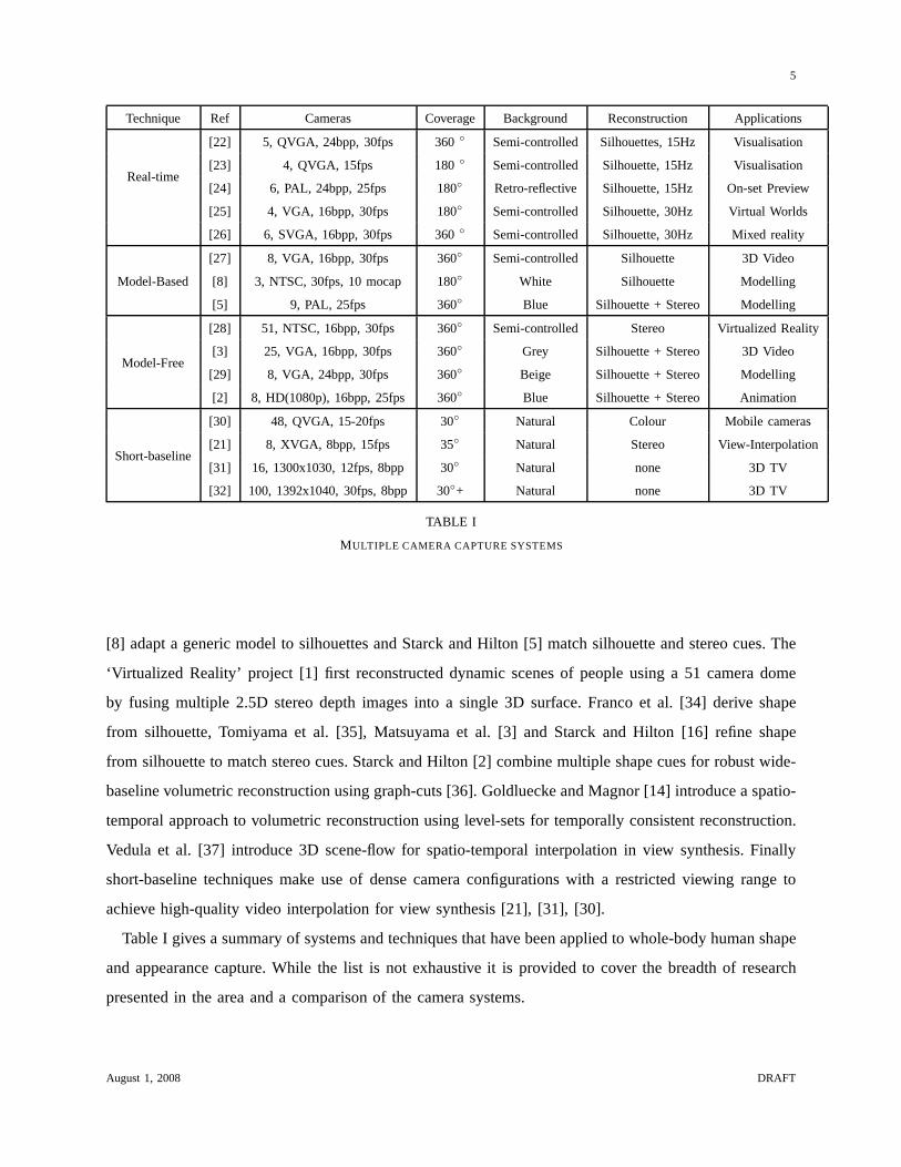
[8] adapt a generic model to silhouettes and Starck and Hilton [5] match silhouette and stereo cues. The
‘Virtualized Reality’ project [1] first reconstructed dynamic scenes of people using a 51 camera dome
by fusing multiple 2.5D stereo depth images into a single 3D surface. Franco et al. [34] derive shape
from silhouette, Tomiyama et al. [35], Matsuyama et al. [3] and Starck and Hilton [16] refine shape
from silhouette to match stereo cues. Starck and Hilton [2] combine multiple shape cues for robust wide-
baseline volumetric reconstruction using graph-cuts [36]. Goldluecke and Magnor [14] introduce a spatio-
temporal approach to volumetric reconstruction using level-sets for temporally consistent reconstruction.
Vedula et al. [37] introduce 3D scene-flow for spatio-temporal interpolation in view synthesis. Finally
short-baseline techniques make use of dense camera configurations with a restricted viewing range to
achieve high-quality video interpolation for view synthesis [21], [31], [30].
Table I gives a summary of systems and techniques that have been applied to whole-body human shape
and appearance capture. While the list is not exhaustive it is provided to cover the breadth of research
presented in the area and a comparison of the camera systems.
August 1, 2008 DRAFT
6
III. STUDIO SYSTEM DESIGN
Designing a multiple camera studio requires a number of decisions to be made in terms of the physical
layout of the studio, the backdrop, illumination, and the camera system for 3D capture. In this section
the factors affecting different design decisions are summarised.
A. Backdrop
Foreground matting [38], the process of extracting the foreground objects from an image, is often
the first step in reconstructing a 3D dynamic scene from multiple view video. Coloured screens allow
relatively simple background removal through a process termedchroma-keyingwhere a known colour or
a narrow range of colours is automatically removed. Blue andgreen are often used as relatively distinct
colours from skin tones. However, a coloured backdrop has several disadvantages. The scene cannot
contain the same colour as the background as it would be removed in matting. The backdrop can also
introduce a mapping of the hue on to to the scene from inter-reflections. Green-screens can prove most
distinct from typical clothing, however green can produce unnatural looking skin where blue is more
complementary to skin tones.
Non-coloured backdrops such as black, white or grey, can be used to avoid constraints on the colour of
the scene. However, a scene can also have a similar appearance to a neutral backdrop. A white background
for example will match white clothing or surface highlightsthat saturate a camera. Self-shadowing will
produce dark regions that may be indistinguishable from a black or grey background. It is also more
difficult to correctly identify shadowed background regions which could feasibly be the same colour
as the scene. Here, a coloured backdrop provides a fixed chroma independent of shading variations to
simplify background identification.
Relatively recently retro-reflective backdrops, such asTruematte, have been developed to provide an
evenly lit coloured background. Screens are made from a fabric that is woven with glass beads to provide
a retroreflective surface. An LED ring is placed around a camera lens to illuminate the fabric and light
is reflected directly back to the camera to give a coloured background. One advantage is that relatively
low light levels can be used to illuminate the backdrop reducing the colour spill onto the foreground,
however the material has a relatively higher cost.
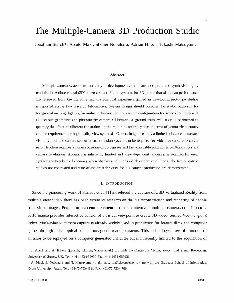
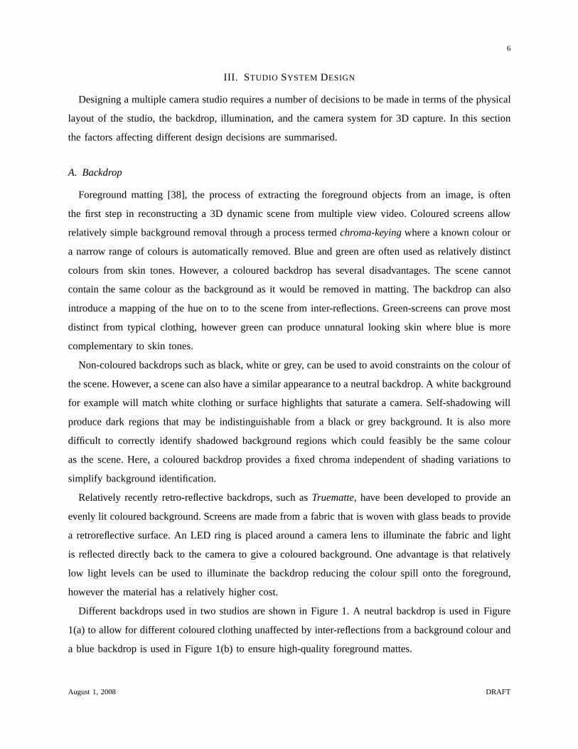
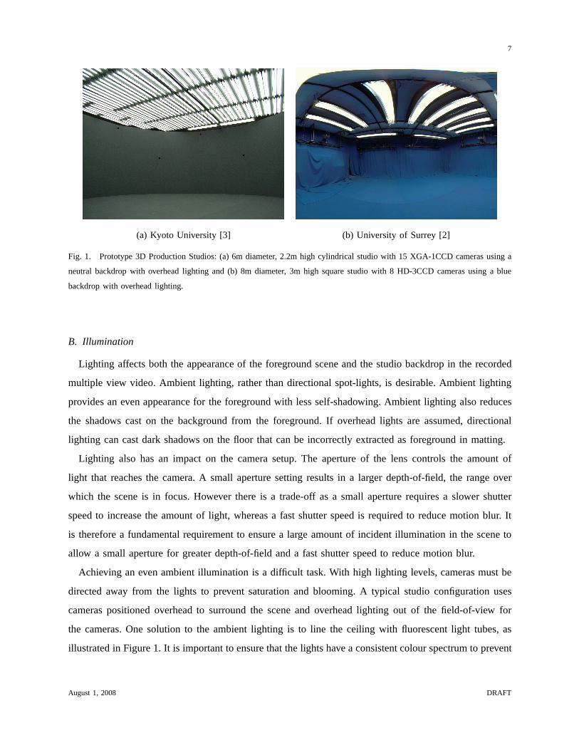
Different backdrops used in two studios are shown in Figure 1. A neutral backdrop is used in Figure
1(a) to allow for different coloured clothing unaffected byinter-reflections from a background colour and
a blue backdrop is used in Figure 1(b) to ensure high-qualityforeground mattes.
August 1, 2008 DRAFT
7
(a) Kyoto University [3] (b) University of Surrey [2]
Fig. 1. Prototype 3D Production Studios: (a) 6m diameter, 2.2m high cylindrical studio with 15 XGA-1CCD cameras using a
neutral backdrop with overhead lighting and (b) 8m diameter, 3m high square studio with 8 HD-3CCD cameras using a blue
backdrop with overhead lighting.
B. Illumination
Lighting affects both the appearance of the foreground scene and the studio backdrop in the recorded
multiple view video. Ambient lighting, rather than directional spot-lights, is desirable. Ambient lighting
provides an even appearance for the foreground with less self-shadowing. Ambient lighting also reduces
the shadows cast on the background from the foreground. If overhead lights are assumed, directional
lighting can cast dark shadows on the floor that can be incorrectly extracted as foreground in matting.
Lighting also has an impact on the camera setup. The apertureof the lens controls the amount of
light that reaches the camera. A small aperture setting results in a larger depth-of-field, the range over
which the scene is in focus. However there is a trade-off as a small aperture requires a slower shutter
speed to increase the amount of light, whereas a fast shutterspeed is required to reduce motion blur. It
is therefore a fundamental requirement to ensure a large amount of incident illumination in the scene to
allow a small aperture for greater depth-of-field and a fast shutter speed to reduce motion blur.
Achieving an even ambient illumination is a difficult task. With high lighting levels, cameras must be
directed away from the lights to prevent saturation and blooming. A typical studio configuration uses
cameras positioned overhead to surround the scene and overhead lighting out of the field-of-view for
the cameras. One solution to the ambient lighting is to line the ceiling with fluorescent light tubes, as
illustrated in Figure 1. It is important to ensure that the lights have a consistent colour spectrum to prevent
August 1, 2008 DRAFT
8
uneven illumination from different areas of the ceiling andflickerless operation is required to ensure that
the lighting level is consistent over a video sequence.
C. Cameras
Making the right choice of camera is crucial in designing a studio. There is a clear trade-off between
the cost of the camera system and the number or resolution of the cameras required. At one end of the
spectrum there is the high-cost camera equipment that wouldbe used in a broadcast or film production
scenario, see for example [2]. These systems use professional 3-CCD cameras and lenses that can typically
capture uncompressed 24bpp colour resolution images to a dedicated capture server per camera. This
high-cost solution can provide high resolution and high colour-depth images but has high-bandwidth
requirements and the cost limits the number of cameras available for a given budget.
Digital machine vision cameras are often used as a relatively low cost solution, see for example
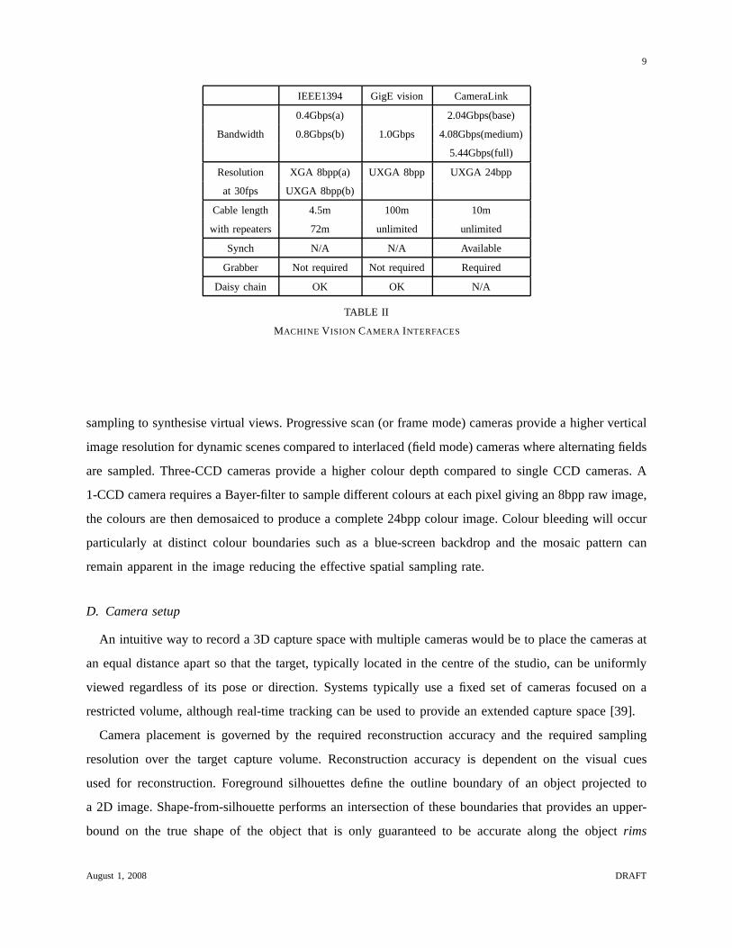
[26]. There are three different types of cameras characterised according to their interfaces, IEEE1394
(FireWire or i.Link), GigE Vision, and CameraLink. The choice of camera is governed by the bandwidth
and resolution as well as for example the cable length that can be used according to the size of the
studio. The characteristic of each interface is summarisedin Table II. It is a critical requirement that
all cameras are synchronised to sample a dynamic scene over the same time period from each camera
viewpoint, prohibiting the use of many consumer grade cameras.
IEEE1394 (FireWire or i.Link) is a serial bus with a data rate of 400Mbps or 800Mbps. This gives a
maximum video resolution of XGA or UXGA/HD for 1CCD 8bpp dataat 30fps. The maximum metal
cable length is 4.5m with extensions provided by repeators.Optic fibre cable is also available with optic-
electronic converters. Since this is a packet-based bus interface external trigger signals cannot be sent,
although some cameras accept a “magic packet” which allows several cameras on different buses to
synchronize. GigE Vision is another specification for a packet-based bus interface which utilizes gigabit
ethernet as the physical layer. This system can transfer data at 1Gbps giving a maximum resolution of
UXGA/HD video at 30fps for 1CCD 8bpp data. The cable length isup to 100m. The CameraLink interface
connects cameras directly to enable real-time control including trigger signals for synchronisation. Data
can be transferred at UXGA resolution for 3CCD video at 30fps. The cable length can be up to 10m
depending on the desired bitrate and optic fibre cables with an optic-electronic converter can be used to
extend the cable length. It is also possible to provide powerto cameras if used with PoCL (power over
CameraLink) cables. High quality video images are requiredboth to simplify tasks such as foreground
matting and image matching for geometric scene reconstruction, as well as to provide the highest surface
August 1, 2008 DRAFT
9
IEEE1394 GigE vision CameraLink
Bandwidth
0.4Gbps(a)
1.0Gbps
2.04Gbps(base)
0.8Gbps(b) 4.08Gbps(medium)
5.44Gbps(full)
Resolution XGA 8bpp(a) UXGA 8bpp UXGA 24bpp
at 30fps UXGA 8bpp(b)
Cable length 4.5m 100m 10m
with repeaters 72m unlimited unlimited
Synch N/A N/A Available
Grabber Not required Not required Required
Daisy chain OK OK N/A
TABLE II
MACHINE V ISION CAMERA INTERFACES
sampling to synthesise virtual views. Progressive scan (orframe mode) cameras provide a higher vertical
image resolution for dynamic scenes compared to interlaced(field mode) cameras where alternating fields
are sampled. Three-CCD cameras provide a higher colour depth compared to single CCD cameras. A
1-CCD camera requires a Bayer-filter to sample different colours at each pixel giving an 8bpp raw image,
the colours are then demosaiced to produce a complete 24bpp colour image. Colour bleeding will occur
particularly at distinct colour boundaries such as a blue-screen backdrop and the mosaic pattern can
remain apparent in the image reducing the effective spatialsampling rate.
D. Camera setup
An intuitive way to record a 3D capture space with multiple cameras would be to place the cameras at
an equal distance apart so that the target, typically located in the centre of the studio, can be uniformly
viewed regardless of its pose or direction. Systems typically use a fixed set of cameras focused on a
restricted volume, although real-time tracking can be usedto provide an extended capture space [39].
Camera placement is governed by the required reconstruction accuracy and the required sampling
resolution over the target capture volume. Reconstructionaccuracy is dependent on the visual cues
used for reconstruction. Foreground silhouettes define theoutline boundary of an object projected to
a 2D image. Shape-from-silhouette performs an intersection of these boundaries that provides an upper-
bound on the true shape of the object that is only guaranteed to be accurate along the objectrims
August 1, 2008 DRAFT
10
that generate the silhouette images. Reconstruction accuracy is dependent on sampling sufficient rims to
approximate the underlying scene and typically requires a large number of evenly spaced camera views.
Stereo correspondence on the other hand can recover dense surface geometry by matching appearance
between viewpoints. Matching is based on maximising the correlation between corresponding patches
in camera images. At short baselines, appearance will be similar increasing the likelihood that a good
match can be recovered, however the accuracy in recovering depth is reduced as a small error in image
matching can lead to large errors in depth. Conversely with large baselines, appearance will vary between
image patches reducing the chance of a good match, however the reconstruction accuracy is increased
due to a reduced depth ambiguity. Cameras should ideally be placed to maximise the accuracy from these
complementary shape cues in reconstruction.
For a fixed arrangement of cameras the sampling resolution will define both the reconstruction accuracy
that can be achieved and the sampling of surface appearance to synthesise new views. As the surface
sampling rate increases, finer resolution matches will be derived which will reduce the reconstruction
error. Sampling is effectively governed by the resolution of the output image, defined by the number of
sampling elements on the camera and any resampling to construct the output image, as well as camera
zoom, the focal-length of the lens controlling the field-of-view in the scene that is imaged. A higher image
resolution and a restricted field of view will increase the surface sampling rate. However, a restricted
field-of-view will require a greater number of cameras to cover the entire scene.
E. Calibration
Camera calibration is a fundamental step in capturing 3D digital media that directly affects both the
accuracy of 3D shape capture and the quality of visual synthesis. For studio production where cameras
may be reconfigured many times in one day and the recording time for paid performers is critical, simple
and quick methods of calibration are of key practical importance.
Geometric calibration must define the intrinsic (focal length, centre-of-projection, radial distortion)
and extrinsic (pose, orientation) camera parameters. Techniques are characterised by the available input,
namely point correspondences which can be between 2D imagesor between a 2D image and 3D space.
Popular approaches include a 1-step calibration process ora 2-step process. In a 1-step approach, both
the intrinsic and extrinsic parameters are calibrated witha fixed 3D object, using for example Tsai’s
algorithm [40]. A 2-step approach recovers intrinsic parameters first using a known object such as a
planar chart [41] and then derives extrinsics using 2D to 2D point correspondences between images [42].
A clear prerequisite is that points should cover the entire studio to ensure accurate reconstruction for
August 1, 2008 DRAFT
11
the 3D capture volume. Point-based [43] and wand-based [44]techniques provide a flexible method to
calibrate opposing or non-overlapping cameras where a chart for example would not be simultaneously
visible from all camera viewpoints.
Photometric calibration is required to balance the sampledappearance in different cameras. Within a
camera vignetting distortion can occur, where image brightness decreases with distance from the image
centre as a result of shading in the camera lens. In practise compensation for vignetting is not required
unless a wide aperture is used. Differences in appearance will however occur between cameras due to
different colour responses. A simple colour calibration step matches the white-point, together with the
black and white levels for the scene in each camera. The whitepoint defines the relative proportion of
red, green and blue components defining the colour white and the levels serve to match the dynamic
range for the scene. More accurate calibration requires matching of the individual colour response curves
across different cameras, for example by adjusting the offset and gain to match a linear response with
gamma correction switched off, or by calibrating the individual colour response curves [45].
F. Summary
Studio design choices are governed by the type of scenes thatwill be recorded and the state-of-
the-art techniques for a given budget. The backdrop is chosen to give the maximum contrast with a
foreground scene for accurate foreground matting with the minimum impact of the content of the scene.
The maximum amount of consistent ambient illumination is required that can be placed out of view
of the camera acquisition system. Camera calibration should be as accurate as can be achieved using
state-of-the-art techniques. Design decisions are therefore reduced to the physical arrangement and setup
of the multiple camera system for 3D production. The cost forthe choice on the quality and number of
cameras will then in turn influence the design of the lightingand backdrop for a fixed studio budget.
Supply of studio equipment is territory dependent, for example chroma-key backdrop and studio rigging
equipment can be obtained from broadcast suppliers, retro-reflective material (reflecmedia.com), lighting
(cirrolite.com, kino-flo.com), cameras (Sony, ptgrey.com), multi-camera storage (Sony, ioindustries.com,
DVS) and complete capture solutions (fourdviews.jexiste.fr).
IV. GROUND TRUTH EVALUATION
A quantitative evaluation is now presented using a ground-truth synthetic data-set to address design
decisions in a 3D production studio. Experiments are performed to illustrate the effect of geometric
accuracy in answering the following questions: How many cameras are required? Where should cameras
August 1, 2008 DRAFT
12
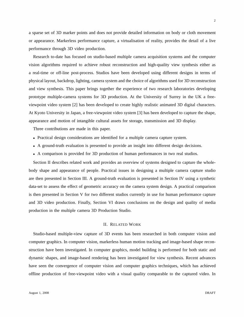
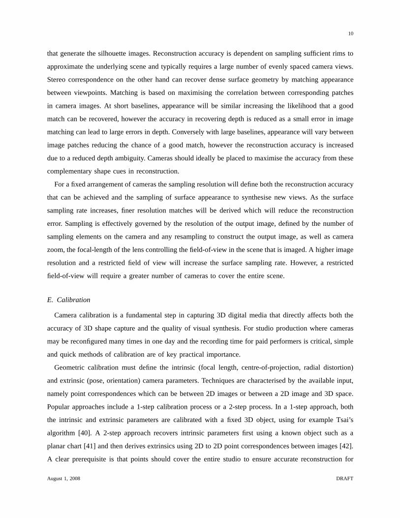
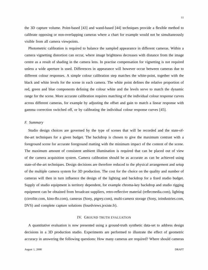
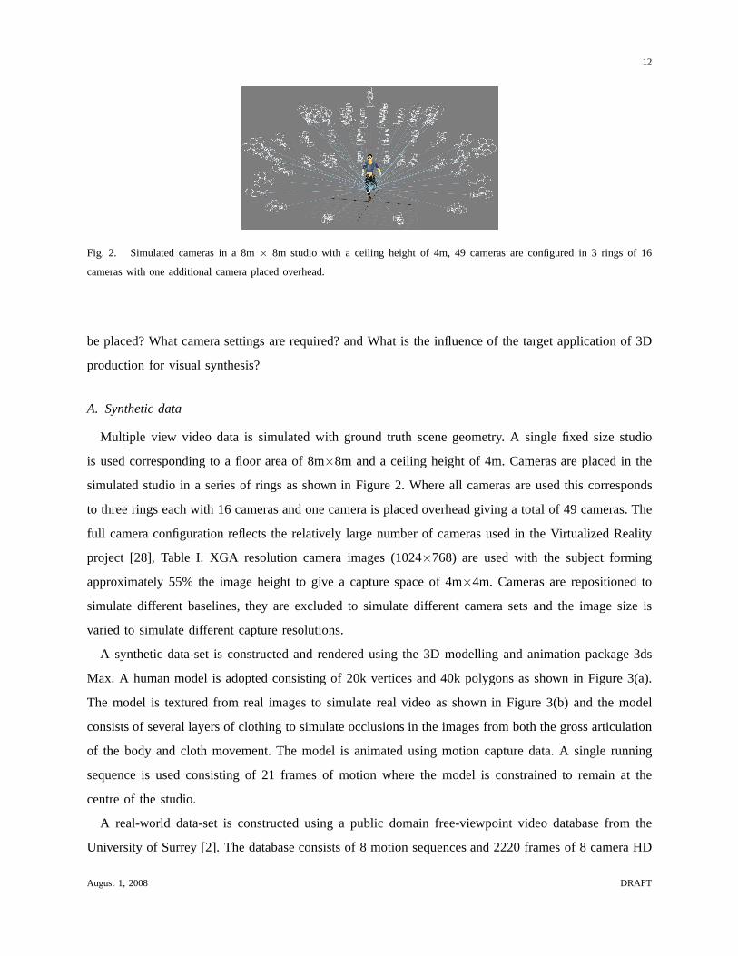
Fig. 2. Simulated cameras in a 8m× 8m studio with a ceiling height of 4m, 49 cameras are configured in 3 rings of 16
cameras with one additional camera placed overhead.
be placed? What camera settings are required? and What is theinfluence of the target application of 3D
production for visual synthesis?
A. Synthetic data
Multiple view video data is simulated with ground truth scene geometry. A single fixed size studio
is used corresponding to a floor area of 8m×8m and a ceiling height of 4m. Cameras are placed in the
simulated studio in a series of rings as shown in Figure 2. Where all cameras are used this corresponds
to three rings each with 16 cameras and one camera is placed overhead giving a total of 49 cameras. The
full camera configuration reflects the relatively large number of cameras used in the Virtualized Reality
project [28], Table I. XGA resolution camera images (1024×768) are used with the subject forming
approximately 55% the image height to give a capture space of4m×4m. Cameras are repositioned to
simulate different baselines, they are excluded to simulate different camera sets and the image size is
varied to simulate different capture resolutions.
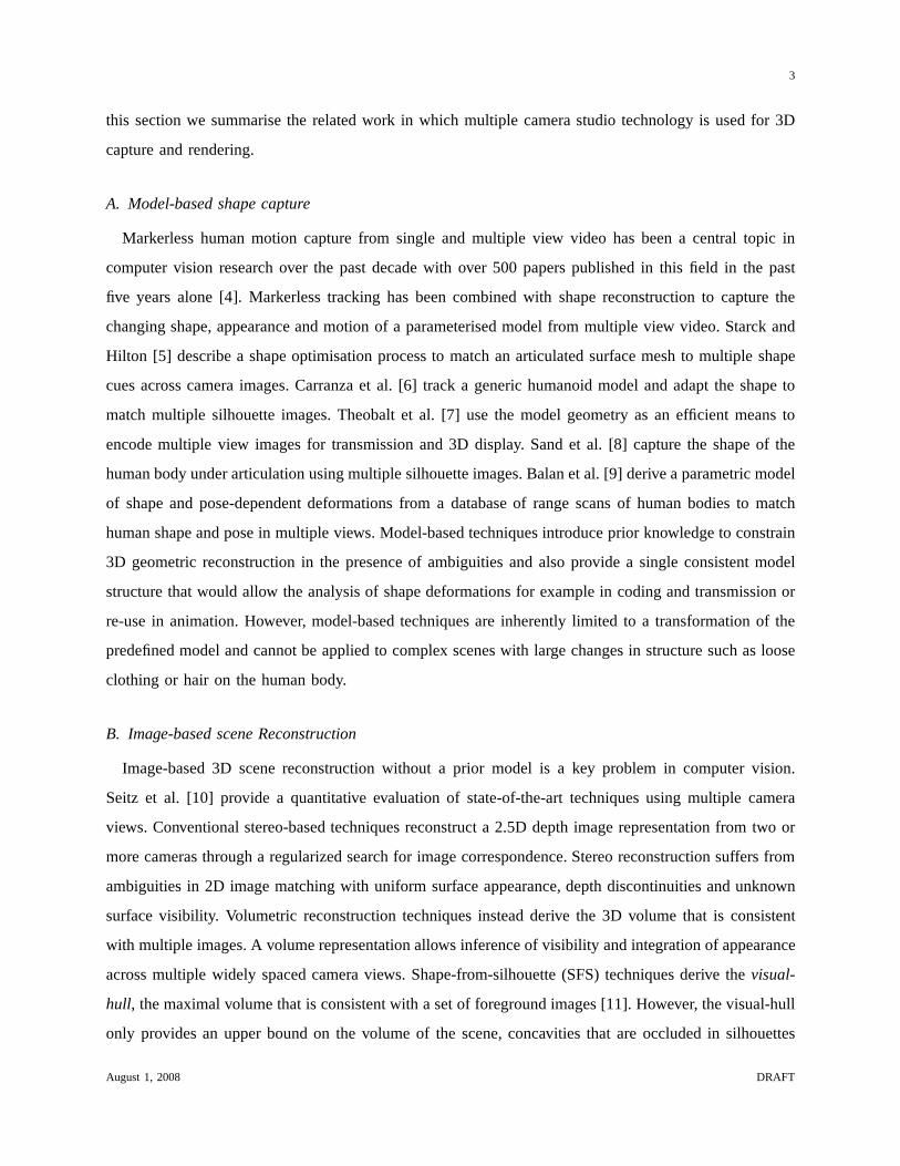
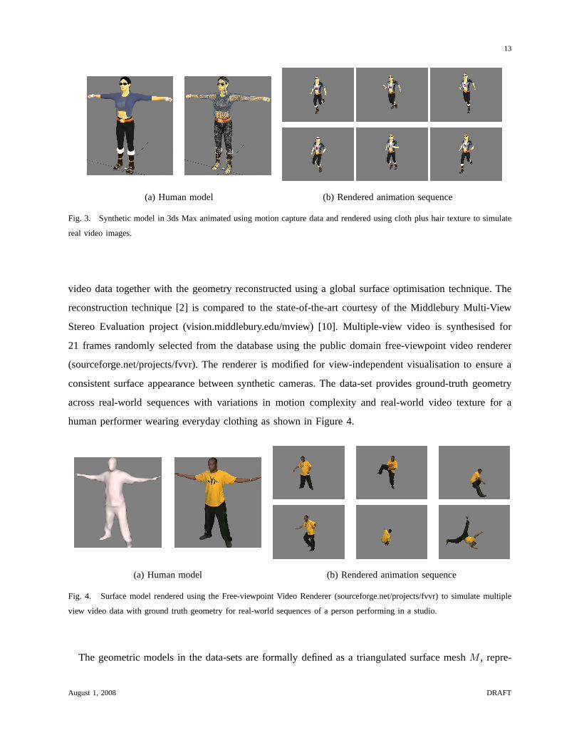
A synthetic data-set is constructed and rendered using the 3D modelling and animation package 3ds
Max. A human model is adopted consisting of 20k vertices and 40k polygons as shown in Figure 3(a).
The model is textured from real images to simulate real videoas shown in Figure 3(b) and the model
consists of several layers of clothing to simulate occlusions in the images from both the gross articulation
of the body and cloth movement. The model is animated using motion capture data. A single running
sequence is used consisting of 21 frames of motion where the model is constrained to remain at the
centre of the studio.
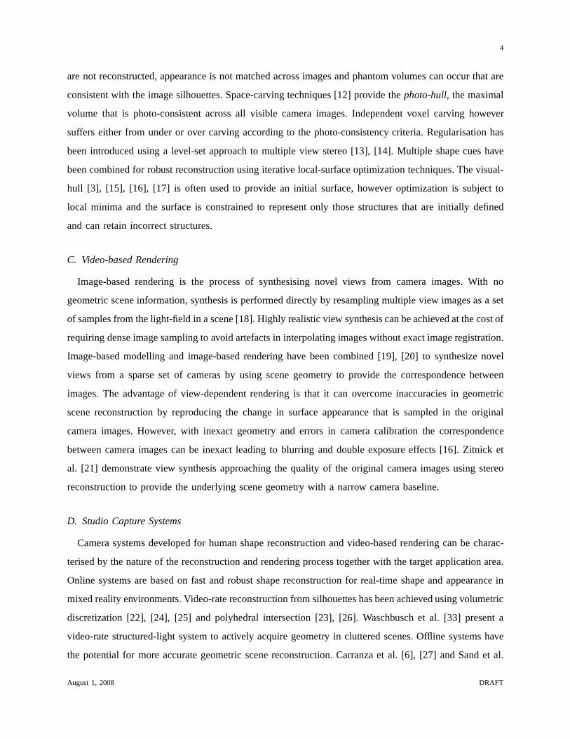
A real-world data-set is constructed using a public domain free-viewpoint video database from the
University of Surrey [2]. The database consists of 8 motion sequences and 2220 frames of 8 camera HD
August 1, 2008 DRAFT
13
(a) Human model (b) Rendered animation sequence
Fig. 3. Synthetic model in 3ds Max animated using motion capture data and rendered using cloth plus hair texture to simulate
real video images.
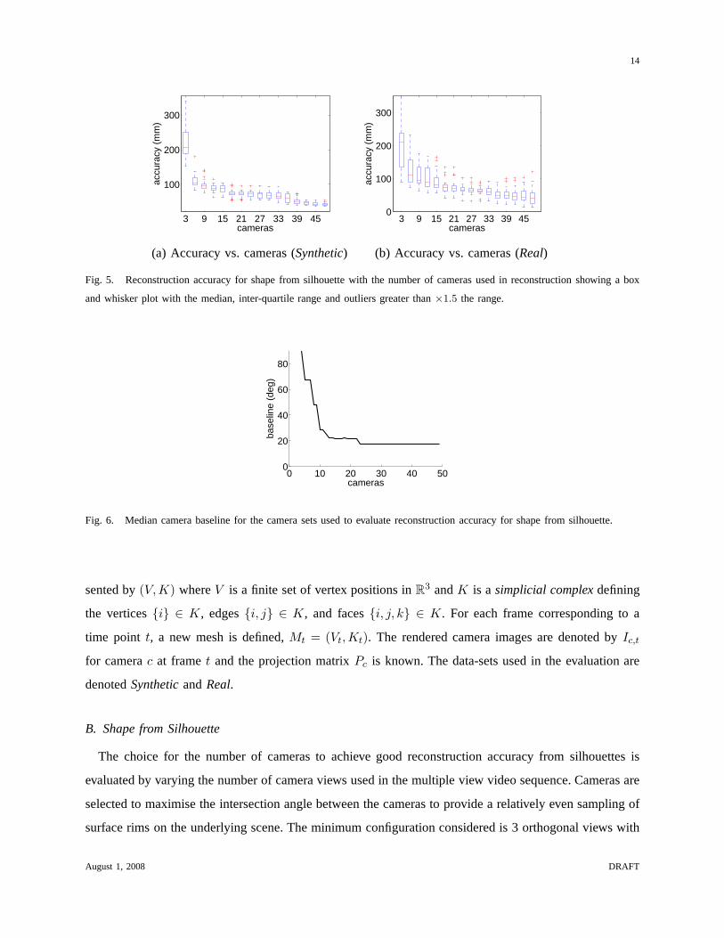
video data together with the geometry reconstructed using aglobal surface optimisation technique. The
reconstruction technique [2] is compared to the state-of-the-art courtesy of the Middlebury Multi-View
Stereo Evaluation project (vision.middlebury.edu/mview) [10]. Multiple-view video is synthesised for
21 frames randomly selected from the database using the public domain free-viewpoint video renderer
(sourceforge.net/projects/fvvr). The renderer is modified for view-independent visualisation to ensure a
consistent surface appearance between synthetic cameras.The data-set provides ground-truth geometry
across real-world sequences with variations in motion complexity and real-world video texture for a
human performer wearing everyday clothing as shown in Figure 4.
(a) Human model (b) Rendered animation sequence
Fig. 4. Surface model rendered using the Free-viewpoint Video Renderer (sourceforge.net/projects/fvvr) to simulatemultiple
view video data with ground truth geometry for real-world sequences of a person performing in a studio.
The geometric models in the data-sets are formally defined asa triangulated surface meshM , repre-
August 1, 2008 DRAFT
14
3 9 15 21 27 33 39 45
100
200
300
accu
racy
(m
m)
cameras3 9 15 21 27 33 39 45
0
100
200
300
accu
racy
(m
m)
cameras
(a) Accuracy vs. cameras (Synthetic) (b) Accuracy vs. cameras (Real)
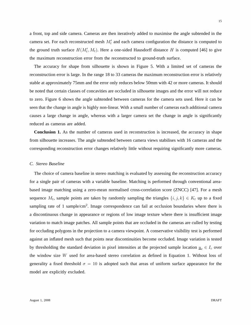
Fig. 5. Reconstruction accuracy for shape from silhouette with the number of cameras used in reconstruction showing a box
and whisker plot with the median, inter-quartile range and outliers greater than×1.5 the range.
0 10 20 30 40 500
20
40
60
80
cameras
base
line
(deg
)
Fig. 6. Median camera baseline for the camera sets used to evaluate reconstruction accuracy for shape from silhouette.
sented by(V,K) whereV is a finite set of vertex positions inR3 andK is asimplicial complexdefining
the vertices{i} ∈ K, edges{i, j} ∈ K, and faces{i, j, k} ∈ K. For each frame corresponding to a
time point t, a new mesh is defined,Mt = (Vt,Kt). The rendered camera images are denoted byIc,t
for camerac at framet and the projection matrixPc is known. The data-sets used in the evaluation are
denotedSyntheticandReal.
B. Shape from Silhouette
The choice for the number of cameras to achieve good reconstruction accuracy from silhouettes is
evaluated by varying the number of camera views used in the multiple view video sequence. Cameras are
selected to maximise the intersection angle between the cameras to provide a relatively even sampling of
surface rims on the underlying scene. The minimum configuration considered is 3 orthogonal views with
August 1, 2008 DRAFT
15
a front, top and side camera. Cameras are then iteratively added to maximise the angle subtended in the
camera set. For each reconstructed meshM ′
t and each camera configuration the distance is computed to
the ground truth surfaceH(M ′
t ,Mt). Here a one-sided Hausdorff distanceH is computed [46] to give
the maximum reconstruction error from the reconstructed toground-truth surface.
The accuracy for shape from silhouette is shown in Figure 5. With a limited set of cameras the
reconstruction error is large. In the range 18 to 33 cameras the maximum reconstruction error is relatively
stable at approximately 75mm and the error only reduces below 50mm with 42 or more cameras. It should
be noted that certain classes of concavities are occluded insilhouette images and the error will not reduce
to zero. Figure 6 shows the angle subtended between cameras for the camera sets used. Here it can be
seen that the change in angle is highly non-linear. With a small number of cameras each additional camera
causes a large change in angle, whereas with a larger camera set the change in angle is significantly
reduced as cameras are added.
Conclusion 1. As the number of cameras used in reconstruction is increased, the accuracy in shape
from silhouette increases. The angle subtended between camera views stabilises with 16 cameras and the
corresponding reconstruction error changes relatively little without requiring significantly more cameras.
C. Stereo Baseline
The choice of camera baseline in stereo matching is evaluated by assessing the reconstruction accuracy
for a single pair of cameras with a variable baseline. Matching is performed through conventional area-
based image matching using a zero-mean normalised cross-correlation score (ZNCC) [47]. For a mesh
sequenceMt, sample points are taken by randomly sampling the triangles{i, j, k} ∈ Kt up to a fixed
sampling rate of 1 sample/cm2. Image correspondence can fail at occlusion boundaries where there is
a discontinuous change in appearance or regions of low imagetexture where there is insufficient image
variation to match image patches. All sample points that areoccluded in the cameras are culled by testing
for occluding polygons in the projection to a camera viewpoint. A conservative visibility test is performed
against an inflated mesh such that points near discontinuities become occluded. Image variation is tested
by thresholding the standard deviation in pixel intensities at the projected sample locationuc ∈ Ic over
the window sizeW used for area-based stereo correlation as defined in Equation 1. Without loss of
generality a fixed thresholdσ = 10 is adopted such that areas of uniform surface appearance forthe
model are explicitly excluded.
August 1, 2008 DRAFT
16
0 10 20 30 40 508
10
12
14
16
baseline (deg)
accu
racy
(m
m)
0.00.20.40.60.8
0 10 20 30 40 5040
60
80
100
baseline (deg)
freq
uenc
y (%
)
0.00.20.40.60.8
(a) Accuracy vs. baseline (Synthetic Data) (b) Frequency vs. baseline (Synthetic Data)
0 10 20 30 40 506
8
10
12
14
16
baseline (deg)
accu
racy
(m
m)
0.00.20.40.60.8
0 10 20 30 40 5040
60
80
100
baseline (deg)
freq
uenc
y (%
)
0.00.20.40.60.8
(c) Accuracy vs. baseline (Real Data) (d) Frequency vs. baseline (Real Data)
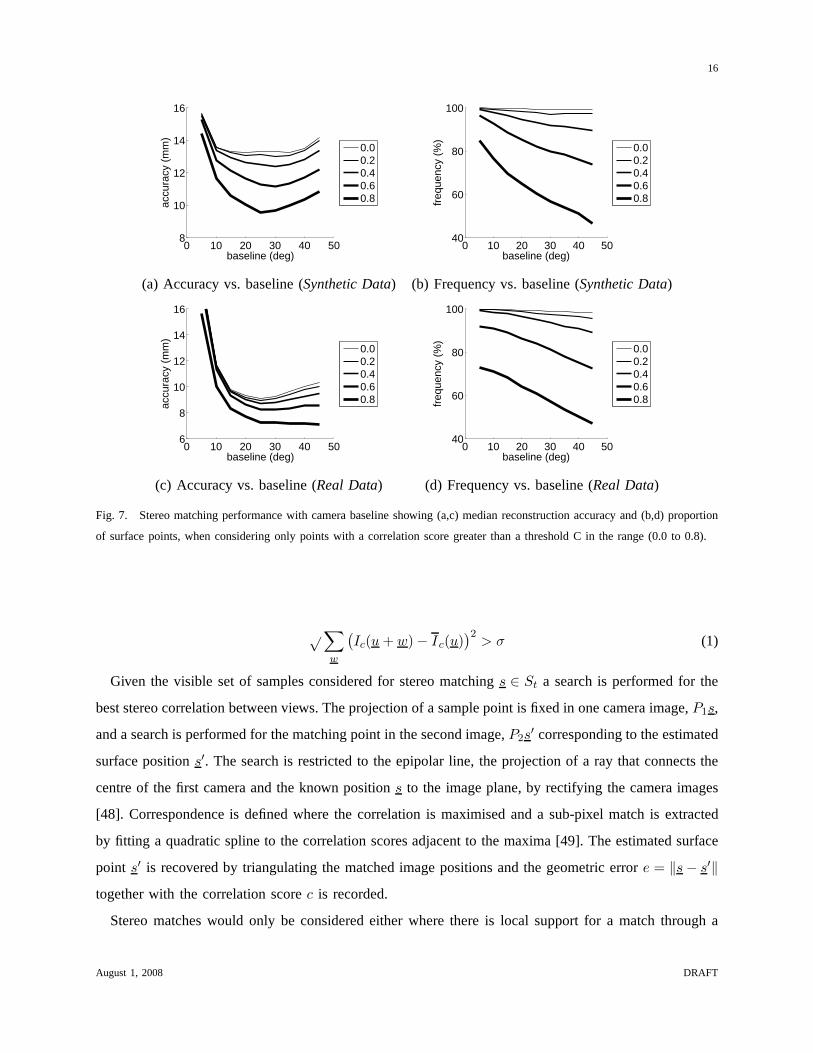
Fig. 7. Stereo matching performance with camera baseline showing (a,c) median reconstruction accuracy and (b,d) proportion
of surface points, when considering only points with a correlation score greater than a threshold C in the range (0.0 to 0.8).
√∑
w
(
Ic(u + w) − Ic(u))2
> σ (1)
Given the visible set of samples considered for stereo matching s ∈ St a search is performed for the
best stereo correlation between views. The projection of a sample point is fixed in one camera image,P1s,
and a search is performed for the matching point in the secondimage,P2s′ corresponding to the estimated
surface positions′. The search is restricted to the epipolar line, the projection of a ray that connects the
centre of the first camera and the known positions to the image plane, by rectifying the camera images
[48]. Correspondence is defined where the correlation is maximised and a sub-pixel match is extracted
by fitting a quadratic spline to the correlation scores adjacent to the maxima [49]. The estimated surface
point s′ is recovered by triangulating the matched image positions and the geometric errore = ‖s − s′‖together with the correlation scorec is recorded.
Stereo matches would only be considered either where there is local support for a match through a
August 1, 2008 DRAFT

17
regularised search for correspondence or the correlation score is sufficiently high to warrant an acceptable
match. The results are shown in Figure 7 against the threshold C for an acceptable match. Figure 7(a,c)
shows the median reconstruction accuracy for all points where c > C,C = {0.0, 0.2, 0.4, 0.6, 0.8}. It
would be expected that at a wide-baseline with a reduced depth ambiguity there is the potential for
greater accuracy but with a lower correlation score. The results show that as the thresholdC is reduced,
the minimum error point does indeed move towards a wider baseline. However the graph clearly shows
that the greatest accuracy is achieved when considering only the highest scoring matchesC = 0.8 at
a baseline of 25◦ demonstrating the trade-off between finding correct matches at a short baseline and
reducing the depth ambiguity at a wide-baseline. Figure 7(b,d) shows the proportion of sample points
that achieve the correlation threshold. Here the trade-offcan be seen between using only a high threshold
to improve reconstruction accuracy and using a low threshold to achieve dense surface reconstruction.
Conclusion 2. Optimal camera placement for stereo surface reconstruction follows the trade-off be-
tween accuracy in matching and depth ambiguity with baseline. The optimal baseline for the standard
stereo matching technique adopted is 25◦. For a planar camera ring this corresponds to 14 cameras or
more in a non-planar configuration. Accuracy will be limitedhere by the assumption of fronto-parallel
image patches and greater accuracy may be achieved by modelling the change in appearance between
viewpoints.
D. Visibility Requirements
Camera placement is now evaluated in terms of surface visibility for a single camera ring. This camera
setup is often used in the systems shown in Table I as it provides the maximum coverage from a limited
set of cameras. Surface reconstruction ideally requires the coverage of all surface regions in multiple
camera views to recover depth from image matches. View synthesis also requires coverage of all surface
regions to completely sample the surface appearance to generate new views. Visibility is determined
using a ray-tracing test. A 3D ray is cast from a point to a camera and the scene is tested for occlusions
along the ray. Surface visibility is defined for each triangle in the mesh,{i, j, k} ∈ K, as follows.
• A triangle is visible from a camerac if the ray connecting the triangle centroid and camera centre
lies within the viewing frustum of the camera and has only oneintersection, the source triangle.
• A triangle is potentially visibleif a ray exists that connects the triangle centroid and infinity, with
only one intersection corresponding to the source triangle.
Visibility is quantified as the relative proportion of visible surface area that is observed in a set of
camera images, the ratio of the area for the visible set to thearea of the potentially visible set of triangles.
August 1, 2008 DRAFT
18
0 0.5 1 1.5 2 2.5 3 3.575
80
85
90
95
100
visi
bilit
y (%
)
height (m)0 0.5 1 1.5 2 2.5 3 3.5
75
80
85
90
95
100
visi
bilit
y (%
)
height (m)
(a) Unconstrained visibility (Synthetic Data) (b) Constrained visibility (Synthetic Data)
0 0.5 1 1.5 2 2.5 3 3.575
80
85
90
95
100
visi
bilit
y (%
)
height (m)0 0.5 1 1.5 2 2.5 3 3.5
75
80
85
90
95
100
visi
bilit
y (%
)height (m)
(c) Unconstrained visibility (Real Data) (d) Constrained visibility (Real Data)
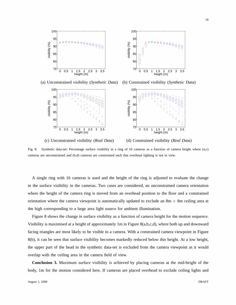
Fig. 8. Synthetic data-set: Percentage surface visibilityin a ring of 16 cameras as a function of camera height where (a,c)
cameras are unconstrained and (b,d) cameras are constrained such that overhead lighting is not in view.
A single ring with 16 cameras is used and the height of the ringis adjusted to evaluate the change
in the surface visibility in the cameras. Two cases are considered, an unconstrained camera orientation
where the height of the camera ring is moved from an overhead position to the floor and a constrained
orientation where the camera viewpoint is automatically updated to exclude an 8m× 8m ceiling area at
4m high corresponding to a large area light source for ambient illumination.
Figure 8 shows the change in surface visibility as a functionof camera height for the motion sequence.
Visibility is maximised at a height of approximately 1m in Figure 8(a,b,c,d), where both up and downward
facing triangles are most likely to be visible in a camera. With a constrained camera viewpoint in Figure
8(b), it can be seen that surface visibility becomes markedly reduced below this height. At a low height,
the upper part of the head in the synthetic data-set is excluded from the camera viewpoint as it would
overlap with the ceiling area in the camera field of view.
Conclusion 3. Maximum surface visibility is achieved by placing cameras at the mid-height of the
body, 1m for the motion considered here. If cameras are placed overhead to exclude ceiling lights and
August 1, 2008 DRAFT
19
0 10 20 30 40 500
1
2
3
baseline (deg)
erro
r (p
ixel
s) 0.00.20.40.60.8
400 600 800 1000 12000
1
2
3
resolution (lines)
accu
racy
(pi
xels
)
0.00.20.40.60.8
(a) Error vs. baseline (Synthetic Data) (b) Error vs. resolution (Synthetic Data)
0 10 20 30 40 500
0.5
1
1.5
2
baseline (deg)
erro
r (p
ixel
s) 0.00.20.40.60.8
400 600 800 1000 12000
0.5
1
1.5
2
resolution (lines)
accu
racy
(pi
xels
)
0.00.20.40.60.8
(c) Error vs. baseline (Real Data) (d) Error vs. resolution (Real Data)
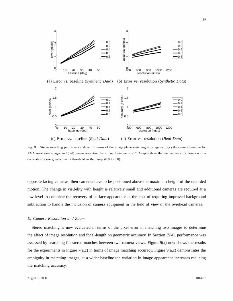
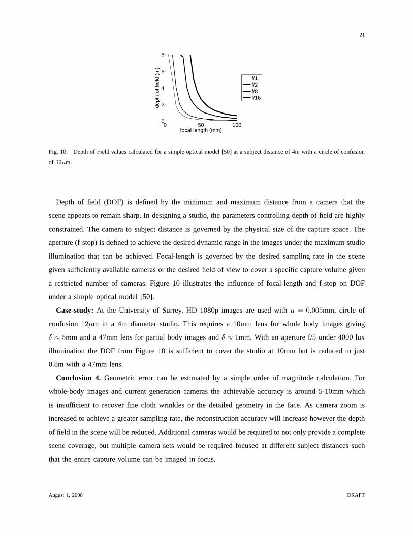
Fig. 9. Stereo matching performance shown in terms of the image plane matching error against (a,c) the camera baseline for
XGA resolution images and (b,d) image resolution for a fixed baseline of 25◦. Graphs show the median error for points with a
correlation score greater than a threshold in the range (0.0to 0.8).
opposite facing cameras, then cameras have to be positionedabove the maximum height of the recorded
motion. The change in visibility with height is relatively small and additional cameras are required at a
low level to complete the recovery of surface appearance at the cost of requiring improved background
subtraction to handle the inclusion of camera equipment in the field of view of the overhead cameras.
E. Camera Resolution and Zoom
Stereo matching is now evaluated in terms of the pixel error in matching two images to determine
the effect of image resolution and focal-length on geometric accuracy. In Section IV-C, performance was
assessed by searching for stereo matches between two cameraviews. Figure 9(a) now shows the results
for the experiments in Figure 7(a,c) in terms of image matching accuracy. Figure 9(a,c) demonstrates the
ambiguity in matching images, at a wider baseline the variation in image appearance increases reducing
the matching accuracy.
August 1, 2008 DRAFT
20
Matching accuracy is evaluated with image resolution to simulate either a corresponding change in
camera sampling rate, or an increase in focal-length where only a fixed window in the synthetic image
would actually be used. Figure 9(b,d) shows the median accuracy for resolutions of VGA (480lines),
SVGA (600lines), XGA (768lines) and SXGA+(1050lines) witha fixed aspect ratio of 4:3 and a fixed
camera baseline of 25◦. A stereo window size of 9×9, 11×11, 13×13, 17×17 is adopted respectively
to capture a consistent surface area in the images. This range of resolutions corresponds to the camera
systems used in the literature, Table I. Figure 9(b,d) demonstrates that matching accuracy decreases only
slightly with an increase in camera resolution for both the synthetic and real-world data-sets.
For an estimated image matching accuracy it is possible to formulate the expected geometric recon-
struction error. For a fixed camera baseline defined by the angle between the camera viewing directionsθ,
at a subject distance ofD (mm), a focal-length off (mm) and an effective pixel size ofµ (mm/pixel) on
the CCD, the reconstruction errorδ (mm) is governed by the matching accuracym (pixels) in Equation 2.
As an order of magnitude calculation, the median matching accuracy is estimated asm = 1 from Figure
9(b,d) for the optimal camera baselineθ = 25◦ providing a rule-of-thumb calculation for geometric error,
m/ sin(θ) = 2.4. In practise matching accuracy can increase with greater appearance variation from real
images, a higher appearance sampling rate such as a 12-bit colour depth, or it may decrease with a lower
effective sampling rate due to a bayer pattern or greater CCDnoise. The resulting reconstruction accuracy
will also decrease in practise with camera calibration error. 1
δ =mDµ
f sin θ= 2.4
Dµ
f(2)
This order of magnitude calculation gives some insight intoachievable reconstruction accuracy. With
a limited set of cameras, whole-body images are required to cover the desired capture volume. For the
studio setup considered withD = 4m and HD resolutions (1080lines), this equates toδ ≈ 5mm and at
XGA resolution (768lines)δ ≈ 10mm. This accuracy will not recover the detailed geometry in clothing
wrinkles or shallow concavities such as the eyes, but is sufficient to recover gross cloth and body shape. To
achieve a greater reconstruction accuracy the focal-length f must be increased. However, it is important
to note that this gives a restricted field of view requiring additional cameras to provide complete scene
coverage and that an increase in focal-length comes with a decrease in the depth of field in the scene.
1 At the time of writing the best case accuracy for the public domain multi-view data set presented in [10] indicates a value
of 2.1 in Equation 2 for 90% of the reconstructed surface. Thedata-set uses 16 camera views recorded from a single (hence
perfectly matched) VGA camera where the variation in appearance between views is modelled.
August 1, 2008 DRAFT
21
0 50 1000
2
4
6
8
focal length (mm)
dept
h of
fiel
d (m
)
f/1f/2f/8f/16
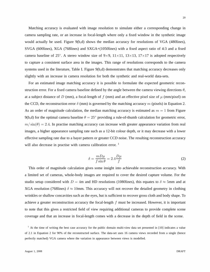
Fig. 10. Depth of Field values calculated for a simple optical model [50] at a subject distance of 4m with a circle of confusion
of 12µm.
Depth of field (DOF) is defined by the minimum and maximum distance from a camera that the
scene appears to remain sharp. In designing a studio, the parameters controlling depth of field are highly
constrained. The camera to subject distance is governed by the physical size of the capture space. The
aperture (f-stop) is defined to achieve the desired dynamic range in the images under the maximum studio
illumination that can be achieved. Focal-length is governed by the desired sampling rate in the scene
given sufficiently available cameras or the desired field of view to cover a specific capture volume given
a restricted number of cameras. Figure 10 illustrates the influence of focal-length and f-stop on DOF
under a simple optical model [50].
Case-study: At the University of Surrey, HD 1080p images are used withµ = 0.005mm, circle of
confusion12µm in a 4m diameter studio. This requires a 10mm lens for whole body images giving
δ ≈ 5mm and a 47mm lens for partial body images andδ ≈ 1mm. With an aperture f/5 under 4000 lux
illumination the DOF from Figure 10 is sufficient to cover thestudio at 10mm but is reduced to just
0.8m with a 47mm lens.
Conclusion 4. Geometric error can be estimated by a simple order of magnitude calculation. For
whole-body images and current generation cameras the achievable accuracy is around 5-10mm which
is insufficient to recover fine cloth wrinkles or the detailedgeometry in the face. As camera zoom is
increased to achieve a greater sampling rate, the reconstruction accuracy will increase however the depth
of field in the scene will be reduced. Additional cameras would be required to not only provide a complete
scene coverage, but multiple camera sets would be required focused at different subject distances such
that the entire capture volume can be imaged in focus.
August 1, 2008 DRAFT
22
F. View synthesis
Shape capture is now considered as the problem of recoveringa sufficiently accurate shape to synthesise
a new viewpoint without artefacts. Limited reconstructionaccuracy has two effects in synthesis. Firstly
the surface appearance can be inconsistent between cameraswhen the geometry is not correct and so the
appearance must be estimated from the available samples. Secondly, the appearance may be consistent but
incorrect giving an incorrect appearance when synthesising a new view. With a fixed surface appearance,
the inconsistency between cameras can be minimised by recovering appearance from the camera images
where the surface sampling rate is maximised [2]. However, afixed appearance on incorrect geometry
may not reproduce the motion parallax expected with a changein synthetic viewpoint. For example at a
10mm reconstruction accuracy the concavities at the eyes will not be recovered. If appearance is sampled
from a frontal camera where the highest sampling rate is achieved, as a virtual view moves to one side
the eyes will appear to bulge. View-dependent rendering canovercome this limitation [19], providing the
appearance of a concavity by rendering the change in appearance sampled in the camera images to the
side. However, geometric error can result in different appearance samples between the camera images
used in rendering causing in blurring and double exposure effects in view synthesis whereas the sharpest
image appearance will be provided by a single fixed surface appearance [2].
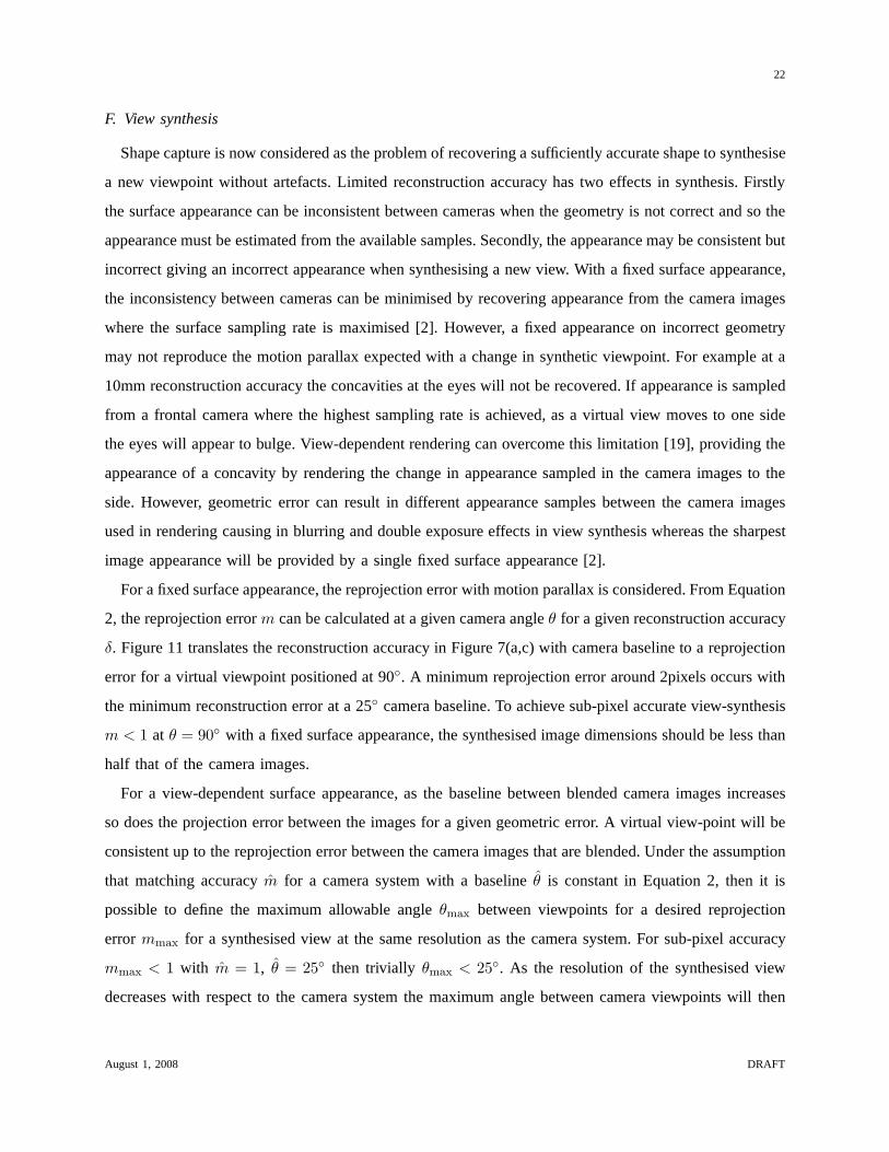
For a fixed surface appearance, the reprojection error with motion parallax is considered. From Equation
2, the reprojection errorm can be calculated at a given camera angleθ for a given reconstruction accuracy
δ. Figure 11 translates the reconstruction accuracy in Figure 7(a,c) with camera baseline to a reprojection
error for a virtual viewpoint positioned at 90◦. A minimum reprojection error around 2pixels occurs with
the minimum reconstruction error at a 25◦ camera baseline. To achieve sub-pixel accurate view-synthesis
m < 1 at θ = 90◦ with a fixed surface appearance, the synthesised image dimensions should be less than
half that of the camera images.
For a view-dependent surface appearance, as the baseline between blended camera images increases
so does the projection error between the images for a given geometric error. A virtual view-point will be
consistent up to the reprojection error between the camera images that are blended. Under the assumption
that matching accuracym for a camera system with a baselineθ is constant in Equation 2, then it is
possible to define the maximum allowable angleθmax between viewpoints for a desired reprojection
error mmax for a synthesised view at the same resolution as the camera system. For sub-pixel accuracy
mmax < 1 with m = 1, θ = 25◦ then trivially θmax < 25◦. As the resolution of the synthesised view
decreases with respect to the camera system the maximum angle between camera viewpoints will then
August 1, 2008 DRAFT
23
0 10 20 30 40 501.5
2
2.5
3
baseline (deg)
erro
r (p
ixel
s) 0.00.20.40.60.8
0 10 20 30 40 500
1
2
3
baseline (deg)
erro
r (p
ixel
s) 0.00.20.40.60.8
(c) 90◦ error vs. baseline (Synthetic Data) (d) 90◦ error vs. baseline (Real Data)
Fig. 11. Reprojection error in a virtual camera with a 90◦ view point for surface points reconstructed at different camera
baselines where correlation exceeds a threshold in the range (0.0 to 0.8).
increase.
Conclusion 5. With a fixed surface appearance sub-pixel reprojection errors in motion parallax will
only be achieved by reducing the resolution in view synthesis compared to the captured image resolution.
With a view-dependent appearance errors in motion parallaxwill be corrected and sub-pixel reprojection
errors can be achieved at the captured image resolution witha camera baseline ofθ < 25◦.
V. A COMPARISON OF TWO STUDIOS
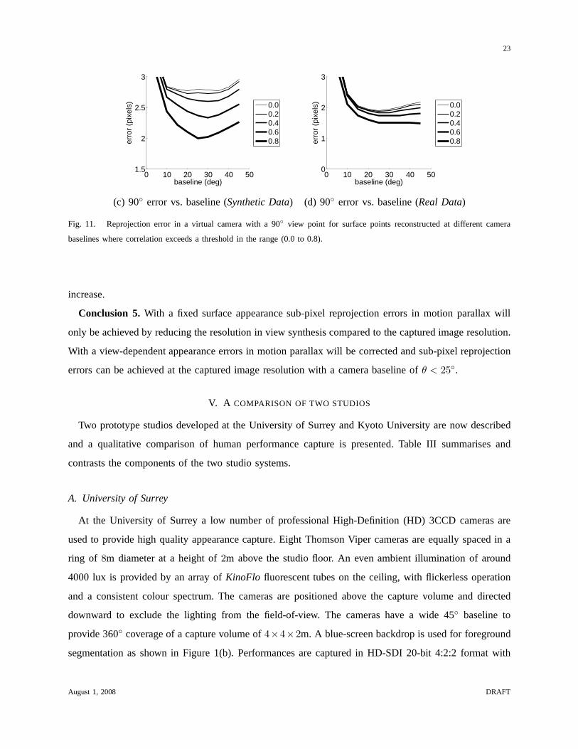
Two prototype studios developed at the University of Surreyand Kyoto University are now described
and a qualitative comparison of human performance capture is presented. Table III summarises and
contrasts the components of the two studio systems.
A. University of Surrey
At the University of Surrey a low number of professional High-Definition (HD) 3CCD cameras are
used to provide high quality appearance capture. Eight Thomson Viper cameras are equally spaced in a
ring of 8m diameter at a height of2m above the studio floor. An even ambient illumination of around
4000 lux is provided by an array ofKinoFlo fluorescent tubes on the ceiling, with flickerless operation
and a consistent colour spectrum. The cameras are positioned above the capture volume and directed
downward to exclude the lighting from the field-of-view. Thecameras have a wide 45◦ baseline to
provide 360◦ coverage of a capture volume of4×4×2m. A blue-screen backdrop is used for foreground
segmentation as shown in Figure 1(b). Performances are captured in HD-SDI 20-bit 4:2:2 format with
August 1, 2008 DRAFT
24
University of Surrey Kyoto University
Backdrop Blue-screen Grey-screen
pros Simple foreground matting Minimises coloured reflections
cons Introduces blue reflections, no blue clothing Complex shadow detection, no grey clothing
Cameras 3CCD/HD/Broadcast 1CCD/XGA/Machine vision
pros High quality, high spatial sampling Low cost, increased number of cameras
cons High cost Moderate quality
Configuration 8 camera, planar ring 15 camera, non-planar
pros 360◦ horizontal coverage 360◦ coverage, increased vertical coverage
cons Limited camera set Opposing cameras in field-of-view
Lighting Overhead fluorescents Overhead fluorescents
pros Even ambient illumination Even ambient illumination
cons Some self-shadowing Some self-shadowing
TABLE III
COMPARISON OF STUDIO COMPONENTS
1920×1080 resolution at 25Hz progressive scan. Synchronized video from all eight cameras are recorded
uncompressed direct to disk with eight dedicated PC captureboxes using DVS HD capture cards. Shape
reconstruction is performed using a global optimisation technique [2].
B. Kyoto University
At Kyoto University 15 machine vision IEEE1394a cameras areemployed to capture intangible cultural
assets. Two sets of 6 cameras are arranged in double rings of 6m diameter at heights of 1.2m and 2.2m,
respectively. An extra camera on the studio wall is dedicated to capture the face of a target subject, and
the remaining 2 cameras are placed on the ceiling. A uniform ambient illumination is provided by an
array of TRUE-LITE (850L, 5500K) fluorescent tubes as shown in Figure 1(a). The cameras in the rings
have a 30◦ baseline and provide a3 × 3 × 2m capture volume. A grey background is adopted using
grey-painted plywood panels to avoid inter-reflected colour. Performance is captured in the raw bayer
format (8bit per pixel) with 1024×768 resolution at 30Hz progressive scan. Cameras are synchronised
using an external trigger (DCAM MODE0) and raw uncompressed data (8bit XGA @ 25fps = 18.75M
bytes/sec) is recorded direct to SCSI disk via IEEE 1394a using 15 dedicated PCs. Shape reconstruction
is carried out by a surface optimization technique using a deformable mesh [3].
August 1, 2008 DRAFT
25
C. Results for human performance capture
Performance capture is now illustrated across the two studios. Two data-sets are considered, the first
recorded at the University of Surrey with a street-dancer performing fast acrobatic motions wearing
everyday clothing and the second recorded at Kyoto University for a Maiko wearing a brightly coloured
Kimono performing a slow dance. A qualitative comparison ispresented for both geometric reconstruction
[2], [3] and view synthesis using view-dependent texturing[19] from the camera images.
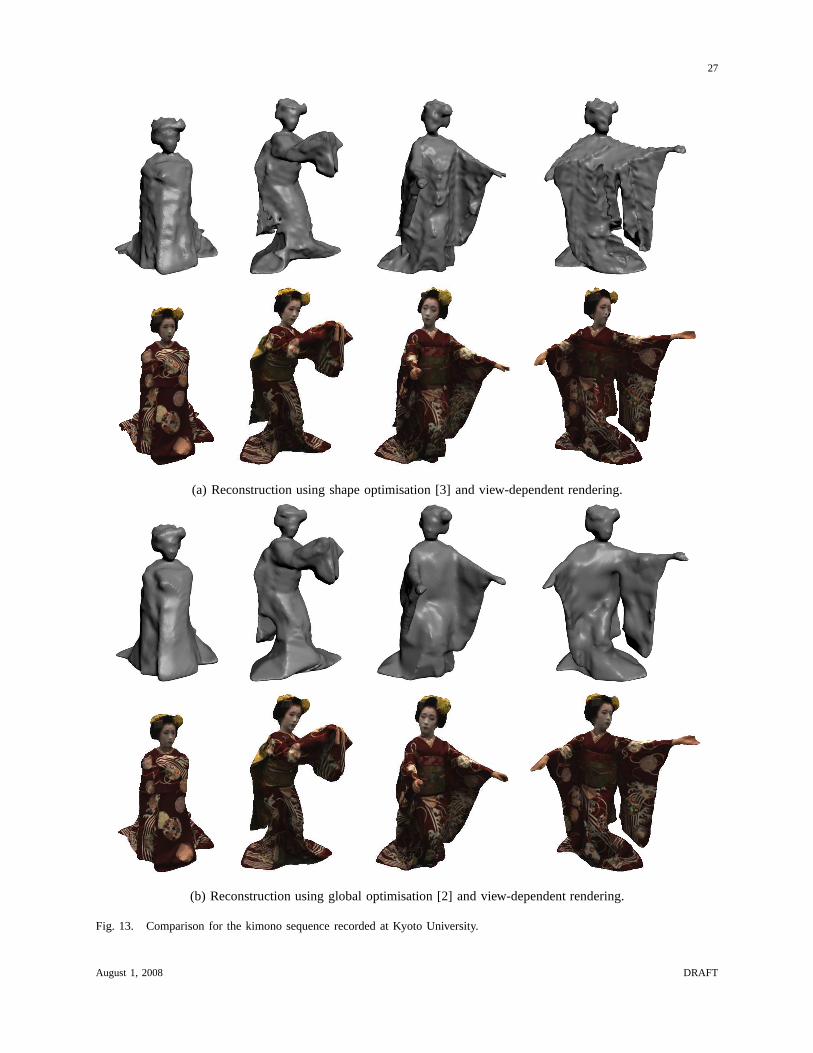
Geometric reconstruction is performed using optimisationof the visual-hull surface [3] with an average
computation time of 1 min/frame on an Intel(R) Xeon(TM) 3.6 GHz CPU and global optimisation inside
the volume defined by the visual-hull [2] with a computation time of 38 min/frame on an Intel(R)
Xeon(TM) 3GHz CPU. The reconstructed surfaces for each technique are illustrated for the two data-sets
in Figures 12(a) and 13(a). Surface optimisation provides amore efficient technique that is dependent on
the quality of the initial surface. With a limited set of cameras and multiple self-occlusions in camera
images phantom volumes can occur in the visual-hull. These structures will persist where visual cues such
as colour variation or texture are limited. Global optimisation can produce a more accurate reconstruction
at a higher computational cost.
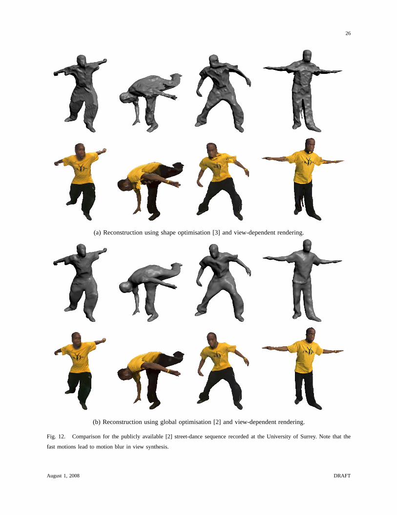
Figures 12(b), 13(b) show view synthesis not aligned with the original camera viewpoints for the
reconstructed geometry. Where geometric shape is exact, the surface appearance will be blended correctly
across the camera images up to the calibration accuracy of the camera system. Geometric errors can
lead to incorrect blending of sampled appearance and incorrect estimation of surface visibility in the
camera images. For the fast motions in Figure 12 any blur arising from small scale geometric error
is masked by the motion blur in the original camera images. However, gross geometric errors arising
from phantom structures lead to incorrect samples of surface appearance from the images and incorrect
structures becoming apparent in view synthesis. Geometricreconstruction should recover a sufficiently
accurate scene representation for view synthesis in terms of both the rendered surface appearance and
the rendered shape, the outline of the rendered scene.
VI. CONCLUSION
Achieving high quality 3D reconstruction represents a significant challenge in a multiple camera
production studio. The different design decisions in constructing a studio have been presented and two
real studios have been compared. A ground truth evaluation for the impact of geometric reconstruction
accuracy has been performed to provide a quantified insight into the effect of different choices governing
August 1, 2008 DRAFT
26
(a) Reconstruction using shape optimisation [3] and view-dependent rendering.
(b) Reconstruction using global optimisation [2] and view-dependent rendering.
Fig. 12. Comparison for the publicly available [2] street-dance sequence recorded at the University of Surrey. Note that the
fast motions lead to motion blur in view synthesis.
August 1, 2008 DRAFT
27
(a) Reconstruction using shape optimisation [3] and view-dependent rendering.
(b) Reconstruction using global optimisation [2] and view-dependent rendering.
Fig. 13. Comparison for the kimono sequence recorded at Kyoto University.
August 1, 2008 DRAFT
28
the multiple camera capture system. The following conclusions are made based on the practical experience
in the two studios and the ground truth evaluation.
The studio backdrop should be chosen to give the maximum contrast with the foreground scene for
accurate foreground matting with the minimum impact of the content of the scene. The maximum amount
of consistent ambient illumination is required in the studio to allow for a fast camera shutter speed to
reduce motion blur and a small aperture to increase the depthof field in the scene. Lights should ideally
be placed out of the field of view of the cameras to prevent saturation and blooming. Accurate geometric
camera calibration is a prerequisite for 3D shape reconstruction and photometric correction should be
performed between cameras to match the sampled appearance between camera viewpoints.
High-quality professional cameras and lenses are requiredto maximise the sampling resolution to
increase geometric accuracy, surface sampling rate and dynamic range for a scene, however this comes
at an increase in cost. Low-cost machine vision cameras can be used to provide more cameras for a
given budget. With more cameras a restricted field of view canthen be used to increase the effective
sampling rate for the scene. However, the number of cameras may be significant as the entire scene must
be sampled within the depth of field for the cameras.
Cameras can be placed in an overhead position to remove opposing cameras and overhead lighting
from the field of view. Reducing the camera height has relatively little effect on visibility and surface
appearance can only be completed by including low level cameras with the disadvantage of including the
equipment and lighting within the field of view of the camera system. Fixed cameras provide coverage
of a predefined limited capture volume. The capture volume can be extended using multiple camera sets
or through an active vision system using object tracking.
The ideal baseline between camera views for both stereo reconstruction and shape-from-silhouette
was found to be 25 degrees. Non-coplanar cameras improve thereconstruction accuracy for shape-from-
silhouette. Where the entire scene is within the field of viewthis corresponds to 16 cameras. Wider-
baseline configurations up to 45 degrees are however feasible using global optimisation techniques.
Ground-truth experiments demonstrate that the median image matching accuracy using stereo cor-
respondence is in the order of the pixel size for the camera images. This provides a rule-of-thumb
formula for reconstruction accuracy. With current generation cameras and whole-body images of people
the achievable accuracy is in the order of 5-10mm. Accuracy will only be improved by increasing the
resolution of the camera system or using multiple camera sets with a restricted field-of-view to increase
the sampling rate in the scene.
A 5-10mm accurate reconstruction is insufficient to recoverthe detailed geometry at the face, hands
August 1, 2008 DRAFT
29
and fine cloth wrinkles. With limited accuracy the goal of performance capture should be to recover a
sufficiently accurate representation to synthesise content without artefacts. With a fixed surface appearance
this can require a reduction in the output resolution for thesynthesised view. However, view dependent
rendering will allow synthesis at the sampling rate of the original camera images but with some reduction
in quality due to blurring of the appearance sampled in different camera views.
In summary, where the number of cameras is restricted the ideal configuration would make use of
16 cameras positioned in a non-planar configuration surrounding a capture area. Lighting can be placed
overhead to provide an even ambient illumination. Cameras should be positioned at mid-height level
subject to excluding the lighting from the field-of-view andhandling opposite facing cameras within the
field-of-view. Cameras should be selected to maximise the sampling resolution of the scene. The feasible
capture volume is constrained by the depth-of-field that canbe achieved with the cameras and lighting.
Visualisation then requires view dependent rendering where the output display resolution mirrors the
camera resolution.
ACKNOWLEDGMENT
This work was supported by the Daiwa Anglo-Japanese Foundation, EPSRC UK Visual Media Research
Platform Grant GR/S46543 and the MEXT Japan Leading ProjectGrant in Development of High Fidelity
Digitization Software for Large-Scale and Intangible Cultural Assets.
REFERENCES
[1] T. Kanade, P. Rander, and P. Narayanan, “Virtualized reality: Constructing virtual worlds from real scenes,”IEEE
Multimedia, vol. 4(1), pp. 34–47, 1997.
[2] J. Starck and A. Hilton, “Surface capture for performance based animation,”IEEE Computer Graphics and Applications,
vol. 27(3), pp. 21–31, 2007.
[3] T. Matsuyama, X. Wu, T. Takai, and S. Nobuhara, “Real-time 3D shape reconstruction, dynamic 3D mesh deformation,
and high fidelity visualization for 3D video,”Computer Vision and Image Understanding, vol. 96(3), pp. 393–434, 2004.
[4] T. Moeslund, A. Hilton, and V. Kruger, “A survey of advances in video-based human motion capture and analysis,”
Computer Vision and Image Understanding, vol. 104, pp. 90–126, 2006.
[5] J. Starck and A. Hilton, “Model-based multiple view reconstruction of people,”IEEE International Conference on Computer
Vision (ICCV), pp. 915–922, 2003.
[6] J. Carranza, C. M. Theobalt, M. Magnor, and H. Seidel, “Free-viewpoint video of human actors,”ACM Transactions on
Graphics (SIGGRAPH), vol. 22(3), pp. 569–577, 2003.
[7] C. Theobalt, G. Ziegler, M. Magnor, and H.-P. Seidel, “Model-based free-viewpoint video: Acquisition, rendering,and
encoding,”Picture Coding Symposium (PCS), vol. 5, pp. 1–6, 2004.
August 1, 2008 DRAFT
30
[8] P. Sand, L. McMillan, and J. Popovic, “Continuous capture of skin deformation,”ACM Transactions on Graphics
(SIGGRAPH), pp. 578–586, 2003.
[9] A. Balan, L. Sigal, M. Black, J. Davis, and H. Haussecker,“Detailed human shape and pose from images,”to appear
Computer Vision and Pattern Recognition (CVPR), 2007.
[10] S. Seitz, B. Curless, J. Diebel, D. Scharstein, and R. Szeliski, “A comparison and evaluation of multi-view stereo
reconstruction algorithms,”IEEE International Conference on Computer Vision and Pattern Recognition (CVPR), vol. 1,
pp. 519–526, 2006.
[11] A. Laurentini, “The visual hull concept for silhouettebased image understanding,”IEEE Transactions on Pattern Analysis
and Machine Intelligence, vol. 16(2), pp. 150–162, 1994.
[12] K. Kutulakos and S. Seitz, “A theory of shape by space carving,” International Journal of Computer Vision, vol. 38(3),
pp. 199–218, 2000.
[13] O. Faugeras and R. Keriven, “Variational principles, surface evolution, pde’s, level set methods and the stereo problem,”
IEEE Transactions on Image Processing, vol. 7(3), pp. 336–344, 1998.
[14] B. Goldluecke and M. Magnor, “Space-time isosurface evolution for temporally coherent 3D reconstruction,”IEEE
International Conference on Computer Vision and Pattern Recognition (CVPR), vol. I, pp. 350–355, 2004.
[15] C. Esteban and F. Schmitt, “Silhouette and stereo fusion for 3D object modeling,”Computer Vision and Image
Understanding, vol. 96(3), pp. 367–392, 2004.
[16] J. Starck and A. Hilton, “Virtual view synthesis of people from multiple view video sequences,”Graphical Models, vol.
67(6), pp. 600–620, 2005.
[17] Y. Furukawa and J. Ponce, “Carved visual hulls for image-based modeling,”European Conference on Computer Vision
(ECCV), pp. I: 564–577, 2006.
[18] M. Levoy and P. Hanrahan, “Light field rendering,”ACM Transactions on Graphics (SIGGRAPH), vol. 30, pp. 31–42,
1996.
[19] P. Debevec, Y. Yu, and G. Borshukov, “Efficient view-dependent image-based rendering with projective texture-mapping,”
Proceedings of Eurographics Workshop on Rendering,, pp. 105–116, 1998.
[20] C. Buehler, M. Bosse, L. McMillan, S. Gortler, and M. Cohen, “Unstructured lumigraph rendering,”ACM Transactions
on Graphics (SIGGRAPH), pp. 425–432, 2001.
[21] C. Zitnick, S. B. Kang, M. Uyttendaele, S. A. J. Winder, and R. Szeliski, “High-quality video view interpolation using a
layered representation,”ACM Transactions on Graphics (SIGGRAPH), vol. 23(3), pp. 600–608, 2004.
[22] G. Cheung, T. Kanade, J. Bouguet, and M. Holler, “A real time system for robust 3D voxel reconstruction of human
motions,” IEEE International Conference on Computer Vision and Pattern Recognition (CVPR), pp. 714–720, 2000.
[23] W. Matusik, C. Buehler, and L. Mcmillan, “Polyhedral visual hulls for real-time rendering,”Proceedings of Eurographics
Workshop on Rendering,, pp. 115–126, 2001.
[24] O. Grau, T. Pullen, and G. Thomas, “A combined studio production system for 3D capturing of live action and immersive
actor feedback,”IEEE Transactions on Circuits and Systems for Video Technology, vol. 14(3), pp. 370–380, 2003.
[25] J.-M. Hasenfratz, M. Lapierre, and F. Sillion, “A real-time system for full body interaction with virtual worlds,”
Eurographics Symposium on Virtual Environments, pp. 147–156, 2004.
[26] J. Allard, J.-S. Franco, C. Menier, E. Boyer, and B. Raffin, “The grimage platform: A mixed reality environment for
interactions,”IEEE International Conference on Computer Vision Systems (ICVS), p. 46, 2006.
August 1, 2008 DRAFT
31
[27] C. Theobalt, M. Li, M. Magnor, and H.-P. Seidel, “A flexible and versatile studio for synchronized multi-view video
recording,”Vision, Video, and Graphics, pp. 9–16, 2003.
[28] T. Kanade, H. Saito, and S. Vedula, “Digitizing time-varying 3D events by synchronized multiple video streams,”Technical
Report CMU-RI-TR-98-34, Robotics Institute, Carnegie Mellon University, 1998.
[29] K. Cheung, S. Baker, and T. Kanade, “Silhouette across time: Part ii: Applications to human modeling and markerless
motion tracking,”International Journal of Computer Vision, vol. 63(3), pp. 225–245, 2005.
[30] C. Zhang and T. Chen, “A self-reconfigurable camera array,” Eurographics Symposium on Rendering, pp. 243–254, 2004.
[31] W. Matusik and H. Pfister, “3D TV: a scalable system for real-time acquisition, transmission, and autostereoscopicdisplay
of dynamic scenes,”ACM Transactions on Graphics (SIGGRAPH), pp. 814–824, 2004.
[32] M. Tanimoto, “FTV (free viewpoint television) for 3D scene reproduction and creation,”IEEE Conference on Computer
Vision and Pattern Recognition Workshop (CVPRW), p. 172, 2006.
[33] M. Waschbusch, S. Wurmlin, D. Cotting, F. Sadlo, and M. Gross, “Scalable 3D video of dynamic scenes,”The Visual
Computer, vol. 21(8-10), pp. 629–638, 2005.
[34] J.-S. Franco, M. Lapierre, and E. Boyer, “Visual shapesof silhouette sets,”International Symposium on 3D Data Processing,
Visualization and Transmission (3DPVT), pp. 397–404, 2006.
[35] K. Tomiyama, Y. Orihara, M. Katayama, and Y. Iwadate, “Algorithm for dynamic 3D object generation from multi-viewpoint
images,”Proceedings of the SPIE, vol. 5599(19), pp. 153–161, 2004.
[36] Y. Boykov and V. Kolmogorov, “Computing geodesics and minimal surfaces via graph cuts,”IEEE International Conference
on Computer Vision (ICCV), pp. 26–33, 2003.
[37] S. Vedula, S. Baker, and T. Kanade, “Image-based spatio-temporal modeling and view interpolation of dynamic events,”
ACM Transactions on Graphics, vol. 24(2), pp. 240–261, 2005.
[38] Y.-Y. Chuang, B. Curless, D. Salesin, and R. Szeliski, “A Bayesian approach to digital matting,”IEEE Conference on
Computer Vision and Pattern Recognition (CVPR), pp. 264–271, 2001.
[39] N. Ukita and T. Matsuyama, “Real-time cooperative multi-target tracking by communicating active vision agents,”Computer
Vision and Image Understanding, vol. 97(2), pp. 137–179, 2005.
[40] R. Tsai, “An efficient and accurate camera calibration technique for 3D machine vision,”IEEE Conference on Computer
Vision and Pattern Recognition (CVPR), pp. 364–374, 1986.
[41] Z. Zhang, “A flexible new technique for camera calibration,” IEEE Transactions on Pattern Analysis and Machine
Intelligence, vol. 22(11), pp. 1330–1334, 2000.
[42] R. I. Hartley and A. Zisserman,Multiple View Geometry in Computer Vision, 2nd ed. Cambridge University Press, 2004.
[43] T. Svoboda, D. Martinec, and T. Pajdla, “A convenient multicamera self-calibration for virtual environments,”Presence:
Teleoper. Virtual Envrion, vol. 14(4), pp. 407–422, 2005.
[44] J. Mitchelson and A. Hilton, “Wand-based multiple camera studio calibration,”CVSSP Technical Report, vol. VSSP-TR-
2/2003, 2003.
[45] A. Wenger, T. Hawkins, and P. Debevec, “Optimizing color matching in a lighting reproduction system for complex subject
and illuminant spectra,”Eurographics workshop on Rendering, pp. 249–259, 2003.
[46] P. Cignoni, C. Rocchini, and R. Scopigno, “Metro: measuring error on simplified surfaces,”Computer Graphics Forum,
vol. 17(2), pp. 167–174, 1998.
[47] O. Faugeras, B. Hotz, H. Mathieu, T. Vieville, Z. Zhang,P. Fua, E. Theron, L. Moll, G. Berry, J. Vuillemin, P. Bertin,and
C. Proy, “Real time correlation based stereo: algorithm implementations and applications,”INRIA Report 2013, 1993.
August 1, 2008 DRAFT

32
[48] A. Fusiello, E. Trucco, and A. Verri, “Rectification with unconstrained stereo geometry,”British Machine Vision Conference
(BMVC), pp. 400–409, 1997.
[49] A. Fusiello, V. Roberto, and E. Trucco, “Symmetric stereo with multiple windowing,”International Journal of Pattern
Recognition and Artificial Intelligence, vol. 14(8), pp. 1053–1066, 2000.
[50] A. R. Greenleaf, “Photographic optics,”The MacMillan Company, New York, pp. 25–27, 1950.
August 1, 2008 DRAFT