Embed Size (px)
Citation preview

1
WASP-lite Design Review
April 15, 2005
Prepared by:
Michael Richardson
Jason Faulring
2
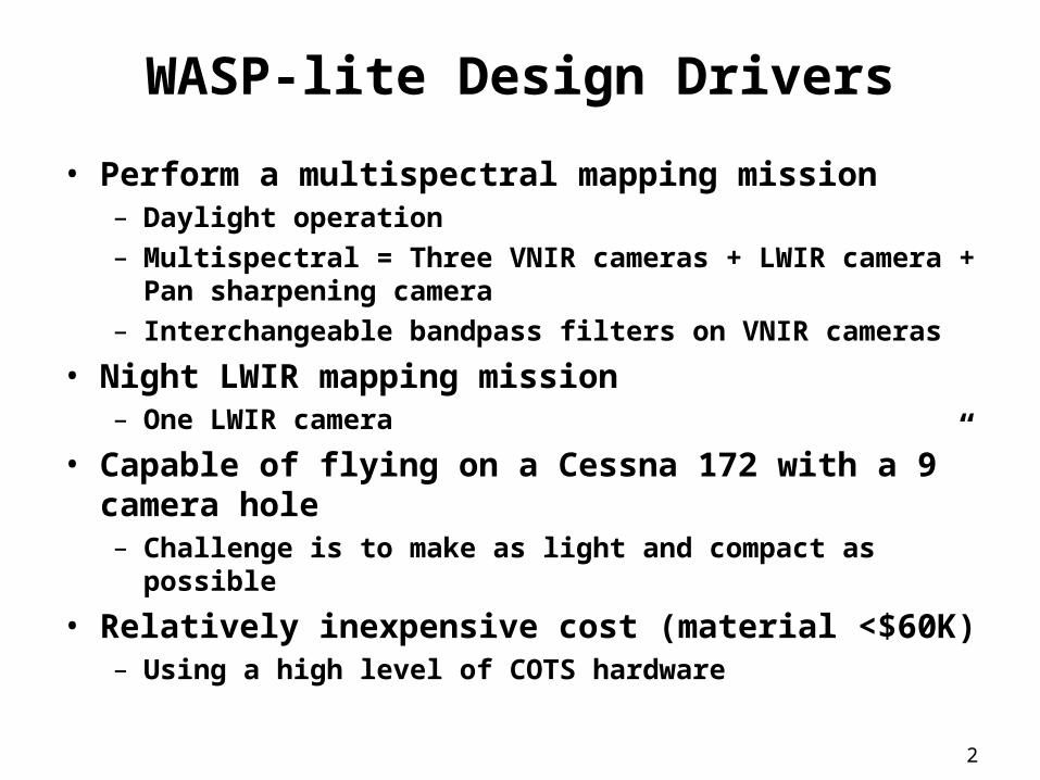
WASP-lite Design Drivers
• Perform a multispectral mapping mission– Daylight operation– Multispectral = Three VNIR cameras + LWIR camera + Pan
sharpening camera– Interchangeable bandpass filters on VNIR cameras
• Night LWIR mapping mission– One LWIR camera
• Capable of flying on a Cessna 172 with a 9” camera hole– Challenge is to make as light and compact as possible
• Relatively inexpensive cost (material <$60K)– Using a high level of COTS hardware
3
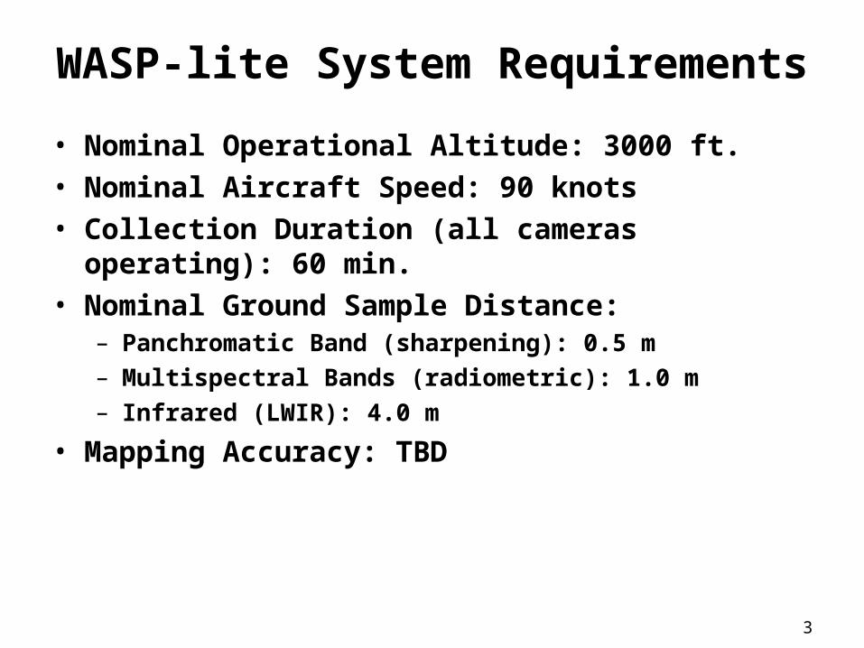
WASP-lite System Requirements
• Nominal Operational Altitude: 3000 ft.• Nominal Aircraft Speed: 90 knots• Collection Duration (all cameras operating): 60 min.• Nominal Ground Sample Distance:
– Panchromatic Band (sharpening): 0.5 m– Multispectral Bands (radiometric): 1.0 m– Infrared (LWIR): 4.0 m
• Mapping Accuracy: TBD
4
WASP-lite Design Configuration
5
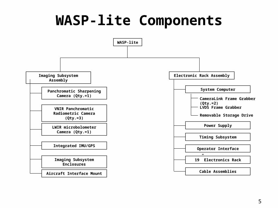
WASP-lite ComponentsWASP-lite
Panchromatic Sharpening Camera (Qty.=1)
Imaging Subsystem Assembly
VNIR Panchromatic Radiometric Camera (Qty.=3)
LWIR microbolometer Camera (Qty.=1)
Integrated IMU/GPS
Imaging Subsystem Enclosures
Aircraft Interface Mount
Electronic Rack Assembly
System Computer
CameraLink Frame Grabber (Qty.=2)
Removable Storage Drive
Power Supply
Operator Interface
19” Electronics Rack
LVDS Frame Grabber
Timing Subsystem
Cable Assemblies
6
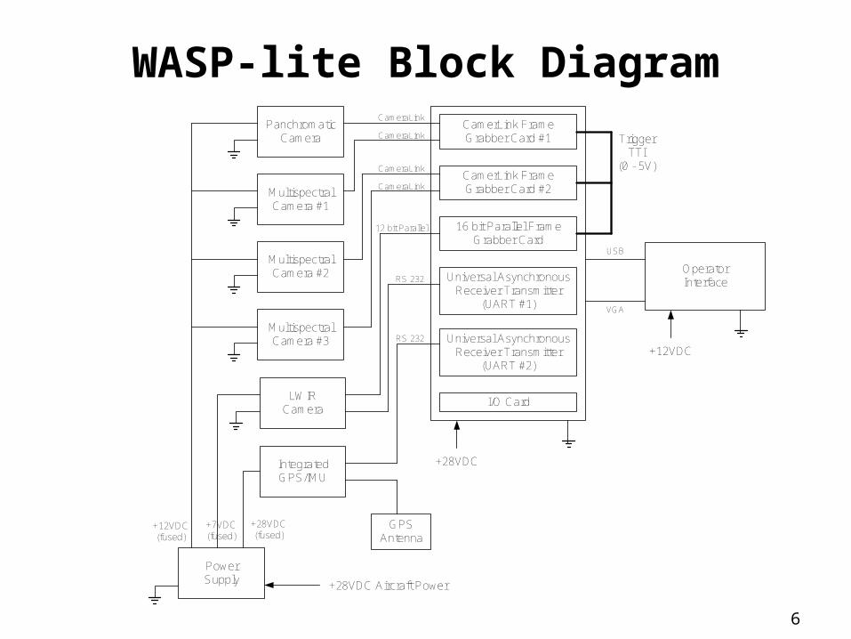
WASP-lite Block DiagramPanchromatic
Camera
MultispectralCamera #1
MultispectralCamera #2
MultispectralCamera #3
LWIRCamera
PowerSupply
IntegratedGPS/IMU
+28VDC(fused)
GPSAntenna
CamerLink FrameGrabber Card #1
CamerLink FrameGrabber Card #2
16 bit Parallel FrameGrabber Card
Universal AsynchronousReceiver Transmitter
(UART #1)
Universal AsynchronousReceiver Transmitter
(UART #2)
I/O Card
+28VDC
CameraLink
CameraLink
CameraLink
CameraLink
OperatorInterface
12 bit Parallel
RS 232
RS 232
VGA
USB
+12VDC
+28VDC Aircraft Power
TriggerTTI
(0 - 5V)
+7VDC(fused)
+12VDC(fused)

7
Detailed Design:
Imaging Subsystem Assembly
8
WASP-lite Component Design
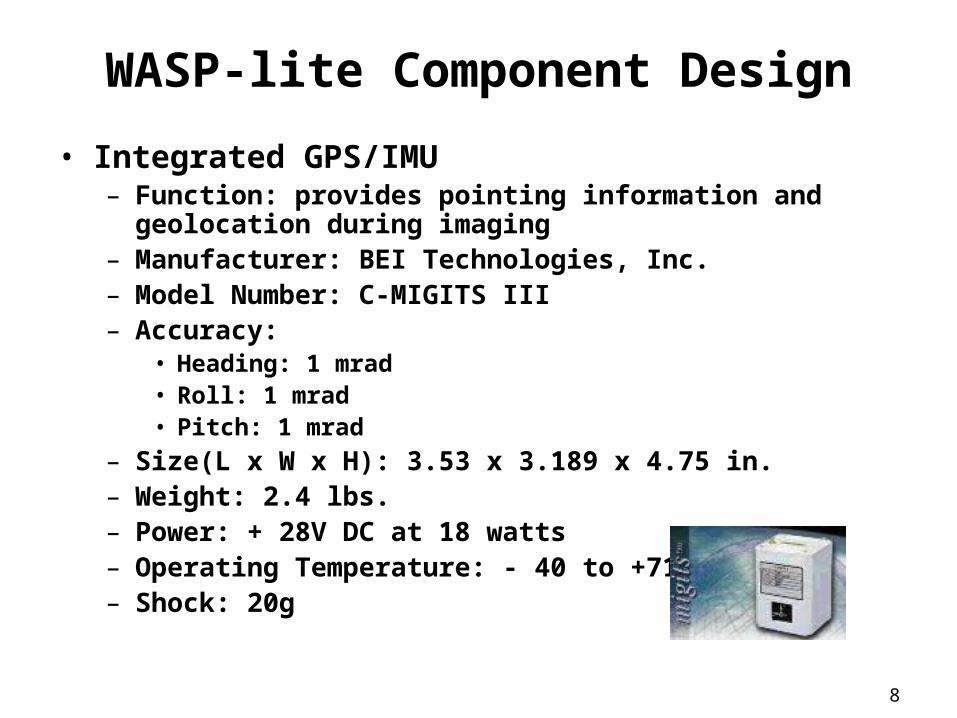
• Integrated GPS/IMU– Function: provides pointing information and geolocation
during imaging– Manufacturer: BEI Technologies, Inc.– Model Number: C-MIGITS III– Accuracy:
• Heading: 1 mrad• Roll: 1 mrad• Pitch: 1 mrad
– Size(L x W x H): 3.53 x 3.189 x 4.75 in.– Weight: 2.4 lbs.– Power: + 28V DC at 18 watts– Operating Temperature: - 40 to +71 oC– Shock: 20g
9
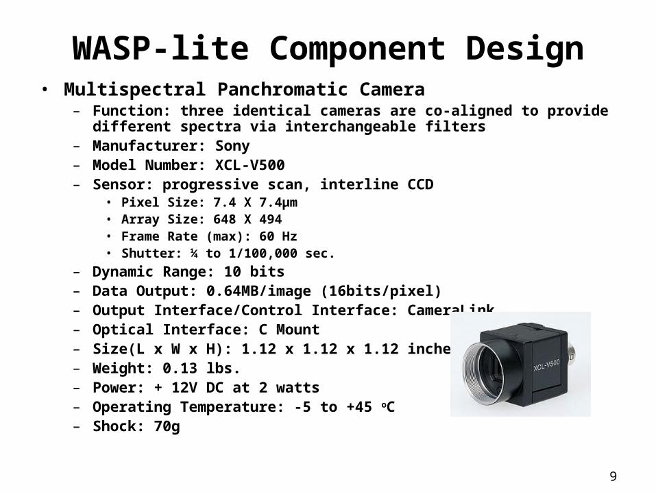
WASP-lite Component Design• Multispectral Panchromatic Camera
– Function: three identical cameras are co-aligned to provide different spectra via interchangeable filters
– Manufacturer: Sony– Model Number: XCL-V500– Sensor: progressive scan, interline CCD
• Pixel Size: 7.4 X 7.4µm• Array Size: 648 X 494• Frame Rate (max): 60 Hz• Shutter: ¼ to 1/100,000 sec.
– Dynamic Range: 10 bits– Data Output: 0.64MB/image (16bits/pixel)– Output Interface/Control Interface: CameraLink– Optical Interface: C Mount– Size(L x W x H): 1.12 x 1.12 x 1.12 inches– Weight: 0.13 lbs.– Power: + 12V DC at 2 watts– Operating Temperature: -5 to +45 oC– Shock: 70g
10
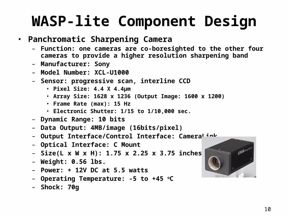
WASP-lite Component Design• Panchromatic Sharpening Camera
– Function: one cameras are co-boresighted to the other four cameras to provide a higher resolution sharpening band
– Manufacturer: Sony– Model Number: XCL-U1000– Sensor: progressive scan, interline CCD
• Pixel Size: 4.4 X 4.4µm• Array Size: 1628 x 1236 (Output Image: 1600 x 1200)• Frame Rate (max): 15 Hz• Electronic Shutter: 1/15 to 1/10,000 sec.
– Dynamic Range: 10 bits– Data Output: 4MB/image (16bits/pixel)– Output Interface/Control Interface: CameraLink– Optical Interface: C Mount– Size(L x W x H): 1.75 x 2.25 x 3.75 inches– Weight: 0.56 lbs.– Power: + 12V DC at 5.5 watts– Operating Temperature: -5 to +45 oC– Shock: 70g
11
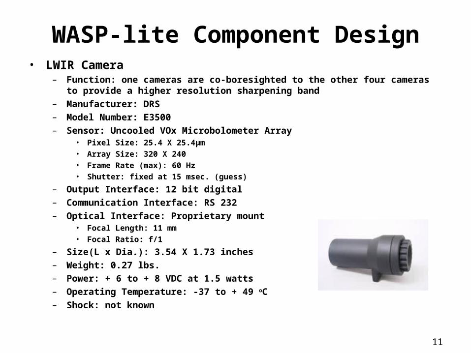
WASP-lite Component Design• LWIR Camera
– Function: one cameras are co-boresighted to the other four cameras to provide a higher resolution sharpening band
– Manufacturer: DRS
– Model Number: E3500
– Sensor: Uncooled VOx Microbolometer Array• Pixel Size: 25.4 X 25.4µm• Array Size: 320 X 240• Frame Rate (max): 60 Hz• Shutter: fixed at 15 msec. (guess)
– Output Interface: 12 bit digital
– Communication Interface: RS 232
– Optical Interface: Proprietary mount• Focal Length: 11 mm• Focal Ratio: f/1
– Size(L x Dia.): 3.54 X 1.73 inches
– Weight: 0.27 lbs.
– Power: + 6 to + 8 VDC at 1.5 watts
– Operating Temperature: -37 to + 49 oC
– Shock: not known
12
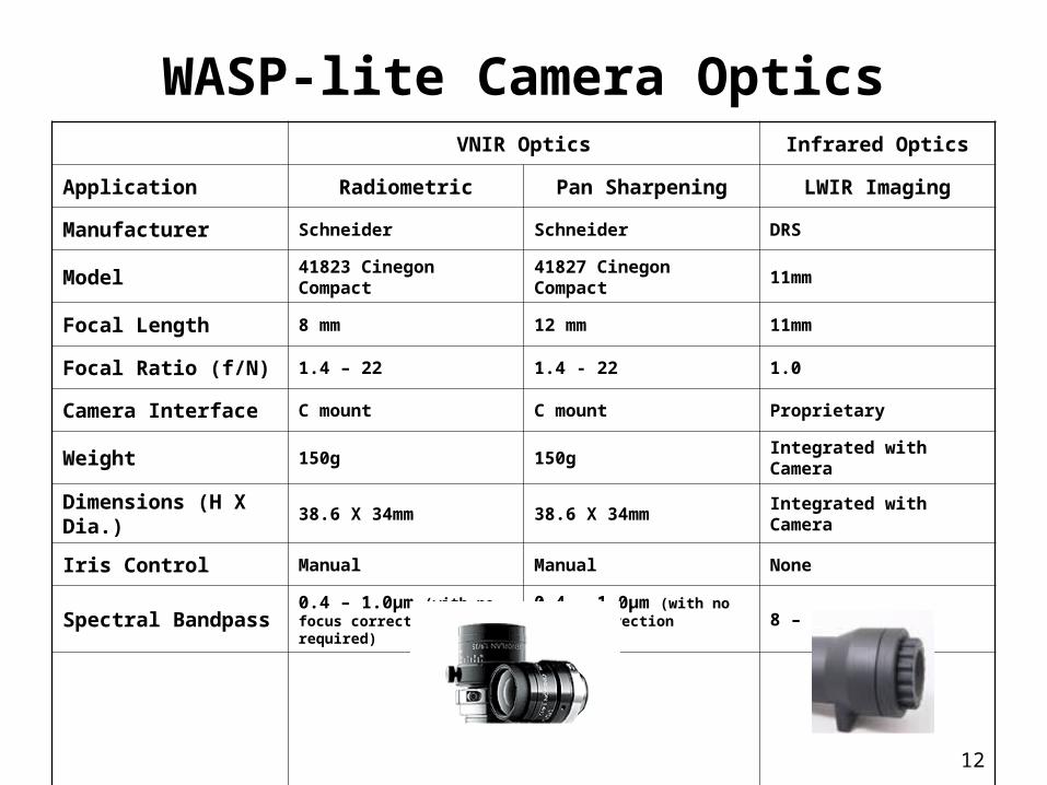
WASP-lite Camera OpticsVNIR Optics Infrared Optics
Application Radiometric Pan Sharpening LWIR Imaging
Manufacturer Schneider Schneider DRS
Model 41823 Cinegon Compact 41827 Cinegon Compact 11mm
Focal Length 8 mm 12 mm 11mm
Focal Ratio (f/N) 1.4 – 22 1.4 - 22 1.0
Camera Interface C mount C mount Proprietary
Weight 150g 150g Integrated with Camera
Dimensions (H X Dia.) 38.6 X 34mm 38.6 X 34mm Integrated with Camera
Iris Control Manual Manual None
Spectral Bandpass 0.4 – 1.0µm (with no focus correction required)
0.4 – 1.0µm (with no focus correction required)
8 – 12 µm

13
Detailed Design:
Electronics Rack Assembly
14
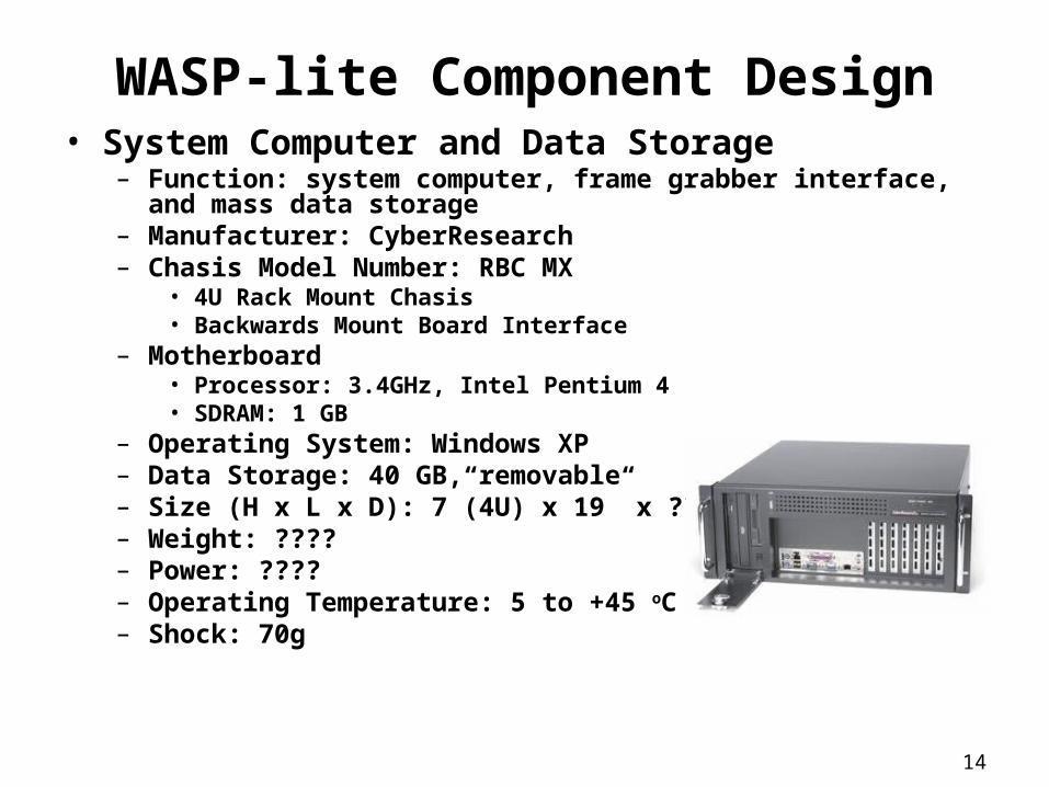
WASP-lite Component Design• System Computer and Data Storage
– Function: system computer, frame grabber interface, and mass data storage
– Manufacturer: CyberResearch– Chasis Model Number: RBC MX
• 4U Rack Mount Chasis• Backwards Mount Board Interface
– Motherboard• Processor: 3.4GHz, Intel Pentium 4• SDRAM: 1 GB
– Operating System: Windows XP– Data Storage: 40 GB, removable– Size (H x L x D): 7”(4U) x 19” x ??– Weight: ????– Power: ????– Operating Temperature: 5 to +45 oC– Shock: 70g
15
Software Design Approach
• COTS Windows XP OS• SDKs from Coreco (MS + Pan cameras) & NI (LWIR
camera) to talk to camera & timer hardware• Visual C++ to talk to SDK’s, integrate system, compile
information, and organize for easy post processing• Custom written module to capture and process
information from the CMIGITS Nav system (async RS-232 serial)
• Multi-Threaded design for speed• Flexible to allow ease of adding/subtracting cameras
from the system• Easy to use GUI targeted for touch panel operation in a
very confined cockpit of the aircraft
16
Power Supply Subsystem
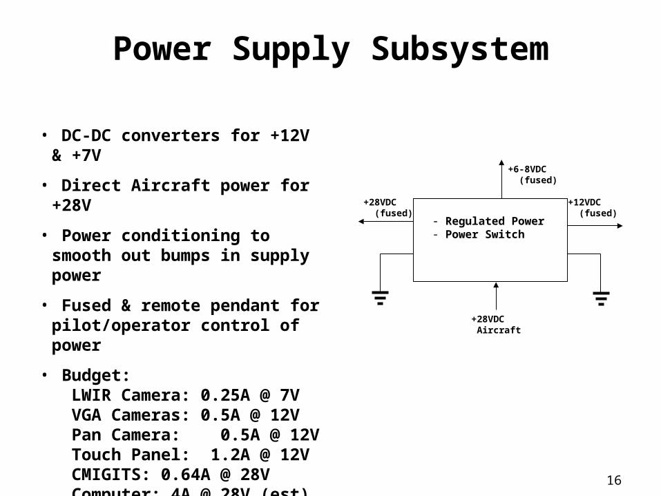
• DC-DC converters for +12V & +7V
• Direct Aircraft power for +28V
• Power conditioning to smooth out bumps in supply power
• Fused & remote pendant for pilot/operator control of power
• Budget: LWIR Camera: 0.25A @ 7V VGA Cameras: 0.5A @ 12V Pan Camera: 0.5A @ 12V Touch Panel: 1.2A @ 12V CMIGITS: 0.64A @ 28V Computer: 4A @ 28V (est)
- Regulated Power - Power Switch
+28VDC (fused)
+12VDC (fused)
+28VDC Aircraft
+6-8VDC (fused)
17
Timing Subsystem
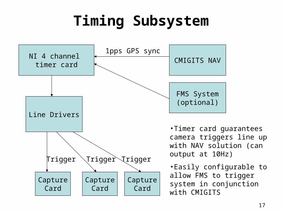
NI 4 channel timer card
CMIGITS NAV1pps GPS sync
FMS System(optional)
Line Drivers
CaptureCard
CaptureCard
CaptureCard
Trigger Trigger Trigger
•Timer card guarantees camera triggers line up with NAV solution (can output at 10Hz)
•Easily configurable to allow FMS to trigger system in conjunction with CMIGITS
18
19” Electronics Rack Enclosure
19
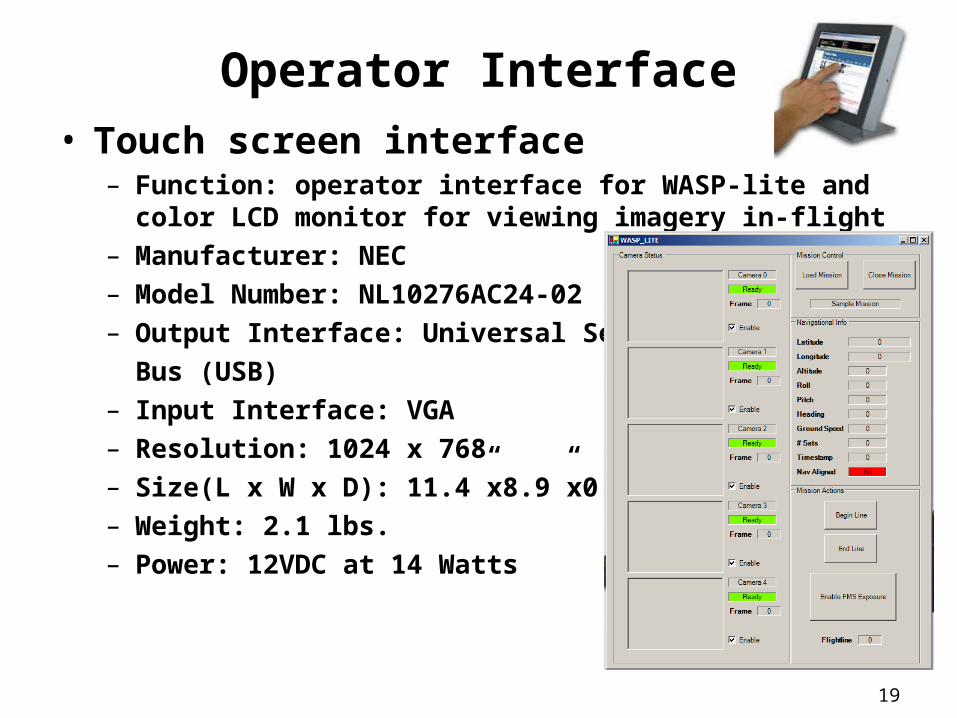
Operator Interface• Touch screen interface
– Function: operator interface for WASP-lite and color LCD monitor for viewing imagery in-flight
– Manufacturer: NEC– Model Number: NL10276AC24-02– Output Interface: Universal Serial
Bus (USB)– Input Interface: VGA– Resolution: 1024 x 768– Size(L x W x D): 11.4”x8.9”x0.7”– Weight: 2.1 lbs.– Power: 12VDC at 14 Watts

20
Mechanical Packaging, Integration Approach, and Aircraft Interface
21
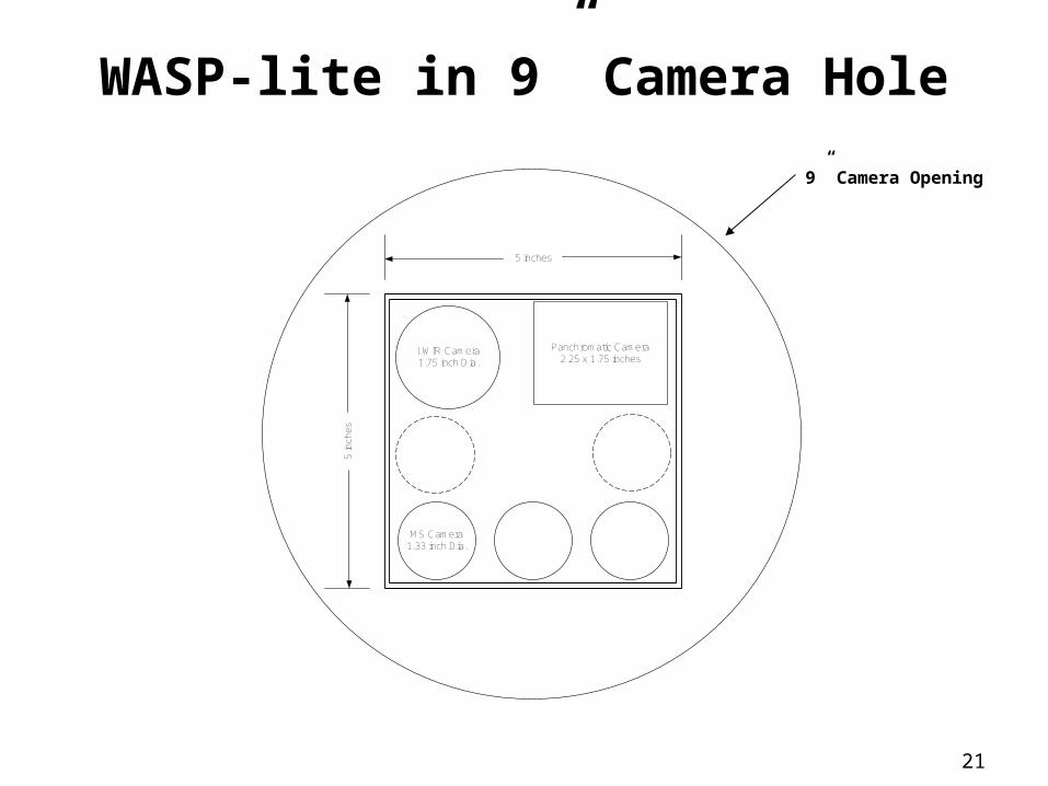
WASP-lite in 9” Camera Hole
9” Camera Opening
MS Camera1.33 inch Dia.
5 inches
5 in
ches
LWIR Camera1.75 inch Dia.
Panchromatic Camera2.25 x 1.75 inches
22
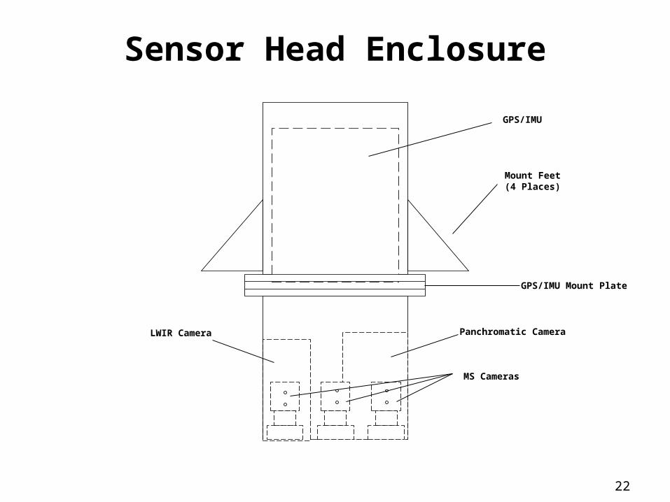
Sensor Head Enclosure
Mount Feet(4 Places)
MS Cameras
Panchromatic CameraLWIR Camera
GPS/IMU
GPS/IMU Mount Plate
23
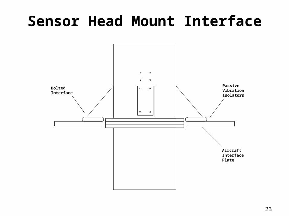
Sensor Head Mount Interface
PassiveVibrationIsolators
AircraftInterfacePlate
BoltedInterface
24
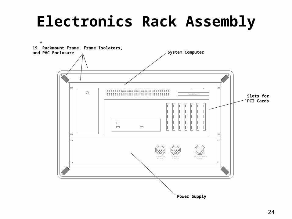
Electronics Rack Assembly
CyberResearch
Aircraft Power In+ 28VDC
Power Out+ 28VDC
Power Out+ 12VDC
System Computer
Power Supply
Slots forPCI Cards
19” Rackmount Frame, Frame Isolators,and PVC Enclosure
25
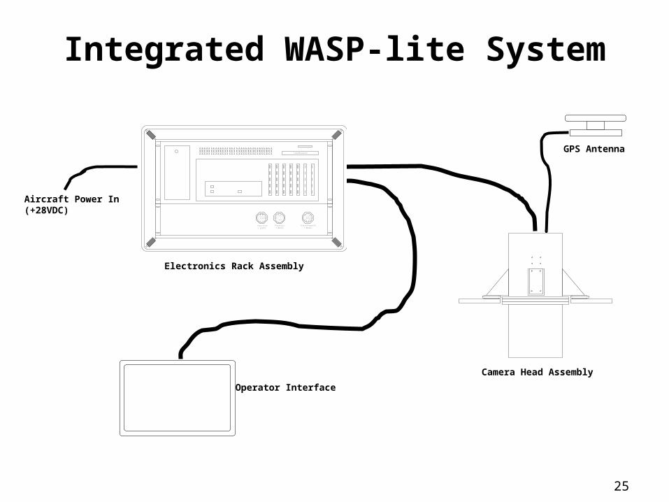
Integrated WASP-lite System
GPS Antenna
Camera Head Assembly
Operator Interface
Electronics Rack Assembly
CyberResearch
Aircraft Power In+ 28VDC
Power Out+ 28VDC
Power Out+ 12VDC
Aircraft Power In(+28VDC)
26
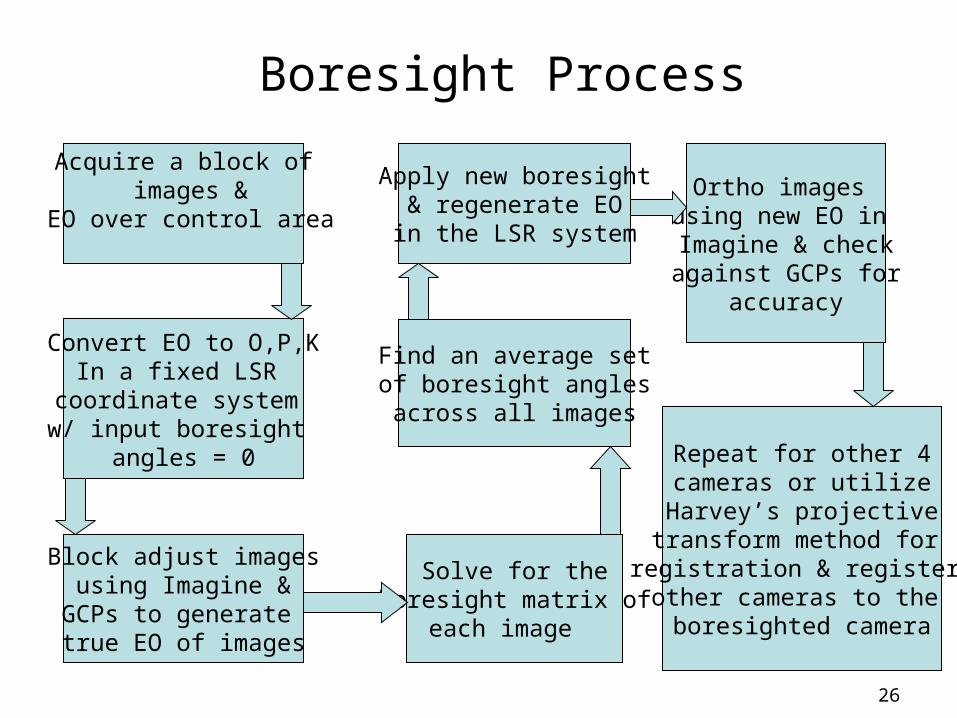
Boresight Process
Acquire a block of images &
EO over control area
Convert EO to O,P,KIn a fixed LSR
coordinate system w/ input boresight
angles = 0
Block adjust imagesusing Imagine &
GCPs to generate true EO of images
Solve for the boresight matrix of
each image
Find an average setof boresight anglesacross all images
Apply new boresight& regenerate EO
in the LSR system
Ortho images using new EO in Imagine & checkagainst GCPs for
accuracy
Repeat for other 4cameras or utilize
Harvey’s projectivetransform method for registration & register other cameras to the boresighted camera

27
System Functional Analysis
28
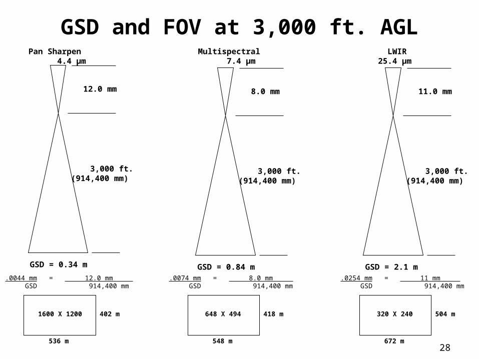
GSD and FOV at 3,000 ft. AGL
12.0 mm
Pan Sharpen 4.4 µm
3,000 ft.(914,400 mm)
GSD = 0.34 m
8.0 mm
Multispectral 7.4 µm
3,000 ft.(914,400 mm)
GSD = 0.84 m
11.0 mm
LWIR25.4 µm
3,000 ft.(914,400 mm)
GSD = 2.1 m.0044 mm = 12.0 mm GSD 914,400 mm
1600 X 1200
536 m
402 m
.0074 mm = 8.0 mm GSD 914,400 mm
648 X 494
548 m
418 m
.0254 mm = 11 mm GSD 914,400 mm
320 X 240
672 m
504 m
29
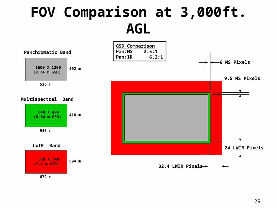
FOV Comparison at 3,000ft. AGL
1600 X 1200(0.34 m GSD)
536 m
402 m
648 X 494(0.84 m GSD)
548 m
418 m
320 X 240(2.1 m GSD)
672 m
504 m
Panchromatic Band
Multispectral Band
LWIR Band 24 LWIR Pixels
9.5 MS Pixels
6 MS Pixels
32.4 LWIR Pixels
GSD ComparisonPan:MS 2.5:1Pan:IR 6.2:1
30
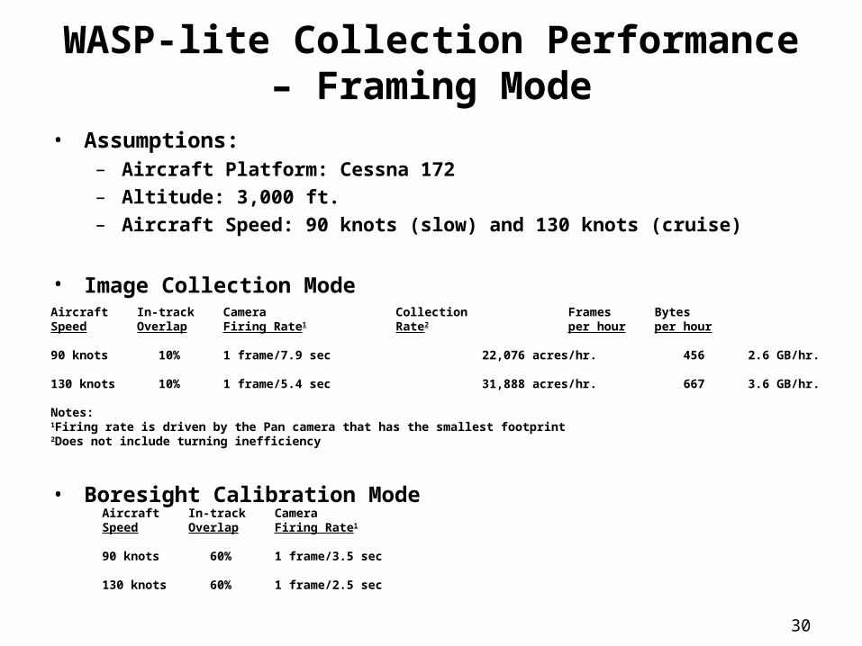
WASP-lite Collection Performance – Framing Mode
• Assumptions:– Aircraft Platform: Cessna 172– Altitude: 3,000 ft.– Aircraft Speed: 90 knots (slow) and 130 knots (cruise)
• Image Collection Mode
• Boresight Calibration ModeAircraft In-track CameraSpeed Overlap Firing Rate1
90 knots 60% 1 frame/3.5 sec
130 knots 60% 1 frame/2.5 sec
Aircraft In-track Camera Collection Frames BytesSpeed Overlap Firing Rate1 Rate2 per hour per hour
90 knots 10% 1 frame/7.9 sec 22,076 acres/hr. 456 2.6 GB/hr.
130 knots 10% 1 frame/5.4 sec 31,888 acres/hr. 667 3.6 GB/hr.
Notes:1Firing rate is driven by the Pan camera that has the smallest footprint2Does not include turning inefficiency
31
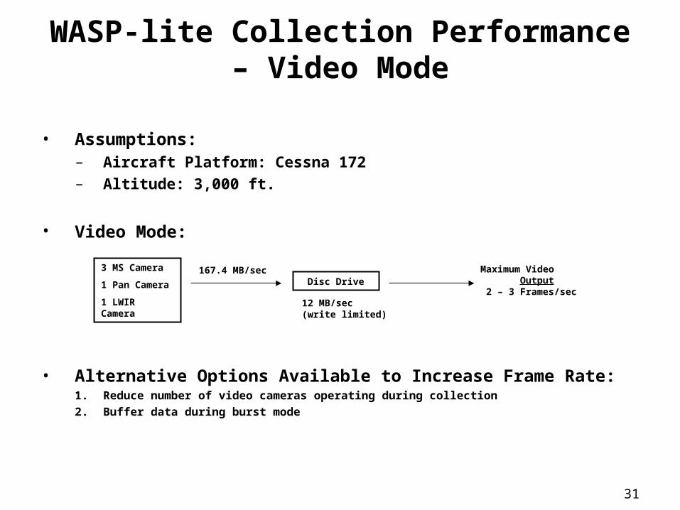
WASP-lite Collection Performance – Video Mode
• Assumptions:– Aircraft Platform: Cessna 172– Altitude: 3,000 ft.
• Video Mode:
• Alternative Options Available to Increase Frame Rate:1. Reduce number of video cameras operating during collection
2. Buffer data during burst mode
3 MS Camera
1 Pan Camera
1 LWIR Camera
Disc Drive Maximum Video Output 2 – 3 Frames/sec
167.4 MB/sec
12 MB/sec(write limited)

32
Application Experiments
33
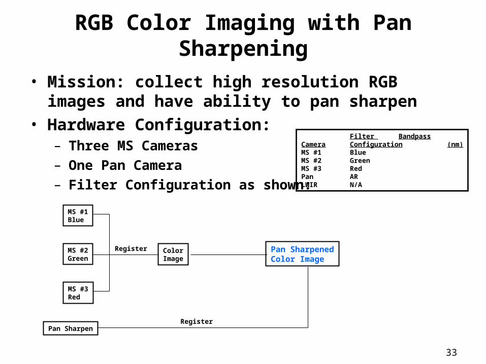
RGB Color Imaging with Pan Sharpening
• Mission: collect high resolution RGB images and have ability to pan sharpen
• Hardware Configuration:– Three MS Cameras– One Pan Camera– Filter Configuration as shown:
Filter BandpassCamera Configuration (nm)MS #1 BlueMS #2 GreenMS #3 RedPan ARLWIR N/A
MS #1Blue
MS #2Green
MS #3Red
Pan Sharpen
Pan SharpenedColor Image
ColorImage
Register
Register
34
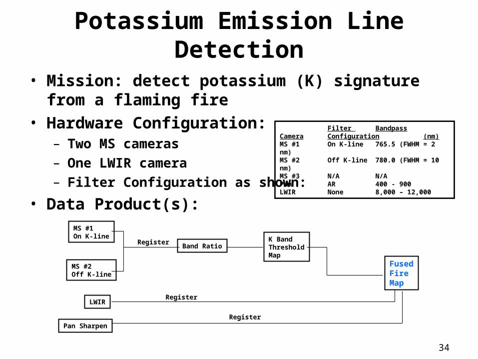
Potassium Emission Line Detection
• Mission: detect potassium (K) signature from a flaming fire
• Hardware Configuration:– Two MS cameras– One LWIR camera– Filter Configuration as shown:
• Data Product(s):
Filter BandpassCamera Configuration (nm)MS #1 On K-line 765.5 (FWHM = 2 nm)MS #2 Off K-line 780.0 (FWHM = 10 nm)MS #3 N/A N/APan AR 400 - 900LWIR None 8,000 – 12,000
MS #1On K-line
MS #2Off K-line
Pan Sharpen
LWIR
Band RatioRegister
FusedFireMap
Register
K BandThresholdMap
Register
35
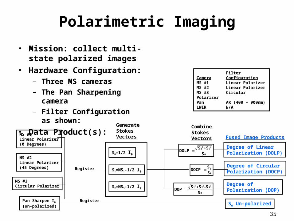
Polarimetric Imaging
• Mission: collect multi-state polarized images
• Hardware Configuration:– Three MS cameras
– The Pan Sharpening camera
– Filter Configuration as shown:
• Data Product(s):
Filter Camera ConfigurationMS #1 Linear PolarizerMS #2 Linear PolarizerMS #3 Circular PolarizerPan AR (400 – 900nm)LWIR N/A
MS #1Linear Polarizer(0 Degrees)
MS #2Linear Polarizer(45 Degrees)
MS #3Circular Polarizer
Pan Sharpen I0(un-polarized)
Fused Image Products
S0 Un-polarized
Degree of Linear Polarization (DOLP)
Degree of CircularPolarization (DOCP)
Degree ofPolarization (DOP)
Register
CombineStokesVectors
GenerateStokesVectors
S0=1/2 I0
S1=MS1-1/2 I0
S2=MS3-1/2 I0
0
21
S
SSDOLP
22
0
3
S
SDOCP
0
321
S
SSSDOP
222
Register
36
WASP-lite Programmatics
37
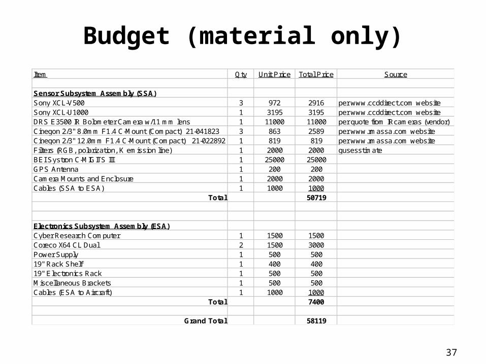
Budget (material only)Item Qty Unit Price Total Price Source
Sensor Subsystem Assembly (SSA)Sony XCL-V500 3 972 2916 per www.ccddirect.com websiteSony XCL-U1000 1 3195 3195 per www.ccddirect.com websiteDRS E3500 IR Bolometer Camera w/11 mm lens 1 11000 11000 per quote from IRcameras (vendor)Cinegon 2/3" 8.0mm F1.4 C-Mount (Compact) 21-041823 3 863 2589 per www.rmassa.com websiteCinegon 2/3" 12.0mm F1.4 C-Mount (Compact) 21-022892 1 819 819 per www.rmassa.com websiteFilters (RGB, polarization, K emission line) 1 2000 2000 gusesstimateBEI Systron C-MIGITS III 1 25000 25000GPS Antenna 1 200 200Camera Mounts and Enclosure 1 2000 2000Cables (SSA to ESA) 1 1000 1000
Total 50719
Electronics Subsystem Assembly (ESA)Cyber Research Computer 1 1500 1500Coreco X64 CL Dual 2 1500 3000Power Supply 1 500 50019" Rack Shelf 1 400 40019" Electronics Rack 1 500 500Miscellaneous Brackets 1 500 500Cables (ESA to Aircraft) 1 1000 1000
Total 7400
Grand Total 58119

38
Schedule
18 - 22 25 - 29 2 - 6 9 - 13 16 - 20 23 - 27 30 - 3 6 - 10 13 - 17 20 - 24 27 - 1 4 - 8 11 - 15 18 - 22 25 - 29
Procurement
Detailed Design
Fabrication
Integration
Final Test and Evaluation
First Flight
April May June July