Embed Size (px)
Citation preview
1
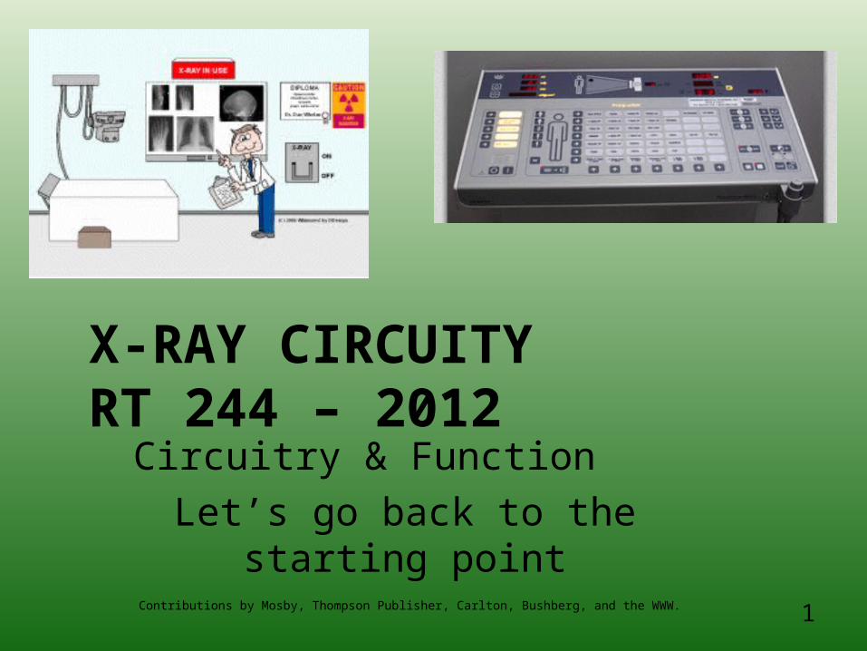
X-RAY CIRCUITYRT 244 – 2012
Circuitry & Function
Let’s go back to the starting point
Contributions by Mosby, Thompson Publisher, Carlton, Bushberg, and the WWW.
2
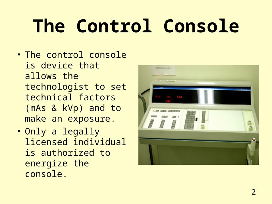
The Control Console
• The control console is device that allows the technologist to set technical factors (mAs & kVp) and to make an exposure.
• Only a legally licensed individual is authorized to energize the console.
3
Operating Console has meters to measure
• kVp, mA, & exposure time
• Modern units only display mAs
• Units with ACE’s will have a separate meter for mAs
4
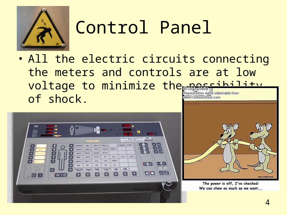
Control Panel
• All the electric circuits connecting the meters and controls are at low voltage to minimize the possibility of shock.
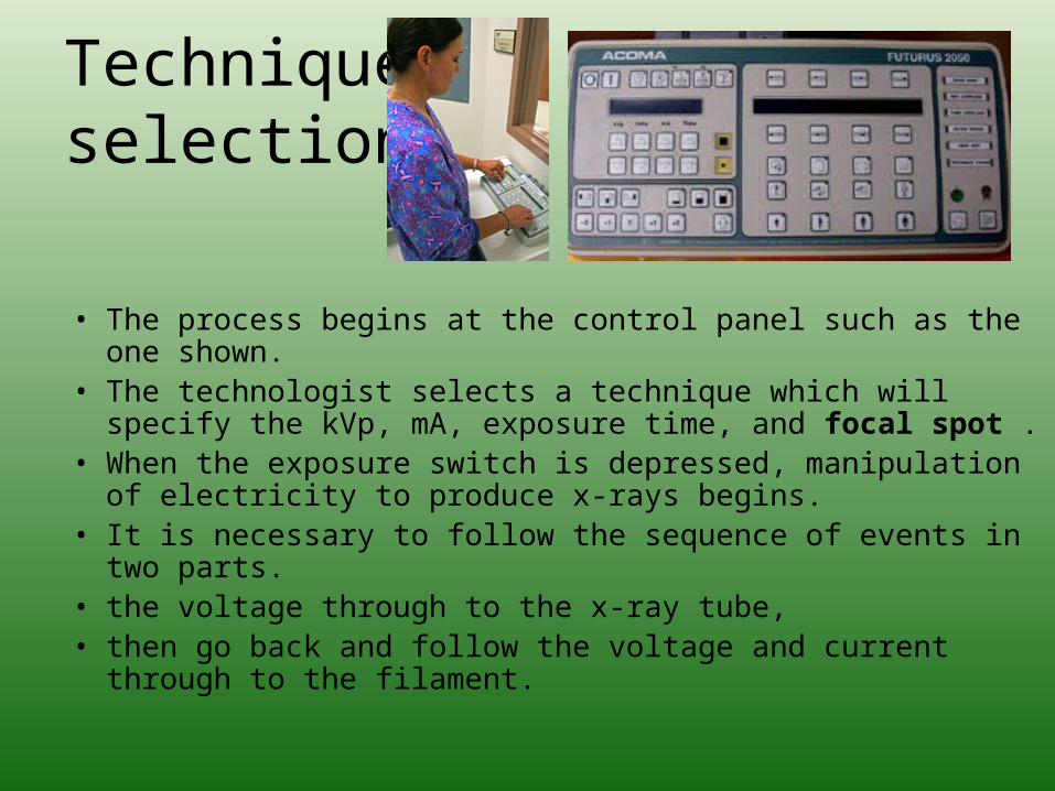
Technique selection
• The process begins at the control panel such as the one shown.
• The technologist selects a technique which will specify the kVp, mA, exposure time, and focal spot .
• When the exposure switch is depressed, manipulation of electricity to produce x-rays begins.
• It is necessary to follow the sequence of events in two parts. • the voltage through to the x-ray tube, • then go back and follow the voltage and current through to
the filament.
6
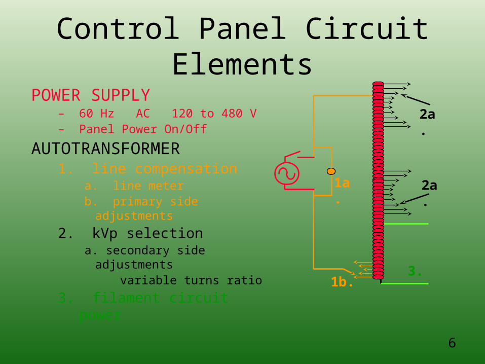
Control Panel Circuit Elements
POWER SUPPLY– 60 Hz AC 120 to 480 V– Panel Power On/Off
AUTOTRANSFORMER1. line compensation
a. line meterb. primary side adjustments
2. kVp selectiona. secondary side
adjustments variable turns ratio
3. filament circuit power
1a.
1b.
2a.
2a.
3.
7
Operating Console Controls:
• Line Compensation
• Quantity = # of x-rays– Milliroentges (mR) or (mR/mAs)
• Quality = the pentrability– Kilovolts peak (kVp) or HVL
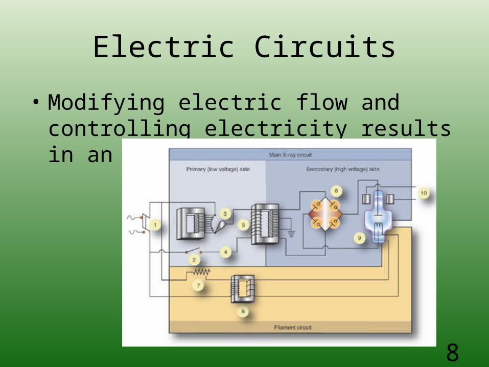
Electric Circuits
• Modifying electric flow and controlling electricity results in an electric circuit.
8
9
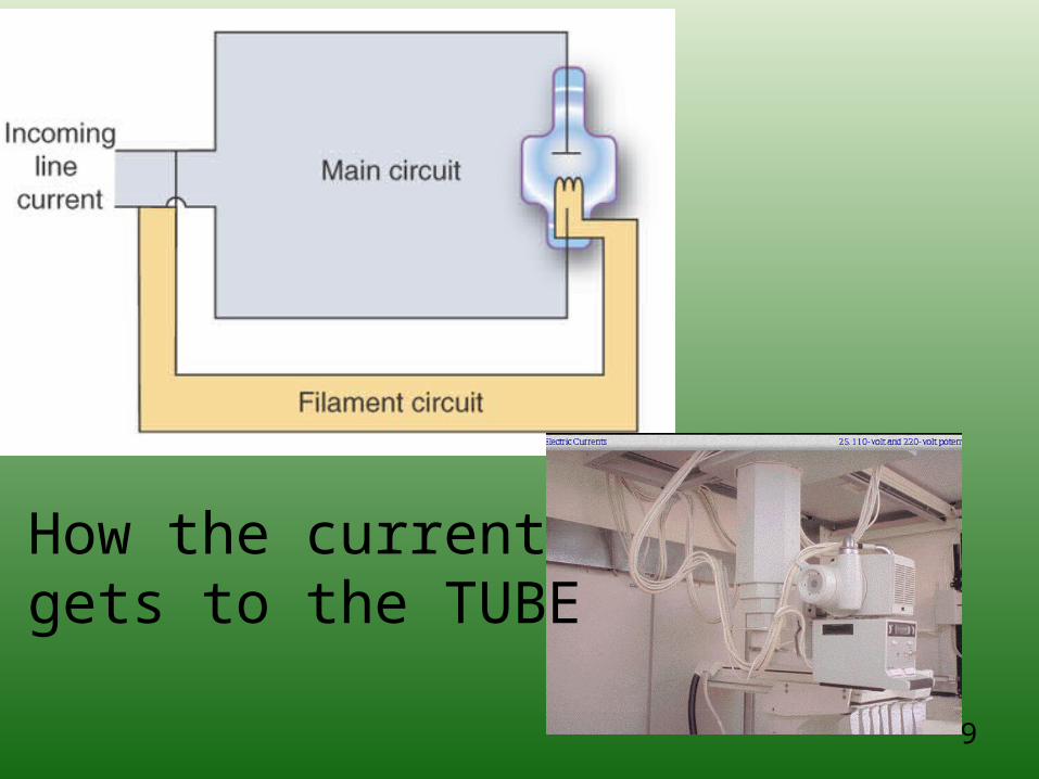
How the current gets to the TUBE
10
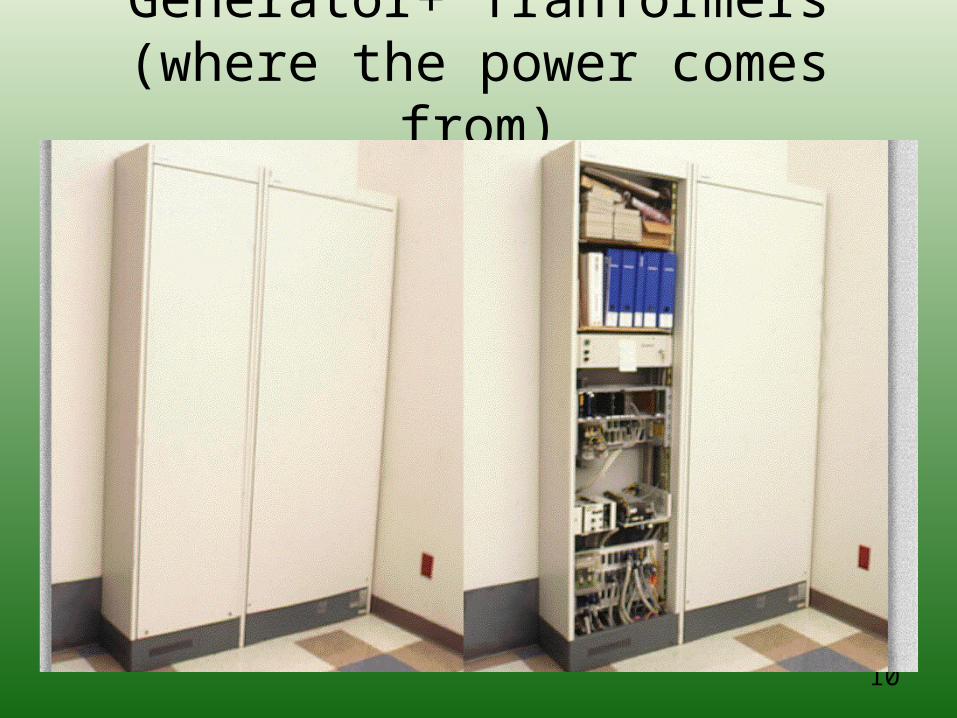
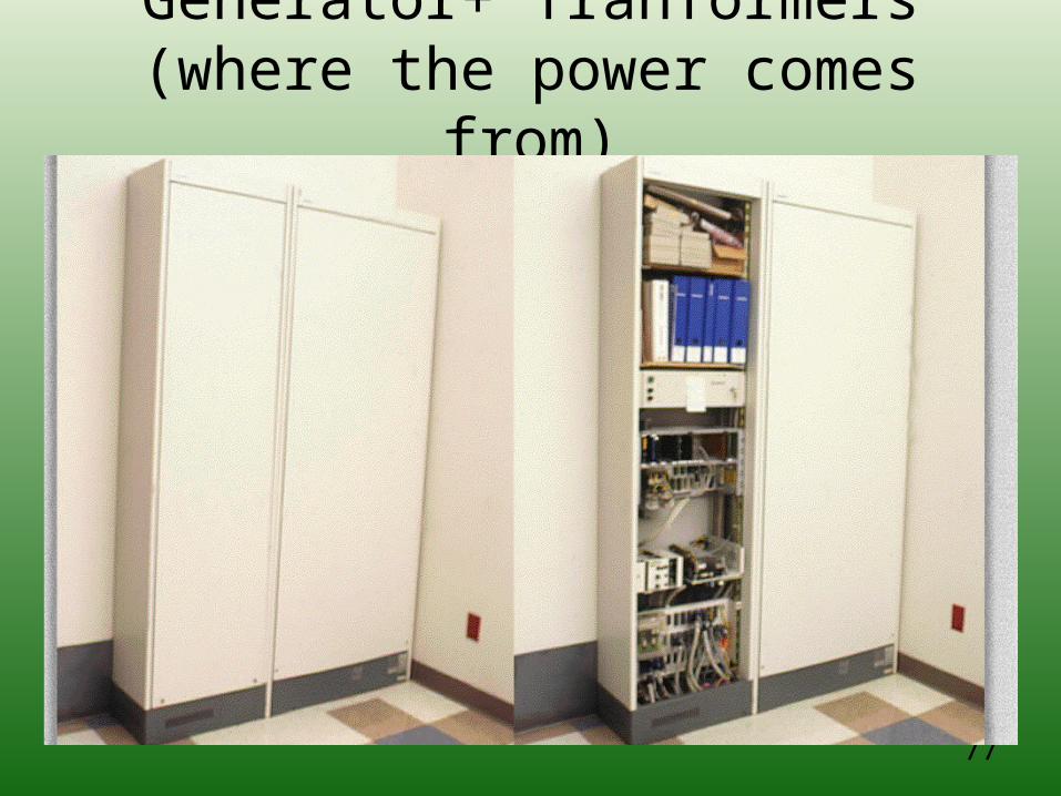
Generator+ Tranformers(where the power comes from)
11
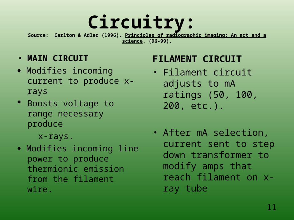
Circuitry: Source: Carlton & Adler (1996). Principles of radiographic imaging: An art and a science. (96-99).
• MAIN CIRCUIT
Modifies incoming current to produce x-rays
Boosts voltage to range necessary produce
x-rays.
Modifies incoming line power to produce thermionic emission from the filament wire.
FILAMENT CIRCUIT• Filament circuit adjusts to
mA ratings (50, 100, 200, etc.).
• After mA selection, current sent to step down transformer to modify amps that reach filament on x-ray tube
12
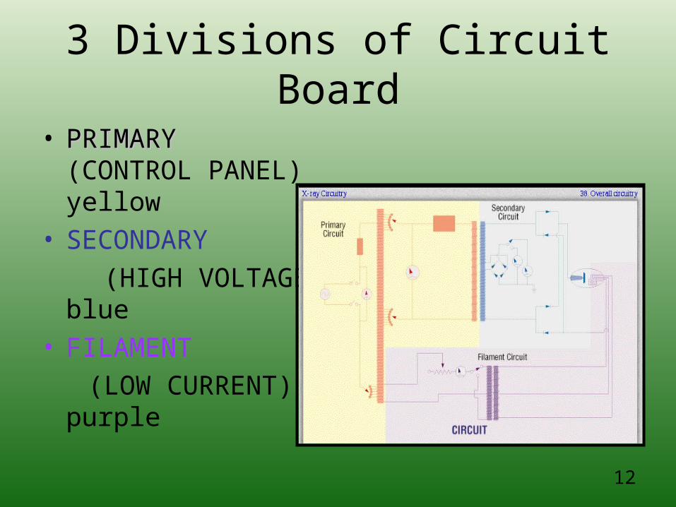
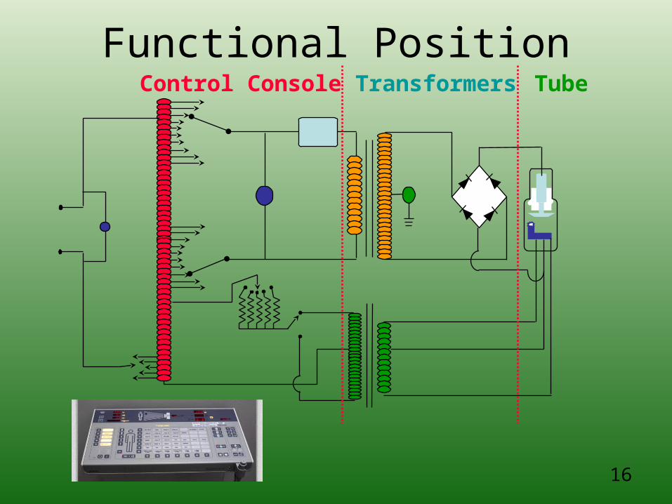
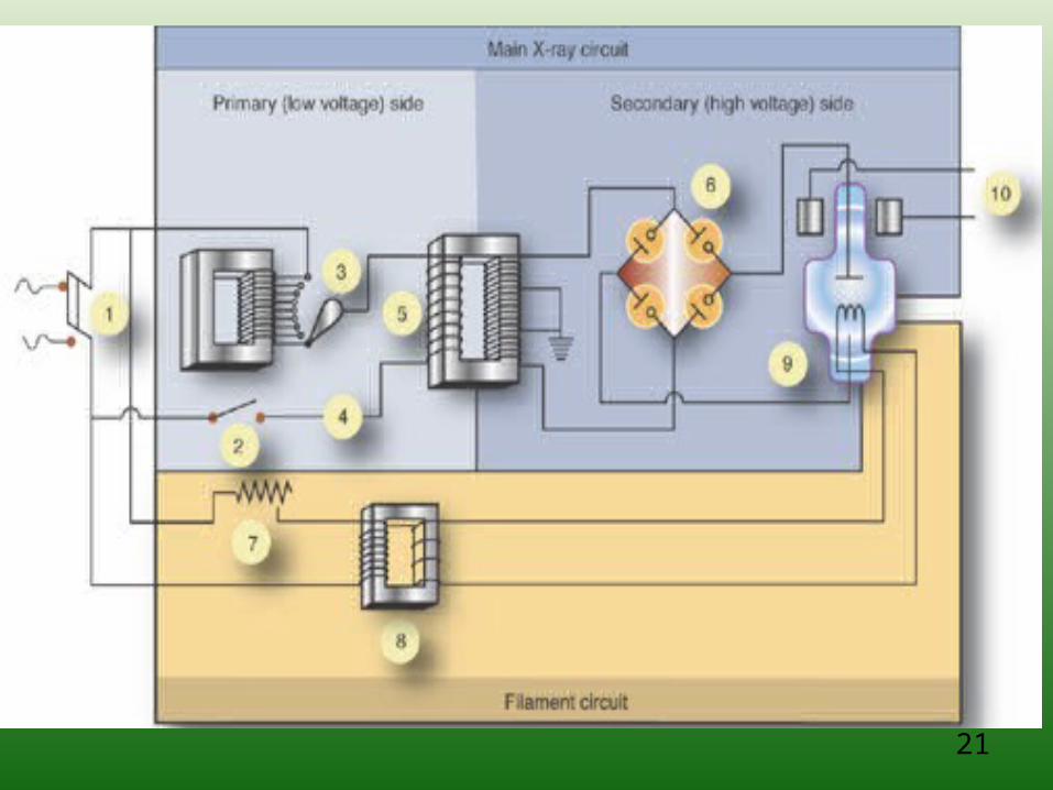
3 Divisions of Circuit Board
• PRIMARYPRIMARY (CONTROL PANEL) yellow
• SECONDARY
(HIGH VOLTAGE) blue
• FILAMENT
(LOW CURRENT) purple
13
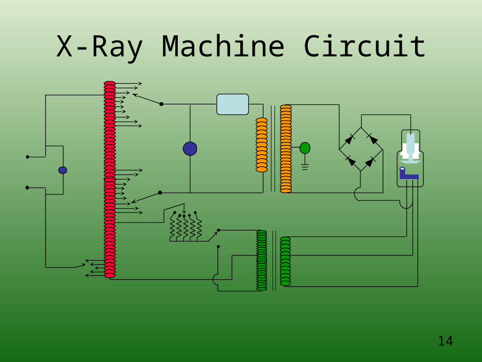
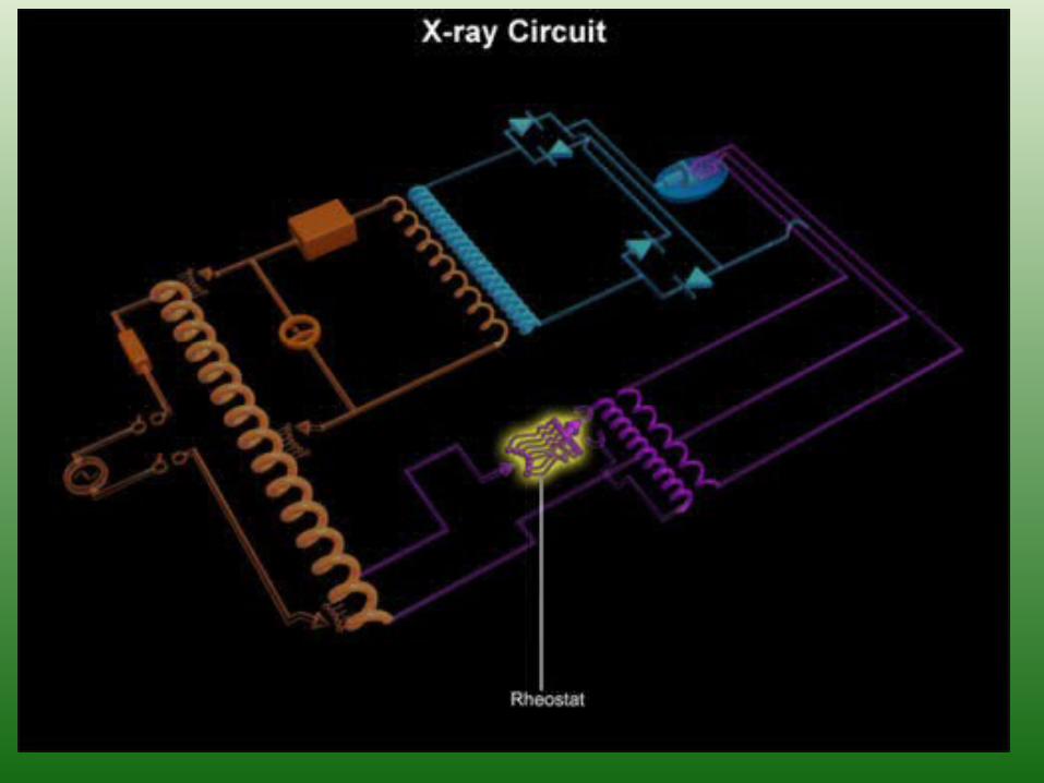
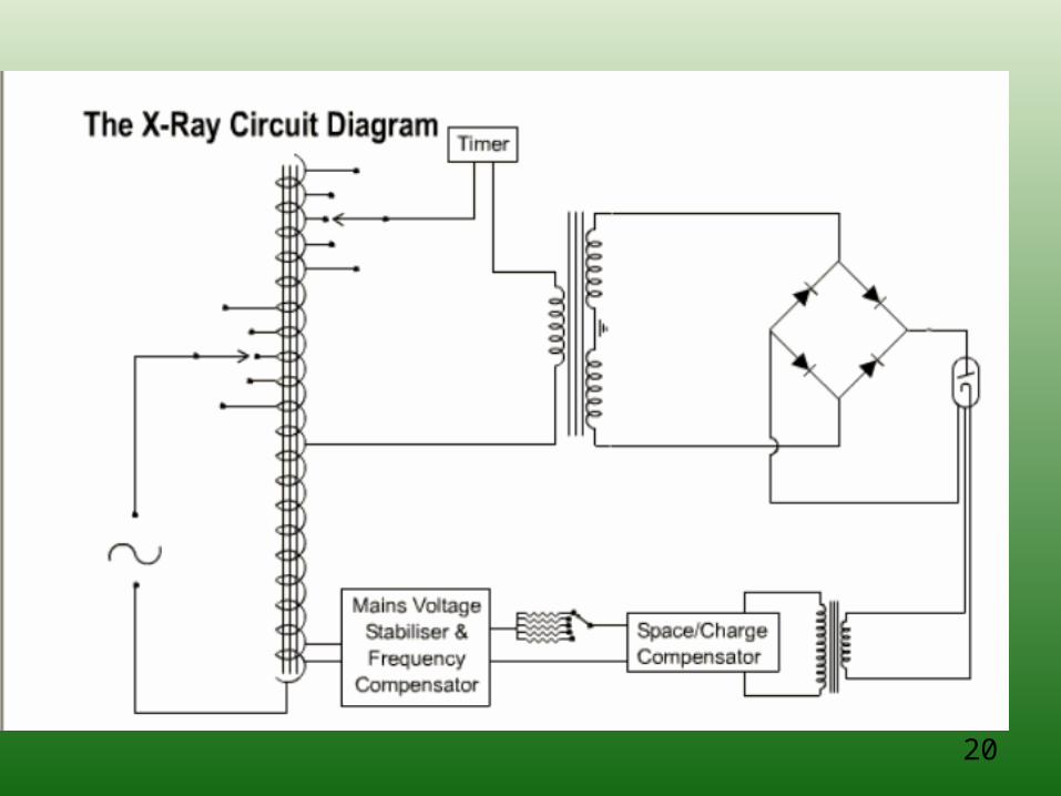
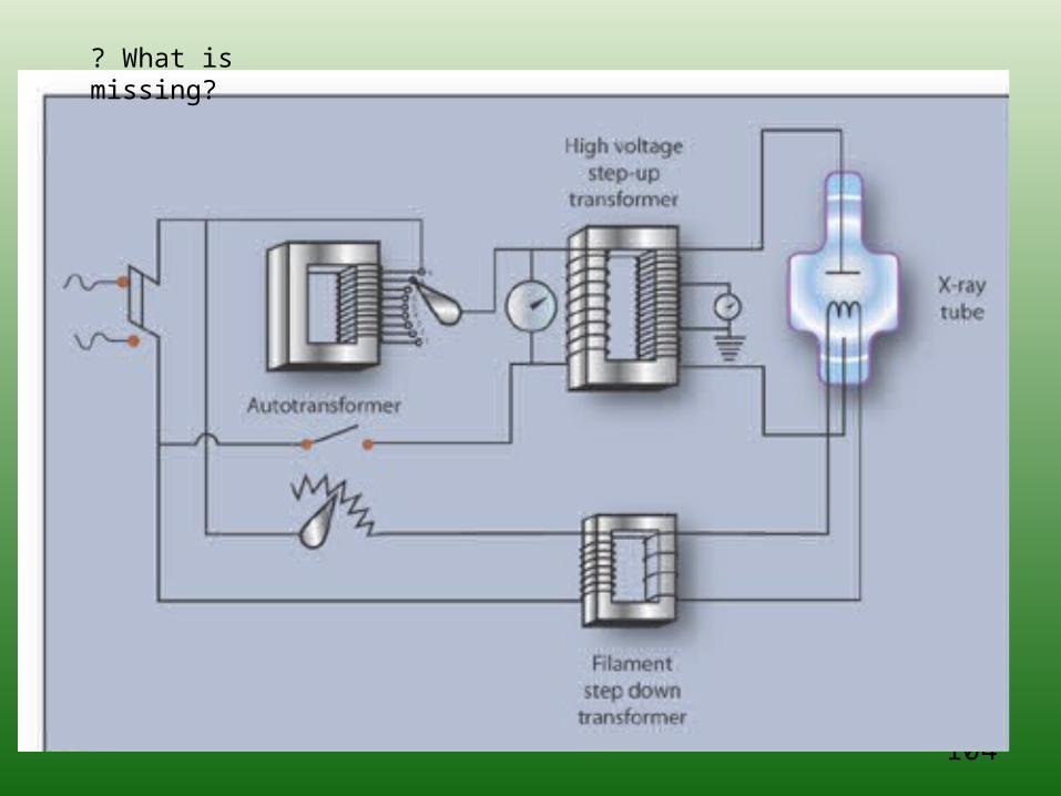
X-Ray Machine Circuit
14
16
Functional PositionControl Console Transformers Tube
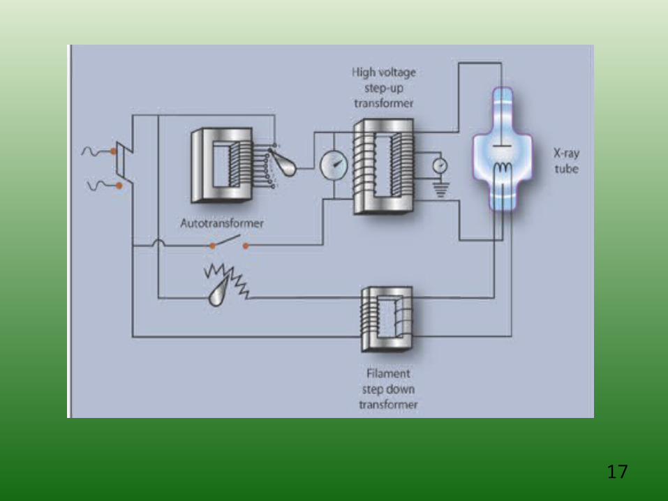
17
18© UW and Brent K. Stewart PhD, DABMP© UW and Brent K. Stewart PhD, DABMP
1818
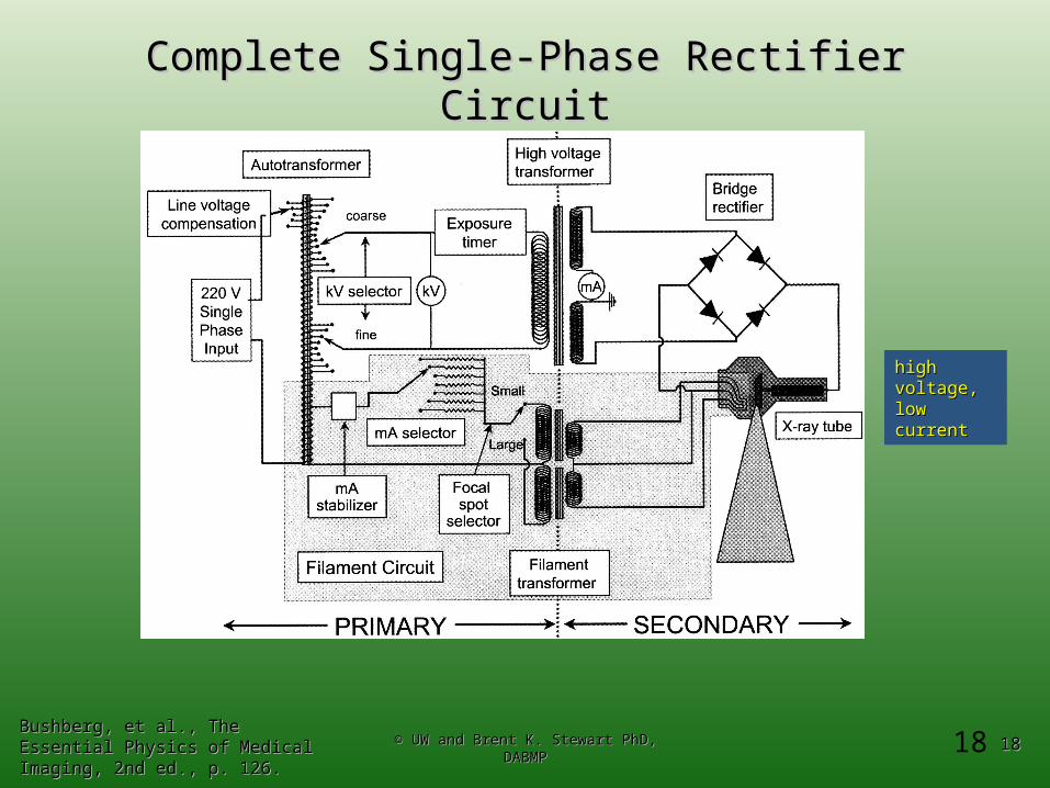
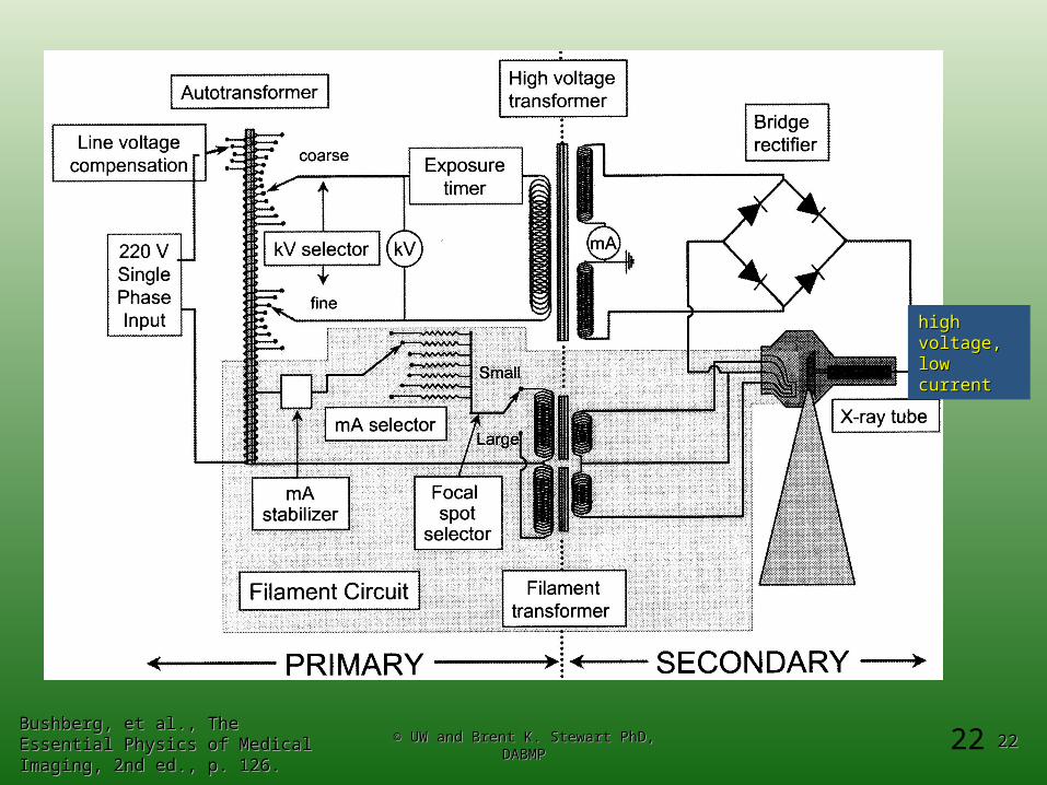
Complete Single-Phase Rectifier CircuitComplete Single-Phase Rectifier Circuit
Bushberg, et al., The Essential Physics Bushberg, et al., The Essential Physics of Medical Imaging, 2nd ed., p. 126.of Medical Imaging, 2nd ed., p. 126.
high voltage, high voltage, low currentlow current
19
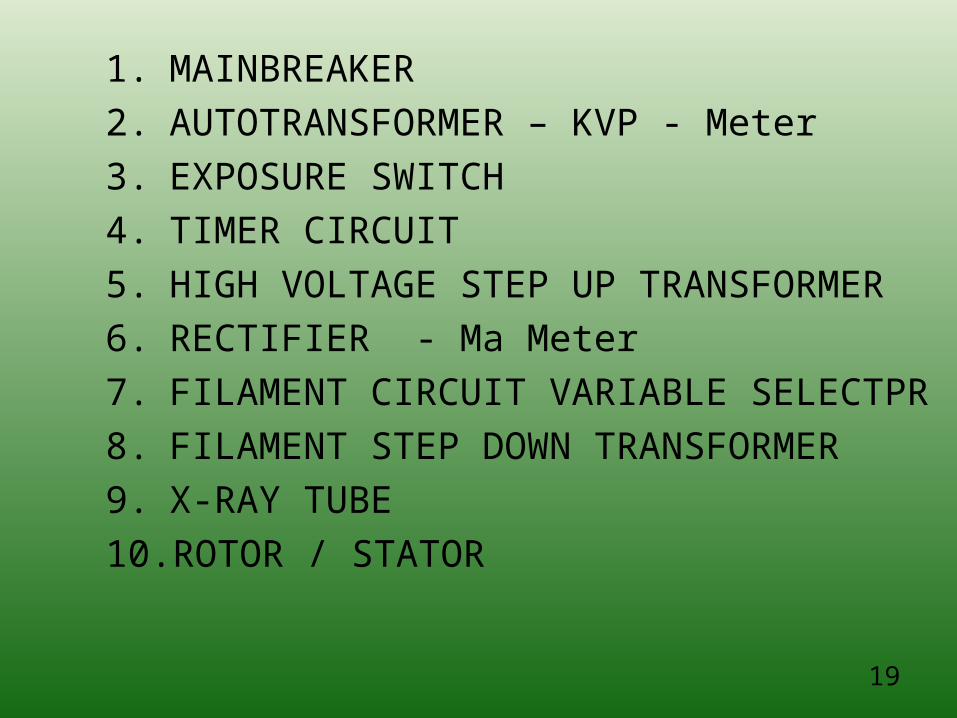
1. MAINBREAKER
2. AUTOTRANSFORMER – KVP - Meter
3. EXPOSURE SWITCH
4. TIMER CIRCUIT
5. HIGH VOLTAGE STEP UP TRANSFORMER
6. RECTIFIER - Ma Meter
7. FILAMENT CIRCUIT VARIABLE SELECTPR
8. FILAMENT STEP DOWN TRANSFORMER
9. X-RAY TUBE
10. ROTOR / STATOR
20
21
22© UW and Brent K. Stewart PhD, DABMP© UW and Brent K. Stewart PhD, DABMP
2222 Bushberg, et al., The Essential Physics Bushberg, et al., The Essential Physics of Medical Imaging, 2nd ed., p. 126.of Medical Imaging, 2nd ed., p. 126.
high voltage, high voltage, low currentlow current
23
24
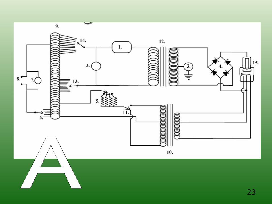
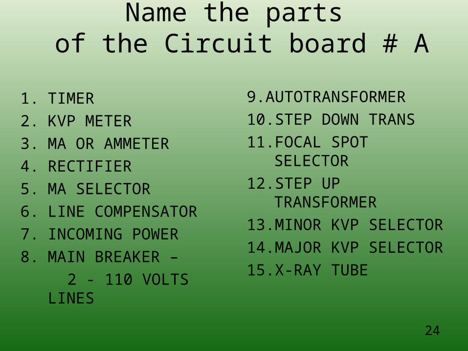
Name the parts of the Circuit board # A
1. TIMER
2. KVP METER
3. MA OR AMMETER
4. RECTIFIER
5. MA SELECTOR
6. LINE COMPENSATOR
7. INCOMING POWER
8. MAIN BREAKER –
2 - 110 VOLTS LINES
9.AUTOTRANSFORMER
10. STEP DOWN TRANS
11. FOCAL SPOT SELECTOR
12. STEP UP TRANSFORMER
13. MINOR KVP SELECTOR
14. MAJOR KVP SELECTOR
15. X-RAY TUBE
25
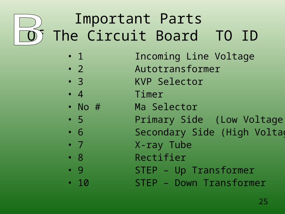
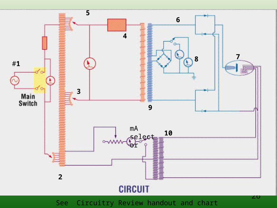
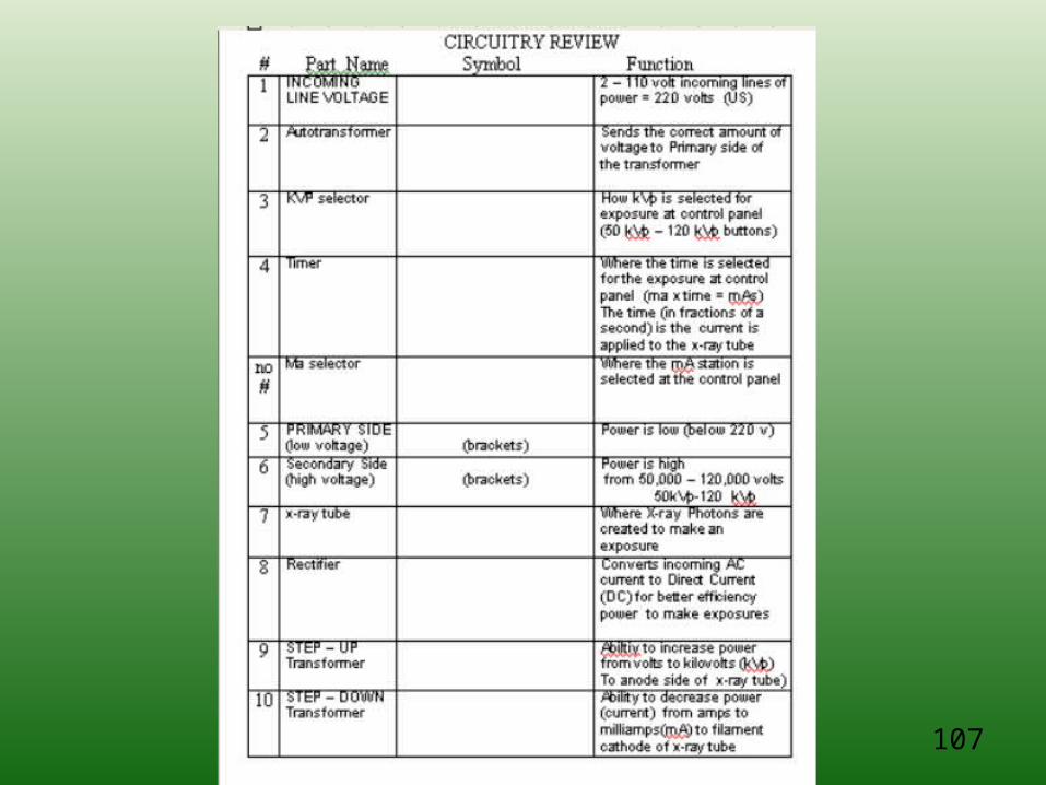
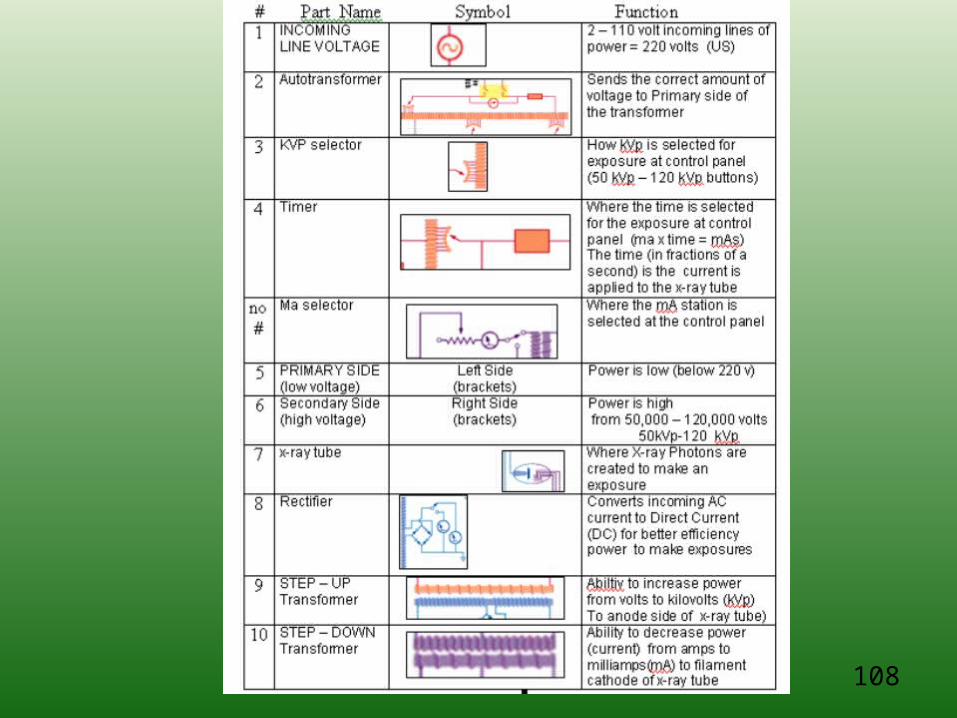
Important Parts Of The Circuit Board TO ID
• 1 Incoming Line Voltage• 2 Autotransformer• 3 KVP Selector• 4 Timer• No # Ma Selector• 5 Primary Side (Low Voltage)• 6 Secondary Side (High Voltage)• 7 X-ray Tube• 8 Rectifier• 9 STEP – Up Transformer• 10 STEP – Down Transformer
26
#1
2
3
4
mA selector
56
78
9
10
See Circuitry Review handout and chart for numbers
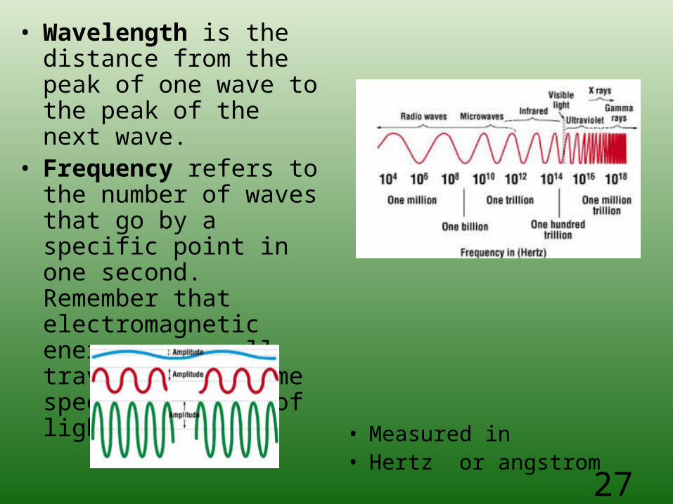
• Wavelength is the distance from the peak of one wave to the peak of the next wave.
• Frequency refers to the number of waves that go by a specific point in one second. Remember that electromagnetic energy waves all travel at the same speed—the speed of light
• Measured in • Hertz or angstrom
27
28
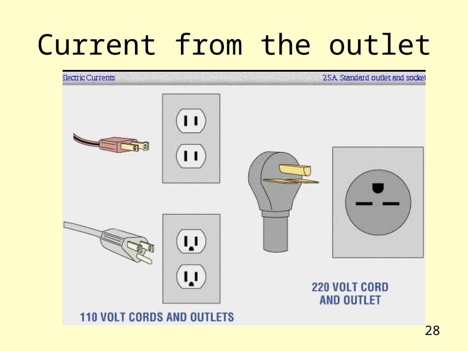
Current from the outlet
29
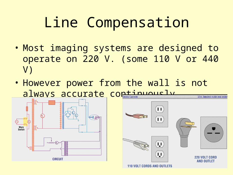
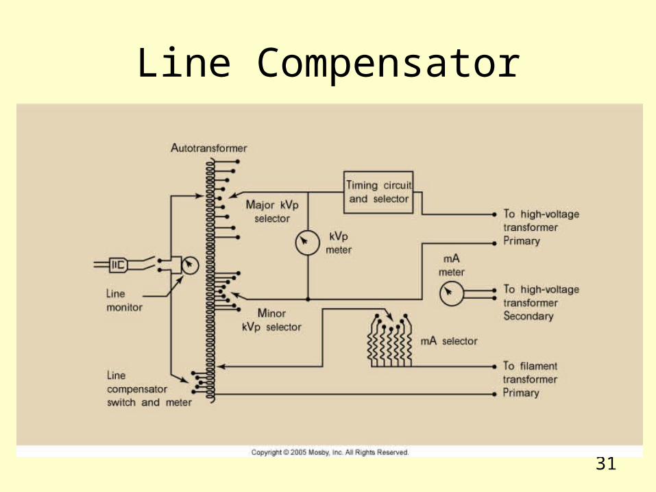
Line Compensation
• Most imaging systems are designed to operate on 220 V. (some 110 V or 440 V)
• However power from the wall is not always accurate continuously
30
Line Compensation
• Wired to the autotransformer is the line compensator
• Designed to maintain the accurate voltage required for consistent production of high-quality images
• Today’s line compensators are automatic and are not displayed on the control panel
31
Line Compensator
32
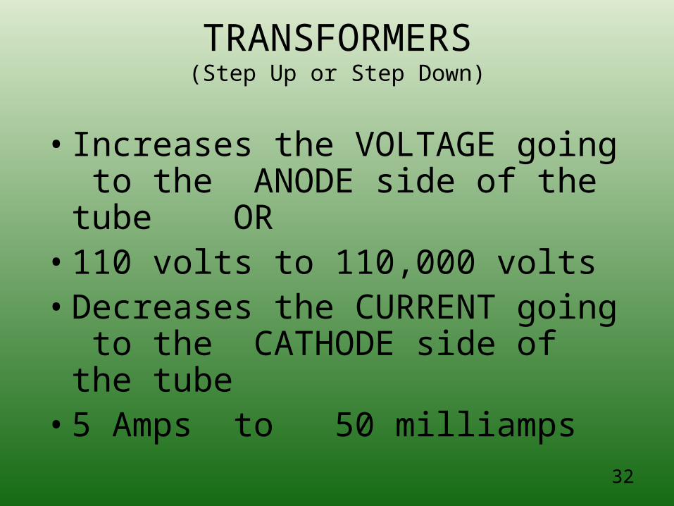
TRANSFORMERS(Step Up or Step Down)
• Increases the VOLTAGE going to the ANODE side of the tube OR
• 110 volts to 110,000 volts• Decreases the CURRENT going to
the CATHODE side of the tube• 5 Amps to 50 milliamps
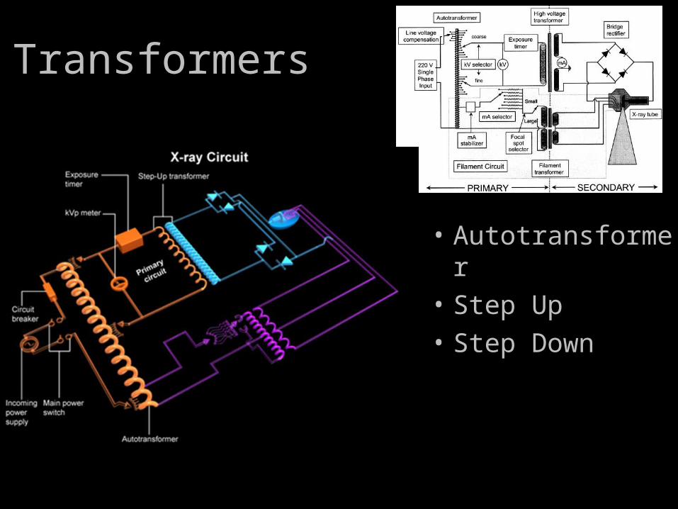
Transformers
• Autotransformer
• Step Up
• Step Down
34
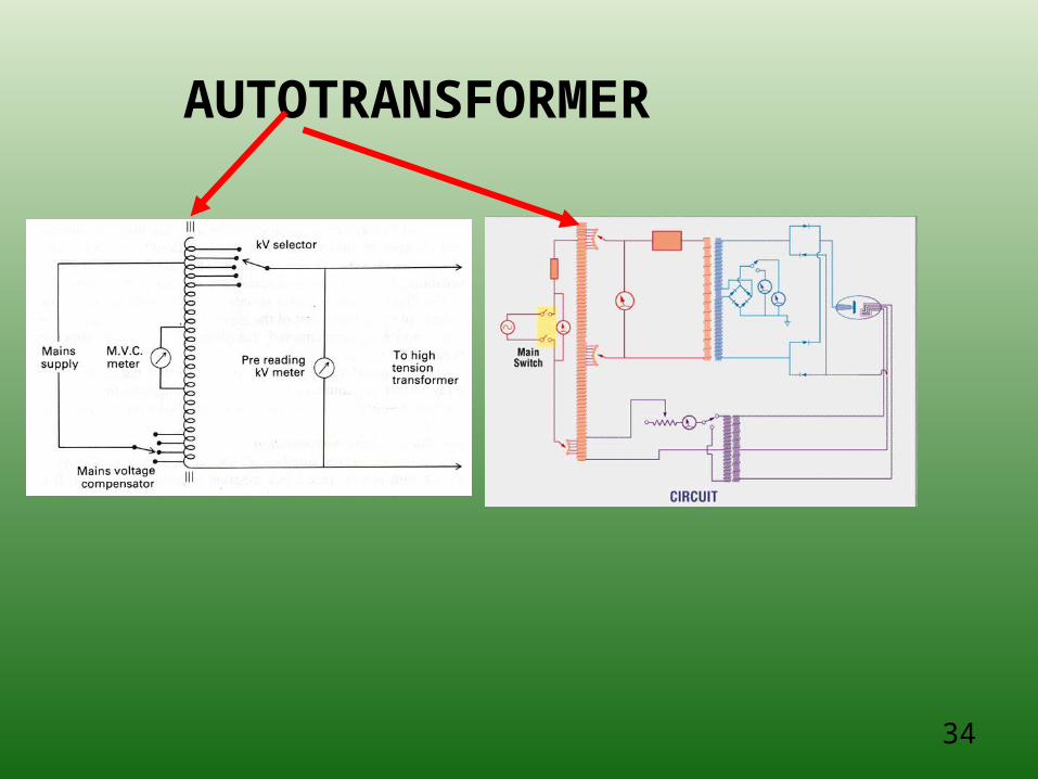
AUTOTRANSFORMER
35
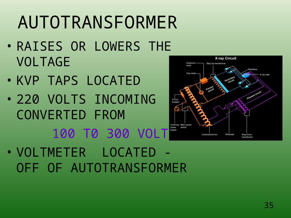
AUTOTRANSFORMER• RAISES OR LOWERS THE
VOLTAGE• KVP TAPS LOCATED• 220 VOLTS INCOMING
CONVERTED FROM
100 T0 300 VOLTS• VOLTMETER LOCATED -
OFF OF AUTOTRANSFORMER
36
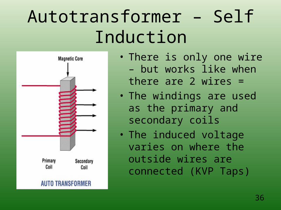
Autotransformer – Self Induction
• There is only one wire – but works like when there are 2 wires =
• The windings are used as the primary and secondary coils
• The induced voltage varies on where the outside wires are connected (KVP Taps)
37
Autotransformer
• The power for the x-ray imaging system is delivered first to the autotransformer
• The autotransformer works on the principle of electromagnetic induction
• It has one winding and one core
• There are a number of connections along its length
38
Autotransformer
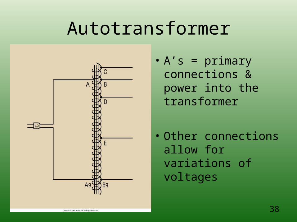
• A’s = primary connections & power into the transformer
• Other connections allow for variations of voltages
39
Autotransformer
• Is designed to step up voltage to about twice the input voltage value
• The increase in voltage is directly related to the number of turns
• Operates on SELF INDUCTION
40
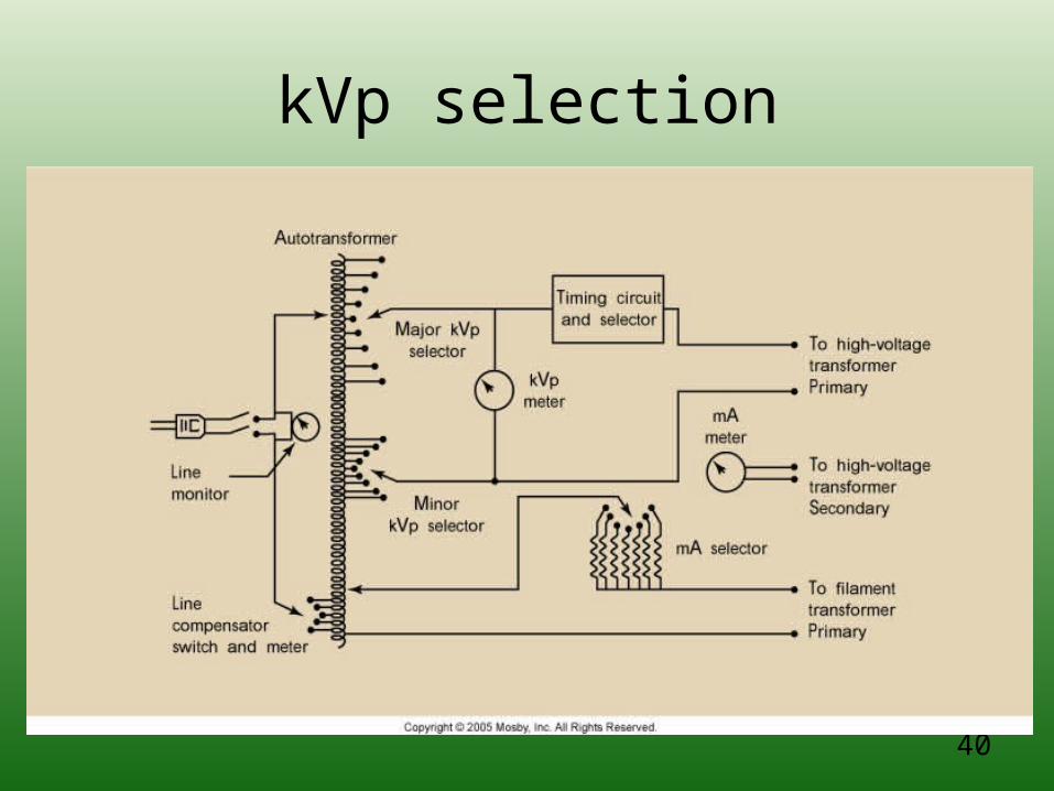
kVp selection
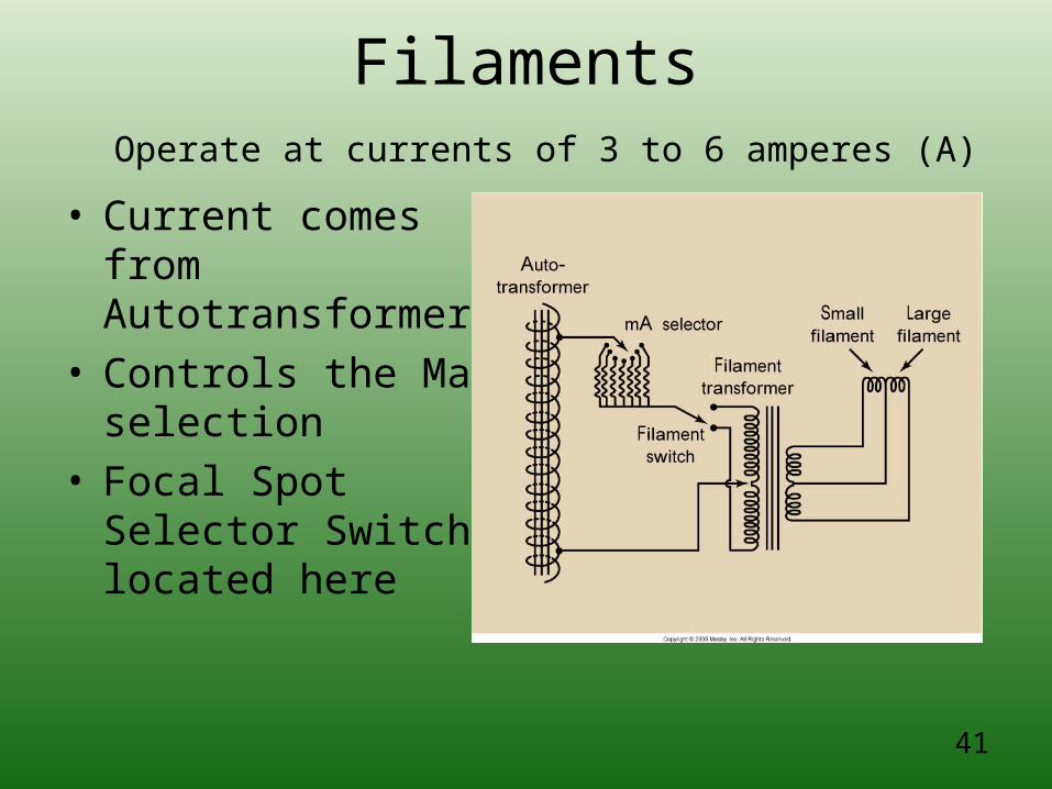
Filaments Operate at currents of 3 to 6 amperes (A)
41
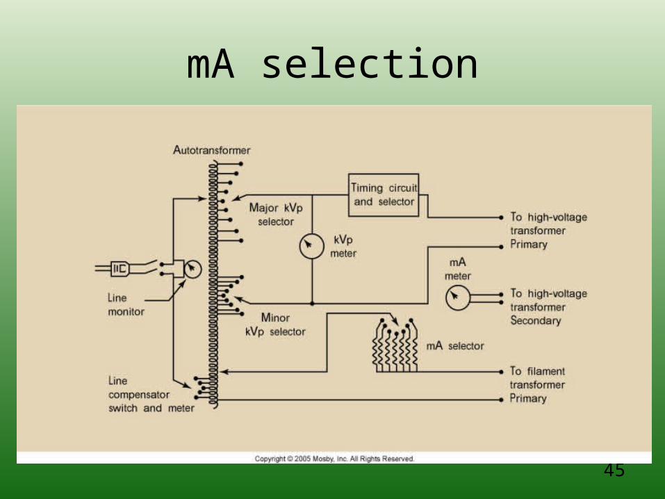
• Current comes from Autotransformer
• Controls the Ma selection
• Focal Spot Selector Switch located here
42
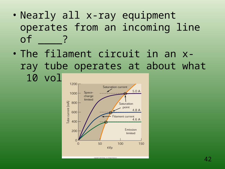
• Nearly all x-ray equipment operates from an incoming line of ____?
• The filament circuit in an x-ray tube operates at about what 10 volts of current
43
X-ray tube currentor Filament circuit
• A separate circuit crossing from cathode to anode
• Measured in milliampers (mA)
• What determines how many x-rays are created?
44
X-ray tube current or Filament circuit
• # of e- is determined by the temperature of the filament. The hotter the filament the more e-
• Are their any limiting factors to thermionic emission?
45
mA selection
46
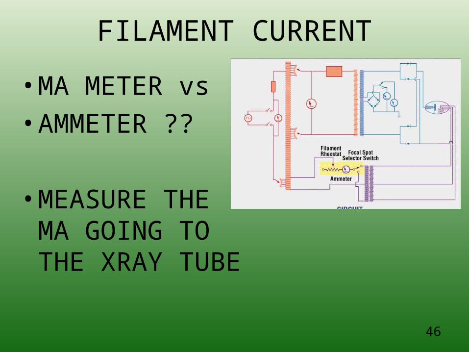
FILAMENT CURRENT
• MA METER vs
• AMMETER ??
• MEASURE THE MA GOING TO THE XRAY TUBE
47
RHEOSTAT
• VARIABLE REISITOR
• regulate the amount of resistance in a circuit
• • mA control is found between the
• AMMETER

48
Generator+ Tranformers(where the power comes from)
49
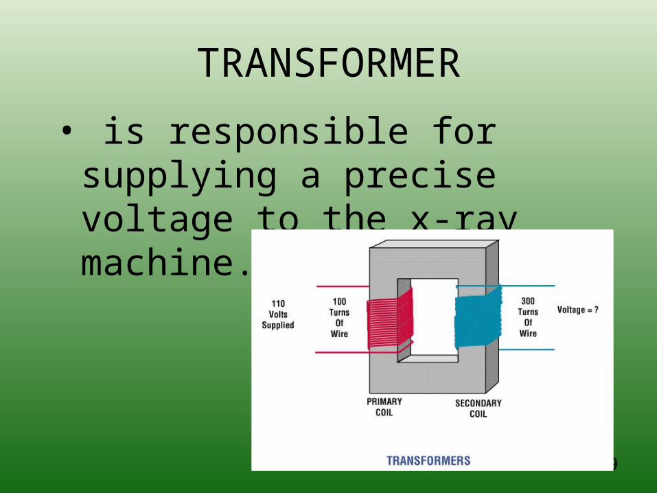
TRANSFORMER
• is responsible for supplying a precise voltage to the x-ray machine.
50
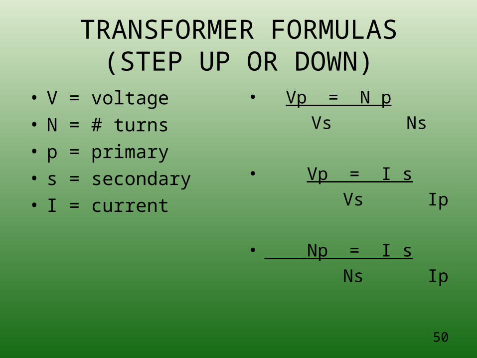
TRANSFORMER FORMULAS(STEP UP OR DOWN)
• V = voltage• N = # turns• p = primary• s = secondary• I = current
• Vp = N p
Vs Ns
• Vp = I s
Vs Ip
• Np = I s
Ns Ip
51
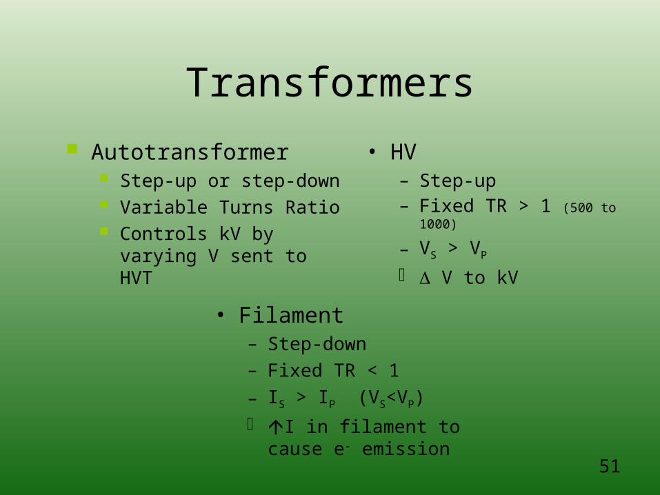
Transformers
• HV– Step-up– Fixed TR > 1 (500 to 1000)
– VS > VP
V to kV
• Filament– Step-down– Fixed TR < 1
– IS > IP (VS<VP)
I in filament to cause e- emission
Autotransformer Step-up or step-down Variable Turns Ratio Controls kV by varying
V sent to HVT
52
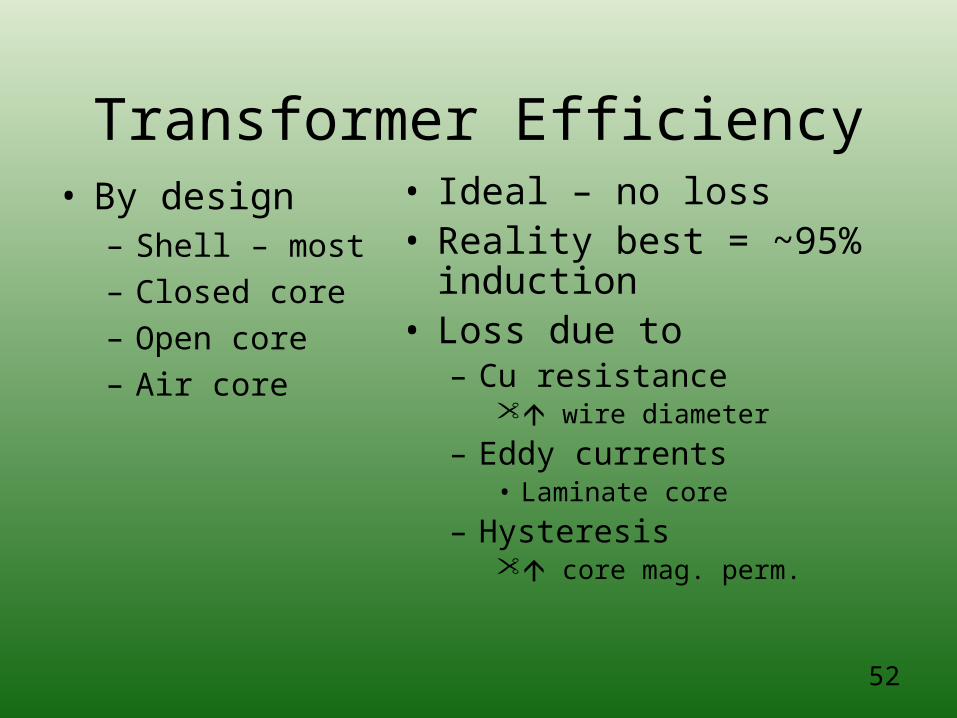
Transformer Efficiency• By design
– Shell – most– Closed core– Open core– Air core
• Ideal – no loss• Reality best = ~95%
induction• Loss due to
– Cu resistance wire diameter
– Eddy currents• Laminate core
– Hysteresis core mag. perm.
53
TRANSFORMERS(Step Up or Step Down)
• Increases the VOLTAGE going to the ANODE side of the tube OR
• 110 volts to 110,000 volts• Decreases the CURRENT
going to the CATHODE side of the tube
• 5 Amps to 50 milliamps
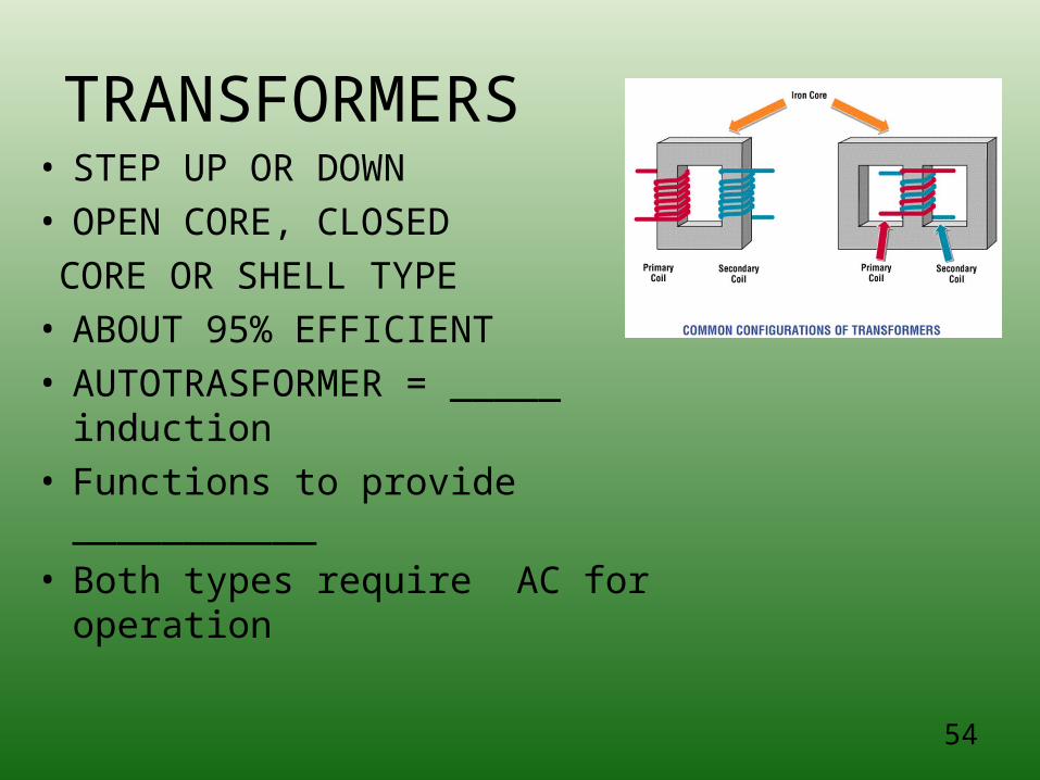
TRANSFORMERS• STEP UP OR DOWN• OPEN CORE, CLOSED
CORE OR SHELL TYPE• ABOUT 95% EFFICIENT• AUTOTRASFORMER = _____
induction• Functions to provide ___________• Both types require AC for
operation
54
55
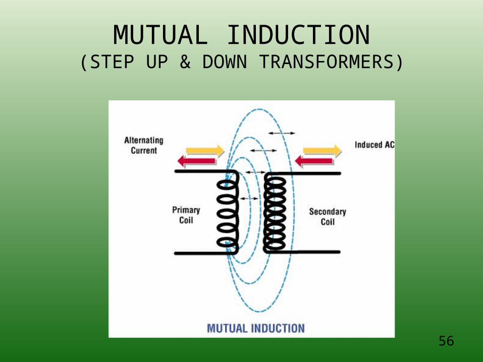
INDUCTION
• MUTUAL INDUCTION is the?
• SELF INDUCTION is the
• A transformer must have ________to produce an electric or magnetic current ?
56
MUTUAL INDUCTION(STEP UP & DOWN TRANSFORMERS)
57
AC
• Amplitude and polarity of the current vary with time
• AC – sinusoidal wave
• AC varies amplitude and periodic reversal of polarity
58
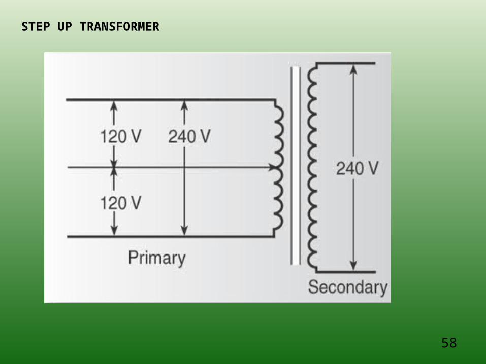
STEP UP TRANSFORMER
59
Electricity
• Is more efficiently tansported over long distances at low currents ahd high voltage in order to avoid large power losses
60
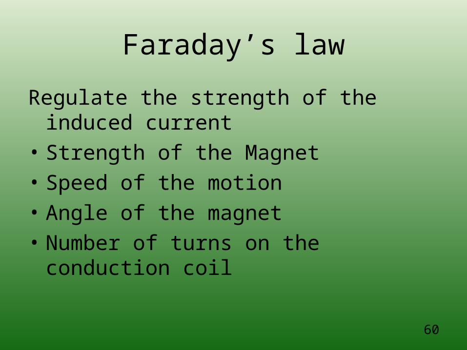
Faraday’s law
Regulate the strength of the induced current
• Strength of the Magnet
• Speed of the motion
• Angle of the magnet
• Number of turns on the conduction coil
61
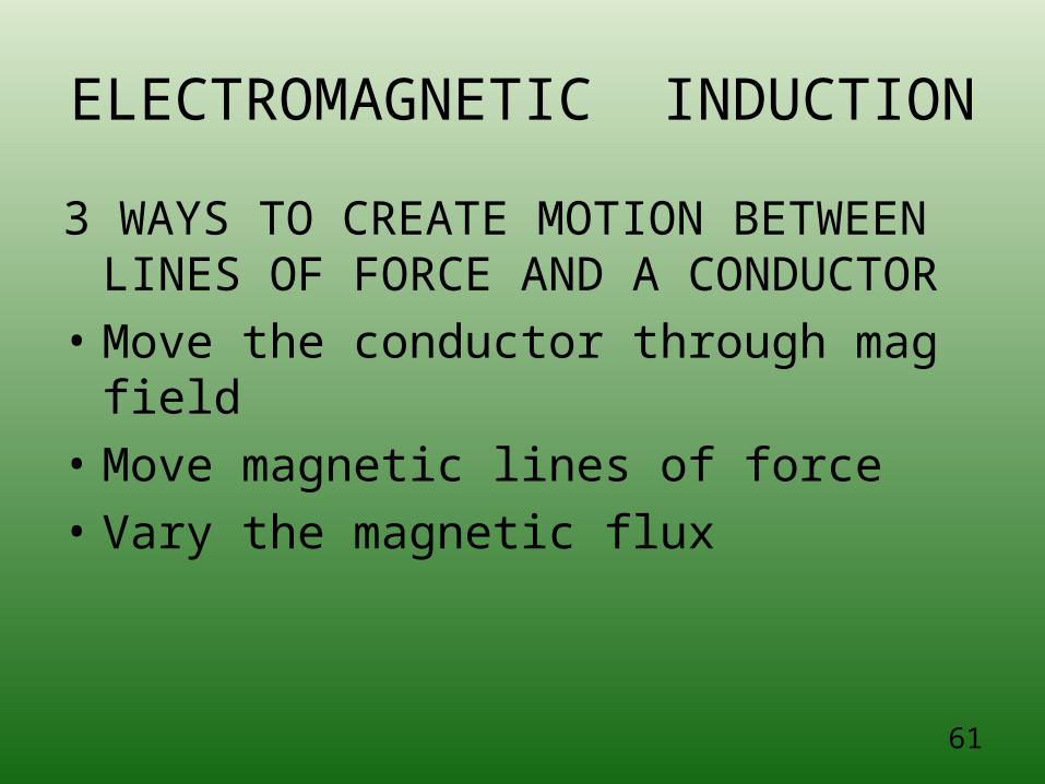
ELECTROMAGNETIC INDUCTION
3 WAYS TO CREATE MOTION BETWEEN LINES OF FORCE AND A CONDUCTOR
• Move the conductor through mag field
• Move magnetic lines of force
• Vary the magnetic flux
62
63
FUSES
• PREVENT SHOCK FROM A SHORT CIRCUIT –
• THE HIGHER CURRENT WILL MELT THE FUSE – STOPPING THE FLOW OF ELECTRICITY
• CIRCUIT BREAKERS HAVE REPLACED FUSES - POWER TOO HIGH IT WILL CUT OFF – not damage appliance
64
Question?
What is directly proportional to the number of x-rays reaching
the IR?

65
How do you convertmsec to sec?
1000ms = 1 sec
100ms = 0.1 sec
10 ms = 0.01 sec
66
mAs Timers
• Monitors the product of mA and exposure time
• Terminates the exposure when the desired mAs value is reached
• Located on the secondary side of the high-voltage transformer since actual tube current must be monitored

67
mAs Timers
• Designed to proved the highest mA for the shortest exposure
• What is the name of this type of imaging system generator? Hint: most modern and most common
68
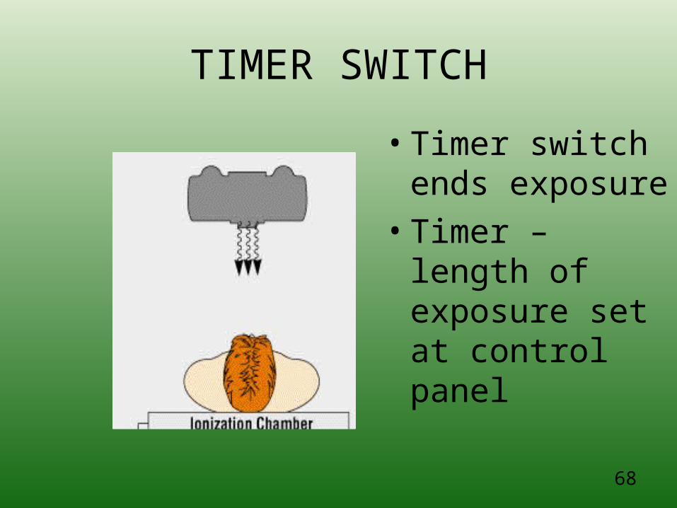
TIMER SWITCH
• Timer switch ends exposure
• Timer – length of exposure set at control panel
69
Exposure Timers
• The timer circuit is separate from the other main circuits of the imaging system
• It is a mechanical or electronic device whose action is to “make” and “break” the high voltage across the x-ray tube
• This is done on the primary side of the high voltage transformer.
70
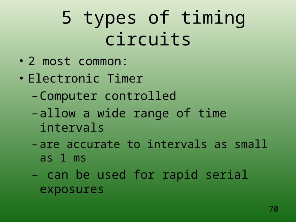
5 types of timing circuits
• 2 most common:
• Electronic Timer
– Computer controlled
– allow a wide range of time intervals– are accurate to intervals as small as 1 ms
– can be used for rapid serial exposures
71
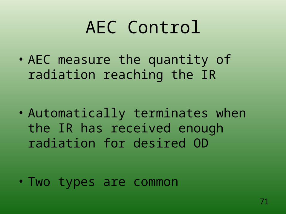
AEC Control
• AEC measure the quantity of radiation reaching the IR
• Automatically terminates when the IR has received enough radiation for desired OD
• Two types are common
72
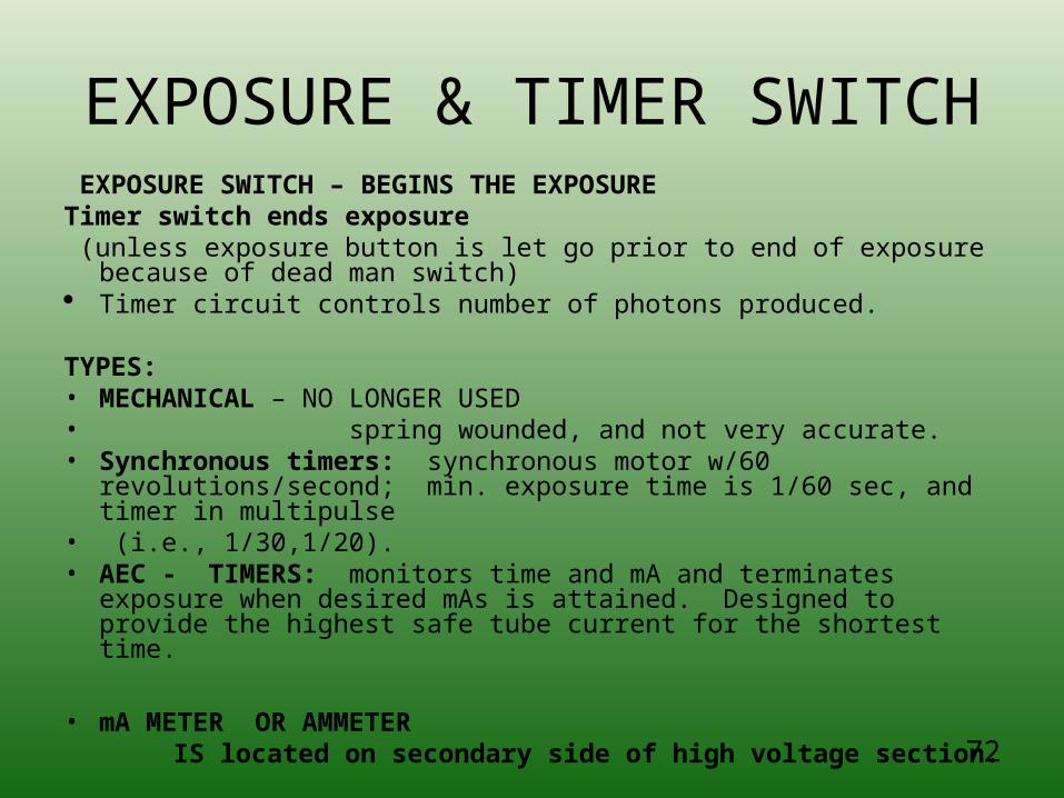
EXPOSURE & TIMER SWITCH EXPOSURE SWITCH – BEGINS THE EXPOSURETimer switch ends exposure (unless exposure button is let go prior to end of exposure because of
dead man switch) Timer circuit controls number of photons produced.
TYPES:• MECHANICAL – NO LONGER USED• spring wounded, and not very accurate.• Synchronous timers: synchronous motor w/60
revolutions/second; min. exposure time is 1/60 sec, and timer in multipulse
• (i.e., 1/30,1/20).• AEC - TIMERS: monitors time and mA and terminates exposure
when desired mAs is attained. Designed to provide the highest safe tube current for the shortest time.
• mA METER OR AMMETER IS located on secondary side of high voltage section.
73
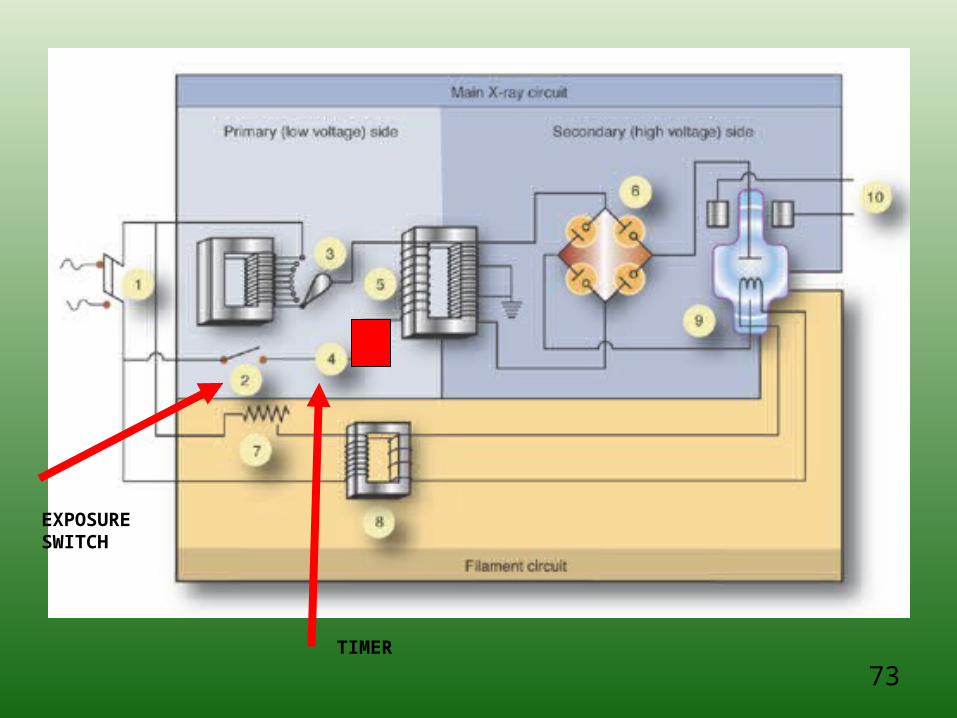
EXPOSURE SWITCH
TIMER
74
Back up time for AEC
• P 116 Bushong (8th ed)
• Back-up time should be set (electronic timer to 1.5 the expected exposure)
• Usually set automatically
• Exposure timer as short a 1 ms
• *Reg Rev Q: Manual reset timer = 6 sec (?)
75
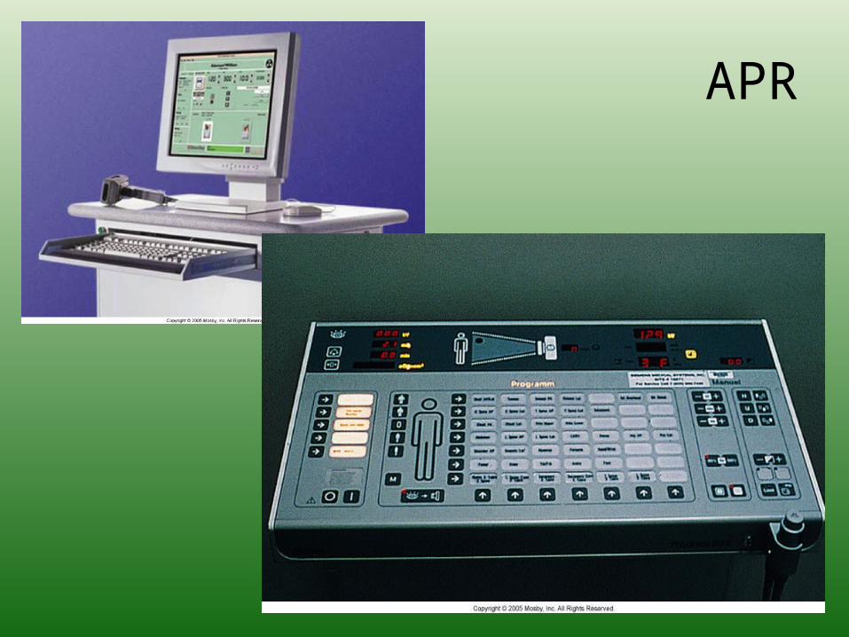
APR
• Anatomically Programmed Radiography (Ch 20)
– Radiologic Technologist selects on the console a picture of a written description of the anatomic part to be imaged and the patient body habitus
– A computer selects the appropriate kVp and mAs.
76
APR
77
Generator+ Tranformers(where the power comes from)
78
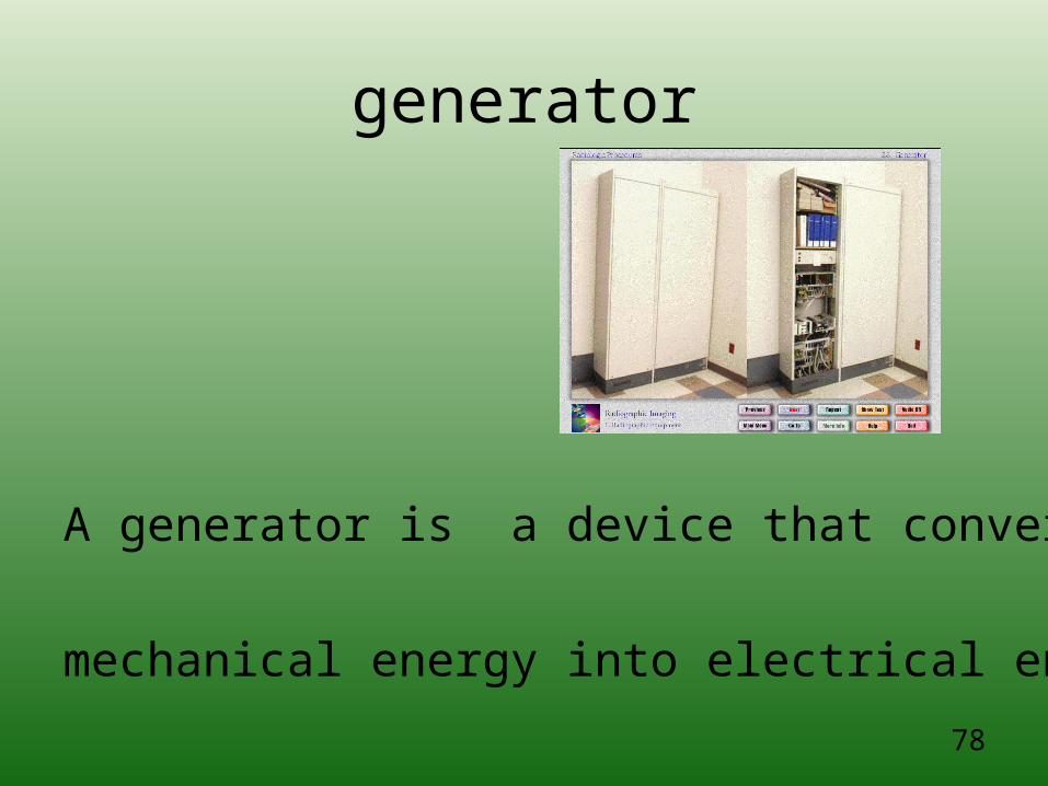
generator
A generator is a device that converts
mechanical energy into electrical energy
79
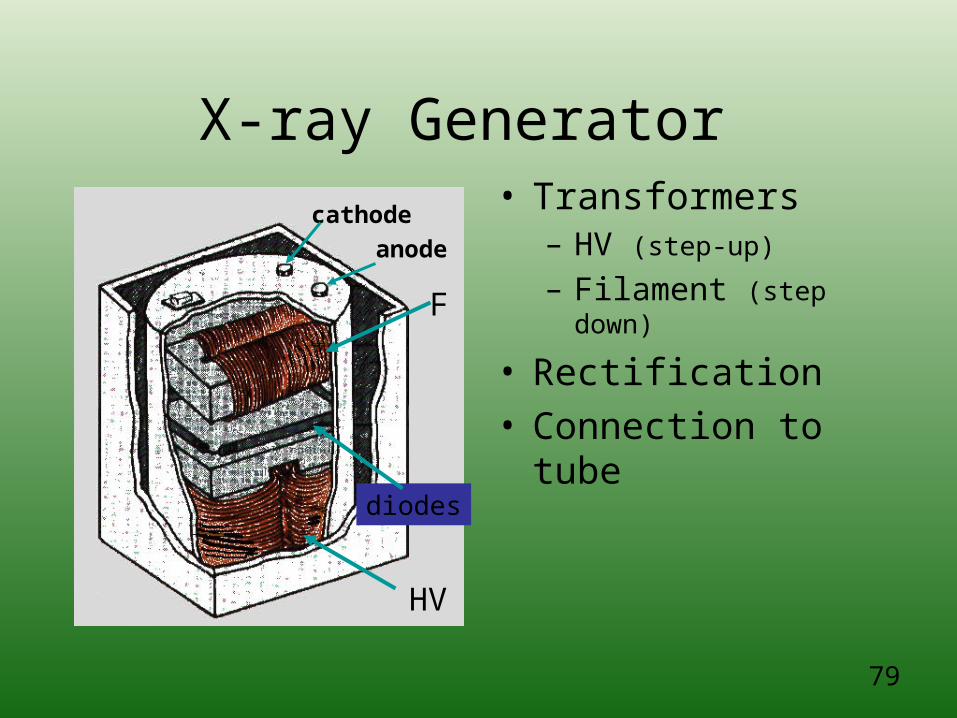
X-ray Generator • Transformers
– HV (step-up)
– Filament (step down)
• Rectification• Connection to tube
HV
F
diodes
anodecathode
80
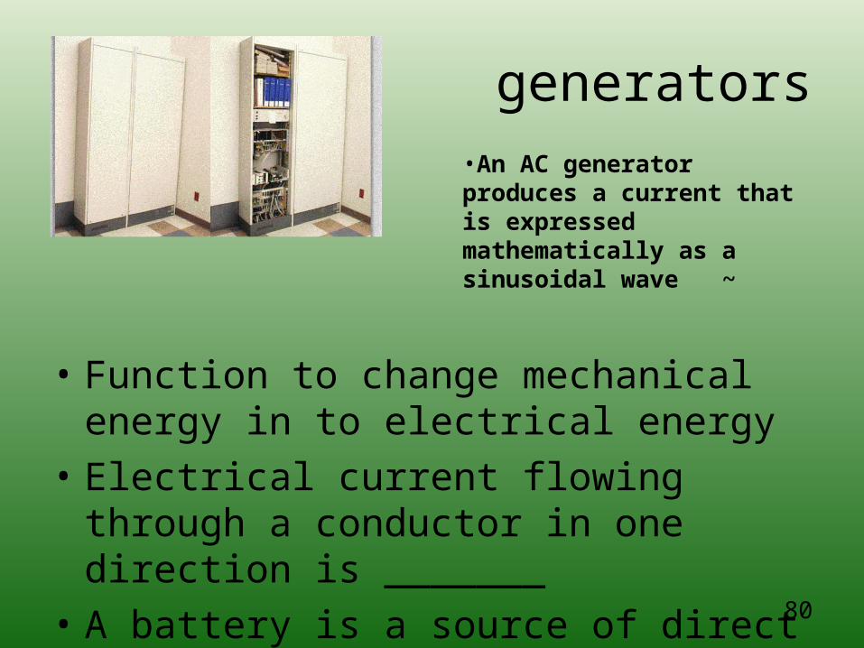
generators
• Function to change mechanical energy in to electrical energy
• Electrical current flowing through a conductor in one direction is _______
• A battery is a source of direct current
•An AC generator produces a current that is expressed mathematically as a sinusoidal wave ~
81
GENERATOR
• THAT CREATE AN ALTERNATING CURRENT ARE CALLED:
• AN ALTERNATOR –
• CONVERT MECHANICAL ENERGY INTO ELECTRICITY
82
• WHAT MEASURES ELECTRIC POTIENTAL = VOLT
• CURRENT = AMP
• ELECTRIC CIRCUIT IS THE PATHWAY FOR ELECTRIC CURRENT
83
High-Voltage Generator
• Responsible for increasing the output voltage from the autotransformer to the kVp necessary for x-ray production
• 3 parts: High-voltage transformer, filament transformer and rectifiers
84
High voltage transformer
• Or step up transformer
• Connected to the Major and Minor kVp selector
• Increases the volts from the autotransformer to kilovolts
85
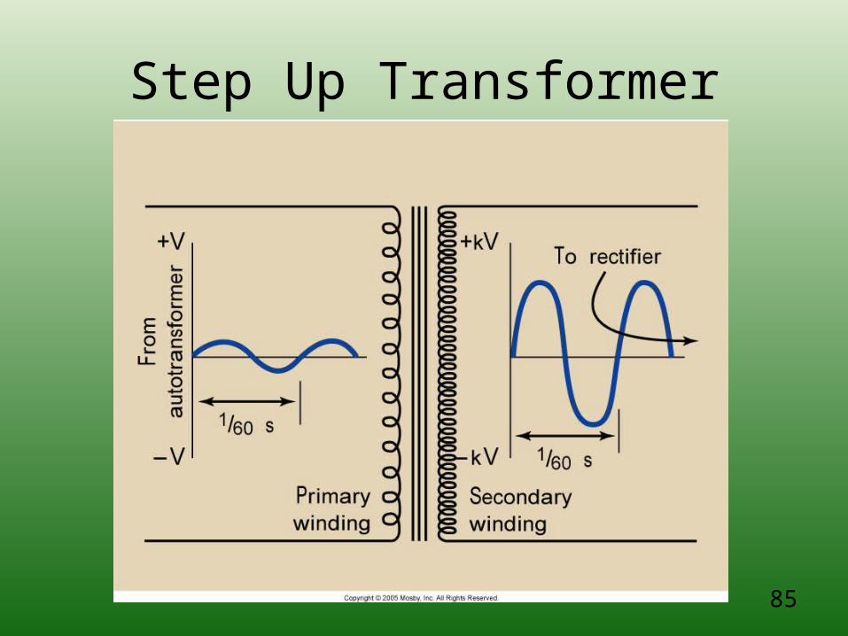
Step Up Transformer
86
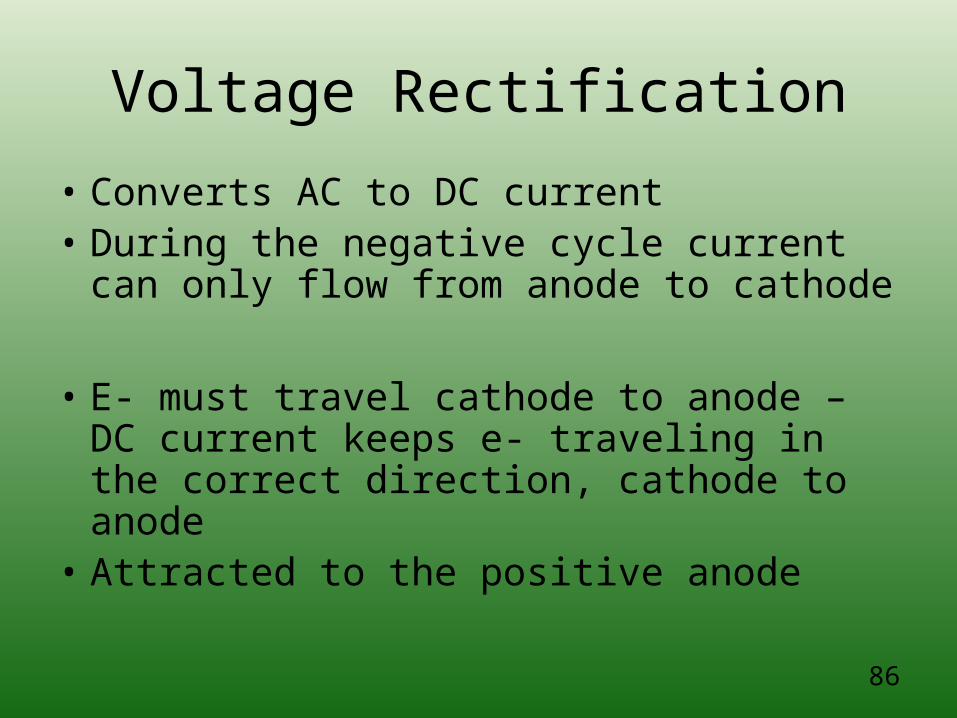
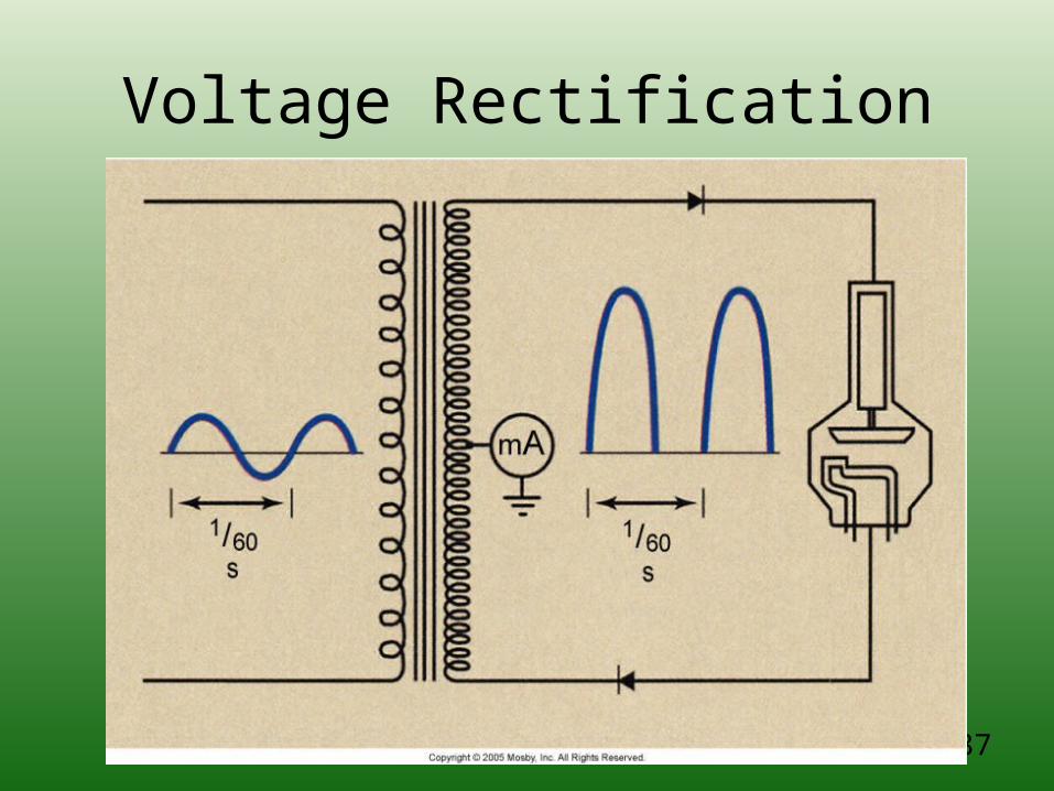
Voltage Rectification
• Converts AC to DC current• During the negative cycle current can only
flow from anode to cathode
• E- must travel cathode to anode – DC current keeps e- traveling in the correct direction, cathode to anode
• Attracted to the positive anode
87
Voltage Rectification
88
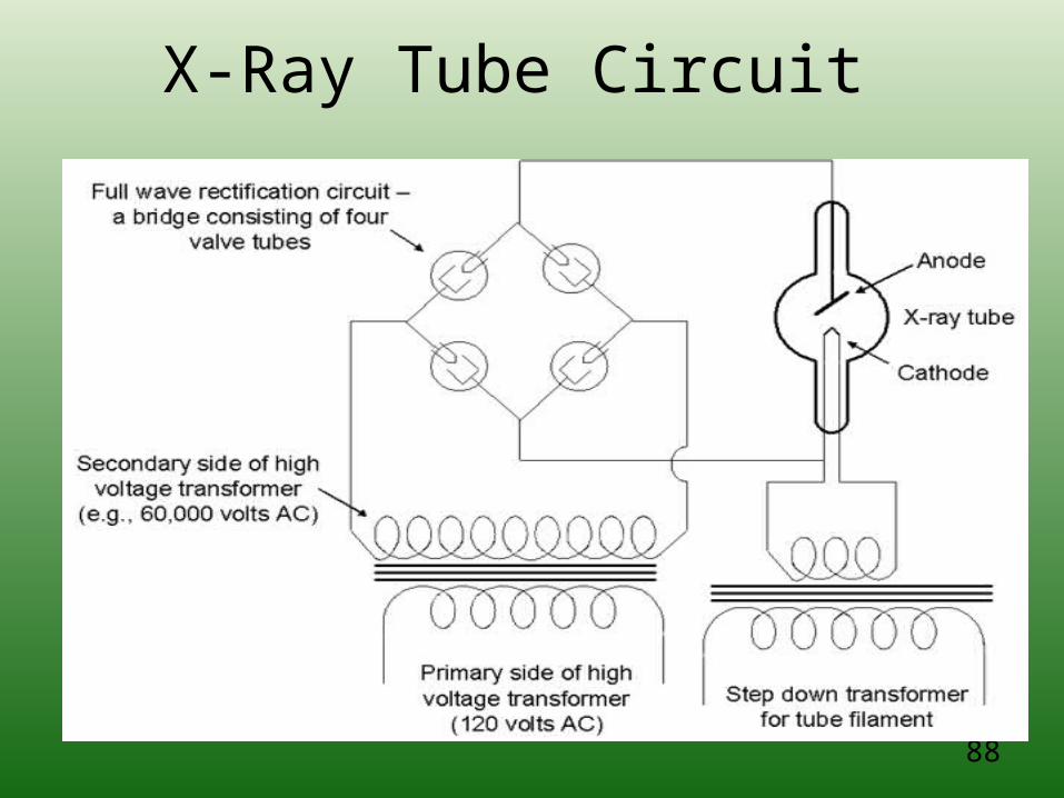
X-Ray Tube Circuit
89
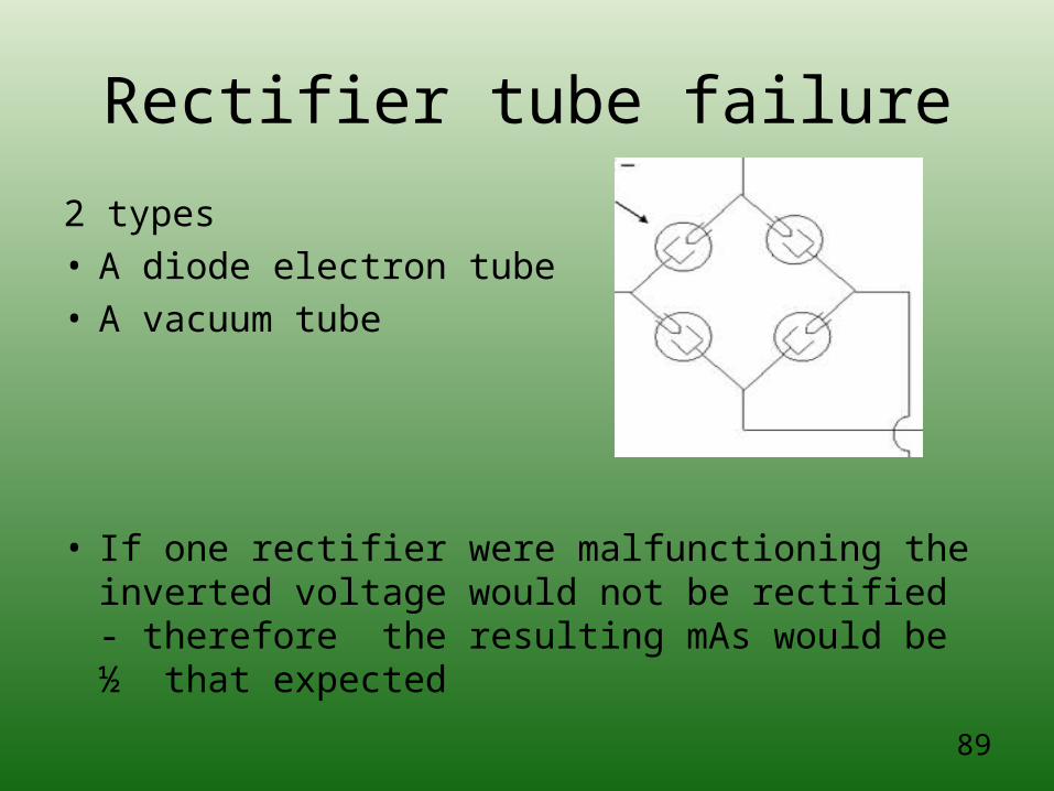
Rectifier tube failure
2 types• A diode electron tube • A vacuum tube
• If one rectifier were malfunctioning the inverted voltage would not be rectified - therefore the resulting mAs would be ½ that expected
90
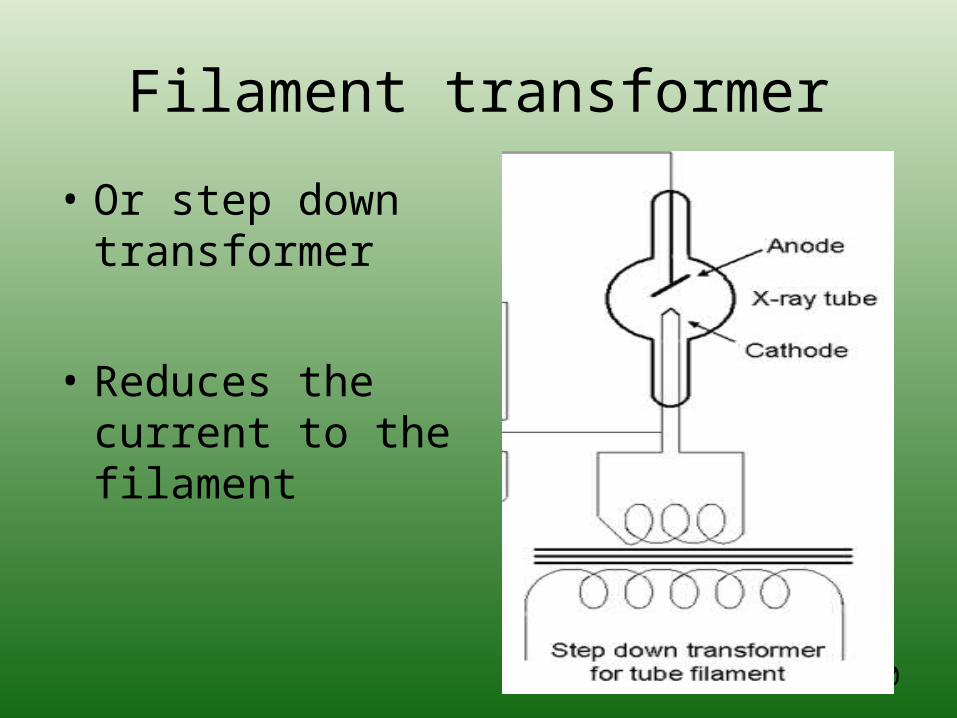
Filament transformer
• Or step down transformer
• Reduces the current to the filament
91
High-Voltage Generation – converts 110 volts
of AC to kilovolts of DC
• The generator is a FIXED component of the imaging system, not under the control of the technologist
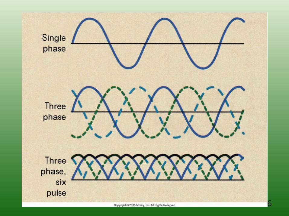
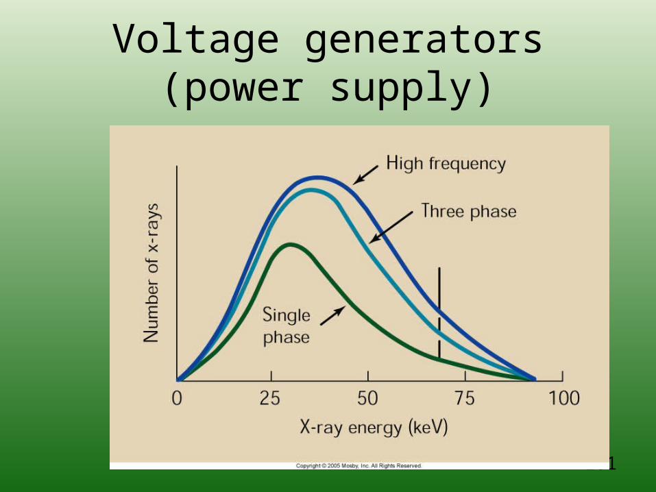
• Three basic types: single phase, three phase, and high frequency
• The generator affects the quality and quantity of photons produced

92
Single Phase Power= Pulsating X-ray beam
What are the 2 types?
93
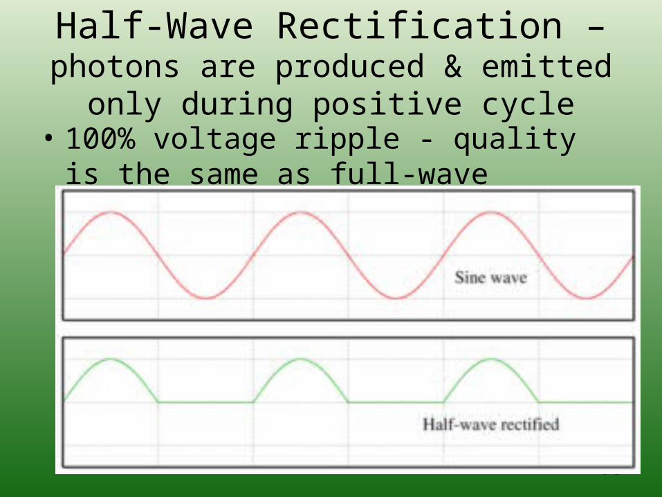
Half-Wave Rectification – photons are produced & emitted only during
positive cycle• 100% voltage ripple - quality is the same
as full-wave rectification but quantity is half
94
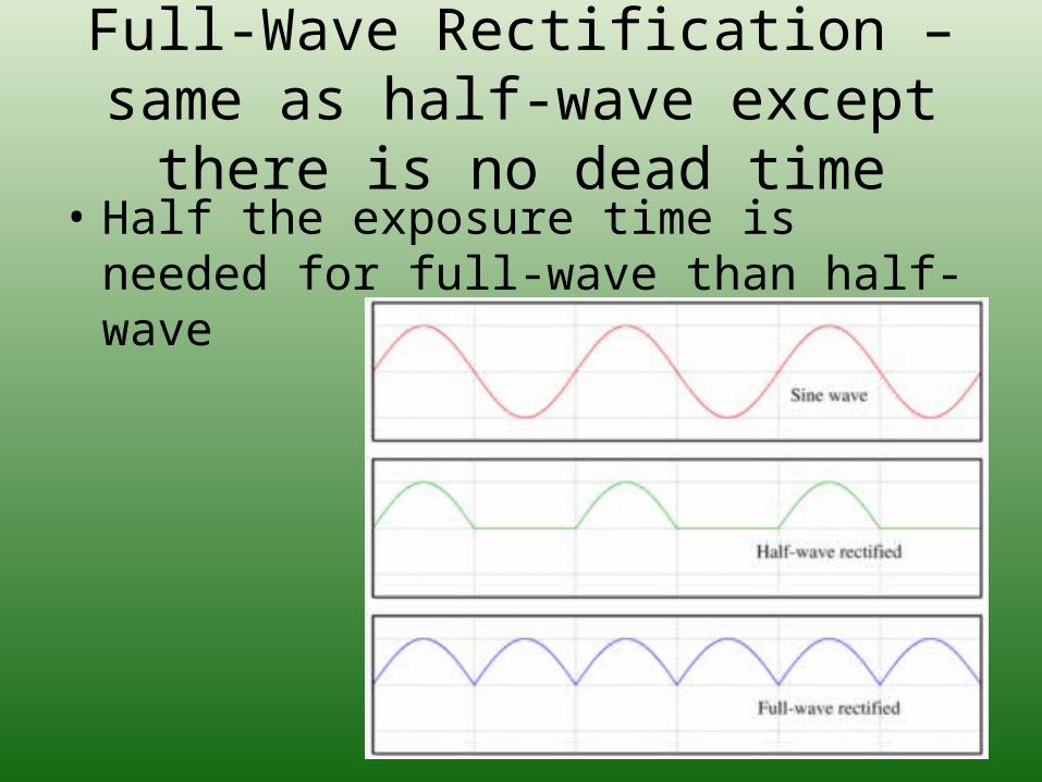
Full-Wave Rectification – same as half-wave except there is no dead
time• Half the exposure time is needed for full-
wave than half-wave
95
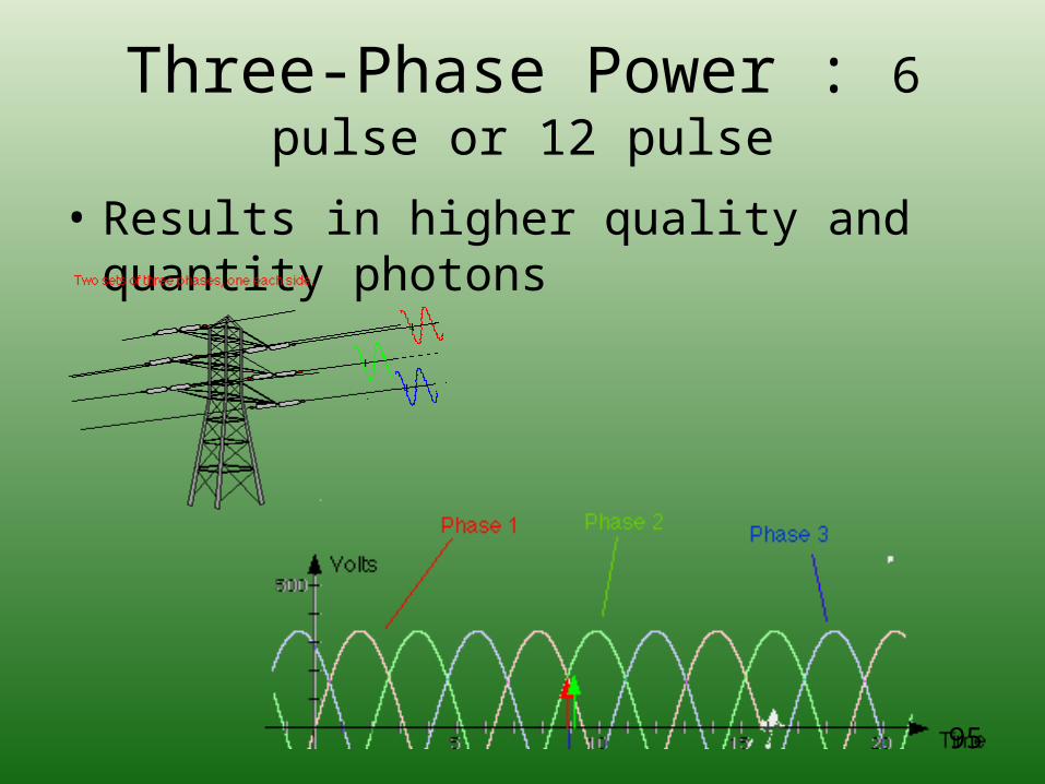
Three-Phase Power : 6 pulse or 12 pulse
• Results in higher quality and quantity photons
96
97
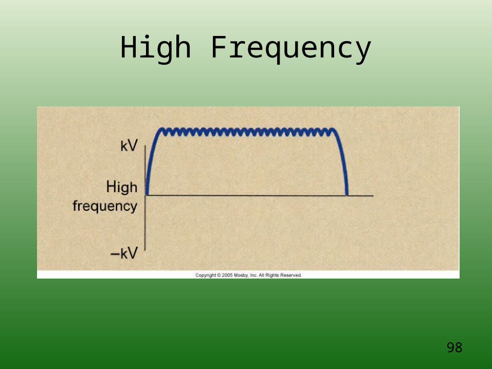
High-Frequency: nearly constant positive voltage
• Less than 1% ripple
• Modern X-ray machines have High-frequency falling-load generator– Automatically adjusts to the highest mA at the
shortest exposure time possible
98
High Frequency
99
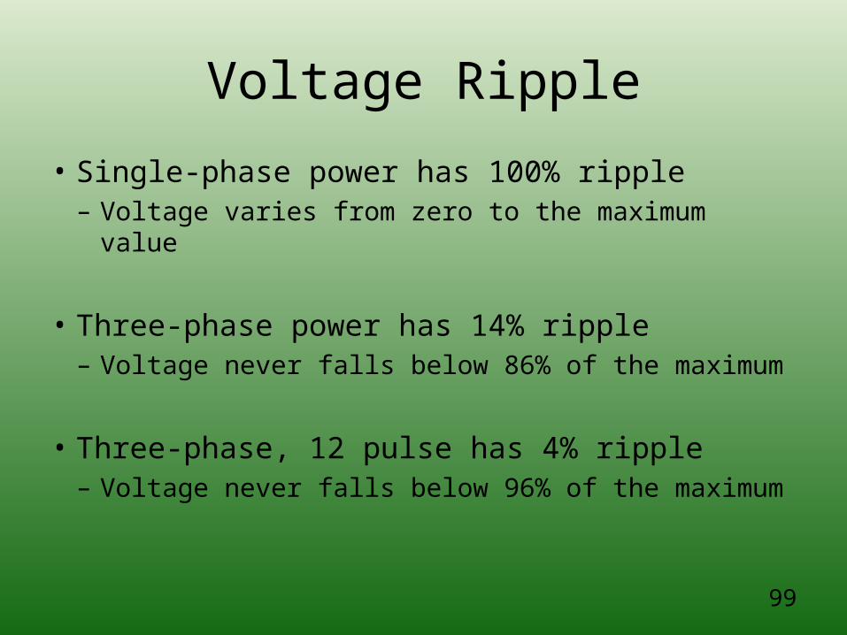
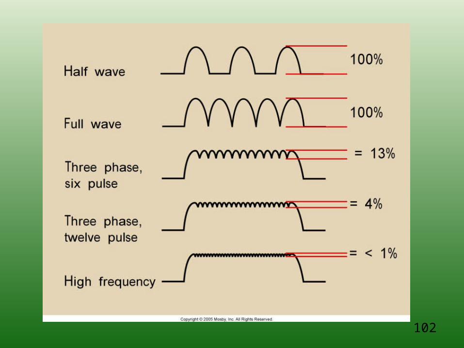
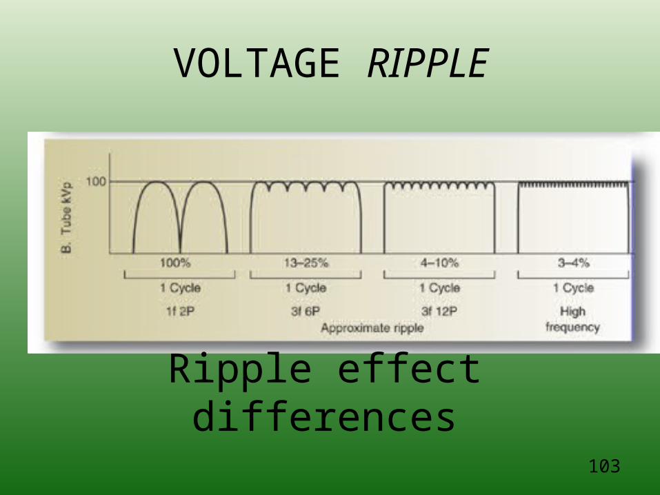
Voltage Ripple
• Single-phase power has 100% ripple– Voltage varies from zero to the maximum value
• Three-phase power has 14% ripple– Voltage never falls below 86% of the maximum
• Three-phase, 12 pulse has 4% ripple– Voltage never falls below 96% of the maximum
100
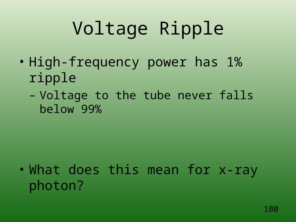
Voltage Ripple
• High-frequency power has 1% ripple– Voltage to the tube never falls below 99%
• What does this mean for x-ray photon?
101
Voltage generators (power supply)
102
103
VOLTAGE RIPPLE
Ripple effect differences
104
? What is missing?
105
• A three-phase generator operates on three single phase currents, each one out of phase by _____ degrees
106
Review Handouts
•Circuit Board
•Symbols
•Function
107
108
109
Questions on imaging systems?