Embed Size (px)
Citation preview

10. GEOMETRY OF NUTS
Type: DC See Pages 24 and 25.
RETURN GUIDE TYPE SINGLE FLANGE SINGLE NUT(Non-preloaded)
Simplest type using a single nut. For use in slight axialclearance.
Type: DP See Pages 26 and 27.
RETURN GUIDE TYPE SINGLE FLANGE SINGLE NUT(Over-size ball preloaded)
Designed to preload with a single nut. Steel balls whosediameter is slightly larger than clearance between screwshaft and thread groove of nut are put in the nut and pre-loaded. The ratio of load balls to spacer balls used there is1:1 Suitable for light preload (See Page 16.)
Type: DD See Pages 28 and 29.
RETURN GUIDE TYPE SINGLE FLANGE DOUBLENUT (Spacer preloaded)
Designed to preload with two nuts. A spacer with thicknessequivalent to amount of preload is put between these twonuts and preloaded as prescribed. Suitable for mediumpreload. (See Page 16.)
Type: TCS See Pages 30 and 31.
TUBULAR TYPE SMALL LEAD, SINGLE FLANGESINGLE NUT (Non-preloaded)
Simplest type using a single nut. For use in slight axialclearance.
Type: TPS See Pages 32 and 33.
TUBULAR TYPE SMALL LEAD, SINGLE FLANGESINGLE NUT (Over-size ball preloaded)
Designed to preload with a single nut. Steel balls whosediameter is slightly larger than clearance between screwshaft and thread groove of nut are put in the nut an pre-loaded. The ratio of load balls to spacer balls used there is1:1. Suitable for light preload (See Page 16.)
Type: TDS See Pages 34 and 35.
TUBULAR TYPE SMALL LEAD, SINGLE FLANGEDOUBLE NUT (Spacer preloaded)
Designed to preload with two nuts. A spacer with thicknessequivalent to amount of preload is put between these twonuts and preloaded as prescribed. Suitable for mediumpreload. (See Page 16.)

23
Type: TC……………………………… See Pages 36 to 39.
TUBULAR TYPE SINGLE FLANGE SINGLE NUT (Non-preloaded)
Simplest type using a single nut. For use in slight axialclearance.
Type: TP……………………………… See Pages 40 to 43.
TUBULAR TYPE SINGLE FLANGE SINGLE NUT(Over-size ball preloaded)
Designed to preload with a single nut. Steel balls whosediameter is slightly larger than clearance between screwshaft and thread groove of nut are put in the nut and pre-loaded. The ratio of load balls to spacer balls used there is1:1. Suitable for light load. (See Page 16.)
Type: TF……………………………… See Pages 44 to 47.
TUBULAR TYPE SINGLE FLANGE SINGLE NUT(Offset lead preloaded)
Designed to preload with a single nut. Lead along the centerof nut is enlarged by an amount of preload and preloaded.Suitable for medium preload. (See Page 16.)
Type: TD……………………………… See Pages 48 to 51.
TUBULAR TYPE SINGLE FLANGE DOUBLE NUT(Spacer preloaded)
Designed to preload with two nuts. A spacer with thicknessequivalent to amount of preload is put between these twonuts and preloaded as prescribed. Suitable for medium andheavy preload. (See Page 16.)
Type: TCL ………………………… See Pages 52 and 53.
TUBULAR TYPE HIGH LEAD SINGLE FLANGESINGLE NUT (Non-preloaded)
Simplest type using a single nut. For use in slight axialclearance.
Type: TPL ………………………… See Pages 54 and 55.
TUBULAR TYPE HIGH LEAD SINGLE FLANGESINGLE NUT (Over-size ball preloaded)
Designed to preload with a single nut. Steel balls whosediameter is slightly larger than clearance between screwshaft and thread groove of nut are put in the nut and pre-loaded. The ratio of load balls to spacer balls used there is1:1. Suitable for light load (See Page 16.)

W
45°� 45°�
W
30°� 30°�
H�
4-X drilled
Y countersink Depth Z
4-X drilled
Y countersink Depth Z
d R Da dm dr Turns ×Circ. Ca C0a K
DC 0301 3 1 0.600 3.15 2.5 3.7×1 34 64 4.2
DC 0401 4 1 0.800 4.15 3.3 3.7×1 59 108 5.4
DC 0501 5 1 0.800 5.15 4.3 3.7×1 69 137 6.9
DC 0601 1 0.800 6.15 5.3 74 167 7.8
DC 0601.56
1.5 1.000 6.2 5.13.7×1
98 196 7.8
DC 0602 2(1/16)
6.3 4.6 177 304 8.31.5875
DC 08018
1 0.800 8.15 7.33.7×1
83 206 9.8
DC 0801.5 1.5 1.000 8.2 7.1 108 265 9.8
DC 100110
1 0.800 10.15 9.33.7×1
88 265 12
DC 1001.5 1.5 1.000 10.2 9.1 127 343 12
DC 1201 12 1 0.800 12.15 11.3 3.7×1 98 314 14
DC 1401 14 1 0.800 14.15 13.3 3.7×1 108 363 16
24
RETURN GUIDE TYPE SINGLE FLANGE SINGLE NUTDC TYPE (Non-preloaded)
R type (standard) H type
Nut typeScrew O.D Lead Steel ball
dia.Center-circledia. of steelball
Screw rootdia.
Number ofturns andcircuits
Basic rated load(N)
Dynamic Static
Stiffness (N/μm)

D A B F L W X Y Z H
9 22 4 15 19 15 3 5.5 2 15 DC 0301
11 24 4 16 20 17 3 5.5 2 16 DC 0401
12 25 4 16 20 18 3 5.5 2 17 DC 0501
13 30 5 16 21 21.5 3.4 6.5 3 20 DC 0601
14 30 5 18 23 22 3.4 6.5 3 20 DC 0601.5
18 34 5 22 27 26 3.4 6.5 3 22 DC 0602
16 32 5 16 21 24 3.4 6.5 3 21 DC 0801
16 32 5 18 23 24 3.4 6.5 3 21 DC 0801.5
19 39 6 16 22 29 4.5 8 4 26 DC 1001
19 39 6 18 24 29 4.5 8 4 26 DC 1001.5
21 41 6 16 22 31 4.5 8 4 26 DC 1201
24 47 8 16 24 35 5.5 9.5 5.5 30 DC 1401
25
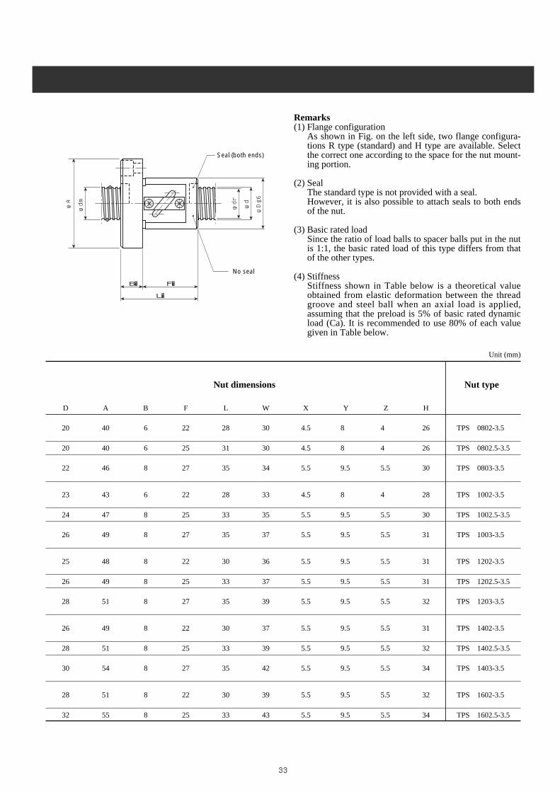
Remarks(1) Flange configuration
As shown in Fig. on the left side, two flange configura-tions R type (standard) and H type are available. Selectthe correct one according to the space for the nutmouting portion.
(2) SealThe standard type is not provided with a seal.However, it is also possible to attach seals to both endsof the nut.
(3) StiffnessStiffness shown in Table below is a theoretical valueobtained from elastic deformation between the threadgroove and steel ball when an axial load is equivalent to30% of basic rated dynamic load (Ca) is applied. It isrecommended to use 80% of each value given in Tablebelow.
Unit (mm)
B� F�
L�
φA
φdm φdr
φd
φDg6
Seal (both ends)
No seal
Nut dimensions Nut type

W
45°� 45°�
W
30°� 30°�
H�
4-X drilled
Y countersink Depth Z
4-X drilled
Y countersink Depth Z
26
d R Da dm dr Turns ×Circ. Ca C0a K
DP 0301 3 1 0.600 3.15 2.5 3.7×1 25 34 3.9
DP 0401 4 1 0.800 4.15 3.3 3.7×1 34 54 4.6
DP 0501 5 1 0.800 5.15 4.3 3.7×1 39 69 5.6
DP 0601 1 0.800 6.15 5.3 44 79 6.6
DP 0601.56
1.5 1.000 6.2 5.13.7×1
59 98 6.9
DP 0602 2(1/16)
6.3 4.6 113 162 7.41.5875
DP 08018
1 0.800 8.15 7.33.7×1
49 108 8.1
DP 0801.5 1.5 1.000 8.2 7.1 69 132 8.5
DP 100110
1 0.800 10.15 9.33.7×1
59 132 9.8
DP 1001.5 1.5 1.000 10.2 9.1 79 167 11
DP 1201 12 1 0.800 12.15 11.3 3.7×1 64 157 12
DP 1401 14 1 0.800 14.15 13.3 3.7×1 69 181 13
RETURN GUIDE TYPE SINGLE FLANGE SINGLE NUTDP TYPE (Oversize ball preloaded)
R type (standard) H type
Nut typeScrew O.D Lead Steel ball
dia.Center-circledia. of steelball
Screw rootdia.
Number ofturns andcircuits
Basic rated load(N)
Dynamic Static
Stiffness (N/μm)

27
D A B F L W X Y Z H
9 22 4 15 19 15 3 5.5 2 15 DP 0301
11 24 4 16 20 17 3 5.5 2 16 DP 0401
12 25 4 16 20 18 3 5.5 2 17 DP 0501
13 30 5 16 21 21.5 3.4 6.5 3 20 DP 0601
14 30 5 18 23 22 3.4 6.5 3 20 DP 0601.5
18 34 5 22 27 26 3.4 6.5 3 22 DP 0602
16 32 5 16 21 24 3.4 6.5 3 21 DP 0801
16 32 5 18 23 24 3.4 6.5 3 21 DP 0801.5
19 39 6 16 22 29 4.5 8 4 26 DP 1001
19 39 6 18 24 29 4.5 8 4 26 DP 1001.5
21 41 6 16 22 31 4.5 8 4 26 DP 1201
24 47 8 16 24 35 5.5 9.5 5.5 30 DP 1401
Remarks(1) Flange configuration
As shown in Fig. on the left side, two flange configura-tions R type (standard) and H type are available. Selectthe correct one according to the space for the nutmouting portion.
(2) SealThe standard type is not provided with a seal.However, it is also possible to attach seals to both endsof the nut.
(3) Basic rated loadSince sthe ratio of load balls to spacer balls put in thenut is 1:1, the basic rated load of this type differs fromthat of the other types.
(4) StiffnessStiffness shown in Table below is a theoretical valueobtained from elastic deformation between the threadgroove and steel ball when an axial load is applied,assuming that the preload is 5% of basic rated dynamicload (Ca). It is recommended to use 80% of each valuegiven in Table below.
B� F�
L�
φA
φdm φdr
φd
φDg6
Seal (both ends)
No seal
Unit (mm)
Nut dimensions Nut type

W
45°� 45°�
W
30°� 30°�
H�
4-X drilled
Y countersink Depth Z
4-X drilled
Y countersink Depth Z
28
d R Da dm dr Turns ×Circ. Ca C0a K
DD 0601 1 0.800 6.15 5.3 74 167 16
DD 0601.56
1.5 1.000 6.2 5.13.7×1
98 196 16
DD 0602 2(1/16)
6.3 4.6 177 304 171.5875
DD 08018
1 0.800 8.15 7.33.7×1
83 206 20
DD 0801.5 1.5 1.000 8.2 7.1 108 265 20
DD 100110
1 0.800 10.15 9.33.7×1
88 265 24
DD 1001.5 1.5 1.000 10.2 9.1 127 343 25
DD 1201 12 1 0.800 12.15 11.3 3.7×1 98 314 27
DD 1401 14 1 0.800 14.15 13.3 3.7×1 108 363 30
RETURN GUIDE TYPE SINGLE FLANGE SINGLE NUTDD TYPE (Spacer preloaded)
R type (standard) H type
Nut typeScrew O.D Lead Steel ball
dia.Center-circledia. of steelball
Screw rootdia.
Number ofturns andcircuits
Basic rated load(N)
Dynamic Static
Stiffness (N/μm)

29
D A B F E L W X Y Z H
13 30 5 16 2 43 21.5 3.4 6.5 3 20 DD 0601
14 30 5 18 2 47 22 3.4 6.5 3 20 DD 0601.5
18 34 5 22 4 57 26 3.4 6.5 3 22 DD 0602
16 32 5 16 2 43 24 3.4 6.5 3 21 DD 0801
16 32 5 18 2 47 24 3.4 6.5 3 21 DD 0801.5
19 39 6 16 2 44 29 4.5 8 4 26 DD 1001
19 39 6 18 2 48 29 4.5 8 4 26 DD 1001.5
21 41 6 16 2 44 31 4.5 8 4 26 DD 1201
24 47 8 16 4 48 35 5.5 9.5 5.5 30 DD 1401
Remarks(1) Flange configuration
As shown in Fig. on the left side, two flange configu-rations R type (standard) and H type are available.Select the correct one according to the space for thenut mounting portion.
(2) SealThe standard type is not provided with a seal.However, it is also possible to attach seals to bothends of the nut.
(3) StiffnessStiffness shown in Table below is a theoretical valueobtained from elastic deformation between the threadgroove and steel ball when an axial load is applied,assuming that the preload is 10% of basic rateddynamic load (Ca). It is recommended to use 80% ofeach value given in Table below.
B� F� E
L�
φA
φdm φdr
φd
φD
φDg6
-0.1�
-0.3
Seal (both ends) Preload fixing key (2 locations)
No seal Spacer
Unit (mm)
Nut dimensions Nut type

W
45°� 45°�
W
30°� 30°�
H�
4-X drilled
Y countersink Depth Z
4-X drilled
Y countersink Depth Z
30
d R Da dm dr Turns ×Circ. Ca C0a K
TCS 0802-3.5 2(1/16)
8.3 6.6 245 400 111.5875
TCS 0802.5-3.5 8 2.5 2.000 8.3 6.2 3.5×1 320 495 11
TCS 0803-3.5 3(3/32)
8.3 5.8 390 575 112.381
TCS 1002-3.5 2(1/16)
10.3 8.6 270 505 131.5875
TCS 1002.5-3.5 10 2.5 2.000 10.3 8.2 3.5×1 365 630 13
TCS 1003-3.5 3(3/32)
10.3 7.8 450 735 142.381
TCS 1202-3.5 2(1/16)
12.3 10.6 295 610 151.5875
TCS 1202.5-3.5 12 2.5 2.000 12.3 10.2 3.5×1 400 760 16
TCS 1203-3.5 3(3/32)
12.3 9.8 500 895 162.381
TCS 1402-3.5 2(1/16)
14.3 12.6 315 715 171.5875
TCS 1402.5-3.5 14 2.5 2.000 14.3 12.2 3.5×1 430 890 18
TCS 1403-3.5 3(3/32)
14.3 11.8 540 1050 182.381
TCS 1602-3.5 2(1/16)
16.3 14.6 335 820 191.5875
TCS 1602.5-3.5
16
2.5 2.000 16.3 14.2
3.5×1
455 1030 20
TUBULAR TYPE SMALL LEAD SINGLE FLANGE SINGLE NUTTCS TYPE (Non-preloaded)
R type (standard) H type
Nut typeScrew O.D Lead Steel ball
dia.Center-circledia. of steelball
Screw rootdia.
Number ofturns andcircuits
Basic rated load(N)
Dynamic Static
Stiffness (N/μm)

31
D A B F L W X Y Z H
20 40 6 22 28 30 4.5 8 4 26 TCS 0802-3.5
20 40 6 25 31 30 4.5 8 4 26 TCS 0802.5-3.5
22 46 8 27 35 34 5.5 9.5 5.5 30 TCS 0803-3.5
23 43 6 22 28 33 4.5 8 4 28 TCS 1002-3.5
24 47 8 25 33 35 5.5 9.5 5.5 30 TCS 1002.5-3.5
26 49 8 27 35 37 5.5 9.5 5.5 31 TCS 1003-3.5
25 48 8 22 30 36 5.5 9.5 5.5 31 TCS 1202-3.5
26 49 8 25 33 37 5.5 9.5 5.5 31 TCS 1202.5-3.5
28 51 8 27 35 39 5.5 9.5 5.5 32 TCS 1203-3.5
26 49 8 22 30 37 5.5 9.5 5.5 31 TCS 1402-3.5
28 51 8 25 33 39 5.5 9.5 5.5 32 TCS 1402.5-3.5
30 54 8 27 35 42 5.5 9.5 5.5 34 TCS 1403-3.5
28 51 8 22 30 39 5.5 9.5 5.5 32 TCS 1602-3.5
32 55 8 25 33 43 5.5 9.5 5.5 34 TCS 1602.5-3.5
Remarks(1) Flange configuration
As shown in Fig. on the left side, two flange configura-tions R type (standard) and H type are available. Selectthe correct one according to the space for the nut mount-ing portion.
(2) SealThe standard type is not provided with a seal.However, it is also possible to attach seals to both endsof the nut.
(3) StiffnessStiffness shown in Table below is a theoretical valueobtained from elastic deformation between the threadgroove and steel ball when an axial load is applied,assuming that the preload is 30% of basic rated dynamicload (Ca). It is recommended to use 80% of each valuegiven in Table below.
B� F�
L�
φA
φdm φdr
φd
φDg6
Seal (both ends)
No seal
Unit (mm)
Nut dimensions Nut type

W
45°� 45°�
W
30°� 30°�
H�
4-X drilled
Y countersink Depth Z
4-X drilled
Y countersink Depth Z
32
d R Da dm dr Turns ×Circ. Ca C0a K
TPS 0802-3.5 2(1/16)
8.3 6.6 155 200 9.41.5875
TPS 0802.5-3.5 8 2.5 2.000 8.3 6.2 3.5×1 200 245 9.5
TPS 0803-3.5 3(3/32)
8.3 5.8 245 290 9.62.381
TPS 1002-3.5 2(1/16)
10.3 8.6 170 255 111.5875
TPS 1002.5-3.5 10 2.5 2.000 10.3 8.2 3.5×1 230 315 12
TPS 1003-3.5 3(3/32)
10.3 7.8 285 365 122.381
TPS 1202-3.5 2(1/16)
12.3 10.6 185 305 131.5875
TPS 1202.5-3.5 12 2.5 2.000 12.3 10.2 3.5×1 250 380 13
TPS 1203-3.5 3(3/32)
12.3 9.8 315 445 142.381
TPS 1402-3.5 2(1/16)
14.3 12.6 200 360 151.5875
TPS 1402.5-3.5 14 2.5 2.000 14.3 12.2 3.5×1 270 445 15
TPS 1403-3.5 3(3/32)
14.3 11.8 340 525 152.381
TPS 1602-3.5 2(1/16)
16.3 14.6 210 410 161.5875
TPS 1602.5-3.5
16
2.5 2.000 16.3 14.2
3.5×1
290 510 17
TUBULAR TYPE SMALL LEAD SINGLE FLANGE SINGLE NUTTPS TYPE (Oversize ball preloaded)
Nut typeScrew O.D Lead Steel ball
dia.Center-circledia. of steelball
Screw rootdia.
Number ofturns andcircuits
Basic rated load(N)
Dynamic Static
Stiffness (N/μm)
R type (standard) H type
33
D A B F L W X Y Z H
20 40 6 22 28 30 4.5 8 4 26 TPS 0802-3.5
20 40 6 25 31 30 4.5 8 4 26 TPS 0802.5-3.5
22 46 8 27 35 34 5.5 9.5 5.5 30 TPS 0803-3.5
23 43 6 22 28 33 4.5 8 4 28 TPS 1002-3.5
24 47 8 25 33 35 5.5 9.5 5.5 30 TPS 1002.5-3.5
26 49 8 27 35 37 5.5 9.5 5.5 31 TPS 1003-3.5
25 48 8 22 30 36 5.5 9.5 5.5 31 TPS 1202-3.5
26 49 8 25 33 37 5.5 9.5 5.5 31 TPS 1202.5-3.5
28 51 8 27 35 39 5.5 9.5 5.5 32 TPS 1203-3.5
26 49 8 22 30 37 5.5 9.5 5.5 31 TPS 1402-3.5
28 51 8 25 33 39 5.5 9.5 5.5 32 TPS 1402.5-3.5
30 54 8 27 35 42 5.5 9.5 5.5 34 TPS 1403-3.5
28 51 8 22 30 39 5.5 9.5 5.5 32 TPS 1602-3.5
32 55 8 25 33 43 5.5 9.5 5.5 34 TPS 1602.5-3.5
Remarks(1) Flange configuration
As shown in Fig. on the left side, two flange configura-tions R type (standard) and H type are available. Selectthe correct one according to the space for the nut mount-ing portion.
(2) SealThe standard type is not provided with a seal.However, it is also possible to attach seals to both endsof the nut.
(3) Basic rated loadSince the ratio of load balls to spacer balls put in the nutis 1:1, the basic rated load of this type differs from thatof the other types.
(4) StiffnessStiffness shown in Table below is a theoretical valueobtained from elastic deformation between the threadgroove and steel ball when an axial load is applied,assuming that the preload is 5% of basic rated dynamicload (Ca). It is recommended to use 80% of each valuegiven in Table below.
B� F�
L�
φA
φdm φdr
φd
φDg6
Seal (both ends)
No seal
Unit (mm)
Nut dimensions Nut type

W
45°� 45°�
W
30°� 30°�
H�
4-X drilled
Y countersink Depth Z
4-X drilled
Y countersink Depth Z
34
d R Da dm dr Turns ×Circ. Ca C0a K
TDS 0802-3.5 2(1/16)
8.3 6.6 245 400 221.5875
TDS 0802.5-3.5 8 2.5 2.000 8.3 6.2 3.5×1 320 495 22
TDS 0803-3.5 3(3/32)
8.3 5.8 390 575 222.381
TDS 1002-3.5 2(1/16)
10.3 8.6 270 505 261.5875
TDS 1002.5-3.5 10 2.5 2.000 10.3 8.2 3.5×1 365 630 27
TDS 1003-3.5 3(3/32)
10.3 7.8 450 735 272.381
TDS 1202-3.5 2(1/16)
12.3 10.6 295 610 301.5875
TDS 1202.5-3.5 12 2.5 2.000 12.3 10.2 3.5×1 400 760 31
TDS 1203-3.5 3(3/32)
12.3 9.8 500 895 322.381
TDS 1402-3.5 2(1/16)
14.3 12.6 315 715 341.5875
TDS 1402.5-3.5 14 2.5 2.000 14.3 12.2 3.5×1 430 890 35
TDS 1403-3.5 3(3/32)
14.3 11.8 540 1050 362.381
TDS 1602-3.5 2(1/16)
16.3 14.6 335 820 381.5875
TDS 1602.5-3.5
16
2.5 2.000 16.3 14.2
3.5×1
455 1030 39
TUBULAR TYPE SMALL LEAD SINGLE FLANGE SINGLE NUTTDS TYPE (Spacer preloaded)
R type (standard) H type
Nut typeScrew O.D Lead Steel ball
dia.Center-circledia. of steelball
Screw rootdia.
Number ofturns andcircuits
Basic rated load(N)
Dynamic Static
Stiffness (N/μm)

35
D A B F E L W X Y Z H
20 40 6 22 4 58 30 4.5 8 4 26 TDS 0802-3.5
20 40 6 25 5 66 30 4.5 8 4 26 TDS 0802.5-3.5
22 46 8 27 4 71 34 5.5 9.5 5.5 30 TDS 0803-3.5
23 43 6 22 4 58 33 4.5 8 4 28 TDS 1002-3.5
24 47 8 25 5 68 35 5.5 9.5 5.5 30 TDS 1002.5-3.5
26 49 8 27 4 71 37 5.5 9.5 5.5 31 TDS 1003-3.5
25 48 8 22 4 60 36 5.5 9.5 5.5 31 TDS 1202-3.5
26 49 8 25 5 68 37 5.5 9.5 5.5 31 TDS 1202.5-3.5
28 51 8 27 4 71 39 5.5 9.5 5.5 32 TDS 1203-3.5
26 49 8 22 4 60 37 5.5 9.5 5.5 31 TDS 1402-3.5
28 51 8 25 5 68 39 5.5 9.5 5.5 32 TDS 1402.5-3.5
30 54 8 27 4 71 42 5.5 9.5 5.5 34 TDS 1403-3.5
28 51 8 22 4 60 39 5.5 9.5 5.5 32 TDS 1602-3.5
32 55 8 25 5 68 43 5.5 9.5 5.5 34 TDS 1602.5-3.5
Remarks(1) Flange configuration
As shown in Fig. on the left side, two flange con-figurations R type (standard) and H type areavailable. Select the correct one according to thespace for the nut mounting portion.
(2) SealThe standard type is not provided with a seal.However, it is also possible to attach seals to bothends of the nut.
(3) StiffnessStiffness shown in Table below is a theoreticalvalue obtained from elastic deformation betweenthe thread groove and steel ball when an axialload is applied, assuming that the preload is 10%of basic rated dynamic load (Ca). It is recom-mended to use 80% of each value given in Tablebelow.
B� F� E
L�
φA
φdm φdr
φd
φD-0.1�
-0.3
φDg6 Seal (both ends) Preload fixing key
(2 locations)
No seal Spacer
Unit (mm)
Nut dimensions Nut type

�������� ���W
30°� 30°�
W
60°� 60°�
H�
A
Q��
Q�(Oiling port) W
45°� 45°�
Q�(Oiling port)
K
T
G(Oiling port)
4-X drilledY countersink Depth Z
36
d R Da dm dr Turns ×Circ. Ca C0a K
TC 1004-2.5 10 4 2.000 10.3 8.2 2.5×1 275 445 9.8
TC 1204-2.5 4(3/32)
12.3 9.8 2.5×1 375 635 12
122.381
TC 1205-2.5 5(3/32)
12.3 9.8 2.5×1 375 635 122.381
TC 1404-2.5 4(3/32)
14.3 11.8 2.5×1 405 750 13
142.381
TC 1405-2.5 5(1/8)
14.5 11.2 2.5×1 685 1190 143.175
TC 1604-2.5 4(3/32)
16.3 13.8 2.5×1 435 860 152.381
TC 1605-3(1/8)
1.5×2 860 1650 19
TC 1605-2.5 16 5 16.5 13.2 2.5×1 735 1370 16
TC 1605-53.175
2.5×2 1340 2740 31
TC 1606-36
(1/8)16.5 13.2
1.5×2 860 1650 19
TC 1606-2.5 3.175 2.5×1 735 1370 16
TC 2004-2.54
(3/32)20.3 17.8
2.5×1 480 1090 17
TC 2004-5 2.381 2.5×2 870 2170 34
TC 2005-3(1/8)
1.5×2 965 2080 23
TC 2005-2.520
5 20.5 17.2 2.5×1 820 1730 19
TC 2005-53.175
2.5×2 1490 3470 37
TC 2006-3(5/32)
1.5×2 1280 2560 23
TC 2006-2.5 6 20.5 16.3 2.5×1 1100 2130 20
TC 2006-53.969
2.5×2 1990 4260 38
TC 2504-2.54
(3/32)25.3 22.8
2.5×1 525 1370 21
TC 2504-5 2.381 2.5×2 955 2740 40
TC 2505-3(1/8)
1.5×2 1070 2620 27
TC 2505-2.525
5 25.5 22.2 2.5×1 910 2180 23
TC 2505-53.175
2.5×2 1650 4370 44
TC 2506-3(5/32)
1.5×2 1440 3230 28
TC 2506-2.5 6 25.5 21.3 2.5×1 1230 2690 23
TC 2506-53.969
2.5×2 2230 5390 45
TUBULAR TYPE SINGLE FLANGE SINGLE NUTTC TYPE (Non-preloaded)
[For screw shaft outside diameter ″d″≦14mm, four mounting bolt holes (4 x 90°) provided]
R type (standard)Screw shaft O.D. ″d″≧10mm
C typeScrew shaft O.D. ″d″≧16mm
S typeScrew shaft O.D. ″d″≦14mm
Nut typeScrew O.D Lead Steel ball
dia.Center-circledia. of steelball
Screw rootdia.
Number ofturns andcircuits
Basic rated load(N)
Dynamic Static
Stiffness (N/μm)

37
D A G B F L M W X Y Z Q T K H
26 46 - 10 27 37 0 36 4.5 8 4.5 M6 14 42 28 TC 1004-2.5
30 50 - 10 27 37 0 40 4.5 8 4.5 M6 15 45 32 TC 1204-2.5
30 50 - 10 30 40 0 40 4.5 8 4.5 M6 15 45 32 TC 1205-2.5
32 55 - 11 27 38 0 43 5.5 9.5 5.5 M6 16 50 34 TC 1404-2.5
34 57 - 11 30 41 0 45 5.5 9.5 5.5 M6 17 50 34 TC 1405-2.5
34 57 22 11 27 38 0 45 5.5 9.5 5.5 M6 - - - TC 1604-2.5
41 52 TC 1605-3
40 63 24 11 31 42 0 51 5.5 9.5 5.5 M6 - - - TC 1605-2.5
46 57 TC 1605-5
40 63 24 1145 56
0 51 5.5 9.5 5.5 M6 - - -TC 1606-3
33 44 TC 1606-2.5
40 63 24 1123 37
3 51 5.5 9.5 5.5 M6 - - -TC 2004-2.5
35 49 TC 2004-5
38 52 TC 2005-3
44 67 26 11 27 41 3 55 5.5 9.5 5.5 M6 - - - TC 2005-2.5
42 56 TC 2005-5
42 56 TC 2006-3
48 71 27 11 30 44 3 59 5.5 9.5 5.5 M6 - - - TC 2006-2.5
48 62 TC 2006-5
46 69 26 1122 36
3 57 5.5 9.5 5.5 M6 - - -TC 2504-2.5
34 48 TC 2504-5
38 52 TC 2505-3
50 73 28 11 26 40 3 61 5.5 9.5 5.5 M6 - - - TC 2505-2.5
41 55 TC 2505-5
42 56 TC 2506-3
53 76 29 11 30 44 3 64 5.5 9.5 5.5 M6 - - - TC 2506-2.5
48 62 TC 2506-5
Remarks(1) Flange configuration
As shown in Fig. on the left side, R type (standard) and S typefor shaft outside diameters of less than 14mm and R type (stan-dard) and C type for shaft outside diameters of more than16mm are available. Select the correct one according to thespace for the nut mounting portion. The R type with shaftoutside diameters of less than 14mm is provided with fourmounting bolt holes (4 x 90°).
(2) SealFor the type with a seal, the nut length is longer than of the typewithout a seal by M. For the type with shaft outside diametersless than 16mm, the nut has the same length.
(3) StiffnessStiffness shown in Table below is a theoretical value obtainedfrom elastic deformation between the thread groove and steelball when an axial load equivalent to 30% of basic rateddynamic load (Ca) is applied. It is recommended to use 80% ofeach value given in Table below.
��� ��
B� F�
Z
ML�
φA
φY
φX
φdm φdrφd
φDg6
Seal (both ends)
No seal
Unit (mm)
Nut dimensions Nut type

��� W
60°� 60°�
Q�(Oiling port)
�� W
45°� 45°�
Q�(Oiling port)
G
38
d R Da dm dr Turns ×Circ. Ca C0a KTC 2805-2.5
5(1/8)
28.5 25.22.5×1 955 2450 25
TC 2805-528
3.175 2.5×2 1740 4910 48
TC 2806-2.56
(5/32)28.5 24.3
2.5×1 1290 3030 26
TC 2806-5 3.969 2.5×2 2350 6060 50
TC 3204-2.54
(3/32)32.3 29.8
2.5×1 580 1760 25
TC 3204-5 2.381 2.5×2 1050 3520 49
TC 3205-3(1/8)
1.5×2 1180 3380 33
TC 3205-2.5 5 32.5 29.2 2.5×1 1010 2810 28
TC 3205-53.175
2.5×2 1830 5630 54
TC 3206-3(5/32)
1.5×2 1610 4180 34
TC 3206-2.532
6 32.5 28.3 2.5×1 1370 3480 29
TC 3206-53.969
2.5×2 2490 6970 55
TC 3208-3(3/16)
1.5×2 2050 4960 35
TC 3208-2.5 8 32.5 27.5 2.5×1 1750 4130 29
TC 3208-54.7625
2.5×2 3180 8270 56
TC 3210-3(1/4)
1.5×2 3000 6580 36
TC 3210-2.5 10 33.0 26.3 2.5×1 2560 5490 30
TC 3210-56.350
2.5×2 4650 11000 59
TC 3605-2.55
(1/8)36.5 33.2
2.5×1 1060 3170 31
TC 3605-5 3.175 2.5×2 1920 6350 59
TC 3606-2.536 6
(5/32)36.5 32.3
2.5×1 1440 3930 31
TC 3606-5 3.969 2.5×2 2620 7870 61
TC 3608-2.58
(3/16)36.5 31.5
2.5×1 1850 4680 32
TC 3608-5 4.7625 2.5×2 3360 9350 62
TC 4005-3 1.5×2 1300 4240 40
TC 4005-2.55
(1/8)40.5 37.2
2.5×1 1110 3530 33
TC 4005-5 3.175 2.5×2 2010 7070 64
TC 4005-7.5 2.5×3 2870 10600 95
TC 4006-3 1.5×2 1770 5260 41
TC 4006-2.56
(5/32)40.5 36.3
2.5×1 1510 4380 34
TC 4006-540
3.969 2.5×2 2740 8770 66
TC 4006-7.5 2.5×3 3910 13100 98
TC 4008-3(3/16)
1.5×2 2270 6260 42
TC 4008-2.5 8 40.5 35.5 2.5×1 1940 5220 35
TC 4008-54.7625
2.5×2 3520 10400 68
TC 4010-3(1/4)
1.5×2 3360 8320 43
TC 4010-2.5 10 41.0 34.4 2.5×1 2860 6930 36
TC 4010-56.350
2.5×2 5200 13900 71
TUBULAR TYPE SINGLE FLANGE SINGLE NUTTC TYPE (Non-preloaded)
R type (standard) C type
Nut typeScrew O.D Lead Steel ball
dia.Center-circledia. of steelball
Screw rootdia.
Number ofturns andcircuits
Basic rated load(N)
Dynamic Static
Stiffness (N/μm)

39
D A G B F L M W X Y Z Q
55 85 31 1226 41
3 69 6.6 11 6.5 M6TC 2805-2.5
41 56 TC 2805-5
55 85 31 1230 45
3 69 6.6 11 6.5 M6TC 2806-2.5
48 63 TC 2806-5
54 81 31 1222 37
3 67 6.6 11 6.5 M6TC 3204-2.5
34 49 TC 3204-5
38 53 TC 3205-3
58 85 32 12 26 41 3 71 6.6 11 6.5 M6 TC 3205-2.5
41 56 TC 3205-5
42 57 TC 3206-3
62 89 34 12 30 45 3 75 6.6 11 6.5 M6 TC 3206-2.5
48 63 TC 3206-5
51 71 TC 3208-3
66 100 38 15 38 58 5 82 9 14 8.5 M6 TC 3208-2.5
62 82 TC 3208-5
65 87 TC 3210-3
74 108 41 15 48 70 7 90 9 14 8.5 M6 TC 3210-2.5
78 100 TC 3210-5
65 100 38 1526 44
3 82 9 14 8.5 M6TC 3605-2.5
41 59 TC 3605-5
65 100 38 1530 48
3 82 9 14 8.5 M6TC 3606-2.5
48 66 TC 3606-5
70 104 40 1538 58
5 86 9 14 8.5 M6TC 3608-2.5
62 82 TC 3608-5
38 56 TC 4005-3
67 101 39 1526 44
3 83 9 14 8.5 PT1/8TC 4005-2.5
41 59 TC 4005-5
56 74 TC 4005-7.5
42 60 TC 4006-3
70 104 40 1530 48
3 86 9 14 8.5 PT1/8TC 4006-2.5
48 66 TC 4006-5
66 84 TC 4006-7.5
51 71 TC 4008-3
74 108 41 15 38 58 5 90 9 14 8.5 PT1/8 TC 4008-2.5
62 82 TC 4008-5
65 90 TC 4010-3
82 124 47 18 48 73 7 102 11 17.5 11 PT1/8 TC 4010-2.5
78 103 TC 4010-5
Remarks(1) Flange configuration
As shown in Fig. on the left side, two flange configura-tions R type (standard) and H type are available. Selectthe correct one according to the space for the nut mount-ing portion.
(2) SealFor the type with a seal, the nut length is longer than ofthe type without a seal by M.
(3) StiffnessStiffness shown in Table below is a theoretical valueobtained from elastic deformation between the threadgroove and steel ball when an axial load is applied,assuming that the preload is 30% of basic rated dynamicload (Ca). It is recommended to use 80% of each valuegiven in Table below.
��� ��
B� F�
Z
ML�
φA
φY
φX
φdm φdrφd
φDg6
Seal (both ends)
No seal
Unit (mm)
Nut dimensions Nut type

�������� ���W
30°� 30°�
W
60°� 60°�
H�
A
Q��
Q�(Oiling port) W
45°� 45°�
Q�(Oiling port)
K
T
G(Oiling port)
4-X drilledY countersink Depth Z
40
d R Da dm dr Turns ×Circ. Ca C0a K
TP 1004-2.5 10 4 2.000 10.3 8.2 2.5×1 170 225 8.3
TP 1204-2.5 4(3/32)
12.3 9.8 2.5×1 235 320 9.8
122.381
TP 1205-2.5 5(3/32)
12.3 9.8 2.5×1 235 320 9.82.381
TP 1404-2.5 4(3/32)
14.3 11.8 2.5×1 255 375 11
142.381
TP 1405-2.5 5(1/8)
14.5 11.2 2.5×1 430 595 123.175
TP 1604-2.5 4(3/32)
16.3 13.8 2.5×1 270 430 122.381
TP 1605-3(1/8)
1.5×2 545 820 16
TP 1605-2.5 16 5 16.5 13.2 2.5×1 465 685 14
TP 1605-53.175
2.5×2 840 1370 26
TP 1606-36
(1/8)16.5 13.2
1.5×2 545 820 16
TP 1606-2.5 3.175 2.5×1 465 685 14
TP 2004-2.54
(3/32)20.3 17.8
2.5×1 300 545 15
TP 2004-5 2.381 2.5×2 545 1090 29
TP 2005-3(1/8)
1.5×2 605 1040 19
TP 2005-2.520
5 20.5 17.2 2.5×1 520 865 16
TP 2005-53.175
2.5×2 940 1730 32
TP 2006-3(5/32)
1.5×2 810 1280 20
TP 2006-2.5 6 20.5 16.3 2.5×1 690 1060 17
TP 2006-53.969
2.5×2 1250 2130 32
TP 2504-2.54
(3/32)25.3 22.8
2.5×1 330 680 18
TP 2504-5 2.381 2.5×2 600 1370 35
TP 2505-3(1/8)
1.5×2 670 1310 23
TP 2505-2.525
5 25.5 22.2 2.5×1 575 1090 20
TP 2505-53.175
2.5×2 1040 2180 38
TP 2506-3(5/32)
1.5×2 905 1620 24
TP 2506-2.5 6 25.5 21.3 2.5×1 770 1350 20
TP 2506-53.969
2.5×2 1400 2690 39
TUBULAR TYPE SINGLE FLANGE SINGLE NUTTP TYPE (Oversize ball preloaded)
Nut typeScrew O.D Lead Steel ball
dia.Center-circledia. of steelball
Screw rootdia.
Number ofturns andcircuits
Basic rated load(N)
Dynamic Static
Stiffness (N/μm)
[For screw shaft outside diameter ″d″≦14mm, four mounting bolt holes (4 x 90°) provided]
R type (standard)Screw shaft O.D. ″d″≧10mm
C typeScrew shaft O.D. ″d″≧16mm
S typeScrew shaft O.D. ″d″≦14mm

41
D A G B F L M W X Y Z Q T K H
26 46 - 10 27 37 0 36 4.5 8 4.5 M6 14 42 28 TP 1004-2.5
30 50 - 10 27 37 0 40 4.5 8 4.5 M6 15 45 32 TP 1204-2.5
30 50 - 10 30 40 0 40 4.5 8 4.5 M6 15 45 32 TP 1205-2.5
32 55 - 11 27 38 0 43 5.5 9.5 5.5 M6 16 50 34 TP 1404-2.5
34 57 - 11 30 41 0 45 5.5 9.5 5.5 M6 17 50 34 TP 1405-2.5
34 57 22 11 27 38 0 45 5.5 9.5 5.5 M6 - - - TP 1604-2.5
41 52 TP 1605-3
40 63 24 11 31 42 0 51 5.5 9.5 5.5 M6 - - - TP 1605-2.5
46 57 TP 1605-5
40 63 24 1145 56
0 51 5.5 9.5 5.5 M6 - - -TP 1606-3
33 44 TP 1606-2.5
40 63 24 1123 37
3 51 5.5 9.5 5.5 M6 - - -TP 2004-2.5
35 49 TP 2004-5
38 52 TP 2005-3
44 67 26 11 27 41 3 55 5.5 9.5 5.5 M6 - - - TP 2005-2.5
42 56 TP 2005-5
42 56 TP 2006-3
48 71 27 11 30 44 3 59 5.5 9.5 5.5 M6 - - - TP 2006-2.5
48 62 TP 2006-5
46 69 26 1122 36
3 57 5.5 9.5 5.5 M6 - - -TP 2504-2.5
34 48 TP 2504-5
38 52 TP 2505-3
50 73 28 11 26 40 3 61 5.5 9.5 5.5 M6 - - - TP 2505-2.5
41 55 TP 2505-5
42 56 TP 2506-3
53 76 29 11 30 44 3 64 5.5 9.5 5.5 M6 - - - TP 2506-2.5
48 62 TP 2506-5
Remarks(1) Flange configuration
As shown in Fig. on the left side, R type (standard) and S typefor shaft outside diameters of less than 14mm and R type (stan-dard) and C type for shaft outside diameters of more than16mm are available. Select the correct one according to thespace for the nut mounting portion. The R type with shaftoutside diameters of less than 14mm is provided with fourmounting bolt holes (4 x 90。).
(2) SealFor the type with a seal, the nut length is longer than of the typewithout a seal by M. For the type with shaft outside diametersless than 16mm, the nut has the same length.
(3) Basic rated loadSince the ratio of load balls to spacer balls put in the nut is 1:1,the basic rated load of this type differs from that of the othertypes.
(4) StiffnessStiffness shown in Table below is a theoretical value obtainedfrom elastic deformation between the thread groove and steelball when an axial load equivalent to 30% of basic rateddynamic load (Ca) is applied. It is recommended to use 80% ofeach value given in Table below.
��� ��
B� F�
Z
ML�
φA
φY
φX
φdm φdrφd
φDg6
Seal (both ends)
No seal
Unit (mm)
Nut dimensions Nut type

��� W
60°� 60°�
Q�(Oiling port)
�� W
45°� 45°�
Q�(Oiling port)
G
42
d R Da dm dr Turns ×Circ. Ca C0a KTP 2805-2.5
5(1/8)
28.5 25.22.5×1 600 1230 21
TP 2805-528
3.175 2.5×2 1090 2450 41
TP 2806-2.56
(5/32)28.5 24.3
2.5×1 815 1520 22
TP 2806-5 3.969 2.5×2 1480 3030 43
TP 3204-2.54
(3/32)32.3 29.8
2.5×1 365 880 22
TP 3204-5 2.381 2.5×2 665 1760 42
TP 3205-3(1/8)
1.5×2 745 1690 28
TP 3205-2.5 5 32.5 29.2 2.5×1 635 1410 24
TP 3205-53.175
2.5×2 1160 2810 46
TP 3206-3(5/32)
1.5×2 1010 2090 29
TP 3206-2.532
6 32.5 28.3 2.5×1 865 1740 25
TP 3206-53.969
2.5×2 1570 3480 47
TP 3208-3(3/16)
1.5×2 1290 2480 30
TP 3208-2.5 8 32.5 27.5 2.5×1 1100 2070 25
TP 3208-54.7625
2.5×2 2000 4130 48
TP 3210-3(1/4)
1.5×2 1890 3290 31
TP 3210-2.5 10 33.0 26.3 2.5×1 1610 2740 26
TP 3210-56.350
2.5×2 2930 5490 50
TP 3605-2.55
(1/8)36.5 33.2
2.5×1 665 1590 26
TP 3605-5 3.175 2.5×2 1210 3170 51
TP 3606-2.536 6
(5/32)36.5 32.3
2.5×1 910 1970 27
TP 3606-5 3.969 2.5×2 1650 3930 52
TP 3608-2.58
(3/16)36.5 31.5
2.5×1 1170 2340 28
TP 3608-5 4.7625 2.5×2 2110 4680 53
TP 4005-3 1.5×2 815 2120 34
TP 4005-2.55
(1/8)40.5 37.2
2.5×1 695 1770 28
TP 4005-5 3.175 2.5×2 1260 3530 55
TP 4005-7.5 2.5×3 1810 5300 81
TP 4006-3 1.5×2 1110 2630 35
TP 4006-2.56
(5/32)40.5 36.3
2.5×1 950 2190 29
TP 4006-540
3.969 2.5×2 1720 4380 57
TP 4006-7.5 2.5×3 2460 6570 84
TP 4008-3(3/16)
1.5×2 1430 3130 36
TP 4008-2.5 8 40.5 35.5 2.5×1 1220 2610 30
TP 4008-54.7625
2.5×2 2220 5220 58
TP 4010-3(1/4)
1.5×2 2110 4160 37
TP 4010-2.5 10 41.0 34.4 2.5×1 1800 3470 31
TP 4010-56.350
2.5×2 3280 6930 61
TUBULAR TYPE SINGLE FLANGE SINGLE NUTTP TYPE (Oversize ball preloaded)
R type (standard) C type
Nut typeScrew O.D Lead Steel ball
dia.Center-circledia. of steelball
Screw rootdia.
Number ofturns andcircuits
Basic rated load(N)
Dynamic Static
Stiffness (N/μm)

D A G B F L M W X Y Z Q
55 85 31 1226 41
3 69 6.6 11 6.5 M6TP 2805-2.5
41 56 TP 2805-5
55 85 31 1230 45
3 69 6.6 11 6.5 M6TP 2806-2.5
48 63 TP 2806-5
54 81 31 1222 37
3 67 6.6 11 6.5 M6TP 3204-2.5
34 49 TP 3204-5
38 53 TP 3205-3
58 85 32 12 26 41 3 71 6.6 11 6.5 M6 TP 3205-2.5
41 56 TP 3205-5
42 57 TP 3206-3
62 89 34 12 30 45 3 75 6.6 11 6.5 M6 TP 3206-2.5
48 63 TP 3206-5
51 71 TP 3208-3
66 100 38 15 38 58 3 82 9 14 8.5 M6 TP 3208-2.5
62 82 TP 3208-5
65 87 TP 3210-3
74 108 41 15 48 70 7 90 9 14 8.5 M6 TP 3210-2.5
78 100 TP 3210-5
65 100 38 1526 44
3 82 9 14 8.5 M6TP 3605-2.5
41 59 TP 3605-5
65 100 38 1530 48
3 82 9 14 8.5 M6TP 3606-2.5
48 66 TP 3606-5
70 104 40 1538 58
5 86 9 14 8.5 M6TP 3608-2.5
62 82 TP 3608-5
38 56 TP 4005-3
67 101 39 1526 44
3 83 9 14 8.5 PT1/8TP 4005-2.5
41 59 TP 4005-5
56 74 TP 4005-7.5
42 60 TP 4006-3
70 104 40 1530 48
3 86 9 14 8.5 PT1/8TP 4006-2.5
48 66 TP 4006-5
66 84 TP 4006-7.5
51 71 TP 4008-3
74 108 41 15 38 58 5 90 9 14 8.5 PT1/8 TP 4008-2.5
62 82 TP 4008-5
65 90 TP 4010-3
82 124 47 18 48 73 7 102 11 17.5 11 PT1/8 TP 4010-2.5
78 103 TP 4010-5
43
the correct one according to the space for the nut mount-ing portion.
(2) SealFor the type with a seal, the nut length is longer than ofthe type without a seal by M.
(3) Basic rated loadSince the ratio of load balls to spacer balls put in the nutis 1:1, the basic rated load of this type differs from thatof the other types.
(4) StiffnessStiffness shown in Table below is a theoretical valueobtained from elastic deformation between the threadgroove and steel ball when an axial load is applied,assuming that the preload is 5% of basic rated dynamicload (Ca). It is recommended to use 80% of each valuegiven in Table below.
��� ��
B� F�
Z
ML�
φA
φY
φX
φdm φdrφd
φDg6
Seal (both ends)
No seal
Unit (mm)
Nut dimensions Nut type
Remarks(1) Flange configuration
As shown in Fig. on the left side, two flange configura-tions R type (standard) and H type are available. Select

��� W
60°� 60°�
Q�(Oiling port)
�� W
45°� 45°�
Q�(Oiling port)
G
44
d R Da dm dr Turns ×Circ. Ca C0a K
TF 1605-5 16 5(1/8)
16.5 13.2 2.5×1(×2) 735 1370 323.175
TF 2004-5 4(3/32)
20.3 17.8 2.5×1(×2) 480 1090 352.381
TF 2005-5 20 5(1/8)
20.5 17.2 2.5×1(×2) 820 1730 383.175
TF 2006-5 6(5/32)
20.5 16.3 2.5×1(×2) 1100 2130 393.969
TF 2504-54
(3/32)25.3 22.8
2.5×1(×2) 525 1370 42
TF 2504-10 2.381 2.5×2(×2) 955 2740 81
TF 2505-525 5
(1/8)25.5 22.2
2.5×1(×2) 910 2180 46
TF 2505-10 3.175 2.5×2(×2) 1650 4370 88
TF 2506-5 6(5/32)
25.5 21.3 2.5×1(×2) 1230 2690 473.969
TF 2805-55
(1/8)28.5 25.2
2.5×1(×2) 955 2450 50
TF 2805-1028
3.175 2.5×2(×2) 1740 4910 97
TF 2806-56
(5/32)28.5 24.3
2.5×1(×2) 1290 3030 51
TF 2806-10 3.969 2.5×2(×2) 2350 6060 99
TF 3204-54
(3/32)32.3 29.8
2.5×1(×2) 580 1760 51
TF 3204-10 2.381 2.5×2(×2) 1050 3520 98
TF 3205-55
(1/8)32.5 29.2
2.5×1(×2) 1010 2810 56
TF 3205-10 3.175 2.5×2(×2) 1830 5630 108
TF 3206-532 6
(5/32)32.5 28.3
2.5×1(×2) 1370 3480 57
TF 3206-10 3.969 2.5×2(×2) 2490 6970 111
TF 3208-38
(3/16)32.5 27.5
1.5×1(×2) 2050 4960 69
TF 3208-5 4.7625 2.5×1(×2) 1750 4130 58
TF 3210-310
(1/4)33.0 26.4
1.5×1(×2) 3000 6580 72
TF 3210-5 6.350 2.5×1(×2) 2560 5490 61
TUBULAR TYPE SINGLE FLANGE SINGLE NUTTF TYPE (Offset lead preloaded)
R type (standard) C type
Nut typeScrew O.D Lead Steel ball
dia.Center-circledia. of steelball
Screw rootdia.
Number ofturns andcircuits
Basic rated load(N)
Dynamic Static
Stiffness (N/μm)

45
D A G B F L M W X Y Z Q
40 63 24 11 46 57 0 51 5.5 9.5 5.5 M6 TF 1605-5
40 63 24 11 35 49 3 51 5.5 9.5 5.5 M6 TF 2004-5
44 67 26 11 42 56 3 55 5.5 9.5 5.5 M6 TF 2005-5
48 71 27 11 48 62 3 59 5.5 9.5 5.5 M6 TF 2006-5
46 69 26 1134 48
3 57 5.5 9.5 5.5 M6TF 2504-5
58 72 TF 2504-10
50 73 28 1141 55
3 61 5.5 9.5 5.5 M6TF 2505-5
71 85 TF 2505-10
53 76 29 11 48 62 3 64 5.5 9.5 5.5 M6 TF 2506-5
55 85 31 1241 56
3 69 6.6 11 6.5 M6TF 2805-5
71 86 TF 2805-10
55 85 31 1248 63
3 69 6.6 11 6.5 M6TF 2806-5
84 99 TF 2806-10
54 81 31 1234 49
3 67 6.6 11 6.5 M6TF 3204-5
58 73 TF 3204-10
58 85 32 1241 56
3 71 6.6 11 6.5 M6TF 3205-5
71 86 TF 3205-10
62 89 34 1248 63
3 75 6.6 11 6.5 M6TF 3206-5
84 99 TF 3206-10
66 100 38 1551 71
5 82 9 14 8.5 M6TF 3208-3
62 82 TF 3208-5
74 108 41 1565 87
7 90 9 14 8.5 M6TF 3210-3
78 100 TF 3210-5
Remarks(1) Flange configuration
As shown in Fig. on the left side, two flange configura-tions R type (standard) and C type are available. Selectthe correct one according to the space for the nut mount-ing portion.
(2) SealFor the type with a seal, the nut length is longer than ofthe type without a seal by M.
(3) StiffnessStiffness shown in Table below is a theoretical valueobtained from elastic deformation between the threadgroove and steel ball when an axial load is applied,assuming that the preload is 10% of basic rated dynamicload (Ca). It is recommended to use 80% of each valuegiven in Table below.
��
�� ��
��
B� F�
Z
ML�
φA
φY
φX
φdm φdrφd
φDg6
Seal (both ends)
No seal
Unit (mm)
Nut dimensions Nut type

�� W
45°� 45°�
Q�(Oiling port)
G
46
d R Da dm dr Turns ×Circ. Ca C0a KTF 3605-5
5(1/8)
36.5 33.22.5×1(×2) 1060 3170 61
TF 3605-10 3.175 2.5×2(×2) 1920 6350 118
TF 3606-536 6
(5/32)36.5 32.3
2.5×1(×2) 1440 3930 63
TF 3606-10 3.969 2.5×2(×2) 2620 7870 122
TF 3608-5 8(3/16)
36.5 31.5 2.5×1(×2) 1850 4680 644.7625
TF 4005-55
(1/8)40.5 37.2
2.5×1(×2) 1110 3530 66
TF 4005-10 3.175 2.5×2(×2) 2010 7070 129
TF 4006-56
(5/32)40.5 36.3
2.5×1(×2) 1510 4380 68
TF 4006-1040
3.969 2.5×2(×2) 2740 8770 132
TF 4008-38
(3/16)40.5 35.5
1.5×1(×2) 2270 6260 83
TF 4008-5 4.7625 2.5×1(×2) 1940 5220 70
TF 4010-310
(1/4)41.0 34.4
1.5×1(×2) 3360 8320 87
TF 4010-5 6.350 2.5×1(×2) 2860 6930 73
TUBULAR TYPE SINGLE FLANGE SINGLE NUTTF TYPE (Offset lead preloaded)
��� W
60°� 60°�
Q�(Oiling port)
R type (standard) C type
Nut typeScrew O.D Lead Steel ball
dia.Center-circledia. of steelball
Screw rootdia.
Number ofturns andcircuits
Basic rated load(N)
Dynamic Static
Stiffness (N/μm)

47
D A G B F L M W X Y Z Q
65 100 38 1541 59
3 82 9 14 8.5 M6TF 3605-5
71 89 TF 3605-10
65 100 38 1548 66
3 82 9 14 8.5 M6TF 3606-5
84 102 TF 3606-10
70 104 40 15 62 82 5 86 9 14 8.5 M6 TF 3608-5
67 101 39 1541 59
3 83 9 14 8.5 PT1/8TF 4005-5
71 89 TF 4005-10
70 104 40 1548 66
3 86 9 14 8.5 PT1/8TF 4006-5
84 102 TF 4006-10
74 108 41 1551 71
5 90 9 14 8.5 PT1/8TF 4008-3
62 82 TF 4008-5
82 124 47 1865 90
7 102 11 17.5 11 PT1/8TF 4010-3
78 103 TF 4010-5
Remarks(1) Flange configuration
As shown in Fig. on the left side, two flange configura-tions R type (standard) and C type are available. Selectthe correct one according to the space for the nut mount-ing portion.
(2) SealFor the type with a seal, the nut length is longer than ofthe type without a seal by M.
(3) StiffnessStiffness shown in Table below is a theoretical valueobtained from elastic deformation between the threadgroove and steel ball when an axial load is applied,assuming that the preload is 10% of basic rated dynamicload (Ca). It is recommended to use 80% of each valuegiven in Table below.
��
�� ��
��
B� F�
Z
ML�
φA
φY
φX
φdm φdrφd
φDg6
Seal (both ends)
No seal
Unit (mm)
Nut dimensions Nut type

�������� ���W
30°� 30°�
W
60°� 60°�
H�
A
Q��
Q�(Oiling port) W
45°� 45°�
Q�(Oiling port)
K
T
G(Oiling port)
4-X drilledY countersink Depth Z
48
d R Da dm dr Turns ×Circ. Ca C0a K
TD 1004-2.5 10 4 2.000 10.3 8.2 2.5×1 275 445 20
TD 1204-2.5 4(3/32)
12.3 9.8 2.5×1 375 635 23
122.381
TD 1205-2.5 5(3/32)
12.3 9.8 2.5×1 375 635 232.381
TD 1404-2.5 4(3/32)
14.3 11.8 2.5×1 405 750 26
142.381
TD 1405-2.5 5(1/8)
14.5 11.2 2.5×1 685 1190 293.175
TD 1604-2.5 4(3/32)
16.3 13.8 2.5×1 435 860 292.381
TD 1605-3(1/8)
1.5×2 860 1650 38
TD 1605-2.5 16 5 16.5 13.2 2.5×1 735 1370 32
TD 1605-53.175
2.5×2 1340 2740 62
TD 1606-36
(1/8)16.5 13.2
1.5×2 860 1650 38
TD 1606-2.5 3.175 2.5×1 735 1370 32
TD 2004-2.54
(3/32)20.3 17.8
2.5×1 480 1090 35
TD 2004-5 2.381 2.5×2 870 2170 68
TD 2005-3(1/8)
1.5×2 965 2080 45
TD 2005-2.520
5 20.5 17.2 2.5×1 820 1730 38
TD 2005-53.175
2.5×2 1490 3470 74
TD 2006-3(5/32)
1.5×2 1280 2560 46
TD 2006-2.5 6 20.5 16.3 2.5×1 1100 2130 39
TD 2006-53.969
2.5×2 1990 4260 76
TD 2504-2.54
(3/32)25.3 22.8
2.5×1 525 1370 42
TD 2504-5 2.381 2.5×2 955 2740 81
TD 2505-3(1/8)
1.5×2 1070 2620 54
TD 2505-2.525
5 25.5 22.2 2.5×1 910 2180 46
TD 2505-53.175
2.5×2 1650 4370 88
TD 2506-3(5/32)
1.5×2 1440 3230 56
TD 2506-2.5 6 25.5 21.3 2.5×1 1230 2690 47
TD 2506-53.969
2.5×2 2230 5390 91
TUBULAR TYPE SINGLE FLANGE DOUBLE NUTTD TYPE (Spacer preloaded)
Nut typeScrew O.D Lead Steel ball
dia.Center-circledia. of steelball
Screw rootdia.
Number ofturns andcircuits
Basic rated load(N)
Dynamic Static
Stiffness (N/μm)
[For screw shaft outside diameter ″d″≦14mm, four mounting bolt holes (4 x 90°) provided]
R type (standard)Screw shaft O.D. ″d″≧10mm
C typeScrew shaft O.D. ″d″≧16mm
S typeScrew shaft O.D. ″d″≦14mm

49
D A G B F E L M W X Y Z Q T K H
26 46 - 10 24 4 69 0 36 4.5 8 4.5 M6 14 42 28 TD 1004-2.5
30 50 - 10 24 4 69 0 40 4.5 8 4.5 M6 15 45 32 TD 1204-2.5
30 50 - 10 28 3 76 0 40 4.5 8 4.5 M6 15 45 32 TD 1205-2.5
32 55 - 11 24 4 70 0 43 5.5 9.5 5.5 M6 16 50 34 TD 1404-2.5
34 57 - 11 28 3 77 0 45 5.5 9.5 5.5 M6 17 50 34 TD 1405-2.5
34 57 22 11 24 4 70 0 45 5.5 9.5 5.5 M6 - - - TD 1604-2.5
38 97 TD 1605-3
40 63 24 11 28 3 77 0 51 5.5 9.5 5.5 M6 - - - TD 1605-2.5
43 107 TD 1605-5
40 63 24 1142
7110
3 51 5.5 9.5 5.5 M6 - - -TD 1606-3
30 86 TD 1606-2.5
40 63 24 1123
569
3 51 5.5 9.5 5.5 M6 - - -TD 2004-2.5
35 93 TD 2004-5
38 3 97 TD 2005-3
44 67 26 11 27 4 76 3 55 5.5 9.5 5.5 M6 - - - TD 2005-2.5
42 4 106 TD 2005-5
42 110 TD 2006-3
48 71 27 11 30 7 86 3 59 5.5 9.5 5.5 M6 - - - TD 2006-2.5
48 133 TD 2006-5
46 69 26 1122
668
3 57 5.5 9.5 5.5 M6 - - -TD 2504-2.5
34 92 TD 2504-5
38 8 102 TD 2505-3
50 73 28 11 26 5 75 3 61 5.5 9.5 5.5 M6 - - - TD 2505-2.5
41 5 105 TD 2505-5
42 110 TD 2506-3
53 76 29 11 30 7 86 3 64 5.5 9.5 5.5 M6 - - - TD 2506-2.5
48 122 TD 2506-5
Remarks(1) Flange configuration
As shown in Fig. on the left side, R type (standard) and S typefor shaft outside diameters of less than 14mm and R type (stan-dard) and C type for shaft outside diameters of more than16mm are available. Select the correct one according to thespace for the nut mounting portion. The R type with shaftoutside diameters of less than 14mm is provided with fourmounting bolt holes (4 x 90。).
(2) SealFor the type with a seal, the nut length is longer than of the typewithout a seal by M. For the type with shaft outside diametersless than 16mm, the nut has the same length.
(3) StiffnessStiffness shown in Table below is a theoretical value obtainedfrom elastic deformation between the thread groove and steelball when an axial load equivalent to 10% of basic rateddynamic load (Ca) is applied. It is recommended to use 80% ofeach value given in Table below.
���
B� F� E
Z
ML�
φA
φY
φX
φdm φdrφd
φD
φDg6
-0.1�
-0.3��
Seal (both ends) Preload fixing key (2 locations)
No seal Spacer
Unit (mm)
Nut dimensions Nut type

��� W
60°� 60°�
Q�(Oiling port)
�� W
45°� 45°�
Q�(Oiling port)
G
50
d R Da dm dr Turns ×Circ. Ca C0a KTD 2805-2.5
5(1/8)
28.5 25.22.5×1 955 2450 50
TD 2805-528
3.175 2.5×2 1740 4910 97
TD 2806-2.56
(5/32)28.5 24.3
2.5×1 1290 3030 51
TD 2806-5 3.969 2.5×2 2350 6060 99
TD 3204-2.54
(3/32)32.3 29.8
2.5×1 580 1760 51
TD 3204-5 2.381 2.5×2 1050 3520 98
TD 3205-3(1/8)
1.5×2 1180 3380 66
TD 3205-2.5 5 32.5 29.2 2.5×1 1010 2810 56
TD 3205-53.175
2.5×2 1830 5630 108
TD 3206-3(5/32)
1.5×2 1610 4180 68
TD 3206-2.532
6 32.5 28.3 2.5×1 1370 3480 57
TD 3206-53.969
2.5×2 2490 6970 111
TD 3208-3(3/16)
1.5×2 2050 4960 69
TD 3208-2.5 8 32.5 27.5 2.5×1 1750 4130 58
TD 3208-54.7625
2.5×2 3180 8270 113
TD 3210-3(1/4)
1.5×2 3000 6580 72
TD 3210-2.5 10 33.0 26.4 2.5×1 2560 5490 61
TD 3210-56.350
2.5×2 4650 11000 118
TD 3605-2.55
(1/8)36.5 33.2
2.5×1 1060 3170 61
TD 3605-5 3.175 2.5×2 1920 6350 118
TD 3606-2.536 6
(5/32)36.5 32.3
2.5×1 1440 3930 63
TD 3606-5 3.969 2.5×2 2620 7870 122
TD 3608-2.58
(3/16)36.5 31.5
2.5×1 1850 4680 64
TD 3608-5 4.7625 2.5×2 3360 9350 124
TD 4005-3 1.5×2 1300 4240 79
TD 4005-2.55
(1/8)40.5 37.2
2.5×1 1110 3530 66
TD 4005-5 3.175 2.5×2 2010 7070 129
TD 4005-7.5 2.5×3 2870 10600 190
TD 4006-3 1.5×2 1770 5260 81
TD 4006-2.56
(5/32)40.5 36.3
2.5×1 1510 4380 68
TD 4006-540
3.969 2.5×2 2740 8770 132
TD 4006-7.5 2.5×3 3910 13100 195
TD 4008-3(3/16)
1.5×2 2270 6260 83
TD 4008-2.5 8 40.5 35.5 2.5×1 1940 5220 70
TD 4008-54.7625
2.5×2 3520 10400 135
TD 4010-3(1/4)
1.5×2 3360 8320 87
TD 4010-2.5 10 41.0 34.4 2.5×1 2860 6930 73
TD 4010-56.350
2.5×2 5200 13900 141
TUBULAR TYPE SINGLE FLANGE DOUBLE NUTTD TYPE (Spacer preloaded)
R type (standard) C type
Nut typeScrew O.D Lead Steel ball
dia.Center-circledia. of steelball
Screw rootdia.
Number ofturns andcircuits
Basic rated load(N)
Dynamic Static
Stiffness (N/μm)

51
D A G B F E L M W X Y Z Q
55 85 31 1226
576
3 69 6.6 11 6.5 M6TD 2805-2.5
41 106 TD 2805-5
55 85 31 1230
787
3 69 6.6 11 6.5 M6TD 2806-2.5
48 123 TD 2806-5
54 81 31 1222
669
3 67 6.6 11 6.5 M6TD 3204-2.5
34 93 TD 3204-5
38 8 103 TD 3205-3
58 85 32 12 26 5 76 3 71 6.6 11 6.5 M6 TD 3205-2.5
41 5 106 TD 3205-5
42 111 TD 3206-3
62 89 34 12 30 7 87 3 75 6.6 11 6.5 M6 TD 3206-2.5
48 123 TD 3206-5
51 8 135 TD 3208-3
66 100 38 15 38 5 106 3 82 9 14 8.5 M6 TD 3208-2.5
62 5 154 TD 3208-5
65 9 167 TD 3210-3
74 108 41 15 48 6 130 5 90 9 14 8.5 M6 TD 3210-2.5
78 6 190 TD 3210-5
65 100 38 1526
578
7 82 9 14 8.5 M6TD 3605-2.5
41 109 TD 3605-5
65 100 38 1530
790
3 82 9 14 8.5 M6TD 3606-2.5
48 126 TD 3606-5
70 104 40 1538
5106
5 86 9 14 8.5 M6TD 3608-2.5
62 154 TD 3608-5
38 8 106 TD 4005-3
67 101 39 1526 5 79
3 83 9 14 8.5 PT1/8TD 4005-2.5
41 5 109 TD 4005-5
56 5 138 TD 4005-7.5
42 114 TD 4006-3
70 104 40 1530
790
3 86 9 14 8.5 PT1/8TD 4006-2.5
48 126 TD 4006-5
66 162 TD 4006-7.5
51 8 135 TD 4008-3
74 108 41 15 38 5 106 5 90 9 14 8.5 PT1/8 TD 4008-2.5
62 5 154 TD 4008-5
65 9 170 TD 4010-3
82 124 47 18 48 6 133 7 102 11 17.5 11 PT1/8 TD 4010-2.5
78 6 193 TD 4010-5
Remarks(1) Flange configuration
As shown in Fig. on the left side, two flange configurations Rtype (standard) and C type are available. Select the correct oneaccording to the space for the nut mounting portion.
(2) SealFor the type with a seal, the nut length is longer than of the typewithout a seal by M.
(3) StiffnessStiffness shown in Table below is a theoretical value obtainedfrom elastic deformation between the thread groove and steelball when an axial load equivalent to 10% of basic rateddynamic load (Ca) is applied. It is recommended to use 80% ofeach value given in Table below.
Unit (mm)
Nut dimensions Nut type
���
B� F� E
Z
ML�
φA
φY
φX
φdm φdrφd
φD
φDg6
-0.1�
-0.3��
Seal (both ends) Preload fixing key (2 locations)
No seal Spacer

��
�� W
45°� 45°�
W
30°� 30°�
H�
A
K
T
Q�(Oiling port)
4-X drilledY countersink Depth Z
Q�(Oiling port)
4-X drilledY countersink Depth Z
52
d R Da dm dr Turns ×Circ. Ca C0a K
TCL 1206-2.5 6(3/32)
12.5 10.0 2.5×1 380 630 122.381
TCL 1208-2.5 8(3/32)
12.5 10.0 2.5×1 380 630 122.381
TCL 1210-2.5 12 10(3/32)
12.5 10.0 2.5×1 380 630 122.381
TCL 1216-1.5 16(3/32)
12.5 10.0 1.5×1 240 350 7.12.381
TCL 1220-1.5 20(3/32)
12.5 10.0 1.5×1 240 350 7.12.381
TCL 1410-1.514 10
(1/8)14.5 11.2
1.5×1685 1170 14
TCL 1410-2.5 3.175 2.5×1
TCL 1510-1.515 10
(1/8)15.5 12.2
1.5×1710 1260 15
TCL 1510-2.5 3.175 2.5×1
TCL 1810-1.518 10
(1/8)18.5 15.2
1.5×1780 1540 18
TCL 1810-2.5 3.175 2.5×1
TCL 2012-1.512
(1/8)20.5 17.2
1.5×1705 1260 12
TCL 2012-2.520
3.175 2.5×1
TCL 2020-1.5 20(5/32)
21.0 16.8 1.5×1 705 1260 123.969
TCL 2520-1.5 20(3/16)
25.5 20.5 1.5×1 1000 1900 15
254.7625
TCL 2525-1.5 25(3/16)
25.5 20.5 1.5×1 1000 1900 154.7625
TUBULAR TYPE HIGH LEAD SINGLE FLANGE SINGLE NUTTCL TYPE (Non-preloaded)
R type (standard) S type
Nut typeScrew O.D Lead Steel ball
dia.Center-circledia. of steelball
Screw rootdia.
Number ofturns andcircuits
Basic rated load(N)
Dynamic Static
Stiffness (N/μm)

53
D A B F L M W X Y Z Q T K H
30 50 10 30 40 0 40 4.5 8 4.5 M6 15 45 32 TCL 1206-2.5
30 50 10 35 45 0 40 4.5 8 4.5 M6 15 45 32 TCL 1208-2.5
30 50 10 40 50 0 40 4.5 8 4.5 M6 15 45 32 TCL 1210-2.5
30 50 10 44 54 0 40 4.5 8 4.5 M6 15 45 32 TCL 1216-1.5
30 50 10 50 60 0 40 4.5 8 4.5 M6 15 45 32 TCL 1220-1.5
34 57 1129 44
4 45 5.5 9.5 5.5 M6 17 50 34TCL 1410-1.5
41 56 TCL 1410-2.5
34 57 1131 46
4 45 5.5 9.5 5.5 M6 17 50 34TCL 1510-1.5
39 54 TCL 1510-2.5
42 65 1131 46
4 53 5.5 9.5 5.5 M6 21 58 42TCL 1810-1.5
39 54 TCL 1810-2.5
44 67 1233 49
4 55 5.5 9.5 5.5 M6 22 60 44TCL 2012-1.5
45 61 TCL 2012-2.5
46 74 15 47 70 8 59 6.6 11 6.5 M6 24 66 46 TCL 2020-1.5
58 85 15 49 72 8 71 6.6 11 6.5 M6 29 76 58 TCL 2520-1.5
58 85 15 57 80 8 71 6.6 11 6.5 M6 29 76 58 TCL 2525-1.5
Remarks(1) Flange configuration
As shown in Fig. on the left side, two flange configura-tions R type (standard) and S type are available. Selectthe correct one according to the space for the nut mount-ing portion.
(2) SealFor the type with a seal, the nut length is longer than ofthe type without a seal by M.
(3) StiffnessStiffness shown in Table below is a theoretical valueobtained from elastic deformation between the threadgroove and steel ball when an axial load equivalent to30% of basic rated dynamic load (Ca) is applied. It isrecommended to use 80% of each value given in Tablebelow.
���� ���
B� F� M
L�
φA
φdm φdr
φd
φDg6
Seal (both ends)
No seal
Unit (mm)
Nut dimensions Nut type

54
TUBULAR TYPE HIGH LEAD SINGLE FLANGE SINGLE NUTTPL TYPE (Oversize ball preloaded)
��
�� W
45°� 45°�
W
30°� 30°�
H�
A
K
T
Q�(Oiling port)
4-X drilledY countersink Depth Z
Q�(Oiling port)
4-X drilledY countersink Depth Z
R type (standard) S type
d R Da dm dr Turns ×Circ. Ca C0a K
TPL 1206-2.5 6(3/32)
12.5 10.0 2.5×1 380 630 122.381
TPL 1208-2.5 8(3/32)
12.5 10.0 2.5×1 380 630 122.381
TPL 1210-2.5 12 10(3/32)
12.5 10.0 2.5×1 380 630 122.381
TPL 1216-1.5 16(3/32)
12.5 10.0 1.5×1 240 350 7.12.381
TPL 1220-1.5 20(3/32)
12.5 10.0 1.5×1 240 350 7.12.381
TPL 1410-1.514 10
(1/8)14.5 11.2
1.5×1685 1170 14
TPL 1410-2.5 3.175 2.5×1
TPL 1510-1.515 10
(1/8)15.5 12.2
1.5×1710 1260 15
TPL 1510-2.5 3.175 2.5×1
TPL 1810-1.518 10
(1/8)18.5 15.2
1.5×1780 1540 18
TPL 1810-2.5 3.175 2.5×1
TPL 2012-1.512
(1/8)20.5 17.2
1.5×1705 1260 12
TPL 2012-2.520
3.175 2.5×1
TPL 2020-1.5 20(5/32)
21.0 16.8 1.5×1 705 1260 123.969
TPL 2520-1.5 20(3/16)
25.5 20.5 1.5×1 1000 1900 15
254.7625
TPL 2525-1.5 25(3/16)
25.5 20.5 1.5×1 1000 1900 154.7625
Nut typeScrew O.D Lead Steel ball
dia.Center-circledia. of steelball
Screw rootdia.
Number ofturns andcircuits
Basic rated load(N)
Dynamic Static
Stiffness (N/μm)

55
Remarks(1) Flange configuration
As shown in Fig. on the left side, two flange configura-tions R type (standard) and S type are available. Selectthe correct one according to the space for the nut mount-ing portion.
(2) SealFor the type with a seal, the nut length is longer than ofthe type without a seal by M.
(3) Basic rated loadSince the ratio of load balls to spacer balls put in the nutis 1:1, the basic rated load of this type differs from thatof non-preloaded.
(4) StiffnessStiffness shown in Table below is a theoretical valueobtained from elastic deformation between the threadgroove and steel ball when an axial load is applied,assuming that the preload is 5% of basic rated dynamicload (Ca). It is recommended to use 80% of each valuegiven in Table below.
���� ���
B� F� M
L�
φA
φdm φdr
φd
φDg6
Seal (both ends)
No seal
D A B F L M W X Y Z Q T K H
30 50 10 30 40 0 40 4.5 8 4.5 M6 15 45 32 TPL 1206-2.5
30 50 10 35 45 0 40 4.5 8 4.5 M6 15 45 32 TPL 1208-2.5
30 50 10 40 50 0 40 4.5 8 4.5 M6 15 45 32 TPL 1210-2.5
30 50 10 44 54 0 40 4.5 8 4.5 M6 15 45 32 TPL 1216-1.5
30 50 10 50 60 0 40 4.5 8 4.5 M6 15 45 32 TPL 1220-1.5
34 57 1129 44
4 45 5.5 9.5 5.5 M6 17 50 34TPL 1410-1.5
41 56 TPL 1410-2.5
34 57 1131 46
4 45 5.5 9.5 5.5 M6 17 50 34TPL 1510-1.5
39 54 TPL 1510-2.5
42 65 1131 46
4 53 5.5 9.5 5.5 M6 21 58 42TPL 1810-1.5
39 54 TPL 1810-2.5
44 67 1233 49
4 55 5.5 9.5 5.5 M6 22 60 44TPL 2012-1.5
45 61 TPL 2012-2.5
46 74 15 47 70 8 59 6.6 11 6.5 M6 24 66 46 TPL 2020-1.5
58 85 15 49 72 8 71 6.6 11 6.5 M6 29 76 58 TPL 2520-1.5
58 85 15 57 80 8 71 6.6 11 6.5 M6 29 76 58 TPL 2525-1.5
Unit (mm)
Nut dimensions Nut type


![Geometry of Shimura varieties of Hodge type over finite ... · arXiv:0712.1840v1 [math.NT] 11 Dec 2007 Geometry of Shimura varieties of Hodge type over finite fields October 26,](https://img.pdfslide.net/doc/110x75/5f7476e9a6811228334c6705/geometry-of-shimura-varieties-of-hodge-type-over-inite-arxiv07121840v1-mathnt.jpg)