Embed Size (px)
Citation preview

Tetra Tech Canada Inc.61 Wasson Place
Whitehorse, YT Y1A 0H7 CANADA
Tel 867.668.3068 Fax 867.668.4349
April 11, 2017 ISSUED FOR USEFILE: W14103567-18.004
Government of Yukon Via Email: [email protected] of Community ServicesLand Development BranchBox 2703Whitehorse, YT Y1A 2C6
Attention: Laura Prentice- A/SeniorProject Manager
Subject: Lot Development and Foundation Design AssessmentWhistle Bend Subdivision Phase 3C Design Bulletin, Whitehorse, YT
1.0 INTRODUCTION
Tetra Tech Canada Inc. (Tetra Tech) was retained by the Government of Yukon (YG), Department of Community
Services to provide geotechnical recommendations pertaining to foundation design for Phase 3C of the Whistle
Bend Subdivision, Whitehorse, YT. This work follows Tetra Tech’s proposal dated September 2, 2016.
2.0 SCOPE OF SERVICE
The scope of services includes the following:
Describing site and soil conditions that may affect surface and subsurface drainage;
Outlining appropriate methods of controlling surface water flow and disposal;
Assessing potential for water problems to occur along with the provision of recommendations for preventionand mitigation of drainage problems; and,
Providing foundation insulation recommendations for use during residential and commercial construction.
Appropriate sections and clauses in CAN/CSA S406-92, NBCC, and City of Whitehorse Servicing Standards
Manual specifications shall be referenced.
3.0 PHASE 3C SITE CONDITIONS
3.1 Location and Development To Date
Phase 3C extends south inside the Casca Boulevard right-of-way. It extends south to Leotta Street for the area
west of Goodard Way and the eastern boundary is the bio swale that runs north of Keno Way.
Proposed development throughout Phase 3C includes lots for multi-family housing, tri-plex and quad-plex
structures; single family dwellings and a public service lot located along the east side of Goodard Way.

WHISTLE BEND PHASE 3C FOUNDATION DESIGN BULLETIN
FILE: W14103567-18.004 | APRIL 11, 2017 | ISSUED FOR USE
2
Whistle Bend Ph 3C Foundation Design Bulletin
The Phase 3C area is currently undeveloped. Clearing has been completed but stripping and grubbing will be
completed in advance of pregrading, deep utility installation and roadway construction throughout 2017.
3.2 Phase 3C General Soil Conditions
Significant thicknesses of medium and/or medium to fine grained sand was noted during the December 2016 and
March 2017 testpitting programs throughout the central and western portion of Sybill Circle in Phase 3C.
Shallow glaciolacustrine silt was encountered along the east portion of the site (lots east of Goodard Way and Olive
May Way, including the lots on the south side of Sybill Circle next to the bio swale.
The logs for all testholes advanced throughout Phase 3C are attached to this letter report.
3.3 Groundwater
Deep boreholes were drilled in the vicinity of Phase 3C during the final design stages of Phase 1 and 2. Three
boreholes (W14101372-BH01 at the water recirculation pump house site on Casca Boulevard; W14101372-BH02
at the sewage lift station site on Keno Way; and W14101500-BH01 which was drilled along the Porter Creek Sewage
Lagoon access road (this is on the west side of the Phase 4 area)), were all drilled to a termination depth of 10 m.
Groundwater was not noted in the three boreholes and subsequent monitoring or construction has suggested that
groundwater should not affect conventional shallow foundation construction.
4.0 SITE GRADING AND DRAINAGE RECOMMENDATIONS
Review of the Associated Engineering Surface Works Pregrading Plan for Phase 3C (Drawing Number 2183-03-C-
0004) confirms that once site grading is complete (assuming all fill placed is select sand to ensure non-frost
susceptible conditions for foundation construction), the following site conditions will exist:
Near surface glaciolacustrine silt will be encountered throughout lots 408 to 420 along Olive May Way; lot 538(institutional) and lot 542 (park) along Goodard Way; and lots 346 (PUL) and single family lots 474 to 482(possibly lots 483 and 529 as well);
Much of multi-family lots 533 and 534, as well the entire lot 506 will be underlain by sand; and,
Single family lots 484 to 528 at the north portion of Phase 3C will be underlain by sand once pregrading hasbeen completed.
After site grading is complete, there will be potential for surface water and roof runoff disposal by infiltration into the
surficial sand soils throughout the north and west portions of Phase 3C. However, potential for rock pit construction
throughout the lots underlain by shallow glaciolacustrine silt will be minimal to non-existent; therefore, storm and
surface water discharge on these lots should be directed over hardscape, onto paved roadways and into the storm
sewer/bio swale system.
As well, it is important that all final site grading around commercial and residential structures direct water (roof run-
off and surface water) away from the foundation elements to minimize potential for frost heave damage.

WHISTLE BEND PHASE 3C FOUNDATION DESIGN BULLETIN
FILE: W14103567-18.004 | APRIL 11, 2017 | ISSUED FOR USE
3
Whistle Bend Ph 3C Foundation Design Bulletin
5.0 FOUNDATION RECOMMENDATIONS
According to the City of Whitehorse Building Advisory October 25, 2010, Drainage Standards for Building
Foundations, any new building constructed in Whitehorse with below grade foundations must adhere to prescribed
standards for drainage. The relevant standards referenced in the City of Whitehorse document include the following:
Permanent Wood Foundations, as outlined in CAN/CSA S-406-92, Construction of Preserved WoodFoundations and identified in the 2005 edition of the National Building Code of Canada (NBCC 2005).
Concrete Foundations, as described in NBCC 2005, Section 9.14, which identifies minimum requirements forfoundation drainage, drainage tile and associated piping, granular drainage layers, drainage disposal, andcontrol of surface runoff.
The prescriptive measures are based on CSA and NBC specifications as summarized in the following sections.
5.1 Permanent (Preserved) Wood Foundation Recommendations
If the use of permanent (preserved) wood foundations (PWF) is desired, a granular drainage layer should be
installed beneath all footings and basement slabs, in accordance with CAN-CSA S406, because of the impervious
glaciolacustrine underlying material. There are areas of free draining and non-free draining material throughout
Phase 3C, therefore; there will be opportunity to waive the requirements in this standard as long as there is
inspection and proper documentation by a geotechnical consultant qualified to perform visual soil classification.
The granular drainage layer should be constructed using a clean crushed stone or screened drain rock material of
maximum particle size 40 mm and having less than 10% sand (passing the 5 mm sieve). This layer shall be at
least 125 mm thick and shall extend beyond the footing plate a minimum of 300 mm. The granular drainage layer
shall drain to a sump which, in turn, shall drain to a point of final disposal beyond the building’s footprint. It is
common to use bedding stone that is produced to satisfy the City of Whitehorse 25 mm Bedding Stone Specification.
However, if alternative granular materials are being considered, testing can confirm suitability for use.
In accordance with CAN-CSA S406, the use of perimeter drainage tile or pipe is not recommended with PWF.
All backfill material placed within 600 mm of the foundation walls shall be free of deleterious debris, frozen materials,
and boulders larger than 150 mm in diameter.
Existing site soils can be used as backfill around foundations and in service trenches. All backfill materials should
be compacted to at least 95% of Standard Proctor Maximum Dry Density.
5.2 Concrete Foundation Recommendations
If the use of concrete foundations is desired, the drainage tile and pipe, granular drainage layers, drainage disposal
and surface drainage specifications as per NBC 2005, Section 9.14 “Drainage” must be followed. As mentioned
above, there will be areas of free draining and non-free draining material encountered throughout Phase 3C,
therefore; there will be opportunity to waive the requirements in this standard as long as there is inspection and
proper documentation by a geotechnical consultant qualified to perform visual soil classification.
Concrete footing and foundation wall systems are required to have perimeter drainage tile which terminates in a
sump pit. A sump pit is to be installed to assist in the removal of water from the foundation area (should water
accumulation in the sump pit warrant it).
WHISTLE BEND PHASE 3C FOUNDATION DESIGN BULLETIN
FILE: W14103567-18.004 | APRIL 11, 2017 | ISSUED FOR USE
4
Whistle Bend Ph 3C Foundation Design Bulletin
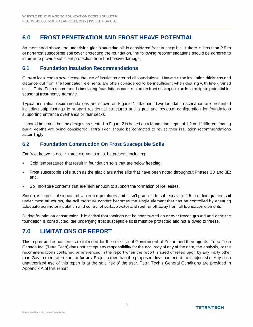
6.0 FROST PENETRATION AND FROST HEAVE POTENTIAL
As mentioned above, the underlying glaciolacustrine silt is considered frost-susceptible. If there is less than 2.5 m
of non-frost susceptible soil cover protecting the foundation, the following recommendations should be adhered to
in order to provide sufficient protection from frost heave damage.
6.1 Foundation Insulation Recommendations
Current local codes now dictate the use of insulation around all foundations. However, the insulation thickness and
distance out from the foundation elements are often considered to be insufficient when dealing with fine grained
soils. Tetra Tech recommends insulating foundations constructed on frost susceptible soils to mitigate potential for
seasonal frost-heave damage.
Typical insulation recommendations are shown on Figure 2, attached. Two foundation scenarios are presented
including strip footings to support residential structures and a pad and pedestal configuration for foundations
supporting entrance overhangs or rear decks.
It should be noted that the designs presented in Figure 2 is based on a foundation depth of 1.2 m. If different footing
burial depths are being considered, Tetra Tech should be contacted to revise their insulation recommendations
accordingly.
6.2 Foundation Construction On Frost Susceptible Soils
For frost heave to occur, three elements must be present, including:
Cold temperatures that result in foundation soils that are below freezing;
Frost susceptible soils such as the glaciolacustrine silts that have been noted throughout Phases 3D and 3E;and,
Soil moisture contents that are high enough to support the formation of ice lenses.
Since it is impossible to control winter temperatures and it isn’t practical to sub-excavate 2.5 m of fine grained soil
under most structures, the soil moisture content becomes the single element that can be controlled by ensuring
adequate perimeter insulation and control of surface water and roof runoff away from all foundation elements.
During foundation construction, it is critical that footings not be constructed on or over frozen ground and once the
foundation is constructed, the underlying frost susceptible soils must be protected and not allowed to freeze.
7.0 LIMITATIONS OF REPORT
This report and its contents are intended for the sole use of Government of Yukon and their agents. Tetra Tech
Canada Inc. (Tetra Tech) does not accept any responsibility for the accuracy of any of the data, the analysis, or the
recommendations contained or referenced in the report when the report is used or relied upon by any Party other
than Government of Yukon, or for any Project other than the proposed development at the subject site. Any such
unauthorized use of this report is at the sole risk of the user. Tetra Tech’s General Conditions are provided in
Appendix A of this report.

WHISTLE BEND PHASE 3C FOUNDATION DESIGN BULLETIN
FILE: W14103567-18.004 | APRIL 11, 2017 | ISSUED FOR USE
5
Whistle Bend Ph 3C Foundation Design Bulletin
8.0 CLOSURE
We trust this report meets your present requirements. If you have any questions or comments, please contact the
undersigned.
Respectively Submitted,
Tetra Tech Canada Inc.
Myles Plaunt, CET
Senior Engineering Technologist, Arctic Region
Direct Line: 867.668.9217
Chad Cowan, P.Eng.
Geotechnical Manager – Yukon, Arctic Region
Direct Line: 867.668.9214
Attachments: Figure 1 – 3C: Site Plan Showing Existing Borehole and Testpit Locations
Figure 2: Foundation Insulation Details
Appendix A: Testhole Logs Specific To Phase 3C
Appendix B: Tetra Tech’s General Conditions

WHISTLE BEND PHASE 3C FOUNDATION DESIGN BULLETIN
FILE: W14103567-18.004 | APRIL 11, 2017 | ISSUED FOR USE
Whistle Bend Ph 3C Foundation Design Bulletin
FIGURES
Figure 1 Site Plan Showing Phase 3C Borehole and Testpit Locations
Figure 2 Foundation Insulation Details

CASCA BOULEVARD
ELDORADO ROAD
KENO WAY
CASCA BOULEVARD
W14101171-BH15
W14101171-BH14
W14101171-BH13
W14101171-BH11
W14101372-TP03
W14101372-TP12
W14101372-TP15
W14101372-TP16
W14101372-TP17
W14101372-TP18
W14101372-TP19
W14101372-TP20
W14101372-BH01
W14101372-BH02
W14103526-TP03
W14101545.001-TP02
W14101500-BH02
W14101545.001-TP03
TP01
TP02TP03
TP04TP05
TP06
TP07
TP08
TP09
TP10
TP11
TP12
PHAS
E 3C
LIM
ITS
TP15
TP13
TP14
141
142
151
152
160
161
166
167
168
GREE
NBEL
T
GREE
NBEL
T
GREENBELT
GREE
NBEL
T
GREE
NBEL
T
305
298
290
282
139
140
171
170
169
165
164
163
162
143
144
145
146
147
148
149
150
153
154
155
156
157
291
292
293
294
295
297
296
283285286
288
299
300
301
302
303
304
281
280284
287
GREENBELT
160
LOT 413 (GREENBELT)
412
411410
409
408
407
541 (PARK)
535 (
PUL)
536 (
PUL)
201 (Greenbelt)
200 (
GREE
NBEL
T)
1234567
8
9
10
11
12
13
14
15
16
17
18
19
20
21
22
23
24
25
26
27
2829
48 49
50
51
52
53
54
55
56
57
58
59
6061
62
194
195 193
182
183 184
185
186
187
188
189
190
191
192
202 (
Gree
nbelt
)
477
476
482
475
481
480
479
478
418
417
416
415
414
413
412
411
410
409
408
52552
4523
529
522
528
521
527
526
485
486487
488489
490
483
491
484
437
456 455
430
454
539(PARKING)
443444445446447
431
432
540(PARKING)
448
436
433
355 (
PUL)
449
450451452453
420
421
422
423
424
425
426
427
428
538 (INSTITUTIONAL)
542 (PARK)
429
438
440442 441 439
435
347 (
PUL)
534
513
512
518
511
510
517
509
516
508
515
507
514
519
434
501
494
502
495
503
496
504
497
505
498
506
499
500
546 (GREENBELT)
533
520
493
545 (GREENBELT)
470 471 472 473
464
465 466 467 468 469
457
548 (
GREE
NBEL
T)
544 (
GREE
NBEL
T)
474
346 (PUL)
547 (
GREE
NBEL
T)
492
Q:\W
hitehorse\D
ata\0201draw
ings\W
hitehorse\W
141\W
14103567-18 W
histle B
end E
xisting G
eo C
om
pilation\W
14103567-18.004 P
hase 3C
F
ig.1-R
0.dw
g [F
IG
UR
E 1 - 3C
] M
arch 17, 2017 - 3:58:36 pm
(B
Y: B
UC
HA
N, C
AM
ER
ON
)
CLIENT
PROJECT NO. DWN CKD REV
OFFICE DATE
Figure 1 - 3C
March 17, 2017EBA-WHSE
0MCPCBW14103567-18.004
PHASE 3C GEOTECHNICAL EVALUATIONWHISTLE BEND - WHITEHORSE, YUKON
SITE PLAN SHOWINGBOREHOLE AND TESTPIT LOCATIONS
0 50m
Scale: 1:1,250 @ 22"x34"
LEGEND
- BOREHOLE LOCATION
- MONITORING WELL LOCATION
- HISTORICAL TESTPIT LOCATION
- TESTPIT LOCATION (DECEMBER 2016 TO MARCH 2017)

1
1
1.2 m
1.2 m
2.4 m
200 mm THICK
INSULATION AT CORNERS
EXTERIOR WALL
PLANN.T.S.
100 mm THICK INSULATION
ALONG PERIMETER OF
BUILDING
200 mm THICK INSULATION
IN FRONT OF ENTRANCES
GROUND SURFACE
100 mm THICK
INSULATION 1200 mm WIDE
75 mm THICK PROTECTIVE
SAND LAYER (SEE NOTES)
300 mm MINIMUM COVER
OVER INSULATION
SLO
PE
GR
OU
ND
SU
RF
AC
E
100 to 200 mm (VARIES) THICK
INSULATION 1200 mm WIDE
75 mm THICK
PROTECTIVE SAND LAYER
300 mm MINIMUM COVER
OVER INSULATION
FLASHING
INSIDE
FLOOR
SECTION - STRIP FOOTINGN.T.S.
PAD AND PEDESTAL DETAILN.T.S.
1.2 m FROM EDGE OF PADIN ALL DIRECTIONS
CLIENT
PROJECT NO. DWN CKD REV
OFFICE DATE
Q:\W
hite
ho
rse
\D
ata
\0
20
1d
ra
win
gs\W
hite
ho
rse
\W
14
1\W
14
10
35
67
-1
8 W
histle
B
en
d E
xistin
g G
eo
C
om
pila
tio
n\W
14
10
35
67
-1
8.0
04
P
ha
se
3
A F
ig
.1
-R
0.d
wg [F
IG
UR
E 2] M
arch
2
9, 2
01
7 - 1
:5
7:5
9 p
m (B
Y: B
UC
HA
N, C
AM
ER
ON
)
Figure 2
January 25, 2016EBA-WHSE
0MCPCBW14103567-18.004
PHASE 3 GEOTECHNICAL EVALUATIONWHISTLE BEND - WHITEHORSE, YUKON
FOUNDATION INSULATION DETAILS
NOTES :
- THE INSULATION (DOW CHEMICAL HI SERIES STYROFOAM OR POLYURETHANE OR APPROVED EQUIVALENT) SHOULD BE MOISTURE RESISTANT AND SUITABLE FOR BURIAL UNDER VEHICULAR TRAFFIC AREAS.
- A MINIMUM BEDDING THICKNESS OF 75 mm OF FINE TO MEDIUM GRAINED SAND SHOULD BE PLACED ABOVE AND BELOW THE INSULATION FOR PROTECTION.
- THIS PLAN IS NOT TO SCALE

WHISTLE BEND PHASE 3C FOUNDATION DESIGN BULLETIN
FILE: W14103567-18.004 | APRIL 11, 2017 | ISSUED FOR USE
Whistle Bend Ph 3C Foundation Design Bulletin
APPENDIX APHASE 3C TESTHOLE LOGS

TERMS USED ON BOREHOLE LOGS
2030-11.cdr
Information presented herein is for the sole use of EBA's client for this project. EBA is not responsible for, nor can be held liable, for use made of this
Field Report by any other party, with or without the knowledge of EBA. The contents of this Field Report incorporate and are subject to EBA's report
for this project and it's General Conditions, a copy of which are included in the engineering report and can be provided upon request.
TERMS DESCRIBING CONSISTENCY OR CONDITION
COARSE GRAINED SOILS (major portion retained on 0.075mm sieve): Includes (1) clean gravels and sands, and (2) silty or clayey gravels and sands. Condition is rated according to relative density, as inferred from laboratory or in situ tests.
FINE GRAINED SOILS (major portion passing 0.075mm sieve): Includes (1) inorganic and organic silts and clays, (2) gravelly, sandy, or silty clays, and (3) clayey silts. Consistency is rated according to shearing strength, as estimated from laboratory or in situ tests.
DESCRIPTIVE TERM
Very LooseLoose
CompactDense
Very Dense
RELATIVE DENSITY
0 TO 20%20 TO 40%40 TO 75%75 TO 90%90 TO 100%
N (blows per 0.3m)
0 to 44 to 1010 to 3030 to 50
greater than 50
The number of blows, N, on a 51mm O.D. split spoon sampler of a 63.5kg weight falling 0.76m, required to drive the sampler a distance of 0.3m from 0.15m to 0.45m.
NOTE: Slickensided and fissured clays may have lower unconfined compressive strengths than shown above, because of planes of weakness or cracks in the soil.
DESCRIPTIVE TERM
Very SoftSoftFirmStiff
Very StiffHard
UNCONFINED COMPRESSIVE STRENGTH (KPA)
Less than 2525 to 5050 to 100100 to 200200 to 400
Greater than 400
GENERAL DESCRIPTIVE TERMS
Slickensided - having inclined planes of weakness that are slick and glossy in appearance.Fissured - containing shrinkage cracks, frequently filled with fine sand or silt; usually more or less vertical.Laminated - composed of thin layers of varying colour and texture.Interbedded - composed of alternate layers of different soil types.Calcareous - containing appreciable quantities of calcium carbonate.;Well graded - having wide range in grain sizes and substantial amounts of intermediate particle sizes.Poorly graded - predominantly of one grain size, or having a range of sizes with some intermediate size missing.
______________________________________________________________________________
______________________________________________________________________________

Modified Unified Soil Classification_Arctic_Nov 2011.cdr
50%
or
more
of co
ars
e fra
ctio
nre
tain
ed o
n N
o. 4 s
ieve
Well-graded gravels and gravel-sand mixtures, little or no fines
TYPICAL DESCRIPTION
Poorly-graded gravels and gravel-sand mixtures, little or no fines
Silty gravels, gravel-sand-siltmixtures
Clayey gravels, gravel-sand-claymixtures
Well-graded sands and gravellysands, little or no fines
Poorly-graded sands and gravellysands, little or no fines
Silty sands, sand-silt mixtures
Clayey sands, sand-clay mixtures
Inorganic silts, very fine sands, rockflour, silty or clayey fine sands ofslight plasticity
Inorganic silts, micaceous ordiatomaceous fine sands or silts,elastic silts
Inorganic clays of low plasticity,gravelly clays, sandy clays, siltyclays, lean clays
Inorganic clay of mediumplasticity, silty clays
Inorganic clay of high plasticity,fat clays
Organic silts and organic siltyclays of low plasticity
Organic clays of medium to highplasticity
Peat, muck and other highly organicsoils
LABORATORY CLASSIFICATION CRITERIA
C = D / DU 60 10Greater than 4
Between 1 and 3C = C
2(D )30
D x D10 60
Atterberg limits plot below ‘A’ line orplasticity index less than 4
Atterberg limits plot above ‘A’ line andplasticity index greater than 7
D x D10 60
C = D / DU 60 10Greater than 6
Between 1 and 3C = C
2(D )30
Atterberg limits plottingin hatched area areborderline classificationsrequiring use of dualsymbols
Atterberg limits plot above ‘A’ line andplasticity index less than 4
Atterberg limits plot above ‘A’ line andplasticity index greater than 7
Atterberg limits plottingin hatched area areborderline classificationsrequiring use of dualsymbols
Cla
ssif
icati
on
on
basis
of
perc
en
tag
e o
f fi
nes
Less
than 5
% p
ass
75 µ
m s
ieve
More
than 1
2%
pass
75 µ
m s
ieve
5%
to 1
2%
pass
75 µ
m s
ieve
GW
, G
P, S
W, S
PG
M, G
C, S
M, S
CB
ord
erlin
e c
lass
ifica
tion
requirin
g u
se o
f dual s
ymbols
* Based on the material passing the 75 mm sieve
ASTM Designation D 2487, for identification procedure see D 2488 USC as modifiedby PFRA
60
50
40
30
20
1074
00 10 20 30 40 50 60 70 80 90 100
LIQUID LIMIT
PL
AS
TIC
ITY
IN
DE
X
ML or OL
MH or OH
ClCL
CL-ML
CH
‘A’ line
PLASTICITY CHART
For classification of fine-grainedsoils and fine fraction of coarse-grained soils
Equation of ‘A’ line: Pl = 0.73(LL-20)
Not meeting both criteria for GW
Not meeting both criteria for SW
MAJOR DIVISION
CO
AR
SE
- G
RA
INE
D S
OIL
S
More
than 5
0%
reta
ined o
n N
o. 75 µ
m s
ieve
*
GR
AV
EL
SS
AN
DS
More
than 50%
of co
ars
efr
act
ion p
ass
es
No. 4 s
ieve
SA
ND
SW
ITH
FIN
ES
CLE
AN
SA
ND
SG
RA
VE
LS
WIT
HF
INE
SC
LE
AN
GR
AV
ELS
HIGHLY ORGANIC SOILS
FIN
E-G
RA
INE
D S
OIL
S (
by b
eh
avio
r)
50%
or
more
pass
es
75 µ
m s
ieve
*
Ab
ove
“A
” lin
e o
np
last
icity
ch
art
ne
glig
ible
org
an
ic c
on
ten
t
Liq
uid
lim
it
>5
0
30
-50
<
30
CL
AY
S
Liq
uid
lim
it
>5
0
<5
0
OR
GA
NIC
SIL
TS
AN
D C
LA
YS
Liq
uid
lim
it
>5
0
<5
0
SIL
TS
GROUPSYMBOL
GW
GP
GM
GC
SW
SP
SM
SC
PT
ML
MH
CL
Cl
CH
OL
OH
MODIFIED UNIFIED SOIL CLASSIFICATION
VISIBLE ICE LESS THAN 50% BY VOLUME
VISIBLE ICE GREATER THAN 50% BY VOLUME
ICE NOT VISIBLE
Dual symbols are used to indicate borderline or mixedice classifications.
Visual estimates of ice contents indicated on borehole logs ± 5%
This system of ground ice description has been modified fromNRC Technical Memo 79, Guide to the Field Description ofPermafrost for Engineering Purposes.
1.
2.
3.
NOTES:
LEGEND: Soil Ice
GROUND ICE DESCRIPTION
SUBGROUP DESCRIPTIONSYMBOLGROUP
SYMBOL
Poorly-bonded or friable
No excess ice, well-bonded
Excess ice, well-bonded
Nf
Nbn
Nbe
N
Individual ice crystals or inclusions
SUBGROUP DESCRIPTIONSYMBOLGROUP
SYMBOL
Ice coatings on particles
Random or irregularly orientedice formations
Stratified or distinctly orientedice formations
Vx
Vc
Vr
Vs
V
Ice with soil inclusions
Ice without soil inclusions(greater than 25 mm thick
ICE +Soil Type
ICE
ICE

ORGANICS - black, (150 mm thick)
SILT (GLACIOLACUSTRINE) - trace to some clay, olive brown
- moist
END OF TESTPIT (1.5 metres)
Exc
avat
ed
Seasonally frozen
Unfrozen
SoilDescription
NORTHERN W14103567-18.GPJ EBA.GDT 17/01/24
Met
hod
Completion Depth: 1.5 m
Start Date: 2016 December 05
Completion Date: 2016 December 05
Page 1 of 1
Government of Yukon -Community Services
Project: Geotechnical Evaluation Services
Location: Whistle Bend Subdivision - Phase 3
Whitehorse, Yukon
Contractor: Arctic Backhoe Services
Drilling Rig Type: CAT Rubber Tired Backhoe
Logged By: MCP
Reviewed By: CPC
Testpit No: TP04Project No: W14103567-18.004
Ground Elev: 676.5 m
UTM: 494362 E; 6738086 N; Z 8
0
3
Dep
th(m
)
1
2
Elev
atio
n(m
)
676
675
674
Moi
stur
e C
onte
nt (%
)
PlasticLimit
MoistureContent
LiquidLimit
20 40 60 80
Ground IceDescription

ORGANICS - thin veneer left after stripping, black, (50 mm thick)SILT (GLACIOLACUSTRINE) - trace to some clay, olive brown
- moist
END OF TESTPIT (1.5 metres)
Exc
avat
ed
Seasonally frozen
Unfrozen
SoilDescription
NORTHERN W14103567-18.GPJ EBA.GDT 17/01/24
Met
hod
Completion Depth: 1.5 m
Start Date: 2016 December 05
Completion Date: 2016 December 05
Page 1 of 1
Government of Yukon -Community Services
Project: Geotechnical Evaluation Services
Location: Whistle Bend Subdivision - Phase 3
Whitehorse, Yukon
Contractor: Arctic Backhoe Services
Drilling Rig Type: CAT Rubber Tired Backhoe
Logged By: MCP
Reviewed By: CPC
Testpit No: TP09Project No: W14103567-18.004
Ground Elev: 677 m
UTM: 494255 E; 6738305 N; Z 8
0
3
Dep
th(m
)
1
2
Elev
atio
n(m
)
677
676
675
674
Moi
stur
e C
onte
nt (%
)
PlasticLimit
MoistureContent
LiquidLimit
20 40 60 80
Ground IceDescription
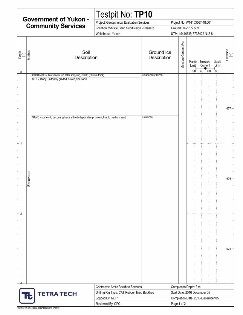
ORGANICS - thin veneer left after stripping, black, (50 mm thick)SILT - sandy, uniformly graded, brown, fine sand
SAND - some silt, becoming trace silt with depth, damp, brown, fine to medium sand
Exc
avat
ed
Seasonally frozen
Unfrozen
SoilDescription
NORTHERN W14103567-18.GPJ EBA.GDT 17/01/24
Met
hod
Completion Depth: 3 m
Start Date: 2016 December 05
Completion Date: 2016 December 05
Page 1 of 2
Government of Yukon -Community Services
Project: Geotechnical Evaluation Services
Location: Whistle Bend Subdivision - Phase 3
Whitehorse, Yukon
Contractor: Arctic Backhoe Services
Drilling Rig Type: CAT Rubber Tired Backhoe
Logged By: MCP
Reviewed By: CPC
Testpit No: TP10Project No: W14103567-18.004
Ground Elev: 677.5 m
UTM: 494105 E; 6738422 N; Z 8
0
3
Dep
th(m
)
1
2
Elev
atio
n(m
)
677
676
675
Moi
stur
e C
onte
nt (%
)
PlasticLimit
MoistureContent
LiquidLimit
20 40 60 80
Ground IceDescription
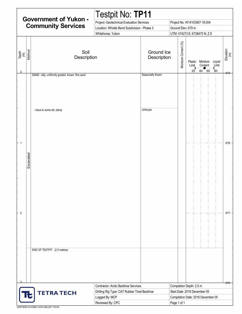
SAND - silty, uniformly graded, brown, fine sand
- trace to some silt, damp
END OF TESTPIT (2.5 metres)
Exc
avat
ed
Seasonally frozen
Unfrozen
SoilDescription
NORTHERN W14103567-18.GPJ EBA.GDT 17/01/24
Met
hod
Completion Depth: 2.5 m
Start Date: 2016 December 05
Completion Date: 2016 December 05
Page 1 of 1
Government of Yukon -Community Services
Project: Geotechnical Evaluation Services
Location: Whistle Bend Subdivision - Phase 3
Whitehorse, Yukon
Contractor: Arctic Backhoe Services
Drilling Rig Type: CAT Rubber Tired Backhoe
Logged By: MCP
Reviewed By: CPC
Testpit No: TP11Project No: W14103567-18.004
Ground Elev: 679 m
UTM: 474273 E; 6738470 N; Z 8
0
3
Dep
th(m
)
1
2
Elev
atio
n(m
)
679
678
677
676
Moi
stur
e C
onte
nt (%
)
PlasticLimit
MoistureContent
LiquidLimit
20 40 60 80
Ground IceDescription

ORGANICS - thin veneer left after stripping, black, (50 mm thick)SAND - some silt to silty, brown, fine sand
- damp
- cleaner, fine to medium sand
END OF TESTPIT (2.5 metres)
Exc
avat
ed
Seasonally frozen
Unfrozen
SoilDescription
NORTHERN W14103567-18.GPJ EBA.GDT 17/01/24
Met
hod
Completion Depth: 2.5 m
Start Date: 2016 December 05
Completion Date: 2016 December 05
Page 1 of 1
Government of Yukon -Community Services
Project: Geotechnical Evaluation Services
Location: Whistle Bend Subdivision - Phase 3
Whitehorse, Yukon
Contractor: Arctic Backhoe Services
Drilling Rig Type: CAT Rubber Tired Backhoe
Logged By: MCP
Reviewed By: CPC
Testpit No: TP12Project No: W14103567-18.004
Ground Elev: 678.5 m
UTM: 494366 E; 6738379 N; Z 8
0
3
Dep
th(m
)
1
2
Elev
atio
n(m
)
678
677
676
Moi
stur
e C
onte
nt (%
)
PlasticLimit
MoistureContent
LiquidLimit
20 40 60 80
Ground IceDescription

SAND - some silt to silty, uniformly graded, light brown, fine sand
- trace of silt
- sloughing badly below 2.00 metres
SILT (GLACIOLACUSTRINE) - trace to some clay, moist, olive brown
END OF TESTPIT (5.00 metres)
Exc
avat
or
Seasonally frozen
Unfrozen
SoilDescription
NORTHERN W14103567-18.004.GPJ EBA.GDT 17/3/17
Met
hod
Completion Depth: 5 m
Start Date: 2017 March 15
Completion Date: 2017 March 15
Page 1 of 1
Government of Yukon -Community Services
Project: Geotechnical Evaluation Services
Location: Whistle Bend Subdivision - Phase 3C
Whitehorse, Yukon
Contractor: Castle Rock Ent.
Drilling Rig Type: Linkbelt 330 Tracked
Logged By: MCP
Reviewed By: CPC
Testpit No: TP13Project No: W14103567-18.004
Ground Elev: 680 m
UTM: 494310 E; 6738435 N; Z 8
0
7.5
Dep
th(m
)
1
2
3
4
5
6
7
Elev
atio
n(m
)
680
679
678
677
676
675
674
673
Moi
stur
e C
onte
nt (%
)
PlasticLimit
MoistureContent
LiquidLimit
20 40 60 80
Ground IceDescription
SAND - some silt to silty, uniformly graded, light brown, fine sand
SILT (GLACIOLACUSTRINE) - trace to some clay, olive brown
END OF TESTPIT (1.20 metres)
Exc
avat
or
Seasonally frozen
SoilDescription
NORTHERN W14103567-18.004.GPJ EBA.GDT 17/3/17
Met
hod
Completion Depth: 1.2 m
Start Date: 2017 March 15
Completion Date: 2017 March 15
Page 1 of 1
Government of Yukon -Community Services
Project: Geotechnical Evaluation Services
Location: Whistle Bend Subdivision - Phase 3C
Whitehorse, Yukon
Contractor: Castle Rock Ent.
Drilling Rig Type: Linkbelt 330 Tracked
Logged By: MCP
Reviewed By: CPC
Testpit No: TP14Project No: W14103567-18.004
Ground Elev: 677.5 m
UTM: 494420 E; 6738450 N; Z 8
0
7.5
Dep
th(m
)
1
2
3
4
5
6
7
Elev
atio
n(m
)
677
676
675
674
673
672
671
670
Moi
stur
e C
onte
nt (%
)
PlasticLimit
MoistureContent
LiquidLimit
20 40 60 80
Ground IceDescription

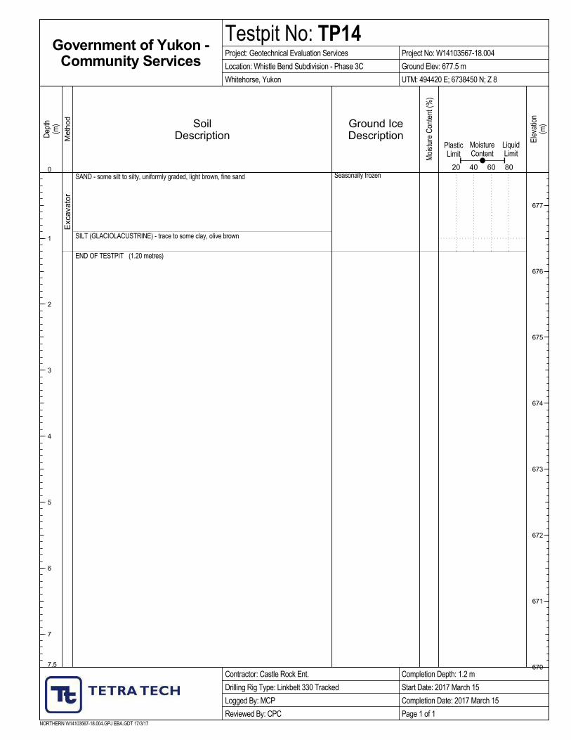
SAND - some silt to silty, uniformly graded, light brown, fine sand
- cleaner, medium brown, medium sand
- sloughing badly below 2.00 metres
SILT (GLACIOLACUSTRINE) - trace to some clay, moist, olive brown
END OF TESTPIT (4.00 metres)
Exc
avat
or
Seasonally frozen
Unfrozen
SoilDescription
NORTHERN W14103567-18.004.GPJ EBA.GDT 17/3/17
Met
hod
Completion Depth: 4 m
Start Date: 2017 March 15
Completion Date: 2017 March 15
Page 1 of 1
Government of Yukon -Community Services
Project: Geotechnical Evaluation Services
Location: Whistle Bend Subdivision - Phase 3C
Whitehorse, Yukon
Contractor: Castle Rock Ent.
Drilling Rig Type: Linkbelt 330 Tracked
Logged By: MCP
Reviewed By: CPC
Testpit No: TP15Project No: W14103567-18.004
UTM: 494180 E; 6738510 N; Z 8
0 0
7.5
Dep
th(m
)
1
2
3
4
5
6
7
Dep
th(ft
)
1
2
3
4
5
6
7
8
9
10
11
12
13
14
15
16
17
18
19
20
21
22
23
24
Moi
stur
e C
onte
nt (%
)
PlasticLimit
MoistureContent
LiquidLimit
20 40 60 80
Ground IceDescription

1
2
3
4
5
ORGANIC ROOT MATERIAL - seasonally frozen, brown and blackSAND - silty, trace organics at upper interface, fine grained, uniform, damp below
seasonal frost, medium brown - sand becomes slightly coarser, trace silt, dry to damp, medium greyish brown
- trace to some gravel from 1.5 to 2.5 m
SILT - some clay, trace fine sand, damp, firm, light olive
- moisture content increases with depth, firm, becomes dark olive
- easy drilling throughout depth of borehole
END OF BOREHOLE @ 6.0 m
PEA GRAVELBENTONITE
LOGGED BY: MCPREVIEWED BY:DRAWING NO:
Geotechnical Evaluation
Whistle Bend Subdivision
Whitehorse, YT
10
SAMPLE TYPE
BACKFILL TYPE
WHITEHORSE ZONE8.GPJ EBA.GDT 16/11/22
1
2
3
4
5
6
7
8
9
SOILDESCRIPTION
DISTURBED SHELBY TUBEA-CASING CORE
SAM
PLE
NU
MBE
R
SAM
PLE
TYPE
NO RECOVERY SPT
5
10
15
20
25
30
Dep
th (m
)
SAND
COMPLETION DEPTH: 6mCOMPLETE: 08/12/10Page 1 of 1
0
33
Dep
th (f
t)
0
SLOUGH DRILL CUTTINGSGROUT
AECOM
Drilling Method: NODWELL Mounted CME 75
BOREHOLE NO: BH13
PROJECT: W14101171
SPT (N) 40
GROUND ICEDESCRIPTION
ANDCOMMENTS
BULK DENSITY (kg/m3) 1400
40 60 80
LIQUID
20
20
20 40 60
SILT (%)
GRAVEL (%) 20 40 60 80
80
20 40 60 80
20
60
40 60 80
SAND (%)
CLAY (%)
PLASTIC M.C.
80
1600 20001800

19
18
15
10
SA01
SA02
SA03
SA04
SA05
TEA GROUND COVER and ORGANIC ROOT MAT - damp, mediumbrown
SAND - silty, fine grained, uniform, damp, loose, medium brown
SILT - some fine sand, trace clay, damp, stiff, light olive
- smooth drilling
- thin lens of moist soil @ 3.0 m
- moisture content increases below 5.5 m, firm, darker olive in colour
END OF BOREHOLE @ 6.5 m
PEA GRAVELBENTONITE
LOGGED BY: MCPREVIEWED BY: CPCDRAWING NO:
Whistle Bend Subdivision
Detailed Geotechnical Design
Pumphouse, Whitehorse, YT
12
SAMPLE TYPE
BACKFILL TYPE
WHITEHORSE ZONE8.GPJ EBA.GDT 16/11/22
1
2
3
4
5
6
7
8
9
10
11
SPT
(N)
SOILDESCRIPTION
DISTURBED SHELBY TUBEA-CASING CORE
SAM
PLE
NU
MBE
R
SAM
PLE
TYPE
NO RECOVERY SPT
5
10
15
20
25
30
35
Dep
th (m
)
SAND
COMPLETION DEPTH: 6.5mCOMPLETE: 10/07/19Page 1 of 1
0
39
Dep
th (f
t)
0
SLOUGH DRILL CUTTINGSGROUT
CLIENT: Associated Engineering
DRILL: Nodwell Mounted CME 75
BOREHOLE NO: BH01
PROJECT: W14101372.002
SPT (N) 40
GROUND ICEDESCRIPTION
ANDCOMMENTS
BULK DENSITY (kg/m3) 1400
40 60 80
LIQUID
20
20
20 40 60
SILT (%)
GRAVEL (%) 20 40 60 80
80
20 40 60 80
20
60
40 60 80
SAND (%)
CLAY (%)
PLASTIC M.C.
80
1600 20001800
13
14
9
7
3
4
3
SA06
SA07
SA08
SA09
SA10
SA11
SA12
SA13
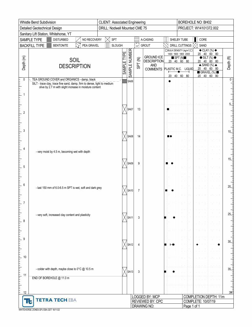
TEA GROUND COVER and ORGANICS - damp, blackSILT - trace clay, trace fine sand, damp, firm to dense, light to medium
olive by 2.7 m with slight increase in moisture content
- very moist by 4.5 m, becoming wet with depth
- last 150 mm of 6.0-6.5 m SPT is wet, soft and dark grey
- very soft, increased clay content and plasticity
- colder with depth, maybe close to 0°C @ 10.5 m
END OF BOREHOLE @ 11.0 m
PEA GRAVELBENTONITE
LOGGED BY: MCPREVIEWED BY: CPCDRAWING NO:
Whistle Bend Subdivision
Detailed Geotechnical Design
Sanitary Lift Station, Whitehorse, YT
12
SAMPLE TYPE
BACKFILL TYPE
WHITEHORSE ZONE8.GPJ EBA.GDT 16/11/22
1
2
3
4
5
6
7
8
9
10
11
SPT
(N)
SOILDESCRIPTION
DISTURBED SHELBY TUBEA-CASING CORE
SAM
PLE
NU
MBE
R
SAM
PLE
TYPE
NO RECOVERY SPT
5
10
15
20
25
30
35
Dep
th (m
)
SAND
COMPLETION DEPTH: 11mCOMPLETE: 10/07/19Page 1 of 1
0
39
Dep
th (f
t)
0
SLOUGH DRILL CUTTINGSGROUT
CLIENT: Associated Engineering
DRILL: Nodwell Mounted CME 75
BOREHOLE NO: BH02
PROJECT: W14101372.002
SPT (N) 40
GROUND ICEDESCRIPTION
ANDCOMMENTS
BULK DENSITY (kg/m3) 1400
40 60 80
LIQUID
20
20
20 40 60
SILT (%)
GRAVEL (%) 20 40 60 80
80
20 40 60 80
20
60
40 60 80
SAND (%)
CLAY (%)
PLASTIC M.C.
80
1600 20001800

ORGANIC ROOT MAT - seasonally frozen, black
SAND - some silt to silty to 0.8 m, cleaner with trace of silt from 0.8 m to 1.2 m,seasonally frozen to 0.3 m, medium brown
SILT (GLACIOLACUSTRINE) - trace clay, trace fine sand, damp to moist, medium olive
END OF TESTPIT @ 2.0 m
NOTE: Testpit excavated at intersection of Casca Blvd (north leg) at the sanitary forcemain crossing
PEA GRAVELBENTONITE
LOGGED BY: MCPREVIEWED BY: CPCDRAWING NO:
Whistle Bend Subdivision
Detailed Geotechnical Design
Casca & Phases I and II, Whitehorse, YT
3
SAMPLE TYPE
BACKFILL TYPE
WHITEHORSE ZONE8.GPJ EBA.GDT 16/11/22
1
2
SOILDESCRIPTION
DISTURBED SHELBY TUBEA-CASING CORE
SAM
PLE
TYPE
NO RECOVERY SPT
5
Dep
th (m
)
SAND
COMPLETION DEPTH: 2mCOMPLETE: 10/10/18Page 1 of 1
0
10
Dep
th (f
t)
0
SLOUGH DRILL CUTTINGSGROUT
CLIENT: Associated Engineering
EXCAVATOR: Komatsu Rubber Tired Backhoe
TESTPIT NO: TP16
PROJECT: W14101372.002
SPT (N) 40
GROUND ICEDESCRIPTION
ANDCOMMENTS
BULK DENSITY (kg/m3) 1400
40 60 80
LIQUID
20
20
20 40 60
SILT (%)
GRAVEL (%) 20 40 60 80
80
20 40 60 80
20
60
40 60 80
SAND (%)
CLAY (%)
PLASTIC M.C.
80
1600 20001800

ORGANIC ROOT MAT - seasonally frozen, black
SAND - silty to some silt to 0.5 m, becomes cleaner with trace silt below 0.5 m, damp,medium to dark brown at 0.5 m
SILT (GLACIOLACUSTRINE) - trace clay, trace fine sand, damp to moist, medium olive
END OF TESTPIT @ 2.0 m
NOTE: Testpit excavated near north end of Casca Blvd
PEA GRAVELBENTONITE
LOGGED BY: MCPREVIEWED BY: CPCDRAWING NO:
Whistle Bend Subdivision
Detailed Geotechnical Design
Casca & Phases I and II, Whitehorse, YT
3
SAMPLE TYPE
BACKFILL TYPE
WHITEHORSE ZONE8.GPJ EBA.GDT 16/11/22
1
2
SOILDESCRIPTION
DISTURBED SHELBY TUBEA-CASING CORE
SAM
PLE
TYPE
NO RECOVERY SPT
5
Dep
th (m
)
SAND
COMPLETION DEPTH: 2mCOMPLETE: 10/10/18Page 1 of 1
0
10
Dep
th (f
t)
0
SLOUGH DRILL CUTTINGSGROUT
CLIENT: Associated Engineering
EXCAVATOR: Komatsu Rubber Tired Backhoe
TESTPIT NO: TP17
PROJECT: W14101372.002
SPT (N) 40
GROUND ICEDESCRIPTION
ANDCOMMENTS
BULK DENSITY (kg/m3) 1400
40 60 80
LIQUID
20
20
20 40 60
SILT (%)
GRAVEL (%) 20 40 60 80
80
20 40 60 80
20
60
40 60 80
SAND (%)
CLAY (%)
PLASTIC M.C.
80
1600 20001800

WHISTLE BEND PHASE 3C FOUNDATION DESIGN BULLETIN
FILE: W14103567-18.004 | APRIL 11, 2017 | ISSUED FOR USE
Whistle Bend Ph 3C Foundation Design Bulletin
APPENDIX BTETRA TECH’S GENERAL CONDITIONS

1
GENERAL CONDITIONS
GEOTECHNICAL REPORT – YUKON GOVERNMENT
This report incorporates and is subject to these “General Conditions”.
1.1 USE OF REPORT AND OWNERSHIP
This geotechnical report pertains to a specific site, a specific development and a specific scope of work. It is not applicable to any other sites nor should it be relied upon for types of development other than that to which it refers. Any variation from the site or development would necessitate a supplementary geotechnical assessment.
This report and the recommendations contained in it are intended for the sole use of TETRA TECH’s Client, the Yukon Government. TETRA TECH does not accept any responsibility for the accuracy of any of the data, the analyses or the recommendations contained or referenced in the report when the report is used or relied upon by any party other than TETRA TECH’s Client unless otherwise authorized in writing by TETRA TECH. Any unauthorized use of the report is at the sole risk of the user.
This report is subject to copyright and shall not be reproduced either wholly or in part without the prior, written permission of the Yukon Government, the Client, or TETRA TECH. It is acknowledged that the Yukon Government, the Client, may reproduce the report freely for internal usage.
1.2 ALTERNATE REPORT FORMAT
Where TETRA TECH submits both electronic file and hard copy versions of reports, drawings and other project-related documents and deliverables (collectively termed TETRA TECH’s instruments of professional service), only the signed and/or sealed versions shall be considered final and legally binding. The original signed and/or sealed version archived by TETRA TECH shall be deemed to be the original for the Project.
Both electronic file and hard copy versions of TETRA TECH’s instruments of professional service shall not, under any circumstances, no matter who owns or uses them, be altered by any party except TETRA TECH. TETRA TECH’s instruments of professional service will be used only and exactly as submitted by TETRA TECH.
Electronic files submitted by TETRA TECH have been prepared and submitted using specific software and hardware systems. TETRA TECH makes no representation about the compatibility of these files with the Client’s current or future software and hardware systems.
1.3 ENVIRONMENTAL AND REGULATORY ISSUES
Unless stipulated in the report, TETRA TECH has not been retained to investigate, address or consider and has not investigated, addressed or considered any environmental or regulatory issues associated with development on the subject site.
1.4 NATURE AND EXACTNESS OF SOIL AND ROCK DESCRIPTIONS
Classification and identification of soils and rocks are based upon commonly accepted systems and methods employed in professional geotechnical practice. This report contains descriptions of the systems and methods used. Where deviations from the system or method prevail, they are specifically mentioned.
Classification and identification of geological units are judgmental in nature as to both type and condition. TETRA TECH does not warrant conditions represented herein as exact, but infers accuracy only to the extent that is common in practice.
Where subsurface conditions encountered during development are different from those described in this report, qualified geotechnical personnel should revisit the site and review recommendations in light of the actual conditions encountered.
1.5 LOGS OF TESTHOLES
The testhole logs are a compilation of conditions and classification of soils and rocks as obtained from field observations and laboratory testing of selected samples. Soil and rock zones have been interpreted. Change from one geological zone to the other, indicated on the logs as a distinct line, can be, in fact, transitional. The extent of transition is interpretive. Any circumstance which requires precise definition of soil or rock zone transition elevations may require further investigation and review.
1.6 STRATIGRAPHIC AND GEOLOGICAL INFORMATION
The stratigraphic and geological information indicated on drawings contained in this report are inferred from logs of test holes and/or soil/rock exposures. Stratigraphy is known only at the locations of the test hole or exposure. Actual geology and stratigraphy between test holes and/or exposures may vary from that shown on these drawings. Natural variations in geological conditions are inherent and are a function of the historic environment. TETRA TECH does not represent the conditions illustrated as exact but recognizes that variations will exist. Where knowledge of more precise locations of geological units is necessary, additional investigation and review may be necessary.

General Conditions GEOTECHNICAL REPORT – YUKON GOVERNMENT
2
1.7 PROTECTION OF EXPOSED GROUND
Excavation and construction operations expose geological materials to climatic elements (freeze/thaw, wet/dry) and/or mechanical disturbance which can cause severe deterioration. Unless otherwise specifically indicated in this report, the walls and floors of excavations must be protected from the elements, particularly moisture, desiccation, frost action and construction traffic.
1.8 SUPPORT OF ADJACENT GROUND AND STRUCTURES
Unless otherwise specifically advised, support of ground and structures adjacent to the anticipated construction and preservation of adjacent ground and structures from the adverse impact of construction activity is required.
1.9 INFLUENCE OF CONSTRUCTION ACTIVITY
There is a direct correlation between construction activity and structural performance of adjacent buildings and other installations. The influence of all anticipated construction activities should be considered by the contractor, owner, architect and prime engineer in consultation with a geotechnical engineer when the final design and construction techniques are known.
1.10 OBSERVATIONS DURING CONSTRUCTION
Because of the nature of geological deposits, the judgmental nature of geotechnical engineering, as well as the potential of adverse circumstances arising from construction activity, observations during site preparation, excavation and construction should be carried out by a geotechnical engineer. These observations may then serve as the basis for confirmation and/or alteration of geotechnical recommendations or design guidelines presented herein.
1.11 DRAINAGE SYSTEMS
Where temporary or permanent drainage systems are installed within or around a structure, the systems which will be installed must protect the structure from loss of ground due to internal erosion and must be designed so as to assure continued performance of the drains. Specific design detail of such systems should be developed or reviewed by the geotechnical engineer. Unless otherwise specified, it is a condition of this report that effective temporary and permanent drainage systems are required and that they must be considered in relation to project purpose and function.
1.12 BEARING CAPACITY
Design bearing capacities, loads and allowable stresses quoted in this report relate to a specific soil or rock type and condition. Construction activity and environmental circumstances can materially change the condition of soil or rock. The elevation at which a soil or rock type occurs is variable. It is a requirement of this report that structural elements be founded in and/or upon geological materials of the type and in the condition assumed. Sufficient observations should be made by qualified geotechnical personnel during construction to assure that the soil and/or rock conditions assumed in this report in fact exist at the site.
1.13 SAMPLES
TETRA TECH will retain all soil and rock samples for 30 days after this report is issued. Further storage or transfer of samples can be made at the Client’s expense upon written request, otherwise samples will be discarded.
1.14 INFORMATION PROVIDED TO TETRA TECH BY OTHERS
During the performance of the work and the preparation of the report, TETRA TECH may rely on information provided by persons other than the Client. While TETRA TECH endeavours to verify the accuracy of such information when instructed to do so by the Client, TETRA TECH accepts no responsibility for the accuracy or the reliability of such information which may affect the report.