Embed Size (px)
Citation preview

10 October 2002 1
ZAMBONIZippy Aerospace Module Broadcasting
Observed Not-so-bad Images
Fall Design Review
Harrington Hall, Room 218

10 October 2002 2
DesignTeam
Mechanical EngineeringJon FargoKatie KirchnerAndrea Mattern
Electrical EngineeringMike HoffmannJon LovsethChris SchmidtJason SentiWarren Wambsganss
Not-so-bad FacultyArnie JohnsonRichard SchultzWill SemkeChang-Hee Won

10 October 2002 3
UND Vision
1. Moored Balloon
2. Free Balloon
3. AEROCam
4. AgCam (ISS) & CubeSat
2000 2000-2001 2001-2002 2002-beyond

10 October 2002 4
What is a CubeSat
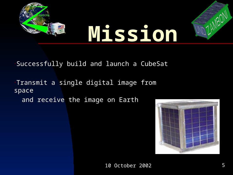
Size ~ 10 cm (4”) CubeMass ~ 1 kg
•Idea originated at Stanford University by Professor Robert Twiggs
•California Poly responsible for launch integration
10 October 2002 5
Mission•Successfully build and launch a CubeSat
•Transmit a single digital image from space and receive the image on Earth

10 October 2002 6
Goal•Orbit Earth for approximately 8 months
•Transmit numerous digital images to Earth
•Transmit health/status data to Earth
•Transmit data from a commercial/ government sponsored payload to Earth

10 October 2002 7
Launch•Expected early 2004 launch
•800 kilometer orbit
•Approximately $80,000
•Rent space for government/industry payload
•Alumni support: “Decameter for a Dollar” campaign

10 October 2002 8
System Overview
FullImageDigital
CameraMechanicalStructure
interfaces with allairborne subsystems
Microcontroller
Amateur Radio
and TNC
CameraControl
Data
Voltage
Current
TelemetryTelecommand
Ground Transceiver
Amateur Radio Operators
Operator
Ground Control
Computer
Mission Planning Software –
Satellite Tool Kit
ImagesData
ConsoleInputs
Ground ControlUniversity of North Dakota
ThumbnailImage
ZAMBONIHealth & Status
Sensors
Solar Cells
Charging Circuitry
Regulation
Power
Batteries
Health& Status
Data
PassiveAttitudeControl
(Rare-Earth magnet)
Telemetry
C&DH
Internet Communications
SponsoredScientificPayload
Watchdog Timer

10 October 2002 9
JonFargo

10 October 2002 10
DesignSpecs
Requirements•Mass not to exceed 2 kg•Center of mass within 2 cm of the geometric center•Structure Material: Aluminum 6061
Testing•Vibration qualification test•Thermal test•Vibration acceptance test•Integration
10 October 2002 11
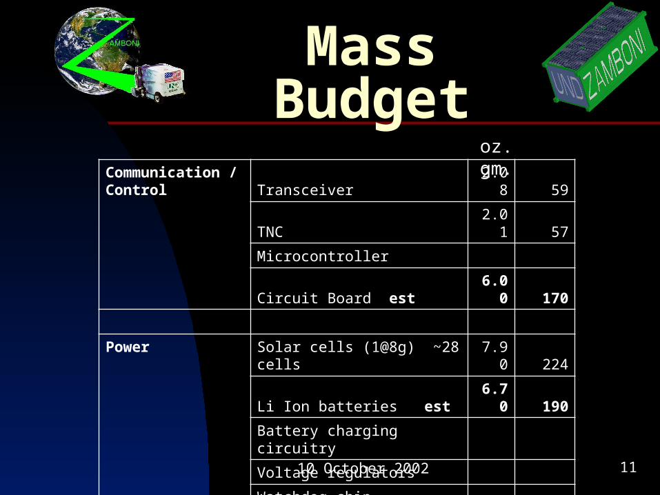
Mass Budget
Communication / Control
Transceiver 2.08 59
TNC 2.01 57
Microcontroller
Circuit Board est 6.00 170
Power Solar cells (1@8g) ~28 cells 7.90 224
Li Ion batteries est 6.70 190
Battery charging circuitry
Voltage regulators
Watchdog chip
Attitude Control Passive magnet 1.27 36
oz. gm.

10 October 2002 12
Mass Budget
Sensors Temperature sensors
Voltage sensors
Current sensors
2 Digital cameras w/o batteries or case (1@96g) 6.77 192
Structure Aluminum frame est. 17.64 500
Payload Allotted mass 10.58 300
20% Margin 14.11 400
Total 75.06 2128
Budgeted Mass 70.55 2000
% over/under budget 6.40% 6.40%

10 October 2002 13
SizeBudget
Major Components
cu. in. cu. cm.
Ham Radio 2.88 45
TNC 9.28 152.38
Li Ion Batteries 3.061 50.92
Digital Camera - x 2 26.62 432
Frame 118.64 2000
Payload – ¼ volume 29.66 500
Total Volume 41.841 680.3
Remaining Volume: 47.139 819.7
•Total volume available = 10 *10*20 cm = 2000 cm^3
•Total Volume Used = 680.3 cm^3
•66% Volume Remaining
•Does not include wires and other misc. connections

10 October 2002 14
P-Pod•Aluminum 7075-T6
•Spring Deployed
•Thermal line cutter actuator
•Railings
•Interface port (access CubeSat in deployer)

10 October 2002 15
Testpod
•Internal dimensions same as launcher tube
•Will accommodate double and triple cubes
•Designed and manufactured at UND

10 October 2002 16
Testpod•Launch condition testing
•Needs two mounting plates
•Bolts to shaker table

10 October 2002 17
Prototypes•Rapid prototyping machine
•Full size and scale models
•ABS plastic

10 October 2002 18
WarrenWambsganss

10 October 2002 19
Why Attitude Control?
N
S
Earth
Picture footprint
NS
Camera
X (free axis)Y (wobble axis)
Z (wobble axis)
B
Camera
Earth
Magnetic field line
Equator
+
Alignment with the Earth’s magnetic field

10 October 2002 20
Attitude Control
•Magnetic torque rods Uses magnetic torque to point satellite
•Gravity gradient Uses boom (weight) to align with Earth’s gravity gradient
•Magnetic alignment Makes use of a magnet to align with the Earth’s magnetic field
Passive
Active
Decreasing Complexity

10 October 2002 21
Active Control
Relies on global position system data (GPS)
G(s)D(s)x x
Sensors(magnetometers)
GPS
Determine LVLH coordinatesystem from velocity vectorand convert magnetic fieldvectors to LVLH system.
(Coordinate system whosevectors correspond to
direction of velocity (x),negative orbit plane normal
(y), and nadir (z)
GeomagneticModel
Positioninformation
(Latitude andLongitude)
Velocity vector(Degrees heading)
Unit magneticfield vectors
given in North(x), East (y),and Nadir (z)
directions
+
-
++
Disturbance torques
Controller
Torque rods andphysical structure
Actual orientation
Normalized magnetic fieldfeedback vectors given in
Spacecraft-Fixed coordinatesystem
(Coordinate systemgeometrically fixed to satellite)
Error given asdifference between
prefered LVLHmagnetic field vectorsand actual Spacecraft-
fixed magnetic fieldvectors
Cannot obtain unlocked GPS module

10 October 2002 22
Magnetic Alignment
•Extremely strong Rare-Earth magnets
•Larger magnets produce more torque
•Probability of “seeing” Earth increases from 95.88% to 99.25% at 800 km orbit
Rate of Change of Magnetic field and Magnetic Angular Acceleration vs. Latitude at 800km. (For Travel along Prime Meridian)
-0.005
0
0.005
0.01
0.015
0.02
0.025
-100 -50 0 50 100
Latitude
Rad
/sec
. Rate of change
1.3oz. Magnet
.64oz. Magnet
.16oz. Magnet

10 October 2002 23
Magnetic TestingHelmholtz
Coil
I
I
NS
B
B
•Constant magnetic field near center
++
9V
NS
R
R
I
200g
•Used to determine magnetic torque

10 October 2002 24
SolarCells
•GaAs – Galium Arsenide
•Most common in space
•High efficiency

10 October 2002 25
Solar Cell Circuitry
V1
12V
R116.2Ohm_1%
C1
470uF C2
470uF
C3
470uF
L1
150uH
R2
1.00kOhm_1%
C4
1.0uF
D11BH62
1
2
3
4
5
U1
DIV
1
2
3
4
5
U2
DIV
Q1
2N2222A Q2
2N2222A
R5
200Ohm_1%
Q3
2N2222A
50%
Key = a5K_LIN
R6
R7
620Ohm_5%
Q4
2N2222AQ5
2N2222A
R8
510kOhm_5%
R9
510kOhm_5%
M1MOS_3TDP_VIRTUAL
R10
200Ohm_1%
D2
1N5227B 50%Key = a200K_LIN
R11
R12
200kOhm_1%
R13
100kOhm_1%
D3
1N4731A
R14
20.0kOhm_1%
50%
Key = a200K_LIN
R15
R16
20.0kOhm_1%
R4
68kOhm_5%
R3
20.0kOhm_1%
VinVsw
Gnd Vc
6V 1.5A out
+
_
FB
P03HDL
TLV2370
TLV2370
LT1071
3-6V
Solar Cell
Current and voltage output of a single solar cellunder varying light levels
Cur
rent
(A
mp
s)
Voltage (Volts)
2 su ns (200 0W/sq .m)
1 su n (100 0W/sq.m)
0.5 suns (5 00W/sq .m)
0.25 suns (500W/sq.m)
2
1.5
1
0.5
00 0.1 0.2 0.3 0.4 0.5 0.6
Max power operatingpoint
Vmp
•Constantly monitors output of solar cells
•Used to control charging of system batteries

10 October 2002 26
JonLovseth

10 October 2002 27
Components•Camera: Olympus D-360L
•Microcontroller: MSP430F149
•TNC: PicoPacket
•Radio: Yaesu Vx-1R
Hamster:for power

10 October 2002 28
02000008FF08FF4402851234AB386510D0385610834D831805…
02000008FF08FF4402851234AB386510D0385610834D83180502000008FF08FF4402851234AB386510D0385610834D83180502000008FF08FF4402851234AB386510D0385610834D83180502000008FF08FF4402851234AB386510D0385610834D83180502000008FF08FF4402851234AB386510D0385610834D831805FFFF
Interface00
15
1B5306000011020000001300
06
1B43030002020004001B43060000040C0000001000
050602000008FF08FF4402851234AB386510D0385610834D831805…
02000008FF08FF4402851234AB386510D0385610834D831805…
Subliminal Message
Fullpic3
1B43060000040B0000000F0002000008FF08FF4402851234AB386510D0385610834D83180502000008FF08FF4402851234AB386510D0385610834D83180502000008FF08FF4402851234AB386510D0385610834D83180502000008FF08FF4402851234AB386510D0385610834D83180502000008FF08FF4402851234AB386510D0385610834D831805FFFF02000008FF08FF4402851234AB386510D0385610834D83180502000008FF08FF4402851234AB386510D0385610834D83180502000008FF08FF4402851234AB386510D0385610834D83180502000008FF08FF4402851234AB386510D0385610834D83180502000008FF08FF4402851234AB386510D0385610834D831805FFFF

10 October 2002 29
Not-so-badImages
Thumbnail
4kbytes
SQ resolution
50-64kbytes

10 October 2002 30
MikeHoffmann

10 October 2002 31
Ground Station
•Data received in hexadecimal
•Contains header and footer information (must be parsed)

10 October 2002 32
Image Reception
•Header and footer analyzed to determine how to process image
•Remaining image data is output as a viewable JPEG image
<UND Header> <Ham Header> <JPEG Header>
<JPEG Data> <Ham Header> <JPEG Header>
<JPEG Data> <Ham Header> <JPEG Header>
<JPEG Data> <Ham Header> <JPEG Header>
<JPEG Data> <UND Footer>
_______ = Data to be kept
_______ = Data to be removed

10 October 2002 33
Demo
chipcomputer
camera
TNC
computer
TNC
ZAMBONI (Space) Ground Station

10 October 2002 34
JasonSenti

10 October 2002 35
STK Simulation
•Satellite Tool Kit: Used for simulating space satellite missions
•STK provides an analytical engine to produce 2-D map and 3-D simulations

10 October 2002 36
STK Simulation
3D Simulation of Launch and “P-Pod” Ejection
**Video Removed for Website Version**

10 October 2002 37
STK Simulation3D Simulation of ZAMBONI’s Orbit
**Video Removed for website version**

10 October 2002 38
KatieKirchner

10 October 2002 39
TestingShaker Table:MB Dynamics C10E shaker & M6K amplifier system

10 October 2002 40
Testing•Standard 5.0 cu. ft freezer
•Desired temp: -40 C
•Achievable temp: -32 C
•Relay equipped for DAQ card control
Cold Thermal Testing
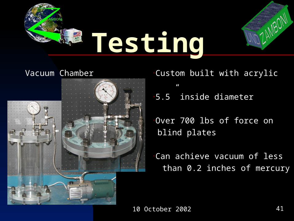
10 October 2002 41
TestingVacuum Chamber •Custom built with acrylic
•5.5” inside diameter
•Over 700 lbs of force on blind plates
•Can achieve vacuum of less than 0.2 inches of mercury

10 October 2002 42
AIAAAmerican Institute of Aeronautics and Astronautics
•Unites UND Aerospace, Space Studies, and Engineering students
•Access to UND Student Organization funding
•Tentative UND AIAA Student Branch, January 2003

10 October 2002 43
ChrisSchmidt

10 October 2002 44
USSS•2002 University Space Systems Symposium
•November 8-10, 2002
•University of Hawaii-Manoa
Attendees: Jon Fargo Jon Lovseth Chris Schmidt Jason Senti Chang-Hee Won

10 October 2002 45
CubeSat Benefits
•Low cost
•Workforce training
•Recruitment
•New space technology
•Educational outreach
•Challenging, motivational, educational
10 October 2002 46
Special Thanks
•Dr. John Ettling, V.P. of Academic Affairs and Provost
•Prof. Arnie Johnson, Chair of Electrical Engineering
•Dr. Donald Moen, P.E., Chair of Mechanical Engineering
•Dr. John Watson, Dean School of Engineering and Mines
•Dr. Shanaka de Silva, North Dakota Space Grant
•Intercollegiate Academics Fund (VPAA’s Office)


![Cartografias bicha [ ZAMBONI ].pdf](https://img.pdfslide.net/doc/110x75/577cd9a71a28ab9e78a3dab6/cartografias-bicha-zamboni-pdf.jpg)