Embed Size (px)
Citation preview

M e c h a n i c a l a n a l y s i s Wh
it
eP
aP
er
w w w . m e n t o r . c o m
10 Tips for predicTing coMponenT TeMperaTures… a high-level ‘how To’ guide

10 Tips for predicting component Temperatures… a high-level ‘how To’ guide
w w w. m ento r.co m2 [9]
Component temperature prediCtion
why is coMponenT TeMperaTure predicTion iMporTanT?
Component temperature prediction is important from a number of points of view. Historically component temperature has been correlated with reliability, with early studies relating field failure rates to component temperature. More recently physics-based reliability prediction has related failure rates of electronic assemblies to the magnitude of temperature change over an operational cycle (power-on, power-off, power-on…), and rate of temperature change, both of which are influenced by steady-state operating temperature. Failures are often attributed to solder joint fatigue. In some applications, like computing, CPU speed is adversely affected by temperature, and in other cases components have to run at very similar temperatures to avoid timing issues. High temperatures can cause operational issues, such as latchup. Whether the intention is to increase reliability, improve performance, or avoid problems during operation, accurate prediction of component temperatures helps thermal designers to achieve their goals.
MaxiMizing cerTainTy in coMponenT TeMperaTure predicTion
Reliable, accurate prediction of component temperatures allows designers to understand how close the design values come to the maximum allowable1 temperature. This white paper discusses how to achieve high fidelity component temperature prediction across the design flow, and to gain increased confidence in the final simulation results.
#1: Model Key coMponenTs expliciTly
It is perhaps self-evident that in order to accurately predict a key component’s temperature the component should be modelled explicitly as part of the thermal simulation. However, not all components need to be modelled, and it is often impractical to do so. Small components with a low power density that are not particularly thermally sensitive can be regarded as thermally benign, and do not need to be represented discretely. Heat from these components can be added as a background heat source applied over the whole board, or as a footprint heat source on the board. FloTHERM and FloTHERM PCB provide filtering options to do this automatically in late design when the populated board is imported from the EDA system.
Larger components may disrupt the air flow, requiring them to be represented directly as 3D objects. One class of component that can fall into this category are electrolytic capacitors, used for example in power supplies, are thermally sensitive, with a low maximum allowable temperature.
Large, high-power components and components with a high power density will need to be modelled discretely, as their thermal management and their influence on neighboring components is important to the overall thermal design of the product.
#2: use good power esTiMaTes
As noted above, part of the decision as to whether it is necessary to represent a component directly depends on its power density, which is the component power divided by its footprint area.
It is worth re-checking decisions about which components to model discretely as the design evolves, and more information becomes available. In early design it may only be possible to use the maximum rated power for the component in place of an estimate of the likely power consumption. Power budgets for individual components, and for the board as a whole, change over the course of the design, so these need to be re-checked on a regular basis.
Power estimates for components can be obtained using for example Mentor Graphics Modelsim to create a RTL based power estimate.
1 Which could be a junction or case temperature, specified in the component’s datasheet.

10 Tips for predicting component Temperatures… a high-level ‘how To’ guide
w w w. m ento r.co m3 [9]
#3: use The righT pacKage TherMal Model
Component thermal models were introduced in our whitepaper “10 Tips for Streamlining PCB Thermal Design” [1]. The choice of component thermal model depends on several factors.
In early design before the board is routed, or the number of layers in the board is known, accurate component temperature prediction is simply not possible, so a thermally-sophisticated model of the component is not called for. Later in the design when the model of the PCB can be refined the component thermal model should also be refined.
Choices about the most appropriate component thermal model are iterative, as components that are predicted to be hot2 self-indicate the need to both refine the component’s thermal model and to perhaps consider a component-specific thermal management solution.
#4: use coMpacT TherMal Models froM early design
In [1] we talked about the need to model components accurately and use a 3D representation of the component in the thermal design before package selection, and we introduced 2-Resistor and DELPHI compact thermal models. Here we discuss in more detail the predictive accuracy of these models.
2-resisTor Models
As noted, a 2-Resistor compact thermal model (CTM) is the lowest fidelity model that is capable of predicting both case and junction temperatures. One benefit is that it does not require any more mesh than a simple conducting block, so using 2-Resistor models has no negative impact on simulation time. Although this has the lowest computational burden, the worst case error in junction temperature prediction can be as high as ±30% and varies with both package type and package size.
The junction-to-case resistance and junction-to-board resistance thermal metrics this model is based on are measured under standardized conditions. The JEDEC Standard JESD15-3 requires the junction-to-board resistance to be measured on a 2s2p board with continuous power and ground planes. The junction-to-case resistance is measured by pressing the top of the package against a cold plate. As a result, the predictive accuracy of the 2-Resitor model is higher the more closely the application resembles the test conditions. For the junction-to-case resistance, the application environment that most closely corresponds to the test environment is when the component has a heatsink that covers the whole of the package surface. For this reason 2-Resistor models can be used to initially assess the size of heatsink required.
Note that the top surface of a 2-Resistor model is an isothermal node representing the case, so that the base of the heatsink will be isothermal. A 2-Resistor model can therefore be used to determine the number of fins, fin thickness, and fin height needed to reduce the air-side thermal resistance of the heatsink, but not the base thickness needed to adequately spread the heat to ensure that heat passing to the outer fins is not overly restricted.
rc-ladder Models
For packages that have a single heat flow path, such as LEDs and TO-style packages, there is a JEDEC standard approach [2] for measuring a thermal resistor-capacitor model of the heat flow path from the junction down to the package tab. Note that this method does not directly provide a thermal resistance to the exposed top surface of the package. However, provided this can be estimated by some means, Mentor Graphics’ transient thermal tester T3Ster can be used to create an RC-ladder thermal model that takes this into account.
2 In early design ‘hot’ will be in the context of quite a wide design safety margin.
10 Tips for predicting component Temperatures… a high-level ‘how To’ guide
w w w. m ento r.co m4 [9]
T3Ster is the industry-leading solution for measuring packaged ICs to create these thermal models, which can be used directly as a Network Assembly in FloTHERM. Unlike 2-Resistor models which only contain thermal resistors, these models include thermal capacitors, and so can be used for transient simulations. These models can give excellent results when the application environment is close to that of the test cold plate environment, e.g. when the package is soldered to a MCPCB or a copper pad on a high conductivity board.
delphi Models
DELPHI models are so-named as they originated from the DELPHI Project coordinated by Flomerics in the late 1990s. These models have partitioned top and bottom surfaces, with a matrix of thermal resistors to connect these surfaces to the junction and/or to one another. These additional internal thermal resistors allow the heat flow paths within the package to adjust depending on the boundary conditions, and in many applications the model will predict the junction temperature to accuracy well within ±10%, being a worst-case figure. In general DELPHI models are adequate for detailed thermal design work of all but the most thermally-critical packages, stacked or 3D ICs, or where additional information is needed from the simulation, e.g. the temperature distribution on the die surface.
deTailed Models
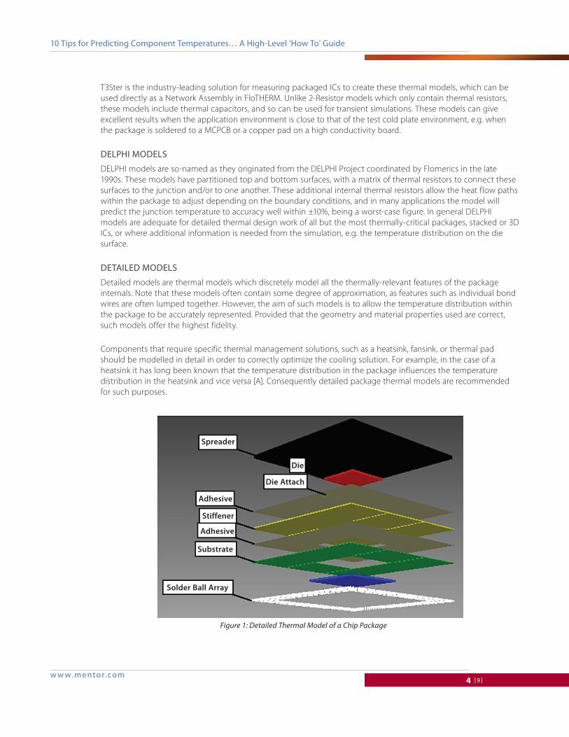
Detailed models are thermal models which discretely model all the thermally-relevant features of the package internals. Note that these models often contain some degree of approximation, as features such as individual bond wires are often lumped together. However, the aim of such models is to allow the temperature distribution within the package to be accurately represented. Provided that the geometry and material properties used are correct, such models offer the highest fidelity.
Components that require specific thermal management solutions, such as a heatsink, fansink, or thermal pad should be modelled in detail in order to correctly optimize the cooling solution. For example, in the case of a heatsink it has long been known that the temperature distribution in the package influences the temperature distribution in the heatsink and vice versa [A]. Consequently detailed package thermal models are recommended for such purposes.
Spreader
Adhesive
Stiffener
Substrate
Solder Ball Array
Die
Die Attach
Adhesive
Figure 1: Detailed Thermal Model of a Chip Package
10 Tips for predicting component Temperatures… a high-level ‘how To’ guide
w w w. m ento r.co m5 [9]
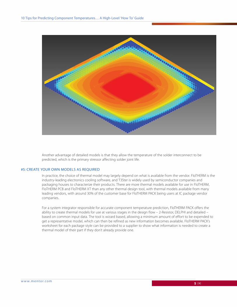
Another advantage of detailed models is that they allow the temperature of the solder interconnect to be predicted, which is the primary stressor affecting solder joint life.
#5: creaTe your own Models as required
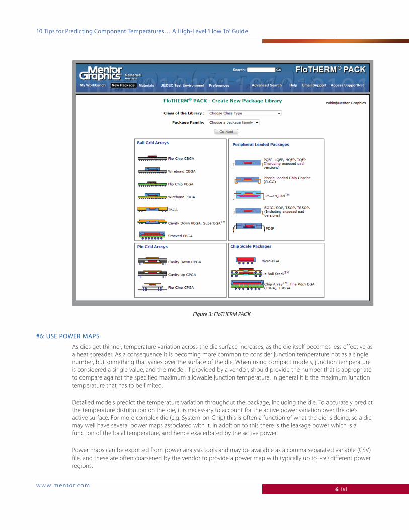
In practice, the choice of thermal model may largely depend on what is available from the vendor. FloTHERM is the industry-leading electronics cooling software, and T3Ster is widely used by semiconductor companies and packaging houses to characterize their products. There are more thermal models available for use in FloTHERM, FloTHERM PCB and FloTHERM XT than any other thermal design tool, with thermal models available from many leading vendors, with around 30% of the customer base for FloTHERM PACK being users at IC package vendor companies.
For a system integrator responsible for accurate component temperature prediction, FloTHERM PACK offers the ability to create thermal models for use at various stages in the design flow – 2-Resistor, DELPHI and detailed – based on common input data. The tool is wizard based, allowing a minimum amount of effort to be expended to get a representative model, which can then be refined as new information becomes available. FloTHERM PACK’s worksheet for each package style can be provided to a supplier to show what information is needed to create a thermal model of their part if they don’t already provide one.
10 Tips for predicting component Temperatures… a high-level ‘how To’ guide
w w w. m ento r.co m6 [9]
#6: use power Maps
As dies get thinner, temperature variation across the die surface increases, as the die itself becomes less effective as a heat spreader. As a consequence it is becoming more common to consider junction temperature not as a single number, but something that varies over the surface of the die. When using compact models, junction temperature is considered a single value, and the model, if provided by a vendor, should provide the number that is appropriate to compare against the specified maximum allowable junction temperature. In general it is the maximum junction temperature that has to be limited.
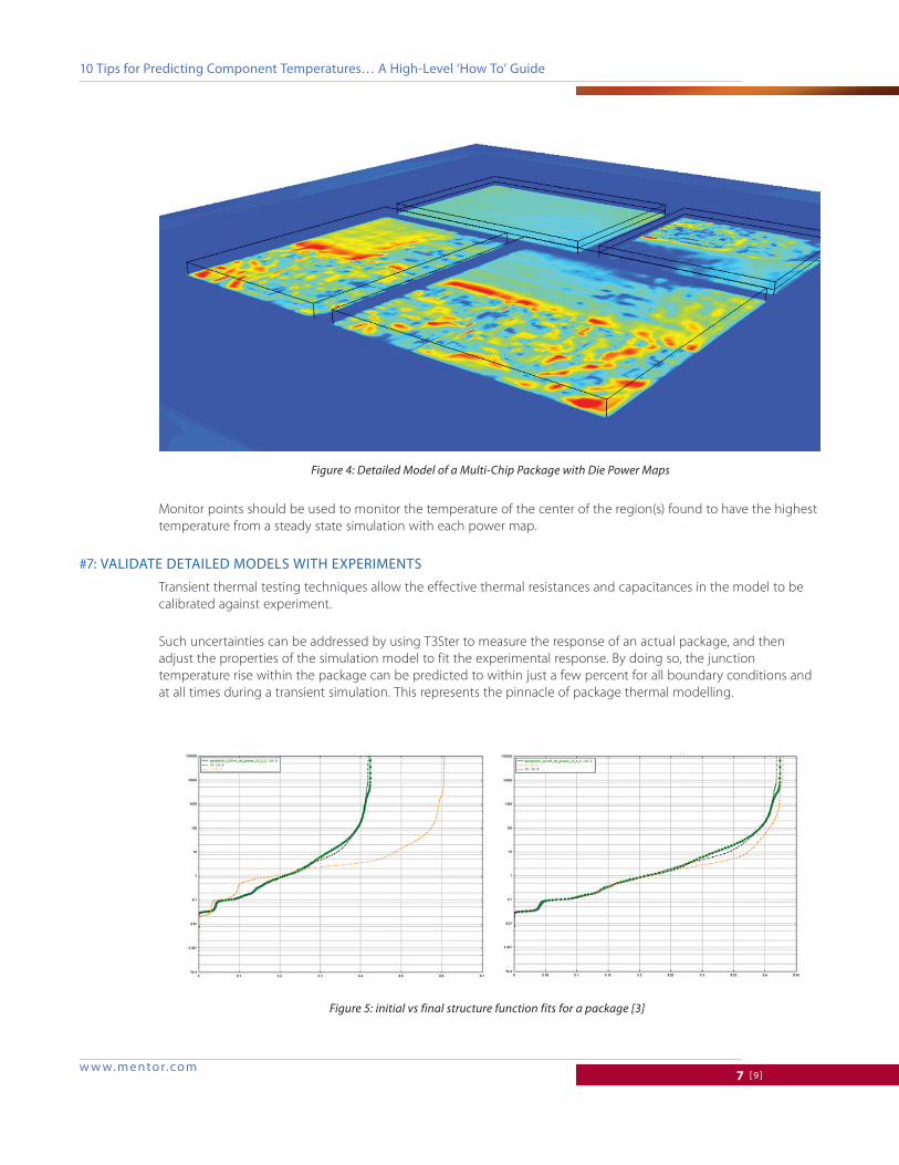
Detailed models predict the temperature variation throughout the package, including the die. To accurately predict the temperature distribution on the die, it is necessary to account for the active power variation over the die’s active surface. For more complex die (e.g. System-on-Chip) this is often a function of what the die is doing, so a die may well have several power maps associated with it. In addition to this there is the leakage power which is a function of the local temperature, and hence exacerbated by the active power.
Power maps can be exported from power analysis tools and may be available as a comma separated variable (CSV) file, and these are often coarsened by the vendor to provide a power map with typically up to ~50 different power regions.
Figure 3: FloTHERM PACK
10 Tips for predicting component Temperatures… a high-level ‘how To’ guide
w w w. m ento r.co m7 [9]
Monitor points should be used to monitor the temperature of the center of the region(s) found to have the highest temperature from a steady state simulation with each power map.
#7: validaTe deTailed Models wiTh experiMenTs
Transient thermal testing techniques allow the effective thermal resistances and capacitances in the model to be calibrated against experiment.
Such uncertainties can be addressed by using T3Ster to measure the response of an actual package, and then adjust the properties of the simulation model to fit the experimental response. By doing so, the junction temperature rise within the package can be predicted to within just a few percent for all boundary conditions and at all times during a transient simulation. This represents the pinnacle of package thermal modelling.
Figure 4: Detailed Model of a Multi-Chip Package with Die Power Maps
Figure 5: initial vs final structure function fits for a package [3]

10 Tips for predicting component Temperatures… a high-level ‘how To’ guide
w w w. m ento r.co m8 [9]
For package designers, a validated detailed thermal model is a prerequisite for subsequent improvements in design, materials and processing, and is essential for finite-element based stress prediction by ensuring the correct temperature distribution within the package and hence its warpage and structural interaction with the PCB.
From an end user’s perspective, a validated detailed thermal model is the best starting point for any custom heatsink design.
#8: design cusToM heaTsinK soluTions
Up to this point a standard design of heatsink will have been selected to ensure that the component can be adequately cooled, however this may be a sub-optimal solution.
The purpose of custom heatsink design optimization is to maximize the heat transfer for the minimum system pressure drop and wake region formed behind the heatsink. The contact area between the heatsink and the package body can also be optimized to prevent heat spreading in the base of the heatsink and then flowing back into the package body around its periphery.
Note that because the major heat flow path out of the package will be into the heatsink, designing a custom heatsink can start before the board is routed.
#9: accuraTely capTure TherMal inTerface MaTerial resisTance
Thermal Interface Material (TIM) thermal conductivity can be accurately measured as a function of temperature with T3Ster DynTIM [4], allowing the most suitable TIM material to be chosen for a particular application e.g. between a component and a heatsink. Depending on the material chosen, how well this wets the surfaces depends on many things, such that the total thermal resistance including the interfacial resistances on each side of the TIM. It is worth noting that the thermal resistance of the TIM can be a substantial contribution to the junction temperature rise, and so accurate data for the overall TIM thermal resistance is important for accurate component temperature prediction.
#10: provide accuraTe TeMperaTures for Mechanical sTress predicTion
As IC packaging challenges continue to increase, package vendors are finding the need to design for thermally-induced stresses that more closely match those the part will experience in the application environment.
From Version 10 of FloTHERM, assembly temperatures can be exported for use in a finite-element stress tool to provide the thermal strain as a boundary condition for the stress calculation. Temperatures are intelligently mapped onto the finite element mesh accounting for differences in the shapes of the geometric objects that might exist between the two analysis disciplines. The assembly under consideration can for example include the package, heatsink if attached, and a section of the board onto which the part is soldered.
ConCluding remarks
This white paper provides an overview of the key considerations in Component Temperature Prediction. It is by no means exhaustive, with many details not covered. If you are responsible for ensuring component temperatures do not exceed specified limits and want to know how Mentor Graphics’ thermal design software can help, and what is the right product for your application, then please contact us through the Mentor Graphics Mechanical Analysis web page www.mentor.com/products/mechanical

10 Tips for predicting component Temperatures… a high-level ‘how To’ guide
©2014 Mentor graphics corporation, all rights reserved. This document contains information that is proprietary to Mentor graphics corporation and may be duplicated in whole or in part by the original recipient for internal business purposes only, provided that this entire notice appears in all copies. in accepting this document, the recipient agrees to make every reasonable effort to prevent unauthorized use of this information. all trademarks mentioned in this document are the trademarks of their respective owners.
F o r t h e l a t e s t p r o d u c t i n f o r m a t i o n , c a l l u s o r v i s i t : w w w . m e n t o r . c o m
Mgc 01-14 Tech11760
aCknowledgements
Dr John Parry, CEng, CITP, MBCS, MIEEE Dr Robin Bornoff
referenCes
1. Rosten, H.I. & Viswanath, R. (1994) Thermal modelling of the Pentium processor package, Proceedings of 44th Electronic Components and Technology Conference, 1994, pp. 421 - 428
2. JEDEC JESD51-14 “Transient Dual Interface Test Method for the Measurement of the Thermal Resistance Junction to Case of Semiconductor Devices with Heat Flow through a Single Path,” November 2010 http://www.jedec.org/standards-documents/results/jesd51-14
3. Bornoff, Robin & Vass-Varnai, Andras (2013) A Detailed IC Package Numerical Model Calibration Methodology, Proceedings of SEMI-THERM 29, San Jose, March 2013
4. http://www.mentor.com/products/mechanical/products/dyntim