Embed Size (px)
Citation preview
7/25/2019 10 Transformer Noise
http://slidepdf.com/reader/full/10-transformer-noise 1/6113
Understanding Transformer Noise
ISO 9001:2008REGISTERED
7/25/2019 10 Transformer Noise
http://slidepdf.com/reader/full/10-transformer-noise 2/6
114
T r a n s f o r m e r N o i s e
UNDERSTANDINGTRANSFORMERNOISE Noise is dened as unwanted sound. But,what is unwanted sound? A mellow soundto some, can be completely unacceptableto others. Attending rock concerts with
noise levels at eardrum rattling levels istotally stimulating to many people. Putthose same people in a different environ-ment, possibly next to a transformer, andthere will be wild protestations. Thedifference then between noise and soundis in the “ear of the hearer”. Since it isnecessary to place electrical apparatusalongside a wide spectrum of people wehave to accept the inevitable, that evenunder normal conditions, somebody willalways complain.
Transformer “humming” has been knownto soothe people (which makes it a sound)but generally it is reckoned to be a nui-sance (which makes it a noise).
The causes and reduction of transformernoise has been the subject of many learnedpapers for at least two generations. Ithas come to prominence again, mainlybecause transformers are placed closer tothe populace—in high rise ofce build-
ings, apartments, shopping malls and intheir gardens. It is becoming even morenecessary to locate these units carefullyand some planning, preferably ahead oftime, is needed.
The remedies we use to counter possibleobjections to transformer noises are variedand in some cases, expensive, because we
cannot produce a blanket remedy to coverall situations. It is absolutely necessary toconsider each case on its merits, to applythe general rules of acoustic technologyand to be familiar with the causes oftransformer noise. The techniques canbe explained simply enough for anyone tounderstand and the rules are, in the maineasy to apply.
The BEST RULE however is to PLANAHEAD. Finding out you have a noiseproblem (or vibration problem) after theplacement of the unit is costly, time con-suming and frustrating.
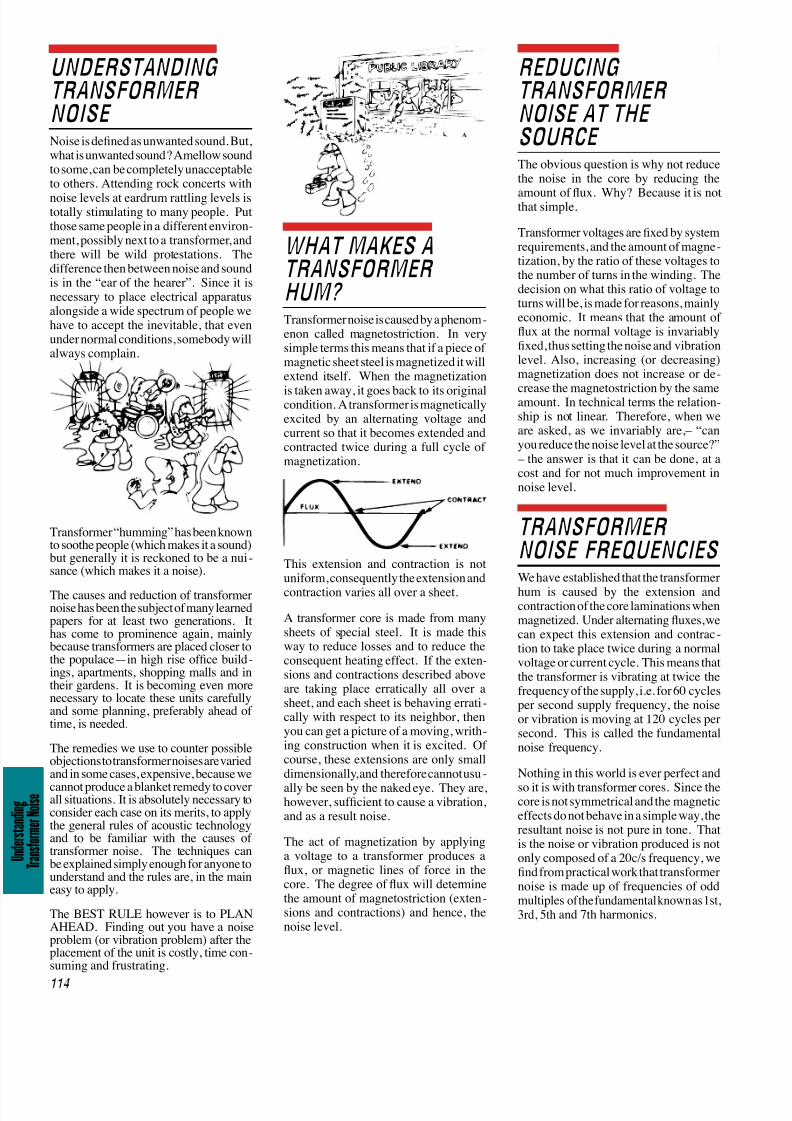
WHAT MAKES ATRANSFORMERHUM? Transformer noise is caused by a phenom-
enon called magnetostriction. In verysimple terms this means that if a piece ofmagnetic sheet steel is magnetized it willextend itself. When the magnetization
is taken away, it goes back to its originalcondition. A transformer is magneticallyexcited by an alternating voltage andcurrent so that it becomes extended andcontracted twice during a full cycle ofmagnetization.
This extension and contraction is notuniform, consequently the extension and
contraction varies all over a sheet.
A transformer core is made from manysheets of special steel. It is made thisway to reduce losses and to reduce theconsequent heating effect. If the exten-sions and contractions described aboveare taking place erratically all over asheet, and each sheet is behaving errati-cally with respect to its neighbor, thenyou can get a picture of a moving, writh-
ing construction when it is excited. Ofcourse, these extensions are only smalldimensionally, and therefore cannot usu-
ally be seen by the naked eye. They are,however, sufcient to cause a vibration,and as a result noise.
The act of magnetization by applyinga voltage to a transformer produces aux, or magnetic lines of force in thecore. The degree of ux will determinethe amount of magnetostriction (exten-sions and contractions) and hence, thenoise level.
REDUCINGTRANSFORMERNOISE AT THESOURCE The obvious question is why not reducethe noise in the core by reducing the
amount of ux. Why? Because it is notthat simple.
Transformer voltages are xed by systemrequirements, and the amount of magne-tization, by the ratio of these voltages tothe number of turns in the winding. Thedecision on what this ratio of voltage toturns will be, is made for reasons, mainlyeconomic. It means that the amount ofux at the normal voltage is invariablyxed, thus setting the noise and vibrationlevel. Also, increasing (or decreasing)magnetization does not increase or de-
crease the magnetostriction by the sameamount. In technical terms the relation-ship is not linear. Therefore, when weare asked, as we invariably are,– “canyou reduce the noise level at the source?” – the answer is that it can be done, at acost and for not much improvement innoise level.
TRANSFORMERNOISE FREQUENCIES We have established that the transformer
hum is caused by the extension andcontraction of the core laminations whenmagnetized. Under alternating uxes, wecan expect this extension and contrac-tion to take place twice during a normalvoltage or current cycle. This means thatthe transformer is vibrating at twice thefrequency of the supply, i.e. for 60 cyclesper second supply frequency, the noiseor vibration is moving at 120 cycles persecond. This is called the fundamentalnoise frequency.
Nothing in this world is ever perfect and
so it is with transformer cores. Since thecore is not symmetrical and the magneticeffects do not behave in a simple way, theresultant noise is not pure in tone. Thatis the noise or vibration produced is notonly composed of a 20c/s frequency, wend from practical work that transformernoise is made up of frequencies of oddmultiples of the fundamental known as 1st,
3rd, 5th and 7th harmonics.
7/25/2019 10 Transformer Noise
http://slidepdf.com/reader/full/10-transformer-noise 3/6
115
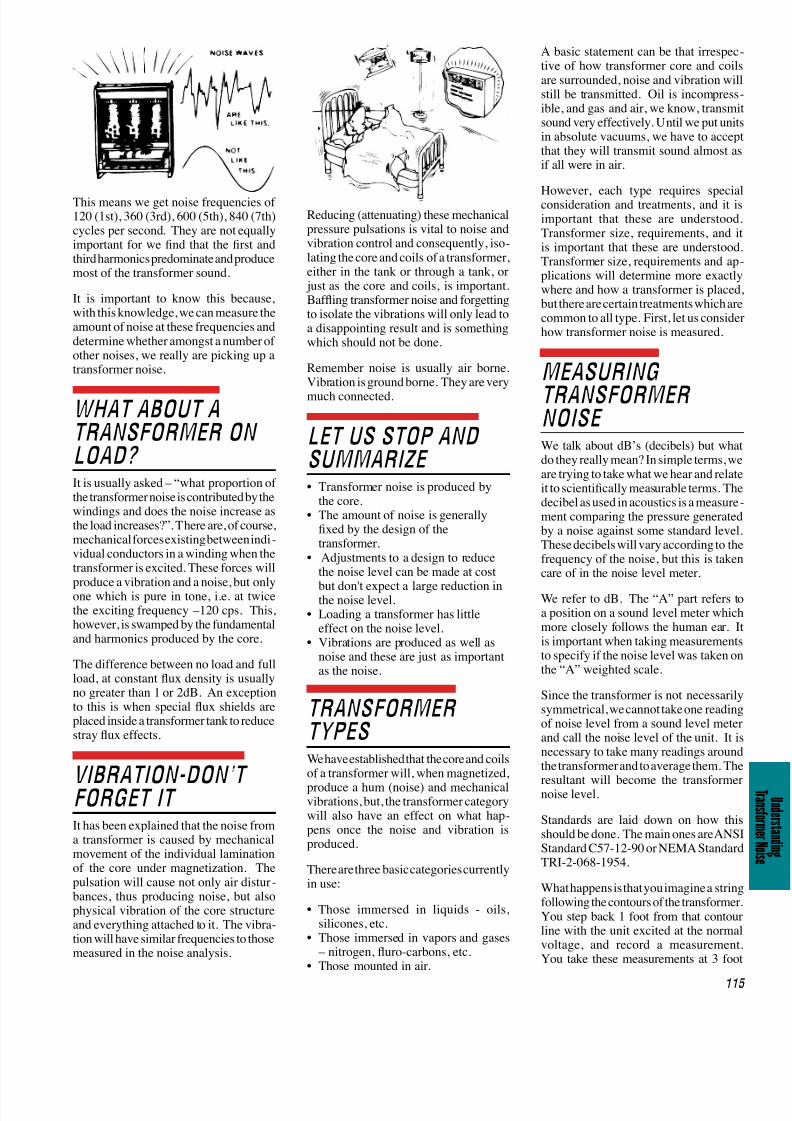
This means we get noise frequencies of120 (1st), 360 (3rd), 600 (5th), 840 (7th)cycles per second. They are not equallyimportant for we nd that the rst andthird harmonics predominate and producemost of the transformer sound.
It is important to know this because,with this knowledge, we can measure theamount of noise at these frequencies anddetermine whether amongst a number ofother noises, we really are picking up atransformer noise.
WHAT ABOUT ATRANSFORMER ONLOAD? It is usually asked – “what proportion ofthe transformer noise is contributed by thewindings and does the noise increase asthe load increases?”. There are, of course,mechanical forces existing between indi-vidual conductors in a winding when thetransformer is excited. These forces willproduce a vibration and a noise, but onlyone which is pure in tone, i.e. at twicethe exciting frequency –120 cps. This,however, is swamped by the fundamentaland harmonics produced by the core.
The difference between no load and fullload, at constant ux density is usuallyno greater than 1 or 2dB. An exceptionto this is when special ux shields areplaced inside a transformer tank to reducestray ux effects.
VIBRATION-DON’TFORGET IT It has been explained that the noise froma transformer is caused by mechanicalmovement of the individual laminationof the core under magnetization. Thepulsation will cause not only air distur-bances, thus producing noise, but alsophysical vibration of the core structureand everything attached to it. The vibra-tion will have similar frequencies to thosemeasured in the noise analysis.
Reducing (attenuating) these mechanicalpressure pulsations is vital to noise andvibration control and consequently, iso-lating the core and coils of a transformer,either in the tank or through a tank, or just as the core and coils, is important.Bafing transformer noise and forgettingto isolate the vibrations will only lead toa disappointing result and is somethingwhich should not be done.
Remember noise is usually air borne.Vibration is ground borne. They are very
much connected.
LET US STOP ANDSUMMARIZE • Transformer noise is produced by
the core.• The amount of noise is generally
xed by the design of thetransformer.
• Adjustments to a design to reducethe noise level can be made at cost
but don't expect a large reduction inthe noise level.
• Loading a transformer has littleeffect on the noise level.
• Vibrations are produced as well asnoise and these are just as importantas the noise.
TRANSFORMERTYPES We have established that the core and coilsof a transformer will, when magnetized,
produce a hum (noise) and mechanicalvibrations, but, the transformer categorywill also have an effect on what hap-
pens once the noise and vibration isproduced.
There are three basic categories currentlyin use:
• Those immersed in liquids - oils,silicones, etc.
• Those immersed in vapors and gases – nitrogen, uro-carbons, etc.
• Those mounted in air.
A basic statement can be that irrespective of how transformer core and coilsare surrounded, noise and vibration wilstill be transmitted. Oil is incompressible, and gas and air, we know, transmisound very effectively. Until we put unitin absolute vacuums, we have to accepthat they will transmit sound almost asif all were in air.
However, each type requires speciaconsideration and treatments, and it isimportant that these are understoodTransformer size, requirements, and iis important that these are understoodTransformer size, requirements and applications will determine more exactlywhere and how a transformer is placedbut there are certain treatments which arecommon to all type. First, let us considehow transformer noise is measured.
MEASURING
TRANSFORMERNOISE We talk about dB’s (decibels) but whatdo they really mean? In simple terms, weare trying to take what we hear and relateit to scientically measurable terms. Thedecibel as used in acoustics is a measurement comparing the pressure generatedby a noise against some standard levelThese decibels will vary according to thefrequency of the noise, but this is takencare of in the noise level meter.
We refer to dB. The “A” part refers toa position on a sound level meter whichmore closely follows the human ear. Iis important when taking measurementsto specify if the noise level was taken onthe “A” weighted scale.
Since the transformer is not necessarilysymmetrical, we cannot take one readingof noise level from a sound level meterand call the noise level of the unit. It inecessary to take many readings aroundthe transformer and to average them. The
resultant will become the transformernoise level.
Standards are laid down on how thisshould be done. The main ones are ANSIStandard C57-12-90 or NEMA StandardTRI-2-068-1954.
What happens is that you imagine a stringfollowing the contours of the transformerYou step back 1 foot from that contourline with the unit excited at the normavoltage, and record a measurementYou take these measurements at 3 foot
7/25/2019 10 Transformer Noise
http://slidepdf.com/reader/full/10-transformer-noise 4/6
116
T r a n s f o r m e r N o i s e
intervals along the imaginary string.The measurements are totaled and thenaveraged. The result is the transformernoise level.
To measure amounts of noise in eachfrequency range you need a frequencyanalyzer. This is a worthwhile acquisi-tion.
It is always necessary to measure thebackground (ambient) noise level before
you start and when you nish the tests.There has to be a difference betweenthe ambient reading and the averagenoise level of 7dB or better, for it to bevalid, otherwise you could be increasingthe actual reading of the transformer.This sometimes makes night owls ofthe testers!
SO NOW WE KNOW WHERE THENOISE COMES FROM AND HOWTO MEASURE IT. WHAT CAN WEDO ABOUT IT?
First of all, accept that there is a noiseand you are stuck with it. We haveto consider how to avoid making it a
nuisance to people. The most obviousstrategy is to place the transformer in aeld miles away from habitation. Thenoise level drops away as the square ofthe distance from the noise, but even so,it would take a very large eld to hideit. However, we invariably have to placetransformers near people and we mustface up to that fact.
We have both noise and vibration toworry about and as we have said NOISEis usually air borne, VIBRATION isstructure borne.
METHODS OFCUTTING AIR BORNENOISE • Put the object in room in which thewalls, oor are massive enough to re-duce the noise to a person listening onthe other side. Noise is usually reduced
(attenuated) as it tries to pass througha massive wall. Walls can be of brick,steel, concrete, lead, etc.
• Put the object inside an enclosure whichuses a limp wall technique. This is a meth-od which uses two thin plates separatedby viscous (rubbery) material. The noisehits the inner sheet – its energy (some) isused up inside the viscous material. Theouter sheet should not vibrate.
• Build a screen wall around the unit.This is cheaper than a full room. It willreduce the noise to those near the wall,but the noise will get over the screen andfall elsewhere (at a lower level). Screenshave been made from wood, concrete,
brick and with dense bushes (althoughthe latter becomes psychological).
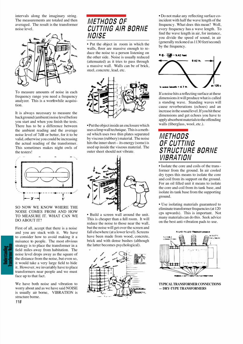
• Do not make any reecting surface co-incident with half the wave length of thefrequency. What does this mean? Well,every frequency has a wave length. Tond the wave length in air, for instance,you divide the speed of sound, in air(generally reckoned as 1130 feet/second)by the frequency.
If a noise hits a reecting surface at thesedimensions it will produce what is calleda standing wave. Standing waves willcause reverberations (echoes) and anincrease in the sound level. If you hit thesedimensions and get echoes you have to
apply absorbent materials to the offendingwalls (berglass, wool, etc.).
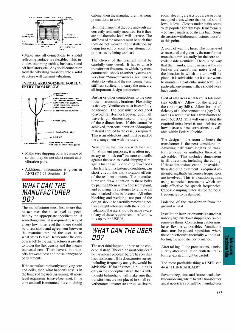
METHODSOF CUTTINGSTRUCTURE BORNEVIBRATION • Isolate the core and coils of the trans-former from the ground. In air cooleddry types this means to isolate the core
and coil from its support on the ground.For an oil lled unit it means to isolatethe core and coil from its tank base, andisolate its tank base from the supportingground.
• Use isolating materials guaranteed toeliminate transformer frequencies (at 120cps upwards). This is important. Notmany materials can do this. Seek adviceon the best anti-vibration pads to use.
TYPICAL TRANSFORMER CONNECTIONS
— DRY-TYPE TRANSFORMERS
7/25/2019 10 Transformer Noise
http://slidepdf.com/reader/full/10-transformer-noise 5/6
117
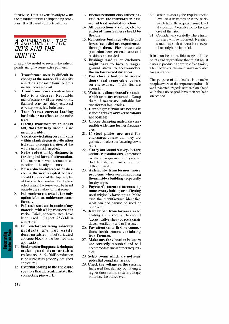
• Make sure all connections to a solid
reecting surface are exible. This in-cludes incoming cables, busbars, standoff insulators, etc. Any solid connectionfrom the vibrating transformer to a solidstructure will transmit vibration.
TYPICAL ARRANGEMENT FOR H. V.
ENTRY FROM BELOW
• Make sure shipping bolts are removedso that they do not short circuit anti-vibration pads.
• Additional information is given in
ANSI C57.94, Section 4.10.
WHAT CAN THEMANUFACTURERDO? The manufacturer must rst insure thathe achieves the noise level as speci-ed by the appropriate specication. Ifsomething unusual is required by way ofa very low noise level then there shouldbe discussions and agreement between
the manufacturer and the user, as towhat steps to take. Remember the onlycourse left to the manufacturer is usuallyto lower the ux density and this meansincreased cost. There have to be trade-offs between cost and noise annoyanceor treatments.
If the manufacturer is only supplying coreand coils, then what happens next is inthe hands of the user, assuming all noiselevel requirements have been met. If thecore and coil is mounted in a containing
cabinet then the manufacturer has someprecautions to take.
He must insure that the core and coils arecorrectly resiliently mounted, for it theyare not, the noise level will increase. Thestiffness of the mounts must be such thatthey do not weaken the installation bybeing too soft or spoil their attenuationproperties by being too hard.
The choice of the resilient must becarefully considered. It has to absorbtransformer frequencies which, by mostcommercial shock absorber systems arevery low. “Shore” hardness (resilience),ability to withstand the environment andstiffness sufcient to carry the unit, areall important design parameters.
Busbar or other connections to the coremust not transmit vibrations. Flexibilityis the key. Ventilators must be carefullypositioned. The core must be designedto avoid transformer frequencies of halfwave-length dimensions, or multiplesof these dimensions. If this cannot beachieved, then consideration of dampingmaterial applied to the case, is required.This is an added cost and must be part ofthe arrangement with the user.
Now comes the interface with the user.For shipment purposes, it is often nec-essary to “block out” the core and coilsagainst the case, to avoid shipping dam-
age. This can include holding down boltswhich if left in a fastened condition, canshort circuit the anti-vibration effects
of the resilient mounts. The manufac-turer can draw attention to these boltsby painting them with a orescent paint,and advising his customer to remove allsuch marked bolts before use. All otherblocking and wedging, not part of thedesign, should be carefully removed sincethese might interfere with the vibrationisolation. The user should be made awareof any of these requirements. After this,it is up to the USER!
WHAT CAN THE USERDO? The user thinking should start at the con-ceptual stage. If he can, he must consider ifhe has a noise problem before he specieshis transformer. If he does, a noise surveyincluding frequency analysis, would beadvisable. If for instance, a building isonly in the conceptual stage, then a littlethought beforehand will make sure thattransformers are not placed in small re-verberant rooms next to a proposed board
room, sleeping areas, study areas or otheroccupied areas where the normal soundlevel is low. Closets under stairs seemvery popular for dry type transformers – but are usually acoustically bad. Somediscussion with the manufacturer is usefuat this point.
A word of warning here. The noise leveas measured and given by the transformer
manufacturer is usually for the core andcoils inside a cubicle. There is no waythat the manufacturer can assess the ef fect on the transformer noise level bythe location in which the unit will beplace. It is advisable that if a user wantto maintain a particular noise level in aparticular environment they should workbackwards.
First of all assess what level is tolerable(say 65dBA). Allow for the effect othe room (say 3dB). Allow for the efciency of all the connections (say 2dB)and as a result ask for a transformer tomeet 60dBA! This will ensure that therequired noise level is met. Advice onhow to assess these corrections is available within Federal Pacic.
The design of the room to house thetransformer is the next considerationAvoiding half wave-lengths of transformer noise, or multiples thereof, isadvisable. This includes dimensionsin all directions, including the ceilingIf these dimensions cannot be avoidedthen damping treatment is required remembering that transformer frequencieare involved. This is a caution againsusing acoustical treatments which areonly effective for speech frequenciesChoose damping materials for the noisefrequencies to be damped.
Isolation of the transformer from theground is vital.
Installation instructions must ensure thanobody tightens down shipping bolts – buremoves them. Connecting cables musbe as exible as possible. Ventilationducts must be placed in positions where
these are effective thermally without af fecting the acoustic performance.
After taking all the precautions, a noisesurvey after installation, with the transformer excited might be useful.
The most protable thing a USER cando is ‘THINK AHEAD!”
Save money, time and future headachesby considering where to put a transformerand if necessary consult the manufacturer
7/25/2019 10 Transformer Noise
http://slidepdf.com/reader/full/10-transformer-noise 6/6
118
T r a n s f o r m e r N o i s e
for advice. Do that even if is only to warnthe manufacturer of an impending prob-lem. It will avoid conicts later on.
A SUMMARY - THEDO’S AND THE
DON’TS It might be useful to review the salientpoints and give some extra pointers:
1. Transformer noise is difcult tochange at the source. Flux densityreduction is the main thrust, but thismeans increased cost.
2. Transformer core constructionshelp to a degree. Reputablemanufacturers will use good joints,at steel, consistent thickness, goodcore supports, few bolts, etc.
3
Transformer current loadinghas little or no effect on the noiselevel.
4. Placing transformers in liquid(oil) does not help since oils areincompressible.
5. Vibration – isolating core and coilswithin a tank does assist vibrationisolation although isolation of thewhole tank is still needed.
6. Noise reduction by distance isthe simplest form of attenuation.If it can be achieved without cost–excellent. Usually it cannot.
7. Noise reduction by screens, bushes,etc., is the next simplest but useshould be made of the topographyof the site. Remember the shadoweffect means the noise could be heardoutside the shadow of that screen.
8. Full enclosure is usually the onlyoption left to a troublesome trans-
former.
9. Full enclosure can be made of anymaterial with a high mass/weightratio. Brick, concrete, steel havebeen used. Expect 25-30dBAreductions.
10. Full enclosures using masonryproduct s are not eas i l ydemountable. Prefabricatedconcrete block is the best for thisapplication.
11. Steel, mass or limp panel techniquesmake good demount abl eenclosures. A 15 – 20dBA reductionis possible with properly designedenclosures.
12. External cooling to the enclosurerequires exible treatments to theconnecting pipework.
13. Enclosure mounts should be sepa-
rate from the transformer base – or at least, isolated somehow.
14. All connections - cables, etc. toenclosed transformers should beexible.
15. Remember bushings vibrate andlosses (acoustic) are experiencedthrough them. Flexible acousticprotection between enclosure and
bushings are needed.16. Bushings used in an enclosure
might have to have a longerground sleeve to accommodatethe enclosure roof distances.
17. Pay close attention to accessdoors and removable coverson enclosures. Tight fits areessential.
18. Watch the dimensions of rooms inwhich units are mounted. Dampthem if necessary, suitable fortransformer frequencies.
19. Damping materials are needed if
standing waves or reverberationsare possible.
20. Choose damping materials com-
patible with trans former frequen-
cies.21. If steel plates are used for
enclosures ensure that they aregasketed. Isolate the fastening downbolts.
22. Carry out sound surveys beforeand after installations. Rememberto do a frequency analysis sothat transformer noise can bedifferentiated.
23. Anticipate transformer noiseproblems when accommodatingthem inside a building - especiallyfor dry types.
24. Pay careful attention to removingunnecessary bolting or stiffeningused originally for shipping. Makesure the manufacturer identifieswhat can and cannot be used orremoved.
25. Remember transformers needcooling air in rooms. Be careful(acoustically) when you position airducts, ventilators and grilles, etc.
26. Pay attention to exible connec-tions inside rooms containingtransformers.
27. Make sure the vibration isolatorsare correctly mounted and willaccommodate transformer frequen-cies.
28. Select rooms which are not nearpotential complaint areas.
29. Check the voltage on the system. Increased ux density by having ahigher than normal system voltagewill raise the noise level.
30. When assessing the required noiselevel of a transformer work back-
wards from the required noise levelat a location. Consider the inefcien-cies of the site.
31. Consider very carefully where trans-formers will be mounted. Resilientstructures such as wooden mezza-nines might be harmful.
It has not been possible to give all thepoints and suggestions that might assista user in producing a trouble free (noise)site. However, we are always availablefor assistance.
The purpose of this leaet is to makepeople aware of the important points. Ifwe have encouraged users to plan aheadwith their noise problems then we havesucceeded.