Embed Size (px)
Citation preview

R
10 USB
Integrated Sound System
FBT elettronica SpA - Via Paolo Soprani 1 - Zona Ind.le Squartabue - 62019 RECANATI - ITALY
Tel. 071 750591 - Fax. 071 7505920 - email: [email protected] - www.fbt.it
ENGLISH
INDEX
WARNING - IMPORTANT SAFETY INSTRUCTIONS - PRECAUTIONSGENERAL FEATURESCOVER / HANDLEGENERAL FEATURES DIMENSIONSCONNECTORSARTWORKCONTROLS & FUNCTIONSMono Section / Stereo SectionEffect SectionMaster SectionUSB INTERFACESUPPLY AND POWER SECTIONBLOCK DIAGRAMDIAGRAMSTHE AMICO SYSTEM IN VARIOUS APPLICATIONSTECHNICAL SPECIFICATIONS
AMICO 1O SAT
12/3
45678
9101112131415
16/1718
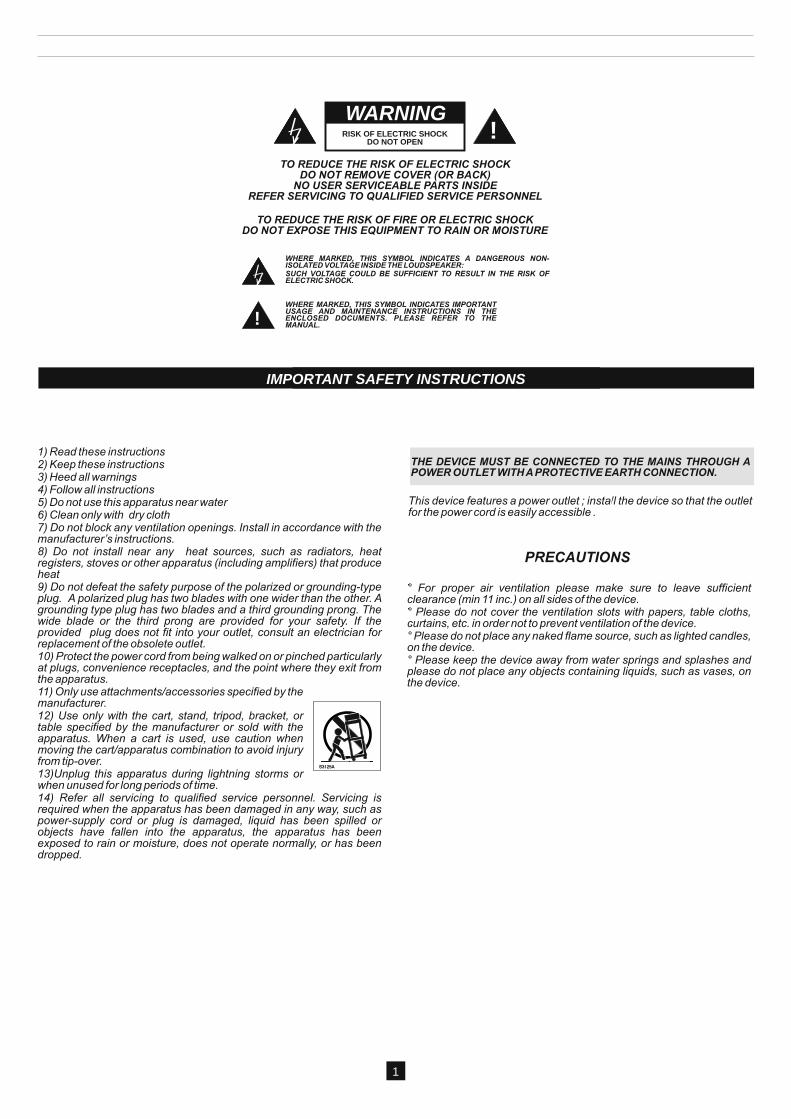
IMPORTANT SAFETY INSTRUCTIONS
TO REDUCE THE RISK OF ELECTRIC SHOCKDO NOT REMOVE COVER (OR BACK)
NO USER SERVICEABLE PARTS INSIDEREFER SERVICING TO QUALIFIED SERVICE PERSONNEL
TO REDUCE THE RISK OF FIRE OR ELECTRIC SHOCKDO NOT EXPOSE THIS EQUIPMENT TO RAIN OR MOISTURE
!WARNING
RISK OF ELECTRIC SHOCKDO NOT OPEN
||
|
<
||
|
<
!
!WARNING
||
|
<
||
|
<
!
IMPORTANT SAFETY INSTRUCTIONS
1
GENERAL FEATURES
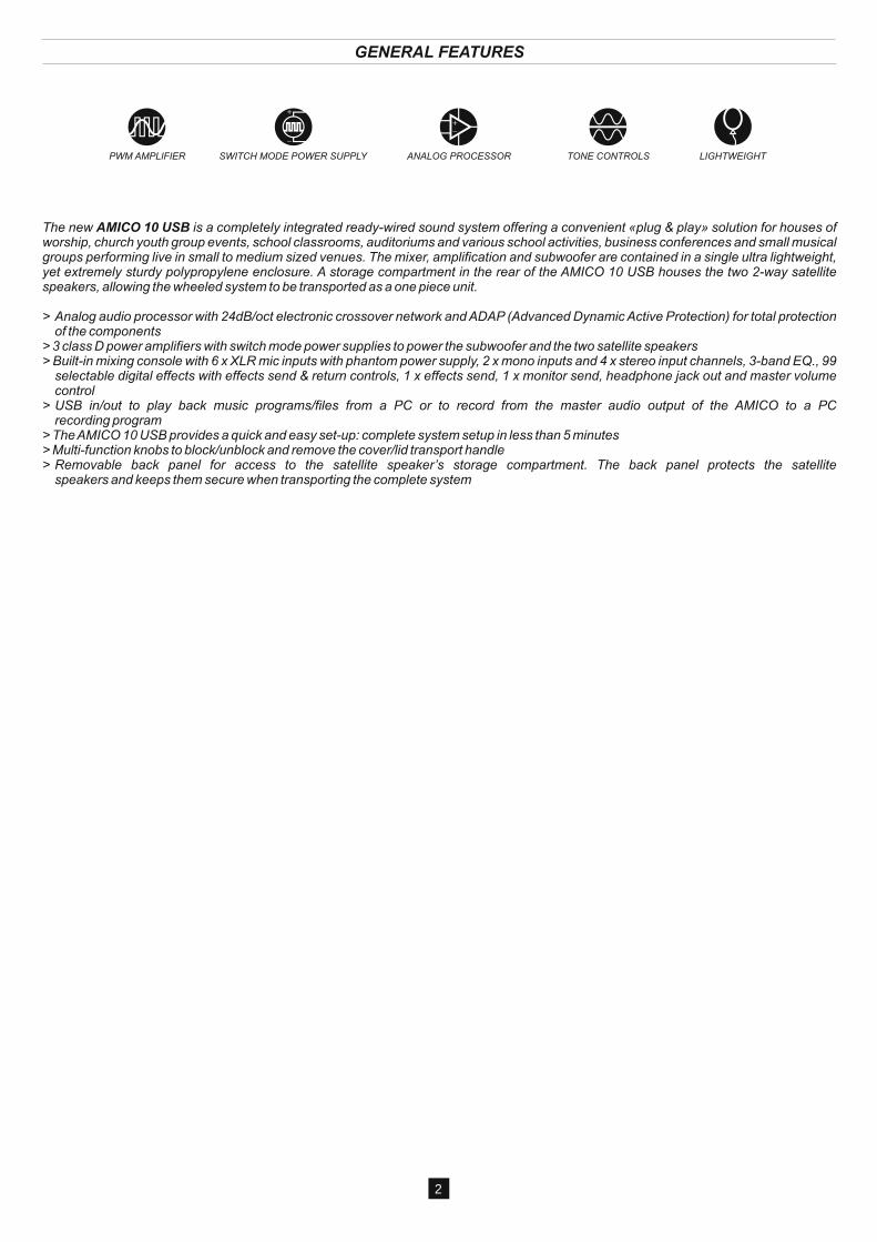
PWM AMPLIFIER SWITCH MODE POWER SUPPLY ANALOG PROCESSOR TONE CONTROLS LIGHTWEIGHT
The new AMICO 10 USB is a completely integrated ready-wired sound system offering a convenient «plug & play» solution for houses of worship, church youth group events, school classrooms, auditoriums and various school activities, business conferences and small musical groups performing live in small to medium sized venues. The mixer, amplification and subwoofer are contained in a single ultra lightweight, yet extremely sturdy polypropylene enclosure. A storage compartment in the rear of the AMICO 10 USB houses the two 2-way satellite speakers, allowing the wheeled system to be transported as a one piece unit.
> Analog audio processor with 24dB/oct electronic crossover network and ADAP (Advanced Dynamic Active Protection) for total protection of the components
> 3 class D power amplifiers with switch mode power supplies to power the subwoofer and the two satellite speakers> Built-in mixing console with 6 x XLR mic inputs with phantom power supply, 2 x mono inputs and 4 x stereo input channels, 3-band EQ., 99
selectable digital effects with effects send & return controls, 1 x effects send, 1 x monitor send, headphone jack out and master volume control
> USB in/out to play back music programs/files from a PC or to record from the master audio output of the AMICO to a PC recording program
> The AMICO 10 USB provides a quick and easy set-up: complete system setup in less than 5 minutes> Multi-function knobs to block/unblock and remove the cover/lid transport handle> Removable back panel for access to the satellite speaker’s storage compartment. The back panel protects the satellite
speakers and keeps them secure when transporting the complete system
2
GENERAL FEATURES
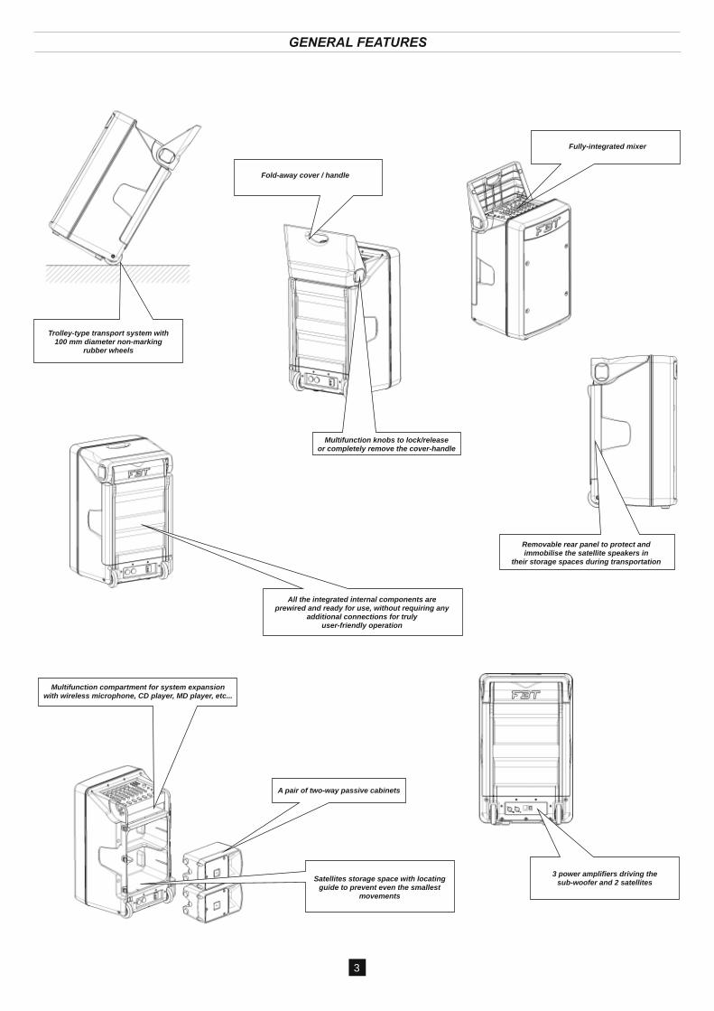
Fully-integrated mixer
Fold-away cover / handle
Trolley-type transport system with100 mm diameter non-marking
rubber wheels
Multifunction knobs to lock/releaseor completely remove the cover-handle
Removable rear panel to protect andimmobilise the satellite speakers in
their storage spaces during transportation
All the integrated internal components areprewired and ready for use, without requiring any
additional connections for truly user-friendly operation
Multifunction compartment for system expansionwith wireless microphone, CD player, MD player, etc...
A pair of two-way passive cabinets
Satellites storage space with locatingguide to prevent even the smallest
movements
3
O
3 power amplifiers driving the sub-woofer and 2 satellites
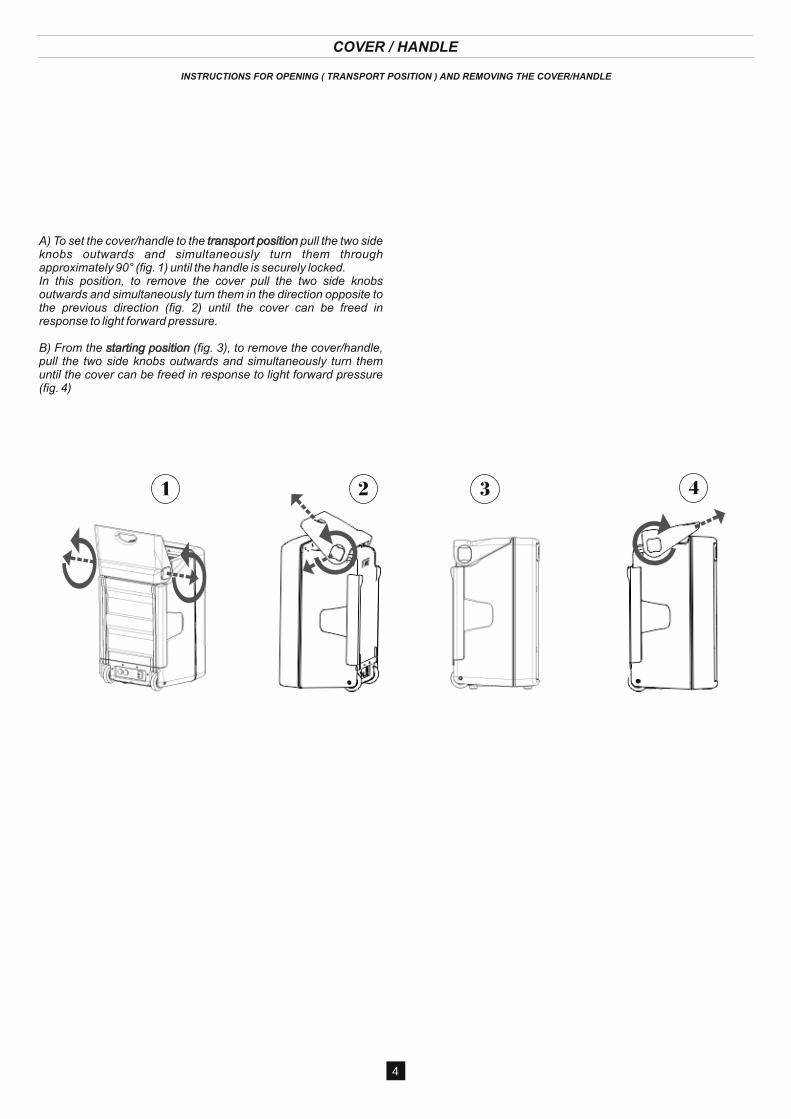
COVER / HANDLE
INSTRUCTIONS FOR OPENING ( TRANSPORT POSITION ) AND REMOVING THE COVER/HANDLE
431 2
4
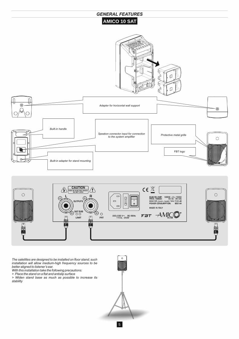
GENERAL FEATURES
Speakon connector input for connectionto the system amplifier
Adapter for horizontal wall support
Built-in handle
Built-in adapter for stand mounting
FBT logo
Protective metal grille
5
AMICO 10 SAT
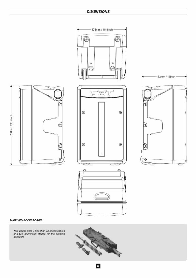
DIMENSIONS
6
SUPPLIED ACCESSORIES
CONNECTORS
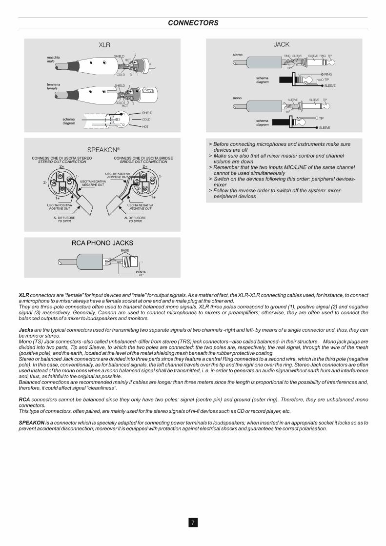
XLR connectors are “female” for input devices and “male” for output signals. As a matter of fact, the XLR-XLR connecting cables used, for instance, to connect a microphone to a mixer always have a female socket at one end and a male plug at the other end.They are three-pole connectors often used to transmit balanced mono signals. XLR three poles correspond to ground (1), positive signal (2) and negative signal (3) respectively. Generally, Cannon are used to connect microphones to mixers or preamplifiers; otherwise, they are often used to connect the balanced outputs of a mixer to loudspeakers and monitors.
Jacks are the typical connectors used for transmitting two separate signals of two channels -right and left- by means of a single connector and, thus, they can be mono or stereo. Mono (TS) Jack connectors -also called unbalanced- differ from stereo (TRS) jack connectors –also called balanced- in their structure. Mono jack plugs are divided into two parts, Tip and Sleeve, to which the two poles are connected: the two poles are, respectively, the real signal, through the wire of the mesh (positive pole), and the earth, located at the level of the metal shielding mesh beneath the rubber protective coating. Stereo or balanced Jack connectors are divided into three parts since they feature a central Ring connected to a second wire, which is the third pole (negative pole). In this case, conventionally, as for balanced signals, the left channel travels over the tip and the right one over the ring. Stereo Jack connectors are often used instead of the mono ones when a mono balanced signal shall be transmitted, i. e. in order to generate an audio signal without earth hum and interference and, thus, as faithful to the original as possible.Balanced connections are recommended mainly if cables are longer than three meters since the length is proportional to the possibility of interferences and, therefore, it could affect signal “cleanliness”.
RCA connectors cannot be balanced since they only have two poles: signal (centre pin) and ground (outer ring). Therefore, they are unbalanced mono connectors.This type of connectors, often paired, are mainly used for the stereo signals of hi-fi devices such as CD or record player, etc.
SPEAKON is a connector which is specially adapted for connecting power terminals to loudspeakers; when inserted in an appropriate socket it locks so as to prevent accidental disconnection; moreover it is equipped with protection against electrical shocks and guarantees the correct polarisation.
7
stereo
mono
schemadiagram
schemadiagram
RCA PHONO JACKS
CONNESSIONE DI USCITA STEREO CONNESSIONE DI USCITA BRIDGE
AL DIFFUSORETO SPKR
AL DIFFUSORETO SPKR
USCITA POSITIVAPOSITIVE OUT
USCITA NEGATIVANEGATIVE OUT
USCITA NEGATIVANEGATIVE OUT
USCITA POSITIVAPOSITIVE OUT
STEREO OUT CONNECTION BRIDGE OUT CONNECTION
maschiomale
femminafemale
schemadiagram
BASE
PUNTATIP
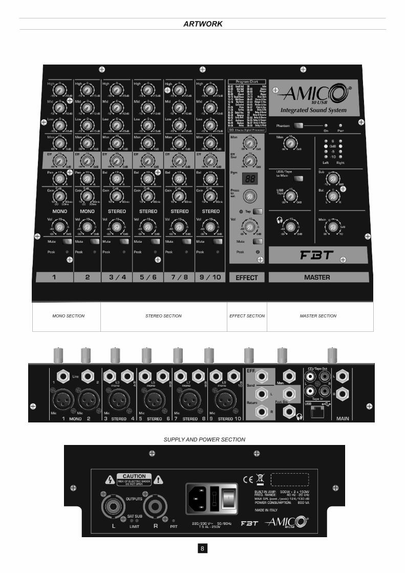
MONO SECTION STEREO SECTION EFFECT SECTION MASTER SECTION
SUPPLY AND POWER SECTION
8
ARTWORK
CONTROLS & FUNCTIONS
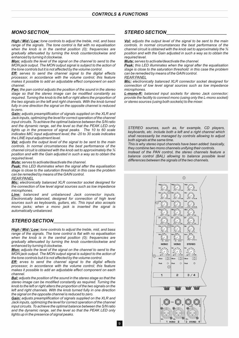
MONO SECTION_________________________________
High / Mid / Low: range of the signals. The tone control is flat with no equalisation when the knob is in the central position (0); frequencies are gradually attenuated by turning the knob counterclockwise and enhanced by turning it clockwise.Mon: adjusts the level of the signal on the channel to send to the MON jack output. The MON output signal is subject to the action of the tone controls but it is not affected by the volume control.Eff: serves to send the channel signal to the digital effects processor, in accordance with the volume control; this feature makes it possible to add an adjustable effect component on each channel.Pan: the pan control adjusts the position of the sound in the stereo stage so that the stereo image can be modified constantly as required. Turning the knob to the left or right alters the proportion of the two signals on the left and right channels. With the knob turned fully in one direction the signal on the opposite channel is reduced to zero.Gain: adjusts preamplification of signals supplied on the XLR and Jack inputs, optimizing the level for correct operation of the channel input circuits. To achieve the optimal balance between the S/N ratio and the dynamic range, set the level so that the PEAK LED only lights up in the presence of signal peaks. The 10 to 60 scale indicates MIC input adjustment level; the -20 to 30 scale indicates the LINE input adjustment level.Vol: adjusts the output level of the signal to be sent to the main controls. In normal circumstances the best performance of the channel circuit is obtained with the knob set to approximately the ¾ position and with the Gain adjusted in such a way as to obtain the required level.Mute: serves to activate/deactivate the channel.Peak: this LED illuminates when the signal after the equalisation stage is close to the saturation threshold: in this case the problem can be remedied by means of the GAIN control.REAR PANELMic: electronically balanced XLR connector socket designed for the connection of low level signal sources such as low impedance microphones.Line: balanced and unbalanced Jack connector inputs. Electronically balanced, designed for connection of high level sources such as keyboards, guitars, etc. This input also accepts mono jacks; when a mono jack is inserted the signal is automatically unbalanced.
STEREO SECTION______________________________
High / Mid / Low: tone controls to adjust the treble, mid, and bass range of the signals. The tone control is flat with no equalisation when the knob is in the central position (0); frequencies are gradually attenuated by turning the knob counterclockwise and enhanced by turning it clockwise.Mon: adjusts the level of the signal on the channel to send to the MON jack output. The MON output signal is subject to the action of the tone controls but it is not affected by the volume control.Eff: erves to send the channel signal to the digital effects processor, in accordance with the volume control; this feature makes it possible to add an adjustable effect component on each channel.Bal: adjusts the position of the sound in the stereo stage so that the stereo image can be modified constantly as required. Turning the knob to the left or right alters the proportion of the two signals on the left and right channels. With the knob turned fully in one direction the signal on the opposite channel is reduced to zero.Gain: adjusts preamplification of signals supplied on the XLR and Jack inputs, optimizing the level for correct operation of the channel input circuits. To achieve the optimal balance between the S/N ratio and the dynamic range, set the level so that the PEAK LED only lights up in the presence of signal peaks.
tone controls to adjust the treble, mid, and bass
STEREO SECTION______________________________
Vol: adjusts the output level of the signal to be sent to the main controls. In normal circumstances the best performance of the channel circuit is obtained with the knob set to approximately the ¾ position and with the Gain adjusted in such a way as to obtain the required level.Mute: serves to activate/deactivate the channel.Peak: this LED illuminates when the signal after the equalisation stage is close to the saturation threshold: in this case the problem can be remedied by means of the GAIN control.REAR PANELMic: electronically balanced XLR connector socket designed for connection of low level signal sources such as low impedance microphones.L-mono-R: balanced input sockets for stereo Jack connector; provide the facility to connect mono (using only the L-mono socket) or stereo sources (using both sockets) to the mixer.
STEREO sources, such as, for example, CD players, keyboards, etc. include both a left and a right channel which shall necessarily be managed by controls allowing to adjust both signals at the same time.This is why stereo input channels have been added: basically, they combine two mono channels unifying their controls.Instead of the PAN control, the stereo channels feature a balance control (BAL) allowing to balance possible level differences between the signals of the two channels.
9
CONTROLS & FUNCTIONS
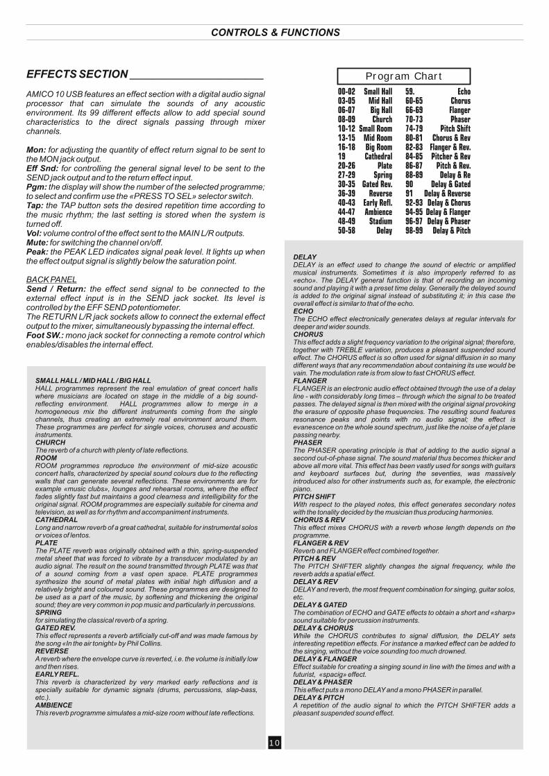
EFFECTS SECTION _____________________________
AMICO 10 USB features an effect section with a digital audio signal processor that can simulate the sounds of any acoustic environment. Its 99 different effects allow to add special sound characteristics to the direct signals passing through mixer channels.
Mon: for adjusting the quantity of effect return signal to be sent to the MON jack output.Eff Snd: for controlling the general signal level to be sent to the SEND jack output and to the return effect input.Pgm: the display will show the number of the selected programme; to select and confirm use the «PRESS TO SEL» selector switch.Tap: the TAP button sets the desired repetition time according to the music rhythm; the last setting is stored when the system is turned off.Vol: volume control of the effect sent to the MAIN L/R outputs.Mute: for switching the channel on/off.Peak: the PEAK LED indicates signal peak level. It lights up when the effect output signal is slightly below the saturation point.
BACK PANELSend / Return: the effect send signal to be connected to the external effect input is in the SEND jack socket. Its level is controlled by the EFF SEND potentiometer.The RETURN L/R jack sockets allow to connect the external effect output to the mixer, simultaneously bypassing the internal effect.Foot SW.: mono jack socket for connecting a remote control which enables/disables the internal effect.
00-0203-0506-0708-0910-1213-1516-181920-2627-2930-3536-3940-4344-4748-4950-58
Small HallMid HallBig HallChurch
Small RoomMid RoomBig RoomCathedral
PlateSpring
Gated Rev.Reverse
Early Refl.Ambience
StadiumDelay
59.60-6566-6970-7374-7980-8182-8384-8586-8788-89909192-9394-9596-9798-99
EchoChorusFlangerPhaser
Pitch ShiftChorus & Rev
Flanger & Rev.Pitcher & Rev
Pitch & Rev.Delay & Re
Delay & GatedDelay & ReverseDelay & ChorusDelay & FlangerDelay & Phaser
Delay & Pitch
Program Chart
SMALL HALL / MID HALL / BIG HALLHALL programmes represent the real emulation of great concert halls where musicians are located on stage in the middle of a big sound-reflecting environment. HALL programmes allow to merge in a homogeneous mix the different instruments coming from the single channels, thus creating an extremely real environment around them. These programmes are perfect for single voices, choruses and acoustic instruments.CHURCHThe reverb of a church with plenty of late reflections.ROOMROOM programmes reproduce the environment of mid-size acoustic concert halls, characterized by special sound colours due to the reflecting walls that can generate several reflections. These environments are for example «music clubs», lounges and rehearsal rooms, where the effect fades slightly fast but maintains a good clearness and intelligibility for the original signal. ROOM programmes are especially suitable for cinema and television, as well as for rhythm and accompaniment instruments.CATHEDRALLong and narrow reverb of a great cathedral, suitable for instrumental solos or voices of lentos.PLATEThe PLATE reverb was originally obtained with a thin, spring-suspended metal sheet that was forced to vibrate by a transducer modulated by an audio signal. The result on the sound transmitted through PLATE was that of a sound coming from a vast open space. PLATE programmes synthesize the sound of metal plates with initial high diffusion and a relatively bright and coloured sound. These programmes are designed to be used as a part of the music, by softening and thickening the original sound; they are very common in pop music and particularly in percussions.SPRINGfor simulating the classical reverb of a spring.GATED REV.This effect represents a reverb artificially cut-off and was made famous by the song «In the air tonight» by Phil Collins.REVERSEA reverb where the envelope curve is reverted, i.e. the volume is initially low and then rises.EARLY REFL.This reverb is characterized by very marked early reflections and is specially suitable for dynamic signals (drums, percussions, slap-bass, etc.).AMBIENCEThis reverb programme simulates a mid-size room without late reflections.
DELAYDELAY is an effect used to change the sound of electric or amplified musical instruments. Sometimes it is also improperly referred to as «echo». The DELAY general function is that of recording an incoming sound and playing it with a preset time delay. Generally the delayed sound is added to the original signal instead of substituting it; in this case the overall effect is similar to that of the echo.ECHOThe ECHO effect electronically generates delays at regular intervals for deeper and wider sounds.CHORUSThis effect adds a slight frequency variation to the original signal; therefore, together with TREBLE variation, produces a pleasant suspended sound effect. The CHORUS effect is so often used for signal diffusion in so many different ways that any recommendation about containing its use would be vain. The modulation rate is from slow to fast CHORUS effect.FLANGERFLANGER is an electronic audio effect obtained through the use of a delay line - with considerably long times – through which the signal to be treated passes. The delayed signal is then mixed with the original signal provoking the erasure of opposite phase frequencies. The resulting sound features resonance peaks and points with no audio signal; the effect is evanescence on the whole sound spectrum, just like the noise of a jet plane passing nearby.PHASERThe PHASER operating principle is that of adding to the audio signal a second out-of-phase signal. The sound material thus becomes thicker and above all more vital. This effect has been vastly used for songs with guitars and keyboard surfaces but, during the seventies, was massively introduced also for other instruments such as, for example, the electronic piano.PITCH SHIFTWith respect to the played notes, this effect generates secondary notes with the tonality decided by the musician thus producing harmonies.CHORUS & REVThis effect mixes CHORUS with a reverb whose length depends on the programme.FLANGER & REVReverb and FLANGER effect combined together.PITCH & REVThe PITCH SHIFTER slightly changes the signal frequency, while the reverb adds a spatial effect.DELAY & REVDELAY and reverb, the most frequent combination for singing, guitar solos, etc.DELAY & GATEDThe combination of ECHO and GATE effects to obtain a short and «sharp» sound suitable for percussion instruments.DELAY & CHORUS While the CHORUS contributes to signal diffusion, the DELAY sets interesting repetition effects. For instance a marked effect can be added to the singing, without the voice sounding too much drowned.DELAY & FLANGEREffect suitable for creating a singing sound in line with the times and with a futurist, «spacig» effect.DELAY & PHASERThis effect puts a mono DELAY and a mono PHASER in parallel.DELAY & PITCHA repetition of the audio signal to which the PITCH SHIFTER adds a pleasant suspended sound effect.
10
CONTROLS & FUNCTIONS
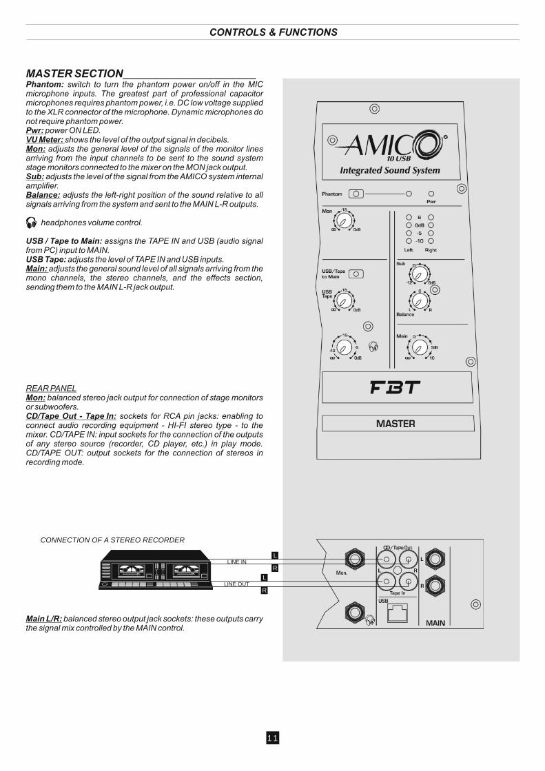
MASTER SECTION_____________________________Phantom: switch to turn the phantom power on/off in the MIC microphone inputs. The greatest part of professional capacitor microphones requires phantom power, i.e. DC low voltage supplied to the XLR connector of the microphone. Dynamic microphones do not require phantom power.Pwr: VU Meter: shows the level of the output signal in decibels.Mon: adjusts the general level of the signals of the monitor lines arriving from the input channels to be sent to the sound system stage monitors connected to the mixer on the MON jack output.Sub: adjusts the level of the signal from the AMICO system internal amplifier.Balance: adjusts the left-right position of the sound relative to all signals arriving from the system and sent to the MAIN L-R outputs.
headphones volume control.
USB / Tape to Main: assigns the TAPE IN and USB (audio signal from PC) input to MAIN. USB Tape: adjusts the level of TAPE IN and USB inputs. Main: adjusts the general sound level of all signals arriving from the mono channels, the stereo channels, and the effects section, sending them to the MAIN L-R jack output.
REAR PANELMon: balanced stereo jack output for connection of stage monitors or subwoofers.CD/Tape Out - Tape In: sockets for RCA pin jacks: enabling to connect audio recording equipment - HI-FI stereo type - to the mixer. CD/TAPE IN: input sockets for the connection of the outputs of any stereo source (recorder, CD player, etc.) in play mode. CD/TAPE OUT: output sockets for the connection of stereos in recording mode.
Main L/R: balanced stereo output jack sockets: these outputs carry the signal mix controlled by the MAIN control.
power ON LED.
11
LINE IN
LINE OUT
L
R
L
R
CONNECTION OF A STEREO RECORDER
USB INTERFACE
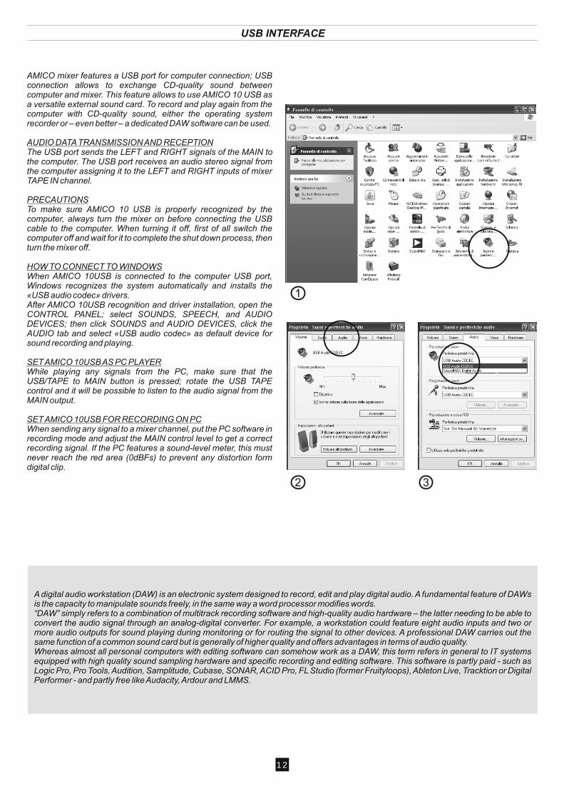
AMICO mixer features a USB port for computer connection; USB connection allows to exchange CD-quality sound between computer and mixer. This feature allows to use AMICO 10 USB as a versatile external sound card. To record and play again from the computer with CD-quality sound, either the operating system recorder or – even better – a dedicated DAW software can be used.
AUDIO DATA TRANSMISSION AND RECEPTION The USB port sends the LEFT and RIGHT signals of the MAIN to the computer. The USB port receives an audio stereo signal from the computer assigning it to the LEFT and RIGHT inputs of mixer TAPE IN channel.
PRECAUTIONSTo make sure AMICO 10 USB is properly recognized by the computer, always turn the mixer on before connecting the USB cable to the computer. When turning it off, first of all switch the computer off and wait for it to complete the shut down process, then turn the mixer off.
HOW TO CONNECT TO WINDOWSWhen AMICO 10USB is connected to the computer USB port, Windows recognizes the system automatically and installs the «USB audio codec» drivers. After AMICO 10USB recognition and driver installation, open the CONTROL PANEL; select SOUNDS, SPEECH, and AUDIO DEVICES; then click SOUNDS and AUDIO DEVICES, click the AUDIO tab and select «USB audio codec» as default device for sound recording and playing.
SET AMICO 10USB AS PC PLAYERWhile playing any signals from the PC, make sure that the USB/TAPE to MAIN button is pressed; rotate the USB TAPE control and it will be possible to listen to the audio signal from the MAIN output.
SET AMICO 10USB FOR RECORDING ON PCWhen sending any signal to a mixer channel, put the PC software in recording mode and adjust the MAIN control level to get a correct recording signal. If the PC features a sound-level meter, this must never reach the red area (0dBFs) to prevent any distortion form digital clip.
1
2 3
A digital audio workstation (DAW) is an electronic system designed to record, edit and play digital audio. A fundamental feature of DAWs is the capacity to manipulate sounds freely, in the same way a word processor modifies words.“DAW” simply refers to a combination of multitrack recording software and high-quality audio hardware – the latter needing to be able to convert the audio signal through an analog-digital converter. For example, a workstation could feature eight audio inputs and two or more audio outputs for sound playing during monitoring or for routing the signal to other devices. A professional DAW carries out the same function of a common sound card but is generally of higher quality and offers advantages in terms of audio quality.Whereas almost all personal computers with editing software can somehow work as a DAW, this term refers in general to IT systems equipped with high quality sound sampling hardware and specific recording and editing software. This software is partly paid - such as Logic Pro, Pro Tools, Audition, Samplitude, Cubase, SONAR, ACID Pro, FL Studio (former Fruityloops), Ableton Live, Tracktion or Digital Performer - and partly free like Audacity, Ardour and LMMS.
12
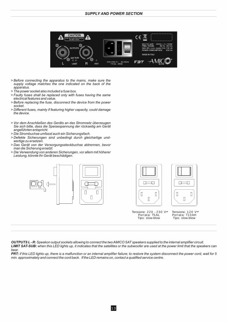
Tensione: 220 - 230 VPortata: T5ALTipo: slow-blow
Tensione: 120 VPortata: T10AHTipo: slow-blow
SUPPLY AND POWER SECTION
OUTPUTS L - R: Speakon output sockets allowing to connect the two AMICO SAT speakers supplied to the internal amplifier circuit.LIMIT SAT-SUB: when this LED lights up, it indicates that the satellites or the subwoofer are used at the power limit that the speakers can bear.PRT: if this LED lights up, there is a malfunction or an internal amplifier failure; to restore the system disconnect the power cord, wait for 5 min. approximately and connect the cord back. If the LED remains on, contact a qualified service centre.
13
BLOCK DIAGRAM
14
Ch
an
ne
l 1
Mic
Lin
e
Ga
in
Ba
l
Hig
hM
idL
ow
Pe
ak
Mu
te
Mo
nit
orV
ol
Eff
Pa
n
V
Me
ter
L
Main
CD
/Ta
pe
To
Ma
inO
n
Ta
pe
Ta
pe
in
V
Me
ter
R
Ba
lan
ce
Mo
nit
or
Ou
t L
Su
b
To
Am
p S
at
L
CD
/Ta
pe
Ou
t
Ou
t R
Ph
on
es
Eff
Se
nd
SO
UN
D P
RO
CE
SS
OR
Fo
ot
Sw
Se
nd
L R
etu
rn
R R
etu
rn
Eff
Mo
n
Eff
Vo
l
Mo
nit
or
Pe
ak M
ute
Pe
ak
Mu
te
Vo
l
Eff
Ba
l
Eff
Vo
l
Ch
an
ne
l 2
= C
ha
nn
el
1
Hig
hM
idL
ow
Ba
l
Mic
Ga
in
Ste
reo
3/4
L3
-mo
no
Hig
hM
idL
ow
R 4
Ste
reo
3/4
= S
tere
o 5
/6 =
Ste
reo
7/8
= S
tere
o 9
/10
Mo
nit
or
Ta
pM
ute
Pe
ak
Pg
m
Pre
ss
to s
el.
US
B
US
B
To
Am
p S
at
R
To
Am
p S
ub
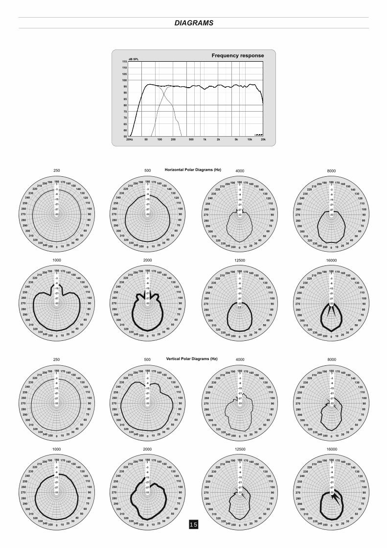
DIAGRAMS
dB SPL115
110
105
100
95
90
85
80
75
70
65
60
5520Hz 50 100 200 500 1k 2k 5k 10k 20k
Frequency response
70
180 170 160150
140
130
120
110
100
90
80
60
50
4030
20100350340330
320
310
300
290
280
270
260
250
240
230
220210
200 190
250
-33
-27
-21
-15
-9
-3
3
500
70
180 170 160150
140
130
120
110
100
90
80
60
50
4030
20100350340330
320
310
300
290
280
270
260
250
240
230
220210
200 190
-33
-27
-21
-15
-9
-3
3
1000
70
180 170 160150
140
130
120
110
100
90
80
60
50
4030
20100350340330
320
310
300
290
280
270
260
250
240
230
220210
200 190
-33
-27
-21
-15
-9
-3
3
2000
70
180 170 160150
140
130
120
110
100
90
80
60
50
4030
20100350340330
320
310
300
290
280
270
260
250
240
230
220210
200 190
-33
-27
-21
-15
-9
-3
3
70
180 170 160150
140
130
120
110
100
90
80
60
50
4030
20100350340330
320
310
300
290
280
270
260
250
240
230
220210
200 190
-33
-27
-21
-15
-9
-3
3
4000
70
180 170 160150
140
130
120
110
100
90
80
60
50
4030
20100350340330
320
310
300
290
280
270
260
250
240
230
220210
200 190
-33
-27
-21
-15
-9
-3
3
8000
70
180 170 160150
140
130
120
110
100
90
80
60
50
4030
20100350340330
320
310
300
290
280
270
260
250
240
230
220210
200 190
-33
-27
-21
-15
-9
-3
3
12500
70
180 170 160150
140
130
120
110
100
90
80
60
50
4030
20100350340330
320
310
300
290
280
270
260
250
240
230
220210
200 190
-33
-27
-21
-15
-9
-3
3
16000
70
180 170 160150
140
130
120
110
100
90
80
60
50
4030
20100350340330
320
310
300
290
280
270
260
250
240
230
220210
200 190
-33
-27
-21
-15
-9
-3
3
250
70
180 170 160150
140
130
120
110
100
90
80
60
50
4030
20100350340330
320
310
300
290
280
270
260
250
240
230
220210
200 190
-33
-27
-21
-15
-9
-3
3
500
70
180 170 160150
140
130
120
110
100
90
80
60
50
4030
20100350340330
320
310
300
290
280
270
260
250
240
230
220210
200 190
-33
-27
-21
-15
-9
-3
3
1000
70
180 170 160150
140
130
120
110
100
90
80
60
50
4030
20100350340330
320
310
300
290
280
270
260
250
240
230
220210
200 190
-33
-27
-21
-15
-9
-3
3
2000
70
180 170 160150
140
130
120
110
100
90
80
60
50
4030
20100350340330
320
310
300
290
280
270
260
250
240
230
220210
200 190
-33
-27
-21
-15
-9
-3
3
4000
70
180 170 160150
140
130
120
110
100
90
80
60
50
4030
20100350340330
320
310
300
290
280
270
260
250
240
230
220210
200 190
-33
-27
-21
-15
-9
-3
3
8000
70
180 170 160150
140
130
120
110
100
90
80
60
50
4030
20100350340330
320
310
300
290
280
270
260
250
240
230
220210
200 190
-33
-27
-21
-15
-9
-3
3
12500
70
180 170 160150
140
130
120
110
100
90
80
60
50
4030
20100350340330
320
310
300
290
280
270
260
250
240
230
220210
200 190
-33
-27
-21
-15
-9
-3
3
16000
Vertical Polar Diagrams (Hz)
Horizontal Polar Diagrams (Hz)
15
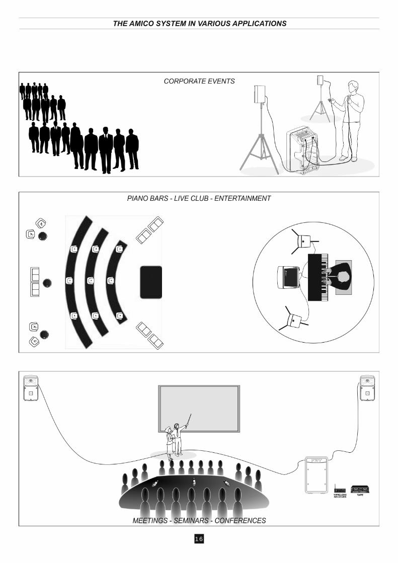
THE AMICO SYSTEM IN VARIOUS APPLICATIONS
16
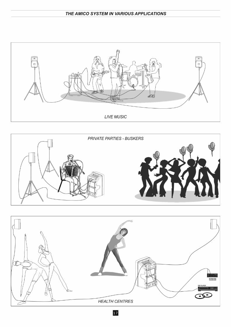
THE AMICO SYSTEM IN VARIOUS APPLICATIONS
17
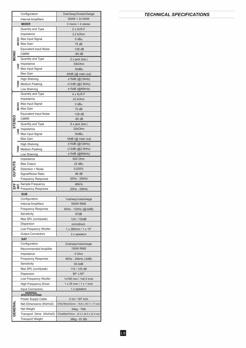
TECHNICAL SPECIFICATIONS
18