Embed Size (px)
Citation preview

Installation and Service ManualLoad Computer 1010 CB

Honeywell Enraf
2000 Northfield Court,
Roswell, GA 30076
U.S.A.
Tel: +1 770 475 1900
Email: [email protected]
www.honeywellenraf.com
4418027 - Revision 1
April 2010
© 2010 Honeywell International Inc.
iii Model 1010 Application Pack CB Part No.: 4418027 - Rev. 1Installation and Service Manual
Table of Contents
CHAPTER 1 Receipt of Equipment
1.1 Checking of Shipment. . . . . . . . . . . . . . . . . . . . . . . . . . . . . . . . . . . . . . . . . 1-1
1.2 Unpacking . . . . . . . . . . . . . . . . . . . . . . . . . . . . . . . . . . . . . . . . . . . . . . . . . . 1-1
1.3 Reporting of Problems . . . . . . . . . . . . . . . . . . . . . . . . . . . . . . . . . . . . . . . . 1-1
CHAPTER 2 Recommended Wiring Practices
2.1 Description. . . . . . . . . . . . . . . . . . . . . . . . . . . . . . . . . . . . . . . . . . . . . . . . . . 2-1
2.2 Shielding . . . . . . . . . . . . . . . . . . . . . . . . . . . . . . . . . . . . . . . . . . . . . . . . . . . 2-1
2.3 Signals . . . . . . . . . . . . . . . . . . . . . . . . . . . . . . . . . . . . . . . . . . . . . . . . . . . . . 2-2
2.4 Cable Ducts . . . . . . . . . . . . . . . . . . . . . . . . . . . . . . . . . . . . . . . . . . . . . . . . . 2-2
2.5 Mains Noise . . . . . . . . . . . . . . . . . . . . . . . . . . . . . . . . . . . . . . . . . . . . . . . . . 2-3
2.6 Locating Interference Problems. . . . . . . . . . . . . . . . . . . . . . . . . . . . . . . . . 2-3
2.7 Ground Loops . . . . . . . . . . . . . . . . . . . . . . . . . . . . . . . . . . . . . . . . . . . . . . . 2-3
2.8 Isolation . . . . . . . . . . . . . . . . . . . . . . . . . . . . . . . . . . . . . . . . . . . . . . . . . . . . 2-4
2.9 Lightning Protection . . . . . . . . . . . . . . . . . . . . . . . . . . . . . . . . . . . . . . . . . . 2-4
2.10 RC Networks for Interference Suppression . . . . . . . . . . . . . . . . . . . . . . . 2-5
CHAPTER 3 Mechanical Installation
3.1 Description. . . . . . . . . . . . . . . . . . . . . . . . . . . . . . . . . . . . . . . . . . . . . . . . . . 3-1
3.2 Location . . . . . . . . . . . . . . . . . . . . . . . . . . . . . . . . . . . . . . . . . . . . . . . . . . . . 3-1
3.3 Mounting . . . . . . . . . . . . . . . . . . . . . . . . . . . . . . . . . . . . . . . . . . . . . . . . . . . 3-1
3.4 Cable Glands . . . . . . . . . . . . . . . . . . . . . . . . . . . . . . . . . . . . . . . . . . . . . . . . 3-1
3.5 Gland Holes . . . . . . . . . . . . . . . . . . . . . . . . . . . . . . . . . . . . . . . . . . . . . . . . . 3-1
3.6 Case Bolts . . . . . . . . . . . . . . . . . . . . . . . . . . . . . . . . . . . . . . . . . . . . . . . . . . 3-2
3.7 Enclosure - General Information . . . . . . . . . . . . . . . . . . . . . . . . . . . . . . . . 3-2
3.8 Ambient Temperature . . . . . . . . . . . . . . . . . . . . . . . . . . . . . . . . . . . . . . . . . 3-2
CHAPTER 4 Testing and Commissioning
4.1 Description. . . . . . . . . . . . . . . . . . . . . . . . . . . . . . . . . . . . . . . . . . . . . . . . . . 4-1
4.2 Pre-Power-Up Check . . . . . . . . . . . . . . . . . . . . . . . . . . . . . . . . . . . . . . . . . . 4-1
4.3 Hardware Test . . . . . . . . . . . . . . . . . . . . . . . . . . . . . . . . . . . . . . . . . . . . . . . 4-1
CHAPTER 5 Hardware Test
5.1 Description. . . . . . . . . . . . . . . . . . . . . . . . . . . . . . . . . . . . . . . . . . . . . . . . . . 5-1
5.2 Hardware Test Program . . . . . . . . . . . . . . . . . . . . . . . . . . . . . . . . . . . . . . . 5-1
5.3 Entering Hardware Test Mode . . . . . . . . . . . . . . . . . . . . . . . . . . . . . . . . . . 5-1
5.4 Slot A—Power Supply Card . . . . . . . . . . . . . . . . . . . . . . . . . . . . . . . . . . . . 5-2
5.5 Slot B—Output Card . . . . . . . . . . . . . . . . . . . . . . . . . . . . . . . . . . . . . . . . . . 5-4
5.6 Slot C—I/P Card . . . . . . . . . . . . . . . . . . . . . . . . . . . . . . . . . . . . . . . . . . . . . 5-4
5.6.1 Flow Total Inputs . . . . . . . . . . . . . . . . . . . . . . . . . . . . . . . . . . . . . . . . . . . . . . 5-4
5.6.2 Flow Frequency Inputs . . . . . . . . . . . . . . . . . . . . . . . . . . . . . . . . . . . . . . . . . 5-5
iv Model 1010 Application Pack CB Part No.: 4418027 - Rev. 1Installation and Service Manual
5.6.3 Temperature RTD/4-20 mA Inputs. . . . . . . . . . . . . . . . . . . . . . . . . . . . . . . . . 5-5
5.6.4 Press/Dens 4-20 mA Inputs. . . . . . . . . . . . . . . . . . . . . . . . . . . . . . . . . . . . . . 5-6
5.6.5 Opto Outputs . . . . . . . . . . . . . . . . . . . . . . . . . . . . . . . . . . . . . . . . . . . . . . . . . 5-7
5.6.6 Switch/Digital Inputs . . . . . . . . . . . . . . . . . . . . . . . . . . . . . . . . . . . . . . . . . . . 5-7
5.7 Slot D—CPU CARD . . . . . . . . . . . . . . . . . . . . . . . . . . . . . . . . . . . . . . . . . . . 5-8
5.7.1 IS Touch Test . . . . . . . . . . . . . . . . . . . . . . . . . . . . . . . . . . . . . . . . . . . . . . . . . 5-8
5.7.2 Touch Channel 1 and 2 Test . . . . . . . . . . . . . . . . . . . . . . . . . . . . . . . . . . . . . 5-8
5.7.3 Touch Input Test . . . . . . . . . . . . . . . . . . . . . . . . . . . . . . . . . . . . . . . . . . . . . . 5-8
5.7.4 RF ID Test . . . . . . . . . . . . . . . . . . . . . . . . . . . . . . . . . . . . . . . . . . . . . . . . . . . 5-8
5.7.5 Com Port Tests . . . . . . . . . . . . . . . . . . . . . . . . . . . . . . . . . . . . . . . . . . . . . . . 5-8
5.7.6 Communications Receive (Rx) and Echo . . . . . . . . . . . . . . . . . . . . . . . . . . . 5-8
5.7.7 Communications Send and Receive (Rx) . . . . . . . . . . . . . . . . . . . . . . . . . . . 5-9
5.7.8 4 to 20MA Outputs. . . . . . . . . . . . . . . . . . . . . . . . . . . . . . . . . . . . . . . . . . . . . 5-9
5.8 Additive Lines . . . . . . . . . . . . . . . . . . . . . . . . . . . . . . . . . . . . . . . . . . . . . . . 5-9
5.9 Keyboard . . . . . . . . . . . . . . . . . . . . . . . . . . . . . . . . . . . . . . . . . . . . . . . . . . . 5-9
5.10 NexKey Test . . . . . . . . . . . . . . . . . . . . . . . . . . . . . . . . . . . . . . . . . . . . . . . . . 5-9
CHAPTER 6 General Servicing
6.1 Description. . . . . . . . . . . . . . . . . . . . . . . . . . . . . . . . . . . . . . . . . . . . . . . . . . 6-1
6.2 Important Notes . . . . . . . . . . . . . . . . . . . . . . . . . . . . . . . . . . . . . . . . . . . . . . 6-1
6.3 Tools Required. . . . . . . . . . . . . . . . . . . . . . . . . . . . . . . . . . . . . . . . . . . . . . . 6-1
6.4 Module Replacement. . . . . . . . . . . . . . . . . . . . . . . . . . . . . . . . . . . . . . . . . . 6-2
6.4.1 Main Electronics . . . . . . . . . . . . . . . . . . . . . . . . . . . . . . . . . . . . . . . . . . . . . . 6-2
6.4.2 Display Electronics . . . . . . . . . . . . . . . . . . . . . . . . . . . . . . . . . . . . . . . . . . . . 6-4
6.5 Card (PCB) Replacement . . . . . . . . . . . . . . . . . . . . . . . . . . . . . . . . . . . . . . 6-4
CHAPTER 7 Automated Proving Mode
7.1 Automated Proving on Straight Loading Arms . . . . . . . . . . . . . . . . . . . . 7-2
7.2 Automated Proving on Blending Arms . . . . . . . . . . . . . . . . . . . . . . . . . . . 7-5
7.3 Internal Additive Meter Proving or Calibration . . . . . . . . . . . . . . . . . . . . . 7-8
CHAPTER 8 Firmware Update
8.1 Description. . . . . . . . . . . . . . . . . . . . . . . . . . . . . . . . . . . . . . . . . . . . . . . . . . 8-1
8.2 Tools Required. . . . . . . . . . . . . . . . . . . . . . . . . . . . . . . . . . . . . . . . . . . . . . . 8-1
8.3 Instrument Configuration . . . . . . . . . . . . . . . . . . . . . . . . . . . . . . . . . . . . . . 8-1
8.4 Updating the Firmware . . . . . . . . . . . . . . . . . . . . . . . . . . . . . . . . . . . . . . . . 8-1
8.5 Trouble Shooting Firmware Updates . . . . . . . . . . . . . . . . . . . . . . . . . . . . . 8-7
8.5.1 Time-outs. . . . . . . . . . . . . . . . . . . . . . . . . . . . . . . . . . . . . . . . . . . . . . . . . . . . 8-7
8.5.2 Comms Test Failure. . . . . . . . . . . . . . . . . . . . . . . . . . . . . . . . . . . . . . . . . . . . 8-7
8.5.3 Incorrect Checksum. . . . . . . . . . . . . . . . . . . . . . . . . . . . . . . . . . . . . . . . . . . . 8-7
8.5.4 Communications failure during download . . . . . . . . . . . . . . . . . . . . . . . . . . . 8-8
CHAPTER 9 Trouble Shooting
9.1 Description. . . . . . . . . . . . . . . . . . . . . . . . . . . . . . . . . . . . . . . . . . . . . . . . . . 9-1
v Model 1010 Application Pack CB Part No.: 4418027 - Rev. 1Installation and Service Manual
9.2 Wiring . . . . . . . . . . . . . . . . . . . . . . . . . . . . . . . . . . . . . . . . . . . . . . . . . . . . . . 9-1
9.3 Power Supplies . . . . . . . . . . . . . . . . . . . . . . . . . . . . . . . . . . . . . . . . . . . . . . 9-1
9.4 Emergency Stop . . . . . . . . . . . . . . . . . . . . . . . . . . . . . . . . . . . . . . . . . . . . . 9-2
9.5 Pulser Error . . . . . . . . . . . . . . . . . . . . . . . . . . . . . . . . . . . . . . . . . . . . . . . . . 9-2
9.6 No Flow Timeout Error . . . . . . . . . . . . . . . . . . . . . . . . . . . . . . . . . . . . . . . . 9-2
9.7 Scully Overfill. . . . . . . . . . . . . . . . . . . . . . . . . . . . . . . . . . . . . . . . . . . . . . . . 9-2
9.8 Internal Additives . . . . . . . . . . . . . . . . . . . . . . . . . . . . . . . . . . . . . . . . . . . . 9-3
Appendix A Dimension Drawing
Glossary

vi Model 1010 Application Pack CB Part No.: 4418027 - Rev. 1Installation and Service Manual
Intentionally left blank.
1 - 1 Model 1010 Application Pack CB Part No.: 4418027 - Rev. 1Installation and Service Manual
CHAPTER 1 RECEIPT OF EQUIPMENT
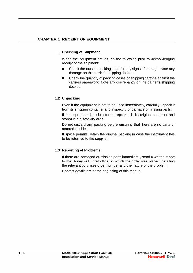
1.1 Checking of Shipment
When the equipment arrives, do the following prior to acknowledgingreceipt of the shipment:
Check the outside packing case for any signs of damage. Note anydamage on the carrier’s shipping docket.
Check the quantity of packing cases or shipping cartons against thecarriers paperwork. Note any discrepancy on the carrier’s shippingdocket.
1.2 Unpacking
Even if the equipment is not to be used immediately, carefully unpack itfrom its shipping container and inspect it for damage or missing parts.
If the equipment is to be stored, repack it in its original container andstored it in a safe dry area.
Do not discard any packing before ensuring that there are no parts ormanuals inside.
If space permits, retain the original packing in case the instrument hasto be returned to the supplier.
1.3 Reporting of Problems
If there are damaged or missing parts immediately send a written reportto the Honeywell Enraf office on which the order was placed, detailingthe relevant purchase order number and the nature of the problem.
Contact details are at the beginning of this manual.

Receipt of Equipment
1 - 2 Model 1010 Application Pack CB Part No.: 4418027 - Rev. 1Installation and Service Manual
Intentionally left blank.
2 - 1 Model 1010 Application Pack CB Part No.: 4418027 - Rev. 1Installation and Service Manual
CHAPTER 2 RECOMMENDED WIRING PRACTICES
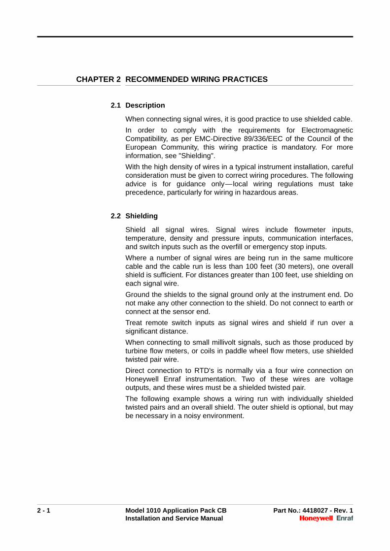
2.1 Description
When connecting signal wires, it is good practice to use shielded cable.
In order to comply with the requirements for ElectromagneticCompatibility, as per EMC-Directive 89/336/EEC of the Council of theEuropean Community, this wiring practice is mandatory. For moreinformation, see "Shielding".
With the high density of wires in a typical instrument installation, carefulconsideration must be given to correct wiring procedures. The followingadvice is for guidance only—local wiring regulations must takeprecedence, particularly for wiring in hazardous areas.
2.2 Shielding
Shield all signal wires. Signal wires include flowmeter inputs,temperature, density and pressure inputs, communication interfaces,and switch inputs such as the overfill or emergency stop inputs.
Where a number of signal wires are being run in the same multicorecable and the cable run is less than 100 feet (30 meters), one overallshield is sufficient. For distances greater than 100 feet, use shielding oneach signal wire.
Ground the shields to the signal ground only at the instrument end. Donot make any other connection to the shield. Do not connect to earth orconnect at the sensor end.
Treat remote switch inputs as signal wires and shield if run over asignificant distance.
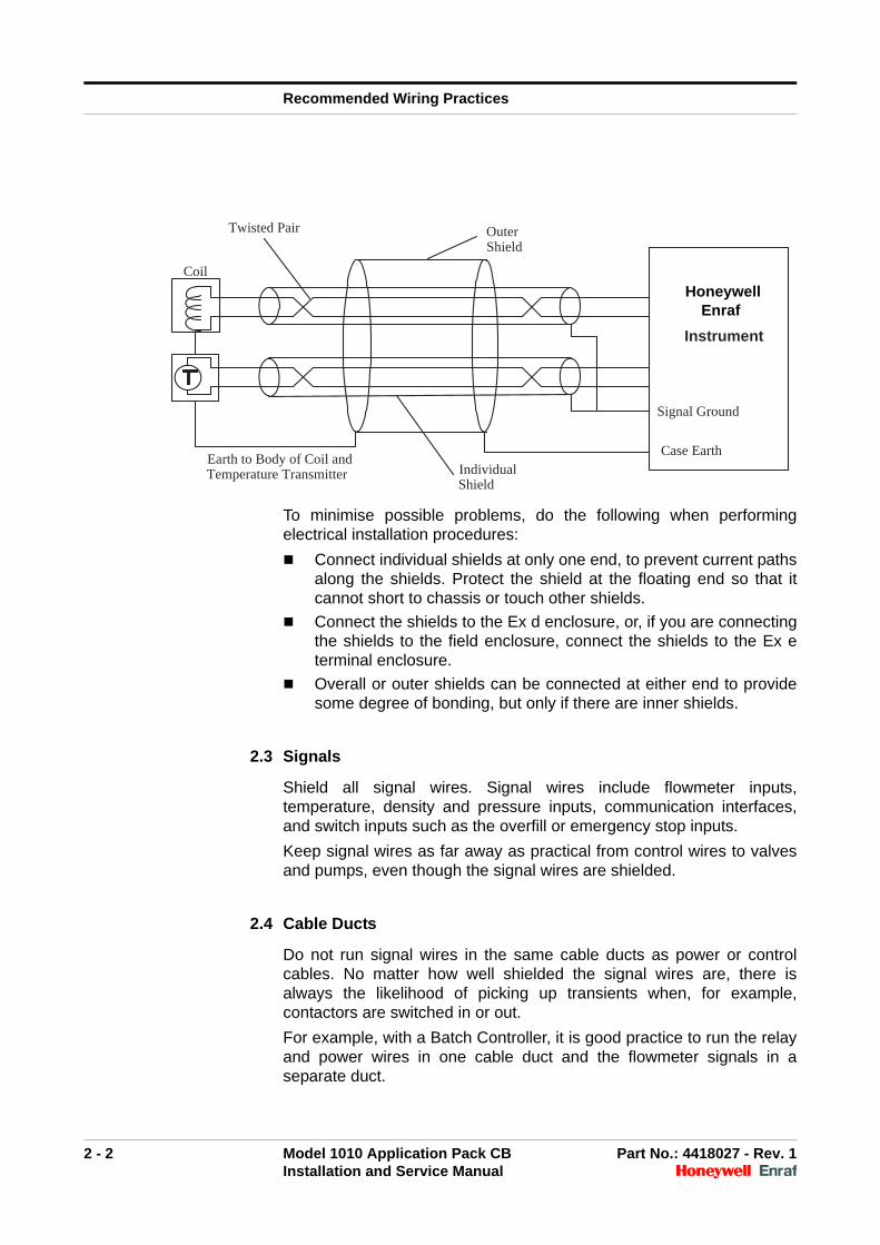
When connecting to small millivolt signals, such as those produced byturbine flow meters, or coils in paddle wheel flow meters, use shieldedtwisted pair wire.
Direct connection to RTD's is normally via a four wire connection onHoneywell Enraf instrumentation. Two of these wires are voltageoutputs, and these wires must be a shielded twisted pair.
The following example shows a wiring run with individually shieldedtwisted pairs and an overall shield. The outer shield is optional, but maybe necessary in a noisy environment.
Recommended Wiring Practices
2 - 2 Model 1010 Application Pack CB Part No.: 4418027 - Rev. 1Installation and Service Manual
To minimise possible problems, do the following when performingelectrical installation procedures:
Connect individual shields at only one end, to prevent current pathsalong the shields. Protect the shield at the floating end so that itcannot short to chassis or touch other shields.
Connect the shields to the Ex d enclosure, or, if you are connectingthe shields to the field enclosure, connect the shields to the Ex eterminal enclosure.
Overall or outer shields can be connected at either end to providesome degree of bonding, but only if there are inner shields.
2.3 Signals
Shield all signal wires. Signal wires include flowmeter inputs,temperature, density and pressure inputs, communication interfaces,and switch inputs such as the overfill or emergency stop inputs.
Keep signal wires as far away as practical from control wires to valvesand pumps, even though the signal wires are shielded.
2.4 Cable Ducts
Do not run signal wires in the same cable ducts as power or controlcables. No matter how well shielded the signal wires are, there isalways the likelihood of picking up transients when, for example,contactors are switched in or out.
For example, with a Batch Controller, it is good practice to run the relayand power wires in one cable duct and the flowmeter signals in aseparate duct.
Coil
Twisted Pair
Outer Shield
Earth to Body of Coil and Temperature Transmitter Individual
Shield
Signal Ground
Case Earth
Honeywell Enraf
Instrument
Recommended Wiring Practices
2 - 3 Model 1010 Application Pack CB Part No.: 4418027 - Rev. 1Installation and Service Manual
2.5 Mains Noise
Mains noise is usually not a problem since the instruments areprotected by varistors and transformers, which shield out mosttransients. The main consideration with mains connections is to ensurea good earth bond is made to the instrument case, and that the livemains wires are not exposed. Refer to the diagram on page 2-2.
2.6 Locating Interference Problems
To find the source of interference, systematically disconnect each inputor output until the noise source is located. There are, unfortunately, nomethods other than trial and error.
There are two ways noise can be induced:
By conduction, for example, spikes on the mains or spikes such asthose produced by switching inductive loads.
By RF emissions, for example pickup from adjoining wires in acable duct, emissions from welders or variable speed motor drivers.
Good wiring practice is the best method of preventing noise.
2.7 Ground Loops
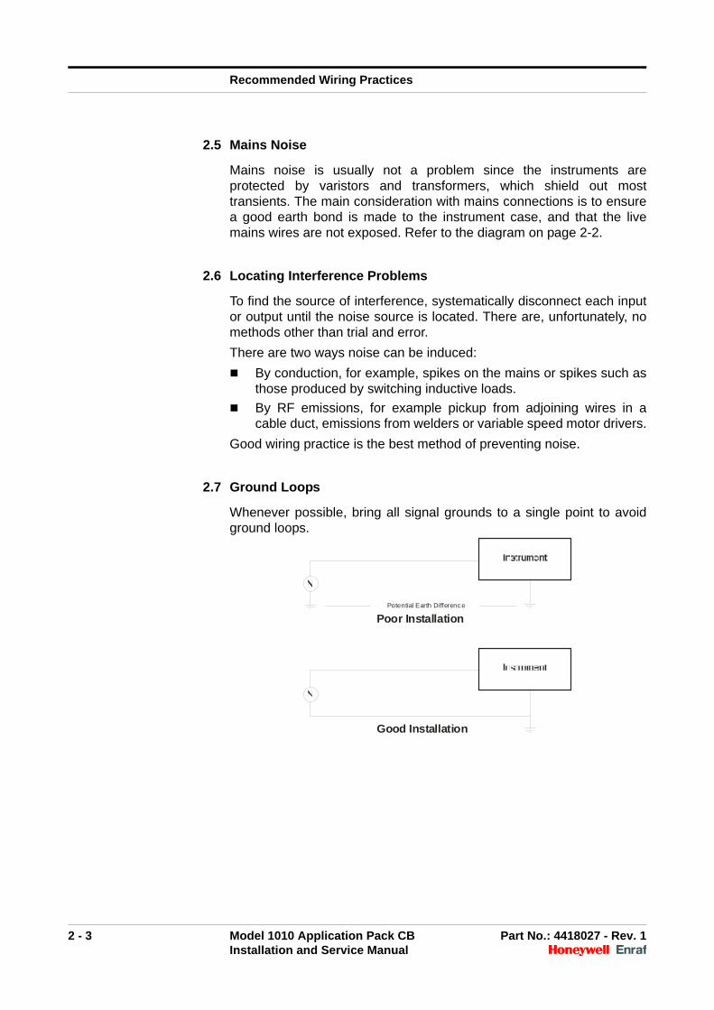
Whenever possible, bring all signal grounds to a single point to avoidground loops.
Potential Earth Difference
Poor Installation
Good Installation
Recommended Wiring Practices
2 - 4 Model 1010 Application Pack CB Part No.: 4418027 - Rev. 1Installation and Service Manual
2.8 Isolation
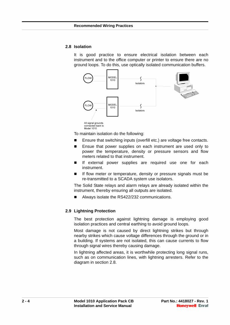
It is good practice to ensure electrical isolation between eachinstrument and to the office computer or printer to ensure there are noground loops. To do this, use optically isolated communication buffers.
To maintain isolation do the following:
Ensure that switching inputs (overfill etc.) are voltage free contacts.
Ensue that power supplies on each instrument are used only topower the temperature, density or pressure sensors and flowmeters related to that instrument.
If external power supplies are required use one for eachinstrument.
If flow meter or temperature, density or pressure signals must bere-transmitted to a SCADA system use isolators.
The Solid State relays and alarm relays are already isolated within theinstrument, thereby ensuring all outputs are isolated.
Always isolate the RS422/232 communications.
2.9 Lightning Protection
The best protection against lightning damage is employing goodisolation practices and central earthing to avoid ground loops.
Most damage is not caused by direct lightning strikes but throughnearby strikes which cause voltage differences through the ground or ina building. If systems are not isolated, this can cause currents to flowthrough signal wires thereby causing damage.
In lightning affected areas, it is worthwhile protecting long signal runs,such as on communication lines, with lightning arresters. Refer to thediagram in section 2.8.

Recommended Wiring Practices
2 - 5 Model 1010 Application Pack CB Part No.: 4418027 - Rev. 1Installation and Service Manual
2.10 RC Networks for Interference Suppression
When driving inductive loads with the electromechanical relay outputs, itis recommended that RC suppression networks (often called“Snubbers”) are used for two reasons:
To limit the amount of electrical noise caused by arcing across thecontacts that may, in extreme cases, cause the microprocessor toact erratically
To protect the relay contacts against premature wear through pitting
RC suppression networks consist of a capacitor and a series resistorand are commonly available in the electrical industry. The values of Rand C are dependent entirely on the load. However, if the user is unsureof the type of snubber to use, values of 0.25 µF and 100 ohms willusually suffice. Use only mains approved RC suppression networks.
The basic principle of operation is that the capacitor prevents a series ofsparks arcing across the contact as the contact breaks. The seriesresistor limits the current through the contact when the contact firstmakes.

Recommended Wiring Practices
2 - 6 Model 1010 Application Pack CB Part No.: 4418027 - Rev. 1Installation and Service Manual
Intentionally left blank.
3 - 1 Model 1010 Application Pack CB Part No.: 4418027 - Rev. 1Installation and Service Manual
CHAPTER 3 MECHANICAL INSTALLATION
3.1 Description
This chapter contains information relating to the mechanical installationof the Model 1010 instrument.
3.2 Location
Enviromental protection in the form of a sun or rain hood is to beprovided if the instrument is installed in the open. The protection fromdirect sunlight is intended to avoid excessive heat build up within theenclosure. The enclosure is rated to IP66/Nema 4x, however protectionfrom inclement weather conditions is beneficial for both servicing andthe long term appearance of the instrument.
Avoid locations where the display is in direct sunlight. This reduces thelong term life span of the display and can make it difficult to read thedisplay.
If possible mount above pipe joins (flanges/barrel unions) to avoidproduct leaking on to the instrument.
Allow room for access to cables (armoured cables have large bendingradii) and to allow the instrument door to swing fully open.
3.3 Mounting
There are four M8 (metric threaded cable entries) or 5/16“UNF (NPTthreaded cable entries) at the bottom and four on top of the enclosureon 90 x 82.7 mm centres.
Make sure the mounting surface can accept the weight of the Model1010—23 kg—and the weight of cable glands and cables whenplanning the mounting hardware.
The base of the enclosure should be approximately 1,200 mm fromfloor level.
3.4 Cable Glands
Use only certified cable glands and install according to the glandmanufacturer’s instructions.
3.5 Gland Holes
Plug unused gland holes with a certified blanking plug.
Mechanical Installation
3 - 2 Model 1010 Application Pack CB Part No.: 4418027 - Rev. 1Installation and Service Manual
3.6 Case Bolts
Securely fasten all bolts that attach the front door of the enclosure to therear case.
Ensure that the sealable bolt to prevent unauthorised access to theinstrument is fitted on the lower right hand side hole on the front door.
3.7 Enclosure - General Information
CAUTION! Incorrect procedures can lead to hazardous situ-ations and may lead to death or injury. When workingwith the instrument, observe the followingprecautions.
Do not drill holes in the enclosure
Electrically earth the enclosure. Attach the earth to the enclosurewhere shown in the diagrams in Appendix A.
Do not open the enclosure if an explosive atmosphere is present,as the electronics contain batteries and/or other charge storagedevices that may cause a spark.
Follow the warnings and precautions given in CHAPTER 6.
Follow site OH&S procedures when servicing equipment.
3.8 Ambient Temperature
Use the enclosures only in ambient temperatures between -10 °C and +60 °C (-40 ºC with optional heater).
4 - 1 Model 1010 Application Pack CB Part No.: 4418027 - Rev. 1Installation and Service Manual
CHAPTER 4 TESTING AND COMMISSIONING
4.1 Description
After installing the instrument, you must commission it. Commissioningis essential, since it helps ensure the correct operation and the reliabilityof the instrument.
Once the instrument is commissioned and all proving is completed theinstrument is to be sealed by the certifying authority via seals on thefront door seal bolt and the W&M button on the side of the instrument ifthe loading system is to be MID compliant.
4.2 Pre-Power-Up Check
Before applying power to the system check all aspects of theinstrument. Give particular attention to the wiring, because the wiring isgenerally the most complex part of the installation.
When checking the wiring give particular attention to the following:
All wiring connections are made to the correct terminals
All wiring is neat and securely fastened in the cable runs
Individual shields are connected at one end only and insulated atthe other end
All shields are connected only to chassis earth, not signal ground
Overall or outer shields are connected to chassis earth
IS safety earths (if used) are connected properly
All low voltage lines (temperature, flow meters, communication,etc.) are physically separated from all high voltage mains wiring
4.3 Hardware Test
Before attempting to deliver product using the instrument use theHardware Test Mode of the instrument to check all valve and pumpcontrols and all inputs apart from flow signals. For more information,see chapter 5 "Hardware Test".

Testing and Commissioning
4 - 2 Model 1010 Application Pack CB Part No.: 4418027 - Rev. 1Installation and Service Manual
Intentionally left blank.
5 - 1 Model 1010 Application Pack CB Part No.: 4418027 - Rev. 1Installation and Service Manual
CHAPTER 5 HARDWARE TEST
5.1 Description
This chapter describes the operation of the built-in hardware testprogram in the instrument.
5.2 Hardware Test Program
To aid commissioning and fault finding the instrument has a built-inhardware test program that allows all of the system inputs and outputsto be exercised.
CAUTION! The built-in hardware test program is extremelypowerful and may operate any outputs, such aspumps or valves, regardless of the status of anyinterlocks, such as the overfill system.
5.3 Entering Hardware Test Mode
To enter Hardware Test Mode
1. Do one of the following:
• Hold the '8' key down for five seconds.After using this method, you cannot alter certain parameters forW&M.
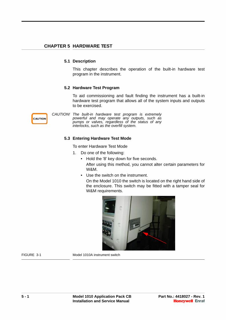
• Use the switch on the instrument.On the Model 1010 the switch is located on the right hand side ofthe enclosure. This switch may be fitted with a tamper seal forW&M requirements.
FIGURE 3-1 Model 1010A instrument switch
Hardware Test
5 - 2 Model 1010 Application Pack CB Part No.: 4418027 - Rev. 1Installation and Service Manual
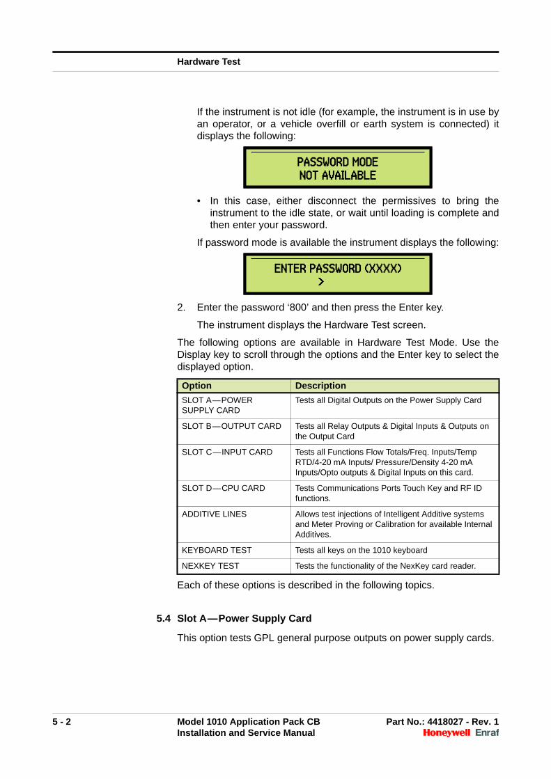
If the instrument is not idle (for example, the instrument is in use byan operator, or a vehicle overfill or earth system is connected) itdisplays the following:
• In this case, either disconnect the permissives to bring theinstrument to the idle state, or wait until loading is complete andthen enter your password.
If password mode is available the instrument displays the following:
2. Enter the password ‘800’ and then press the Enter key.
The instrument displays the Hardware Test screen.
The following options are available in Hardware Test Mode. Use theDisplay key to scroll through the options and the Enter key to select thedisplayed option.
Each of these options is described in the following topics.
5.4 Slot A—Power Supply Card
This option tests GPL general purpose outputs on power supply cards.
PASSWORD MODENOT AVAILABLEPASSWORD MODENOT AVAILABLE
ENTER PASSWORD (XXXX)>
ENTER PASSWORD (XXXX)>
Option Description
SLOT A—POWER SUPPLY CARD
Tests all Digital Outputs on the Power Supply Card
SLOT B—OUTPUT CARD Tests all Relay Outputs & Digital Inputs & Outputs on the Output Card
SLOT C—INPUT CARD Tests all Functions Flow Totals/Freq. Inputs/Temp RTD/4-20 mA Inputs/ Pressure/Density 4-20 mA Inputs/Opto outputs & Digital Inputs on this card.
SLOT D—CPU CARD Tests Communications Ports Touch Key and RF ID functions.
ADDITIVE LINES Allows test injections of Intelligent Additive systems and Meter Proving or Calibration for available Internal Additives.
KEYBOARD TEST Tests all keys on the 1010 keyboard
NEXKEY TEST Tests the functionality of the NexKey card reader.
Hardware Test
5 - 3 Model 1010 Application Pack CB Part No.: 4418027 - Rev. 1Installation and Service Manual
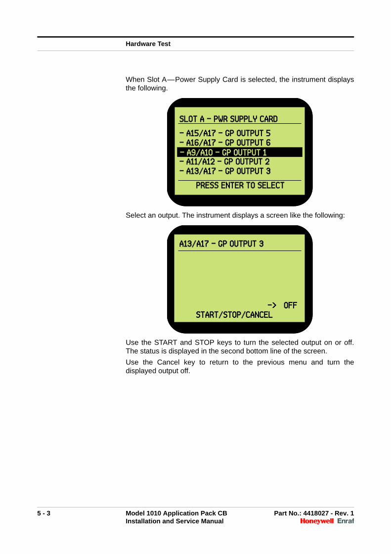
When Slot A—Power Supply Card is selected, the instrument displaysthe following.
Select an output. The instrument displays a screen like the following:
Use the START and STOP keys to turn the selected output on or off.The status is displayed in the second bottom line of the screen.
Use the Cancel key to return to the previous menu and turn thedisplayed output off.
SLOT A - PWR SUPPLY CARD
- A15/A17 - GP OUTPUT 5- A16/A17 - GP OUTPUT 61 - DISPLAY CONTRAST- A11/A12 - GP OUTPUT 2- A13/A17 - GP OUTPUT 3
PRESS ENTER TO SELECT
- A9/A10 - GP OUTPUT 1
SLOT A - PWR SUPPLY CARD
- A15/A17 - GP OUTPUT 5- A16/A17 - GP OUTPUT 61 - DISPLAY CONTRAST- A11/A12 - GP OUTPUT 2- A13/A17 - GP OUTPUT 3
PRESS ENTER TO SELECT
- A9/A10 - GP OUTPUT 1
A13/A17 - GP OUTPUT 3
-> OFFSTART/STOP/CANCEL
A13/A17 - GP OUTPUT 3
-> OFFSTART/STOP/CANCEL
Hardware Test
5 - 4 Model 1010 Application Pack CB Part No.: 4418027 - Rev. 1Installation and Service Manual
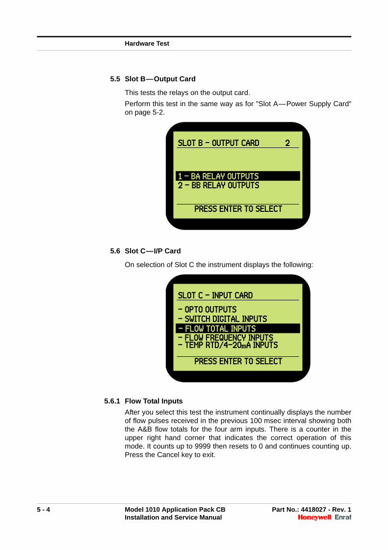
5.5 Slot B—Output Card
This tests the relays on the output card.
Perform this test in the same way as for "Slot A—Power Supply Card"on page 5-2.
5.6 Slot C—I/P Card
On selection of Slot C the instrument displays the following:
5.6.1 Flow Total Inputs
After you select this test the instrument continually displays the numberof flow pulses received in the previous 100 msec interval showing boththe A&B flow totals for the four arm inputs. There is a counter in theupper right hand corner that indicates the correct operation of thismode. It counts up to 9999 then resets to 0 and continues counting up.Press the Cancel key to exit.
SLOT B - OUTPUT CARD 2
1 - DISPLAY CONTRAST2 - BB RELAY OUTPUTS
PRESS ENTER TO SELECT
1 - BA RELAY OUTPUTS
SLOT B - OUTPUT CARD 2
1 - DISPLAY CONTRAST2 - BB RELAY OUTPUTS
PRESS ENTER TO SELECT
1 - BA RELAY OUTPUTS
SLOT C - INPUT CARD
- OPTO OUTPUTS- SWITCH DIGITAL INPUTS1 - DISPLAY CONTRAST- FLOW FREQUENCY INPUTS- TEMP RTD/4-20mA INPUTS
PRESS ENTER TO SELECT
- FLOW TOTAL INPUTS
SLOT C - INPUT CARD
- OPTO OUTPUTS- SWITCH DIGITAL INPUTS1 - DISPLAY CONTRAST- FLOW FREQUENCY INPUTS- TEMP RTD/4-20mA INPUTS
PRESS ENTER TO SELECT
- FLOW TOTAL INPUTS
Hardware Test
5 - 5 Model 1010 Application Pack CB Part No.: 4418027 - Rev. 1Installation and Service Manual
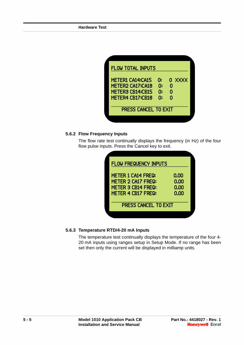
5.6.2 Flow Frequency Inputs
The flow rate test continually displays the frequency (in Hz) of the fourflow pulse inputs. Press the Cancel key to exit.
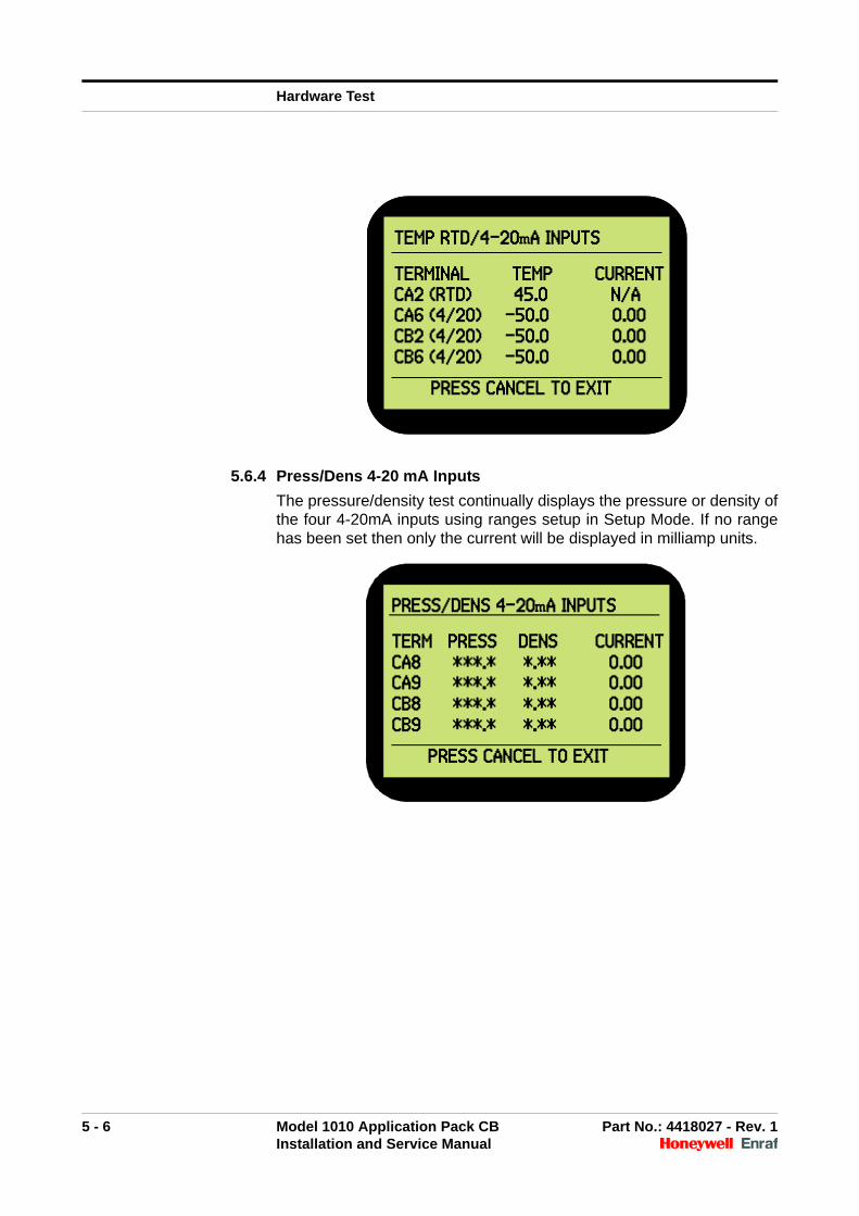
5.6.3 Temperature RTD/4-20 mA Inputs
The temperature test continually displays the temperature of the four 4-20 mA inputs using ranges setup in Setup Mode. If no range has beenset then only the current will be displayed in milliamp units.
FLOW TOTAL INPUTS
METER1 CA14:CA15 0: 0 XXXXMETER2 CA17:CA18 0: 0 METER3 CB14:CB15 0: 0 METER4 CB17:CB18 0: 0
PRESS CANCEL TO EXIT
FLOW FREQUENCY INPUTS
METER 1 CA14 FREQ: 0.00METER 2 CA17 FREQ: 0.00 METER 3 CB14 FREQ: 0.00 METER 4 CB17 FREQ: 0.00
PRESS CANCEL TO EXIT
Hardware Test
5 - 6 Model 1010 Application Pack CB Part No.: 4418027 - Rev. 1Installation and Service Manual
5.6.4 Press/Dens 4-20 mA Inputs
The pressure/density test continually displays the pressure or density ofthe four 4-20mA inputs using ranges setup in Setup Mode. If no rangehas been set then only the current will be displayed in milliamp units.
TEMP RTD/4-20mA INPUTS
TERMINAL TEMP CURRENTCA2 (RTD) 45.0 N/ACA6 (4/20) ...-50.0 0.00CB2 (4/20) ...-50.0 0.00CB6 (4/20) ...-50.0 0.00
PRESS CANCEL TO EXIT
TEMP RTD/4-20mA INPUTS
TERMINAL TEMP CURRENTCA2 (RTD) 45.0 N/ACA6 (4/20) ...-50.0 0.00CB2 (4/20) ...-50.0 0.00CB6 (4/20) ...-50.0 0.00
PRESS CANCEL TO EXIT
PRESS/DENS 4-20mA INPUTS
TERM PRESS DENS CURRENTCA8 ***.* *.** 0.00CA9 ***.* *.** 0.00CB8 ***.* *.** 0.00CB9 ***.* *.** 0.00
PRESS CANCEL TO EXIT
Hardware Test
5 - 7 Model 1010 Application Pack CB Part No.: 4418027 - Rev. 1Installation and Service Manual
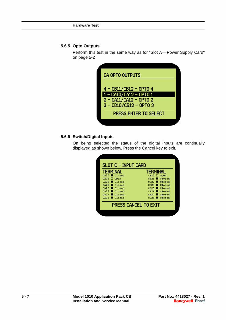
5.6.5 Opto Outputs
Perform this test in the same way as for "Slot A—Power Supply Card"on page 5-2
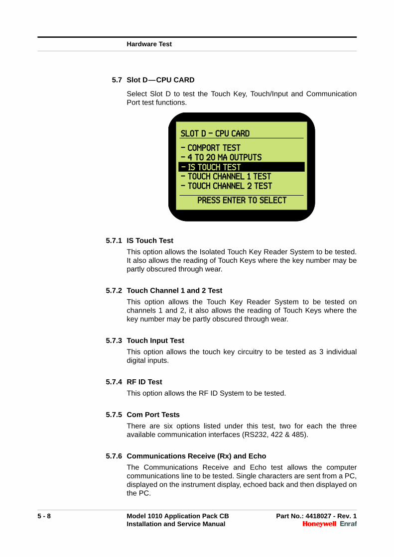
5.6.6 Switch/Digital Inputs
On being selected the status of the digital inputs are continuallydisplayed as shown below. Press the Cancel key to exit.
CA OPTO OUTPUTS
4 - CB11/CB12 - OPTO 41 - DISPLAY CONTRAST2 - CA11/CA12 - OPTO 23 - CB10/CB12 - OPTO 3
PRESS ENTER TO SELECT
1 - CA10/CA12 - OPTO 1
CA OPTO OUTPUTS
4 - CB11/CB12 - OPTO 41 - DISPLAY CONTRAST2 - CA11/CA12 - OPTO 23 - CB10/CB12 - OPTO 3
PRESS ENTER TO SELECT
1 - CA10/CA12 - OPTO 1
SLOT C - INPUT CARD
TERMINAL TERMINALCA20 Closed CB20 OpenCA21 Open CB21 ClosedCA22 Closed CB22 ClosedCA23 Closed CB23 ClosedCA25 Closed CB25 ClosedCA26 Closed CB26 ClosedCA27 Closed CB27 ClosedCA28 Closed CB28 Closed
PRESS CANCEL TO EXIT
SLOT C - INPUT CARD
TERMINAL TERMINALCA20 Closed CB20 OpenCA21 Open CB21 ClosedCA22 Closed CB22 ClosedCA23 Closed CB23 ClosedCA25 Closed CB25 ClosedCA26 Closed CB26 ClosedCA27 Closed CB27 ClosedCA28 Closed CB28 Closed
PRESS CANCEL TO EXIT
Hardware Test
5 - 8 Model 1010 Application Pack CB Part No.: 4418027 - Rev. 1Installation and Service Manual
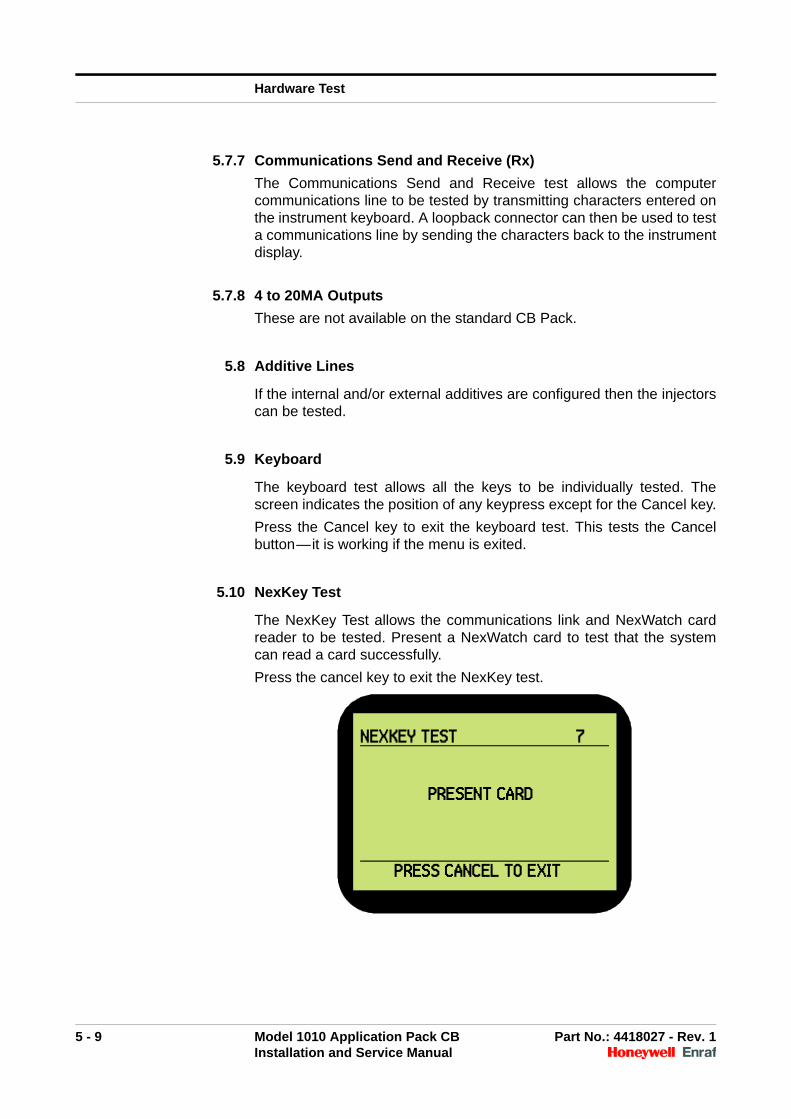
5.7 Slot D—CPU CARD
Select Slot D to test the Touch Key, Touch/Input and CommunicationPort test functions.
5.7.1 IS Touch Test
This option allows the Isolated Touch Key Reader System to be tested.It also allows the reading of Touch Keys where the key number may bepartly obscured through wear.
5.7.2 Touch Channel 1 and 2 Test
This option allows the Touch Key Reader System to be tested onchannels 1 and 2, it also allows the reading of Touch Keys where thekey number may be partly obscured through wear.
5.7.3 Touch Input Test
This option allows the touch key circuitry to be tested as 3 individualdigital inputs.
5.7.4 RF ID Test
This option allows the RF ID System to be tested.
5.7.5 Com Port Tests
There are six options listed under this test, two for each the threeavailable communication interfaces (RS232, 422 & 485).
5.7.6 Communications Receive (Rx) and Echo
The Communications Receive and Echo test allows the computercommunications line to be tested. Single characters are sent from a PC,displayed on the instrument display, echoed back and then displayed onthe PC.
SLOT D - CPU CARD
- COMPORT TEST- 4 TO 20 MA OUTPUTS1 - DISPLAY CONTRAST- TOUCH CHANNEL 1 TEST- TOUCH CHANNEL 2 TEST
PRESS ENTER TO SELECT
- IS TOUCH TEST
SLOT D - CPU CARD
- COMPORT TEST- 4 TO 20 MA OUTPUTS1 - DISPLAY CONTRAST- TOUCH CHANNEL 1 TEST- TOUCH CHANNEL 2 TEST
PRESS ENTER TO SELECT
- IS TOUCH TEST
Hardware Test
5 - 9 Model 1010 Application Pack CB Part No.: 4418027 - Rev. 1Installation and Service Manual
5.7.7 Communications Send and Receive (Rx)
The Communications Send and Receive test allows the computercommunications line to be tested by transmitting characters entered onthe instrument keyboard. A loopback connector can then be used to testa communications line by sending the characters back to the instrumentdisplay.
5.7.8 4 to 20MA Outputs
These are not available on the standard CB Pack.
5.8 Additive Lines
If the internal and/or external additives are configured then the injectorscan be tested.
5.9 Keyboard
The keyboard test allows all the keys to be individually tested. Thescreen indicates the position of any keypress except for the Cancel key.
Press the Cancel key to exit the keyboard test. This tests the Cancelbutton—it is working if the menu is exited.
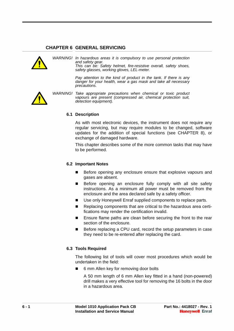
5.10 NexKey Test
The NexKey Test allows the communications link and NexWatch cardreader to be tested. Present a NexWatch card to test that the systemcan read a card successfully.
Press the cancel key to exit the NexKey test.
NEXKEY TEST 7
PRESENT CARD
PRESS CANCEL TO EXIT

Hardware Test
5 - 10 Model 1010 Application Pack CB Part No.: 4418027 - Rev. 1Installation and Service Manual
Intentionally left blank.
6 - 1 Model 1010 Application Pack CB Part No.: 4418027 - Rev. 1Installation and Service Manual
CHAPTER 6 GENERAL SERVICING
WARNING! In hazardous areas it is compulsory to use personal protectionand safety gear. This can be: Safety helmet, fire-resistive overall, safety shoes,safety glasses, working gloves, LEL-meter.
Pay attention to the kind of product in the tank. If there is anydanger for your health, wear a gas mask and take all necessaryprecautions.
WARNING! Take appropriate precautions when chemical or toxic productvapours are present (compressed air, chemical protection suit,detection equipment).
6.1 Description
As with most electronic devices, the instrument does not require anyregular servicing, but may require modules to be changed, softwareupdates for the addition of special functions (see CHAPTER 8), orexchange of damaged hardware.
This chapter describes some of the more common tasks that may haveto be performed.
6.2 Important Notes
Before opening any enclosure ensure that explosive vapours andgases are absent.
Before opening an enclosure fully comply with all site safetyinstructions. As a minimum all power must be removed from theenclosure and the area declared safe by a safety officer.
Use only Honeywell Enraf supplied components to replace parts.
Replacing components that are critical to the hazardous area certi-fications may render the certification invalid.
Ensure flame paths are clean before securing the front to the rearsection of the enclosure.
Before replacing a CPU card, record the setup parameters in casethey need to be re-entered after replacing the card.
6.3 Tools Required
The following list of tools will cover most procedures which would beundertaken in the field:
6 mm Allen key for removing door bolts
A 50 mm length of 6 mm Allen key fitted in a hand (non-powered)drill makes a very effective tool for removing the 16 bolts in the doorin a hazardous area.
General Servicing
6 - 2 Model 1010 Application Pack CB Part No.: 4418027 - Rev. 1Installation and Service Manual
WARNING! EXPLOSION HAZARD, FIRE HAZARD Avoid the use of powerdrills in hazardous areas. Using power equipment in areas wherethere may be flammable vapour may cause explosions and fire,which could cause injury or death.
3 mm flat bladed screwdriver for terminal connections
Number 2 cross recessed (Phillips head) screwdriver for removingthe cover plate and internal modules
6.4 Module Replacement
The main instrument enclosure consists of two modules:
The main electronics module, which is located in the back of theenclosure
The display module located on the rear of the door
6.4.1 Main Electronics
WARNING! Make sure that all power to the device is switched off before youopen the covers of the device. Failure to do so may cause dangerto persons or damage the equipment. All covers of the devicemust be closed before switching the power on again.
☛ To remove the main electronics module
1. Read and comply with the notes in "Important Notes" on page 6-1.
2. Remove the 16 bolts that are located on the front of the door with a6 mm Allen key. The door is supported by the removable hinges onthe left side of the enclosure.
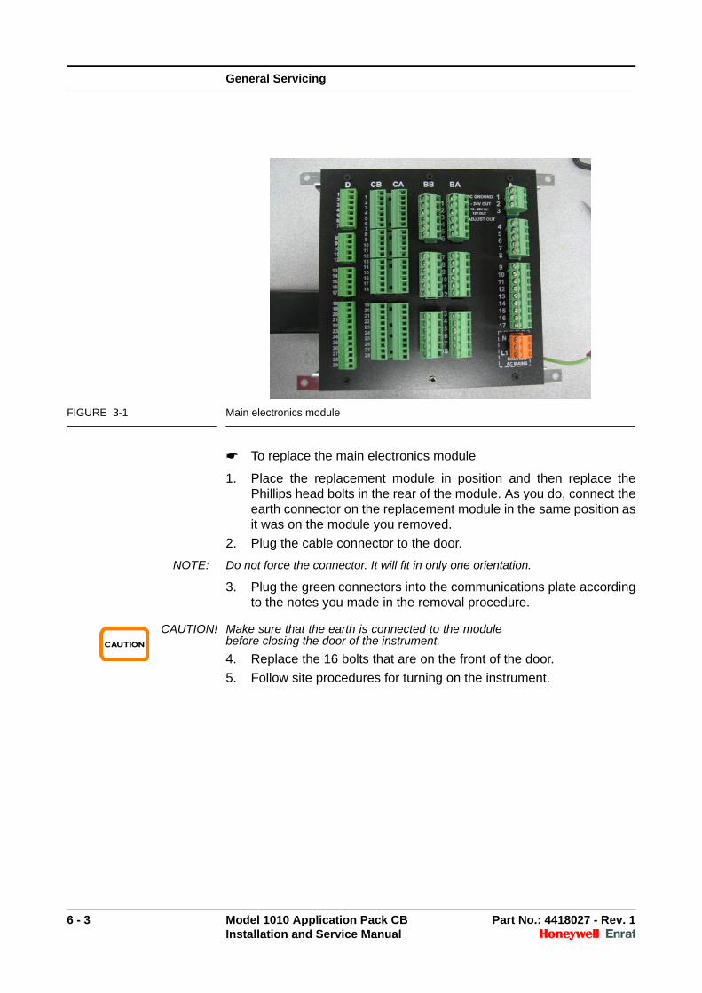
3. Note the positions of the green connectors that plug into slots A, B,C and D and then remove them from the communications plate.
4. Locate the flat black 50 mm wide cable that reaches from the leftrear of the module to a connector on the door and then unplug thecable from the door.
5. Remove the 4 mm Phillips head bolts that are located one percorner at the rear of the module using a Phillips head screwdriver.
CAUTION! The earth connection is beneath one of the cornerscrews. Note the position of the earth connector.
6. Remove the module.
General Servicing
6 - 3 Model 1010 Application Pack CB Part No.: 4418027 - Rev. 1Installation and Service Manual
FIGURE 3-1 Main electronics module
☛ To replace the main electronics module
1. Place the replacement module in position and then replace thePhillips head bolts in the rear of the module. As you do, connect theearth connector on the replacement module in the same position asit was on the module you removed.
2. Plug the cable connector to the door.
NOTE: Do not force the connector. It will fit in only one orientation.
3. Plug the green connectors into the communications plate accordingto the notes you made in the removal procedure.
CAUTION! Make sure that the earth is connected to the modulebefore closing the door of the instrument.
4. Replace the 16 bolts that are on the front of the door.
5. Follow site procedures for turning on the instrument.
General Servicing
6 - 4 Model 1010 Application Pack CB Part No.: 4418027 - Rev. 1Installation and Service Manual
6.4.2 Display Electronics
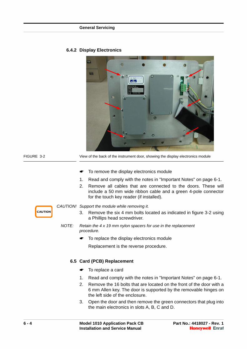
FIGURE 3-2 View of the back of the instrument door, showing the display electronics module
☛ To remove the display electronics module
1. Read and comply with the notes in "Important Notes" on page 6-1.
2. Remove all cables that are connected to the doors. These willinclude a 50 mm wide ribbon cable and a green 4-pole connectorfor the touch key reader (if installed).
CAUTION! Support the module while removing it.
3. Remove the six 4 mm bolts located as indicated in figure 3-2 usinga Phillips head screwdriver.
NOTE: Retain the 4 x 19 mm nylon spacers for use in the replacement procedure.
☛ To replace the display electronics module
Replacement is the reverse procedure.
6.5 Card (PCB) Replacement
☛ To replace a card
1. Read and comply with the notes in "Important Notes" on page 6-1.
2. Remove the 16 bolts that are located on the front of the door with a6 mm Allen key. The door is supported by the removable hinges onthe left side of the enclosure.
3. Open the door and then remove the green connectors that plug intothe main electronics in slots A, B, C and D.
General Servicing
6 - 5 Model 1010 Application Pack CB Part No.: 4418027 - Rev. 1Installation and Service Manual
4. Remove the 6 Phillips head bolts that hold the cover plate and thenremove the cover plate.
5. Identify the PCB to be replaced and remove the PCB by pulling onthe green sockets that are attached to the PCB.
6. Position the replacement PCB so that the PCB is in the guides andthen replace it by pushing on the green connectors.
7. Refit the cover plate.
8. Refit all the plugs into the correct slots A, B, C and D according tothe positions you recorded before removing them.
9. Close the door and replace the 16 bolts.
10. Follow site procedures for connecting power to the instrument andturning it on.
11. Check all setup parameters. If necessary, reprogram theinstrument.

General Servicing
6 - 6 Model 1010 Application Pack CB Part No.: 4418027 - Rev. 1Installation and Service Manual
Intentionally left blank.

7 - 1 Model 1010 Application Pack CB Part No.: 4418027 - Rev. 1Installation and Service Manual
CHAPTER 7 AUTOMATED PROVING MODE
Use Automated Proving Mode to calibrate meters.
NOTE: Automated Proving mode should only be used in conjunction with Stand Alone mode
Calibrate meters during site commissioning and periodically, based onrequirements at your site.
Before using Automated Proving Mode, the k-factors for each meterthat is being used with the instrument must be entered. For moreinformation, see the Programming Manual. The k-factor should besupplied with the meter's certificate of calibration.
To use automated proving mode, you must enter Programming Modeusing the Weights and Measures switch. For more information, see“Entering and Exiting Programming Mode” in the Programming Manual.
☛ To enter Automated Proving Mode, enter Programming Mode, thenselect SYSTEM > LOADING OPTIONS > AUTOMATED PROVING> ENABLE.
NOTE: It is often convenient to enable Test Mode when performing a meter calibration. This prevents the prompts from timing out and the instrument moving to the next screen automatically.
Once Automated Proving Mode is enabled the instrument is ready tocalibrate the meter. The following example demonstrates theAutomated Proving Mode workflow.
NOTE: The configuration of the instrument at your site may result in the screens being different from those shown in this example.
Before commencing meter calibration ensure that the calibrated provingmeter is connected to the appropriate loading arm and take all normalloading precautions.
LOADING OPTIONS 22
AUTOMATED PROVING(DISABLE ENABLE )ENABLE
LOADING OPTIONS 22
AUTOMATED PROVING(DISABLE ENABLE )
LOADING OPTIONS 22
AUTOMATED PROVING(DISABLE ENABLE )ENABLE
Automated Proving Mode
7 - 2 Model 1010 Application Pack CB Part No.: 4418027 - Rev. 1Installation and Service Manual
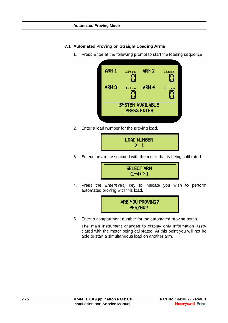
7.1 Automated Proving on Straight Loading Arms
1. Press Enter at the following prompt to start the loading sequence.
2. Enter a load number for the proving load.
3. Select the arm associated with the meter that is being calibrated.
4. Press the Enter/(Yes) key to indicate you wish to performautomated proving with this load.
5. Enter a compartment number for the automated proving batch.
The main instrument changes to display only information asso-ciated with the meter being calibrated. At this point you will not beable to start a simultaneous load on another arm.
ARM 1 litre ARM 2 litre
ARM 3 litre ARM 4 litre
SYSTEM AVAILABLE PRESS ENTER
ARM 1 litre ARM 2 litre
ARM 3 litre ARM 4 litre
SYSTEM AVAILABLE PRESS ENTER
LOAD NUMBER > 1
LOAD NUMBER > 1
SELECT ARM (1-4) > 1
SELECT ARM (1-4) > 1
ARE YOU PROVING?YES/NO?
ARE YOU PROVING?YES/NO?
Automated Proving Mode
7 - 3 Model 1010 Application Pack CB Part No.: 4418027 - Rev. 1Installation and Service Manual
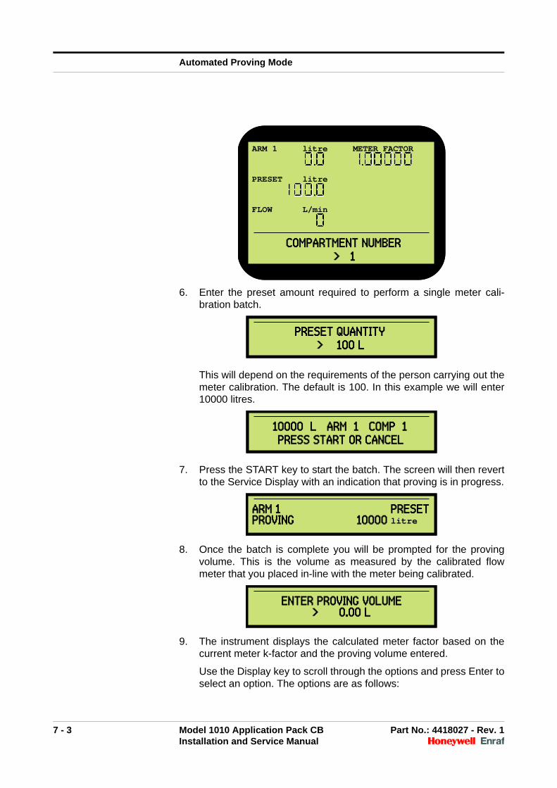
6. Enter the preset amount required to perform a single meter cali-bration batch.
This will depend on the requirements of the person carrying out themeter calibration. The default is 100. In this example we will enter10000 litres.
7. Press the START key to start the batch. The screen will then revertto the Service Display with an indication that proving is in progress.
8. Once the batch is complete you will be prompted for the provingvolume. This is the volume as measured by the calibrated flowmeter that you placed in-line with the meter being calibrated.
9. The instrument displays the calculated meter factor based on thecurrent meter k-factor and the proving volume entered.
Use the Display key to scroll through the options and press Enter toselect an option. The options are as follows:
ARM 1 litre METER FACTOR
PRESET litre
FLOW L/min
COMPARTMENT NUMBER> 1
ARM 1 litre METER FACTOR
PRESET litre
FLOW L/min
COMPARTMENT NUMBER> 1
PRESET QUANTITY > 100 L
PRESET QUANTITY > 100 L
10000 L ARM 1 COMP 1 PRESS START OR CANCEL
10000 L ARM 1 COMP 1 PRESS START OR CANCEL
ARM 1 PRESETPROVING 10000 litre ARM 1 PRESETPROVING 10000 litre
ENTER PROVING VOLUME> 0.00 L
ENTER PROVING VOLUME> 0.00 L
Automated Proving Mode
7 - 4 Model 1010 Application Pack CB Part No.: 4418027 - Rev. 1Installation and Service Manual
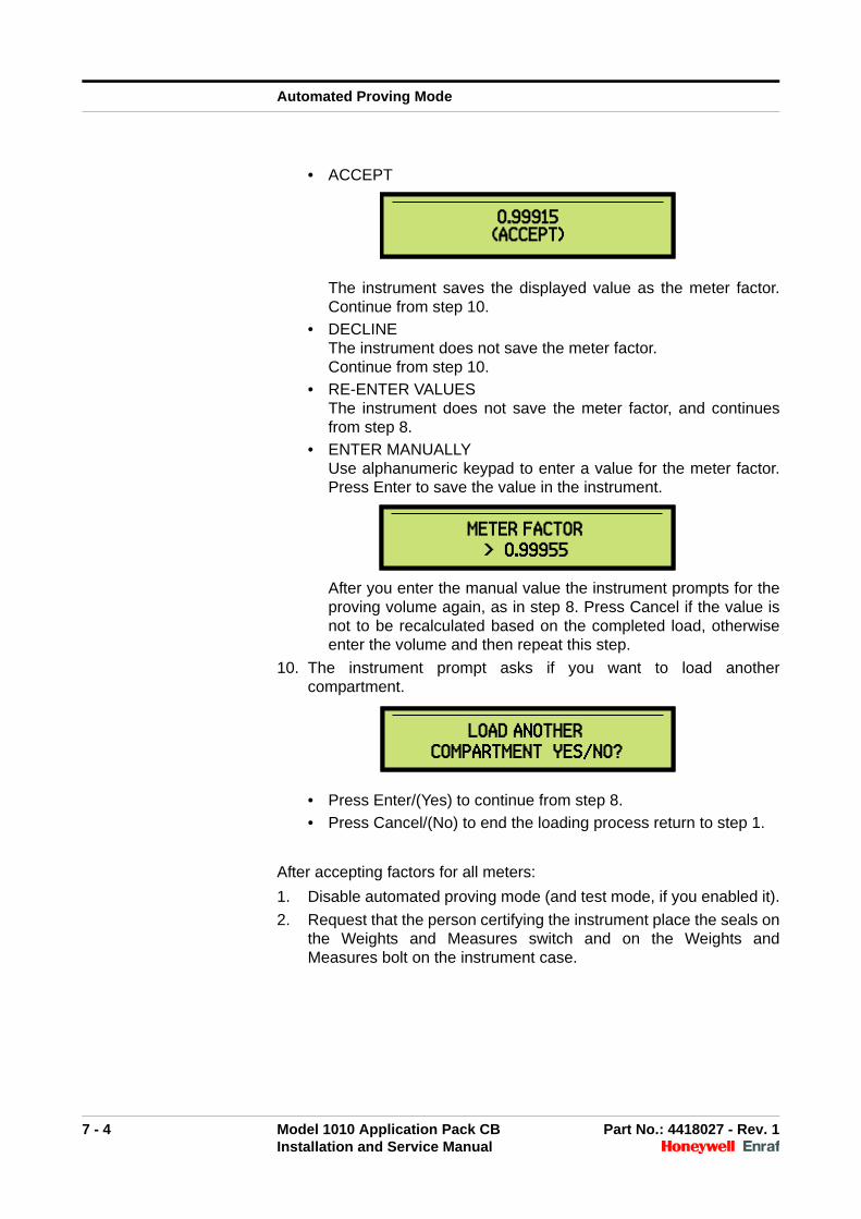
• ACCEPT
The instrument saves the displayed value as the meter factor.Continue from step 10.
• DECLINEThe instrument does not save the meter factor. Continue from step 10.
• RE-ENTER VALUESThe instrument does not save the meter factor, and continuesfrom step 8.
• ENTER MANUALLYUse alphanumeric keypad to enter a value for the meter factor.Press Enter to save the value in the instrument.
After you enter the manual value the instrument prompts for theproving volume again, as in step 8. Press Cancel if the value isnot to be recalculated based on the completed load, otherwiseenter the volume and then repeat this step.
10. The instrument prompt asks if you want to load anothercompartment.
• Press Enter/(Yes) to continue from step 8.
• Press Cancel/(No) to end the loading process return to step 1.
After accepting factors for all meters:
1. Disable automated proving mode (and test mode, if you enabled it).
2. Request that the person certifying the instrument place the seals onthe Weights and Measures switch and on the Weights andMeasures bolt on the instrument case.
0.99915(ACCEPT)0.99915
(ACCEPT)
METER FACTOR > 0.99955
METER FACTOR > 0.99955
LOAD ANOTHER COMPARTMENT YES/NO?
LOAD ANOTHER COMPARTMENT YES/NO?
Automated Proving Mode
7 - 5 Model 1010 Application Pack CB Part No.: 4418027 - Rev. 1Installation and Service Manual
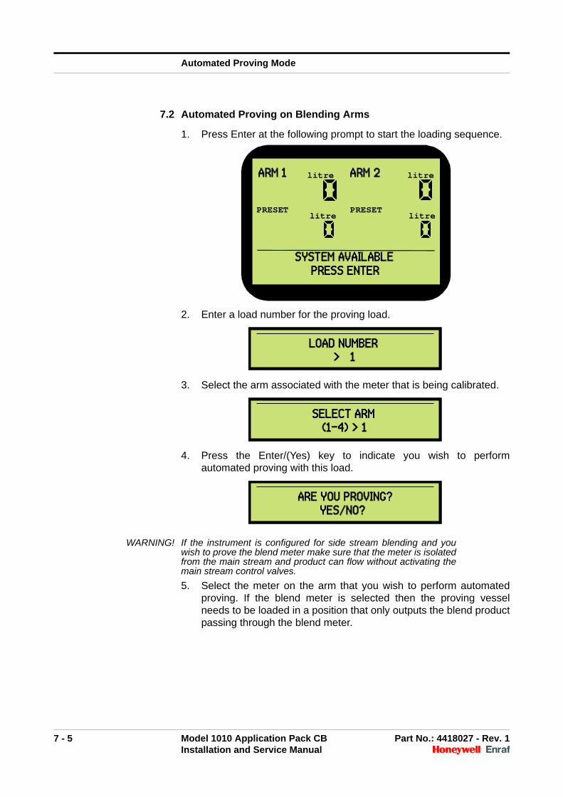
7.2 Automated Proving on Blending Arms
1. Press Enter at the following prompt to start the loading sequence.
2. Enter a load number for the proving load.
3. Select the arm associated with the meter that is being calibrated.
4. Press the Enter/(Yes) key to indicate you wish to performautomated proving with this load.
WARNING! If the instrument is configured for side stream blending and youwish to prove the blend meter make sure that the meter is isolatedfrom the main stream and product can flow without activating themain stream control valves.
5. Select the meter on the arm that you wish to perform automatedproving. If the blend meter is selected then the proving vesselneeds to be loaded in a position that only outputs the blend productpassing through the blend meter.
ARM 1 litre ARM 2 litre
PRESETlitre
PRESETlitre
SYSTEM AVAILABLE PRESS ENTER
LOAD NUMBER > 1
LOAD NUMBER > 1
SELECT ARM (1-4) > 1
SELECT ARM (1-4) > 1
ARE YOU PROVING?YES/NO?
ARE YOU PROVING?YES/NO?
Automated Proving Mode
7 - 6 Model 1010 Application Pack CB Part No.: 4418027 - Rev. 1Installation and Service Manual
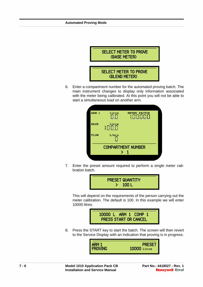
6. Enter a compartment number for the automated proving batch. Themain instrument changes to display only information associatedwith the meter being calibrated. At this point you will not be able tostart a simultaneous load on another arm.
7. Enter the preset amount required to perform a single meter cali-bration batch.
This will depend on the requirements of the person carrying out themeter calibration. The default is 100. In this example we will enter10000 litres.
8. Press the START key to start the batch. The screen will then revertto the Service Display with an indication that proving is in progress.
SELECT METER TO PROVE(BASE METER)
SELECT METER TO PROVE(BLEND METER)
ARM 1 litre METER FACTOR
BASE litre
FLOW L/min
COMPARTMENT NUMBER> 1
PRESET QUANTITY > 100 L
PRESET QUANTITY > 100 L
10000 L ARM 1 COMP 1 PRESS START OR CANCEL
10000 L ARM 1 COMP 1 PRESS START OR CANCEL
ARM 1 PRESETPROVING 10000 litre ARM 1 PRESETPROVING 10000 litre
Automated Proving Mode
7 - 7 Model 1010 Application Pack CB Part No.: 4418027 - Rev. 1Installation and Service Manual
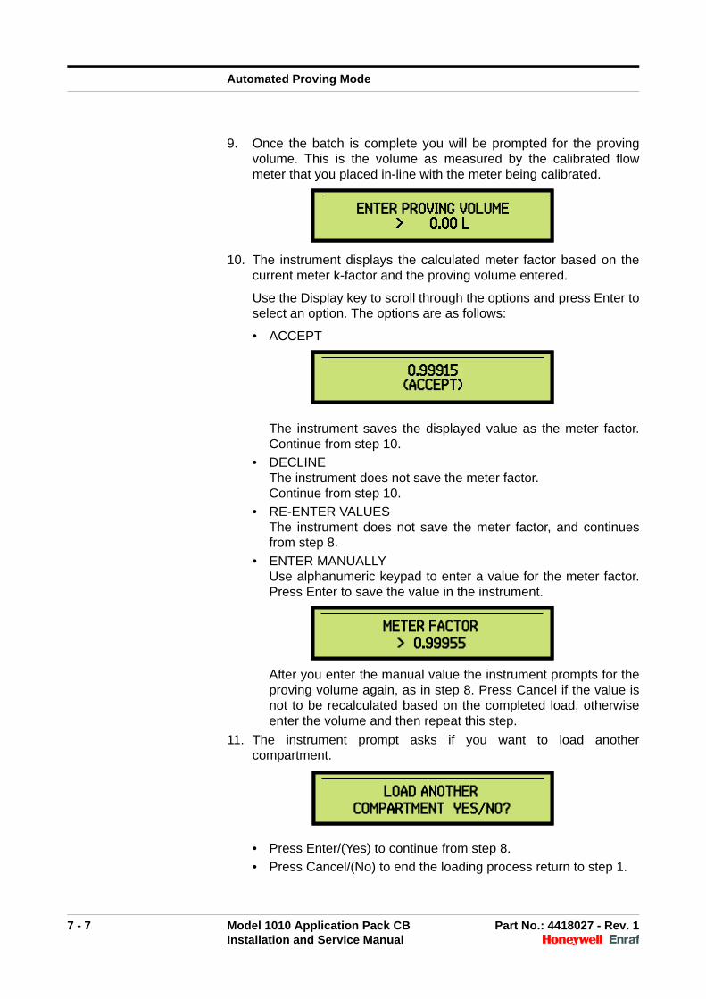
9. Once the batch is complete you will be prompted for the provingvolume. This is the volume as measured by the calibrated flowmeter that you placed in-line with the meter being calibrated.
10. The instrument displays the calculated meter factor based on thecurrent meter k-factor and the proving volume entered.
Use the Display key to scroll through the options and press Enter toselect an option. The options are as follows:
• ACCEPT
The instrument saves the displayed value as the meter factor.Continue from step 10.
• DECLINEThe instrument does not save the meter factor. Continue from step 10.
• RE-ENTER VALUESThe instrument does not save the meter factor, and continuesfrom step 8.
• ENTER MANUALLYUse alphanumeric keypad to enter a value for the meter factor.Press Enter to save the value in the instrument.
After you enter the manual value the instrument prompts for theproving volume again, as in step 8. Press Cancel if the value isnot to be recalculated based on the completed load, otherwiseenter the volume and then repeat this step.
11. The instrument prompt asks if you want to load anothercompartment.
• Press Enter/(Yes) to continue from step 8.
• Press Cancel/(No) to end the loading process return to step 1.
ENTER PROVING VOLUME> 0.00 L
ENTER PROVING VOLUME> 0.00 L
0.99915(ACCEPT)0.99915
(ACCEPT)
METER FACTOR > 0.99955
METER FACTOR > 0.99955
LOAD ANOTHER COMPARTMENT YES/NO?
LOAD ANOTHER COMPARTMENT YES/NO?
Automated Proving Mode
7 - 8 Model 1010 Application Pack CB Part No.: 4418027 - Rev. 1Installation and Service Manual
After accepting factors for all meters:
1. Disable automated proving mode (and test mode, if you enabled it).
2. Request that the person certifying the instrument place the seals onthe Weights and Measures switch and on the Weights andMeasures bolt on the instrument case.
7.3 Internal Additive Meter Proving or Calibration
The calibration or meter proving of the internal additive injector consistsof dispensing additive chemical through the injector in as close tooperating conditions as possible. The volume measured by the injectoris then divided by the volume observed by the operator. A correctionfactor or meter factor results from this math. The meter factor is storedinto configuration memory and is multiplied by the original k-factor toobtain a working k-factor that is used throughout the injection operation.The instrument performs all these calculations so the procedure is veryeasy to perform.
To accurately calibrate an additive injector, the procedure requires morethan one test cycle. A test run should include 5 to 10 injections so amore accurate average may be obtained.
The test procedure can only be carried out when the instrument is idle.The test injections will be allowed via the 8 key but the calibration will beallowed only through W&M switch.
1. Close the outlet needle valve.
2. Connect the dry-break fitting to the test port.
3. Enter the test menu (password 800) and select “ADDITIVE LINES”.
4. The next menu allows for selection between internal and externaladditive injectors. Select “INTERNAL ADDITIVES”.
5. The instrument will then prompt for the internal additive injector youwish to prove - select the appropriate injector.
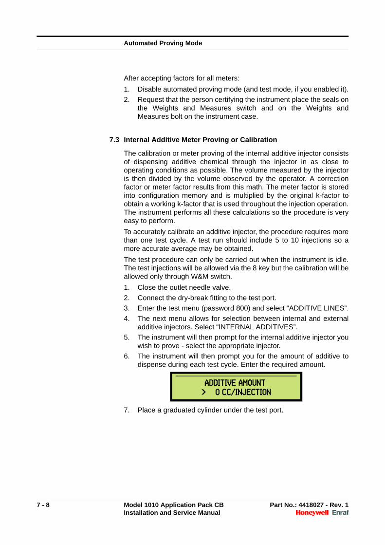
6. The instrument will then prompt you for the amount of additive todispense during each test cycle. Enter the required amount.
7. Place a graduated cylinder under the test port.
ADDITIVE AMOUNT > 0 CC/INJECTION
Automated Proving Mode
7 - 9 Model 1010 Application Pack CB Part No.: 4418027 - Rev. 1Installation and Service Manual
For each cycle:
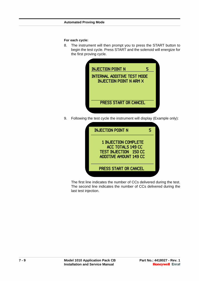
8. The instrument will then prompt you to press the START button tobegin the test cycle. Press START and the solenoid will energize forthe first proving cycle.
9. Following the test cycle the instrument will display (Example only):
The first line indicates the number of CCs delivered during the test.The second line indicates the number of CCs delivered during thelast test injection.
INJECTION POINT N 5
INTERNAL ADDITIVE TEST MODEINJECTION POINT N ARM X
PRESS START OR CANCEL
INJECTION POINT N 5
INTERNAL ADDITIVE TEST MODEINJECTION POINT N ARM X
PRESS START OR CANCEL
INJECTION POINT N 5
1 INJECTION COMPLETEACC TOTALS 149 CC
TEST INJECTION 150 CCADDITIVE AMOUNT 149 CC
PRESS START OR CANCEL
INJECTION POINT N 5
1 INJECTION COMPLETEACC TOTALS 149 CC
TEST INJECTION 150 CCADDITIVE AMOUNT 149 CC
PRESS START OR CANCEL
Automated Proving Mode
7 - 10 Model 1010 Application Pack CB Part No.: 4418027 - Rev. 1Installation and Service Manual
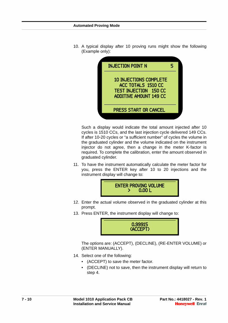
10. A typical display after 10 proving runs might show the following(Example only):
Such a display would indicate the total amount injected after 10cycles is 1510 CCs, and the last injection cycle delivered 149 CCs.If after 10-20 cycles or “a sufficient number” of cycles the volume inthe graduated cylinder and the volume indicated on the instrumentinjector do not agree, then a change in the meter K-factor isrequired. To complete the calibration, enter the amount observed ingraduated cylinder.
11. To have the instrument automatically calculate the meter factor foryou, press the ENTER key after 10 to 20 injections and theinstrument display will change to:
12. Enter the actual volume observed in the graduated cylinder at thisprompt.
13. Press ENTER, the instrument display will change to:
The options are: (ACCEPT), (DECLINE), (RE-ENTER VOLUME) or(ENTER MANUALLY).
14. Select one of the following:
• (ACCEPT) to save the meter factor.
• (DECLINE) not to save, then the instrument display will return tostep 4.
INJECTION POINT N 5
10 INJECTIONS COMPLETEACC TOTALS 1510 CC
TEST INJECTION 150 CCADDITIVE AMOUNT 149 CC
PRESS START OR CANCEL
INJECTION POINT N 5
10 INJECTIONS COMPLETEACC TOTALS 1510 CC
TEST INJECTION 150 CCADDITIVE AMOUNT 149 CC
PRESS START OR CANCEL
ENTER PROVING VOLUME> 0.00 L
ENTER PROVING VOLUME> 0.00 L
0.99915(ACCEPT)0.99915
(ACCEPT)
Automated Proving Mode
7 - 11 Model 1010 Application Pack CB Part No.: 4418027 - Rev. 1Installation and Service Manual
• (RE-ENTER VOLUME) not to save, then the instrument displaywill return to step 11, allowing the operator to re-enter theproving volume.
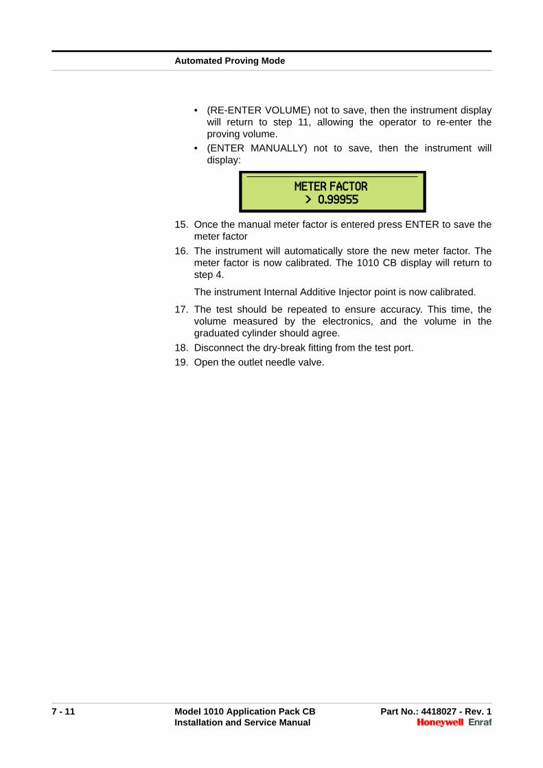
• (ENTER MANUALLY) not to save, then the instrument willdisplay:
15. Once the manual meter factor is entered press ENTER to save themeter factor
16. The instrument will automatically store the new meter factor. Themeter factor is now calibrated. The 1010 CB display will return tostep 4.
The instrument Internal Additive Injector point is now calibrated.
17. The test should be repeated to ensure accuracy. This time, thevolume measured by the electronics, and the volume in thegraduated cylinder should agree.
18. Disconnect the dry-break fitting from the test port.
19. Open the outlet needle valve.
METER FACTOR > 0.99955
METER FACTOR > 0.99955

Automated Proving Mode
7 - 12 Model 1010 Application Pack CB Part No.: 4418027 - Rev. 1Installation and Service Manual
Intentionally left blank.

8 - 1 Model 1010 Application Pack CB Part No.: 4418027 - Rev. 1Installation and Service Manual
CHAPTER 8 FIRMWARE UPDATE
8.1 Description
8.2 Tools Required
The following tools are necessary to update the firmware:
Honeywell Enraf 1010 instrument with
• SP10CPU-C00-I3 card installed
• CB application pack loaded and working
Personnel computer with
• Serial communications port (interface (RS232/RS422/RS485)will depend on how the target instrument is configured)
• Windows 7, Vista, or XP
Application binary file (version V02_000 or greater)
1010_Flash_programmer_V3.exe (1010 programming utility)
8.3 Instrument Configuration
Before updating the firmware, configure the instrument as follows:
Enable Master Authorisation.
Enter a Master Authorisation ID. For more information, see “EditMaster IDs” in the Programming Manual.
From the main menu, select SYSTEM > COMMUNICATION >PORT 1 and then enter the instrument address. For more infor-mation, see “Communications” in the Programming Manual.
8.4 Updating the Firmware
To update the firmware, perform the following procedures in the ordergiven:
1. "Run the programming utility" on page 8-1.
2. "Activate the 1010 flash boot loader program" on page 8-2.
3. "Download the firmware" on page 8-5.
If you encounter problems during these procedures, see "TroubleShooting Firmware Updates" on page 8-7.
☛ Run the programming utility
1. Save the application binary file and the programming utility to atemporary folder on the host computer (for example c:\1010Upgrade).
2. Run the programming utility from the temporary folder.
Firmware Update
8 - 2 Model 1010 Application Pack CB Part No.: 4418027 - Rev. 1Installation and Service Manual
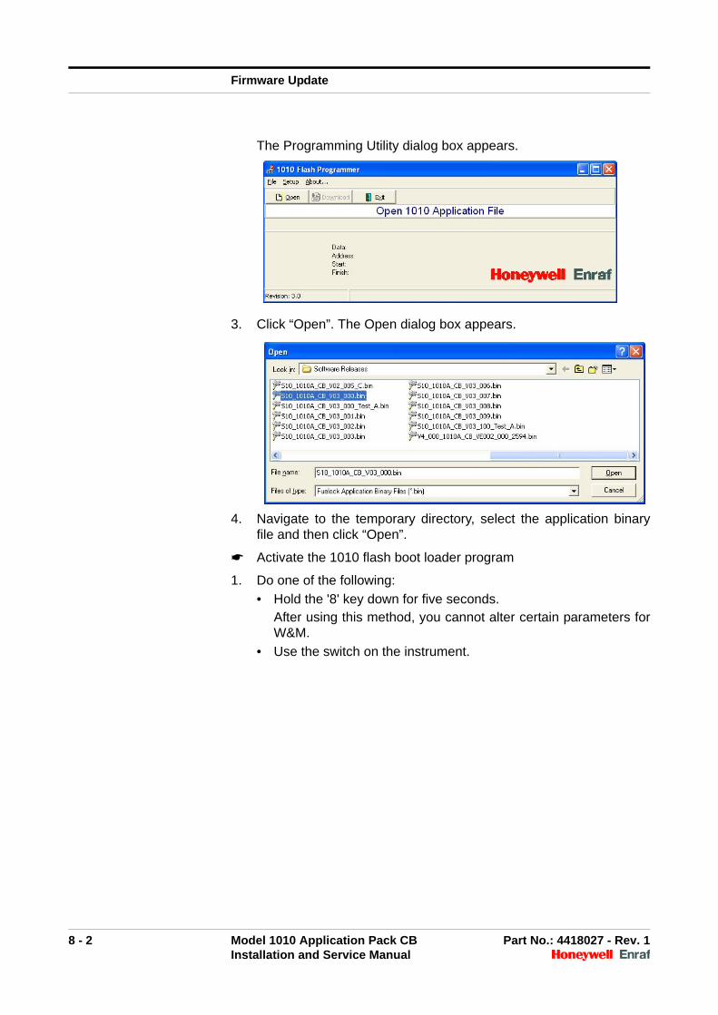
The Programming Utility dialog box appears.
3. Click “Open”. The Open dialog box appears.
4. Navigate to the temporary directory, select the application binaryfile and then click “Open”.
☛ Activate the 1010 flash boot loader program
1. Do one of the following:
• Hold the '8' key down for five seconds.After using this method, you cannot alter certain parameters forW&M.
• Use the switch on the instrument.
Firmware Update
8 - 3 Model 1010 Application Pack CB Part No.: 4418027 - Rev. 1Installation and Service Manual
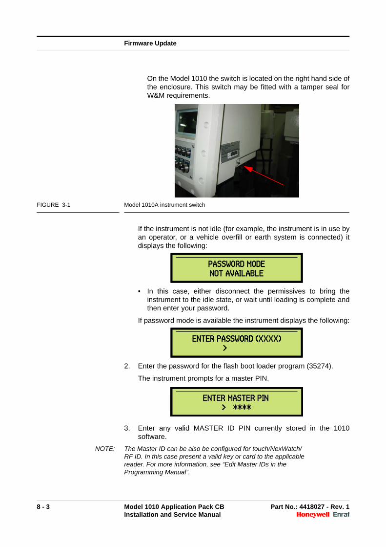
On the Model 1010 the switch is located on the right hand side ofthe enclosure. This switch may be fitted with a tamper seal forW&M requirements.
FIGURE 3-1 Model 1010A instrument switch
If the instrument is not idle (for example, the instrument is in use byan operator, or a vehicle overfill or earth system is connected) itdisplays the following:
• In this case, either disconnect the permissives to bring theinstrument to the idle state, or wait until loading is complete andthen enter your password.
If password mode is available the instrument displays the following:
2. Enter the password for the flash boot loader program (35274).
The instrument prompts for a master PIN.
3. Enter any valid MASTER ID PIN currently stored in the 1010software.
NOTE: The Master ID can be also be configured for touch/NexWatch/RF ID. In this case present a valid key or card to the applicable reader. For more information, see “Edit Master IDs in the Programming Manual”.
PASSWORD MODENOT AVAILABLEPASSWORD MODENOT AVAILABLE
ENTER PASSWORD (XXXX)>
ENTER PASSWORD (XXXX)>
Firmware Update
8 - 4 Model 1010 Application Pack CB Part No.: 4418027 - Rev. 1Installation and Service Manual
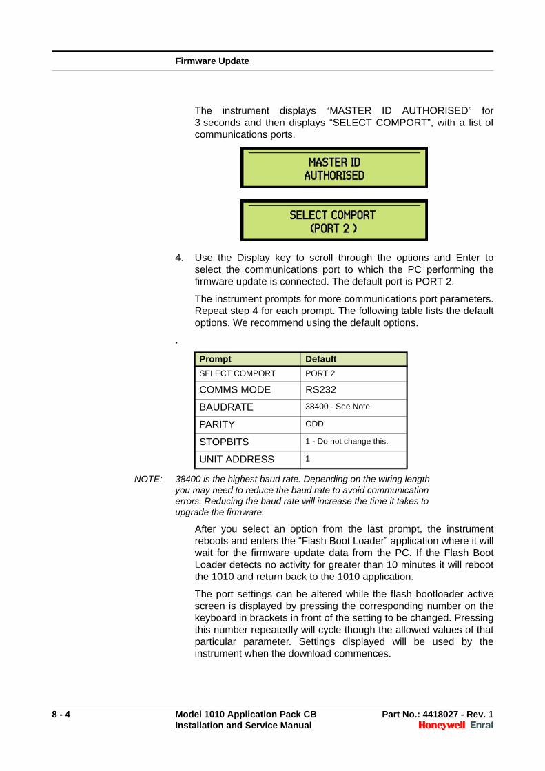
The instrument displays “MASTER ID AUTHORISED” for3 seconds and then displays “SELECT COMPORT”, with a list ofcommunications ports.
4. Use the Display key to scroll through the options and Enter toselect the communications port to which the PC performing thefirmware update is connected. The default port is PORT 2.
The instrument prompts for more communications port parameters.Repeat step 4 for each prompt. The following table lists the defaultoptions. We recommend using the default options.
.
NOTE: 38400 is the highest baud rate. Depending on the wiring length you may need to reduce the baud rate to avoid communication errors. Reducing the baud rate will increase the time it takes to upgrade the firmware.
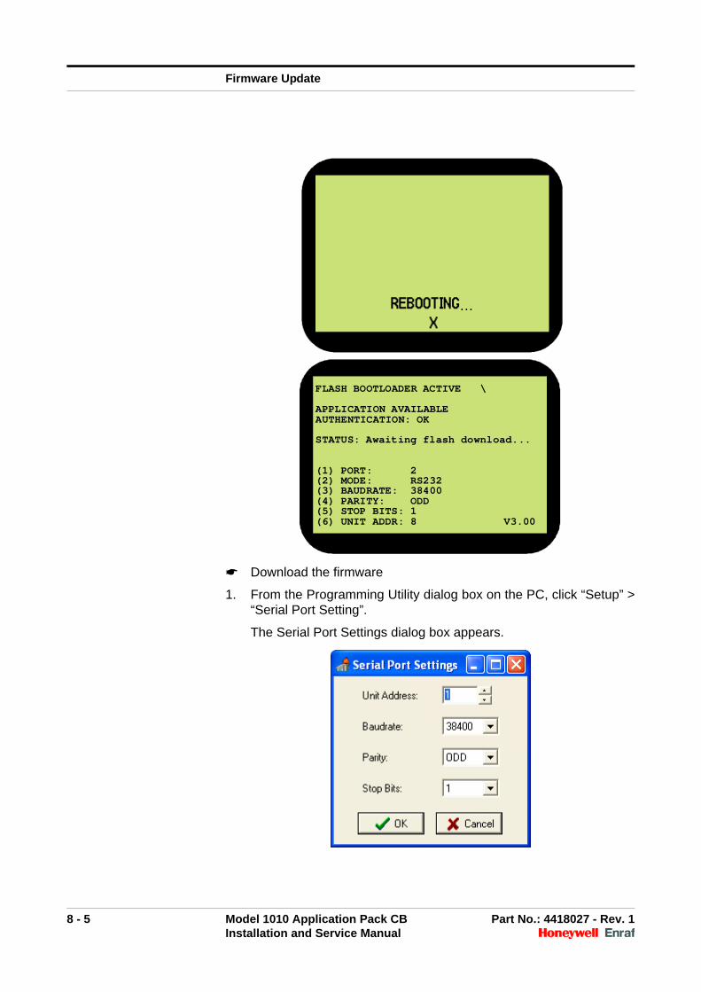
After you select an option from the last prompt, the instrumentreboots and enters the “Flash Boot Loader” application where it willwait for the firmware update data from the PC. If the Flash BootLoader detects no activity for greater than 10 minutes it will rebootthe 1010 and return back to the 1010 application.
The port settings can be altered while the flash bootloader activescreen is displayed by pressing the corresponding number on thekeyboard in brackets in front of the setting to be changed. Pressingthis number repeatedly will cycle though the allowed values of thatparticular parameter. Settings displayed will be used by theinstrument when the download commences.
Prompt Default
SELECT COMPORT PORT 2
COMMS MODE RS232
BAUDRATE 38400 - See Note
PARITY ODD
STOPBITS 1 - Do not change this.
UNIT ADDRESS 1
Firmware Update
8 - 5 Model 1010 Application Pack CB Part No.: 4418027 - Rev. 1Installation and Service Manual
☛ Download the firmware
1. From the Programming Utility dialog box on the PC, click “Setup” >“Serial Port Setting”.
The Serial Port Settings dialog box appears.
REBOOTING…X
FLASH BOOTLOADER ACTIVE \
APPLICATION AVAILABLEAUTHENTICATION: OK
STATUS: Awaiting flash download...
(1) PORT: 2(2) MODE: RS232(3) BAUDRATE: 38400(4) PARITY: ODD(5) STOP BITS: 1(6) UNIT ADDR: 8 V3.00
Firmware Update
8 - 6 Model 1010 Application Pack CB Part No.: 4418027 - Rev. 1Installation and Service Manual
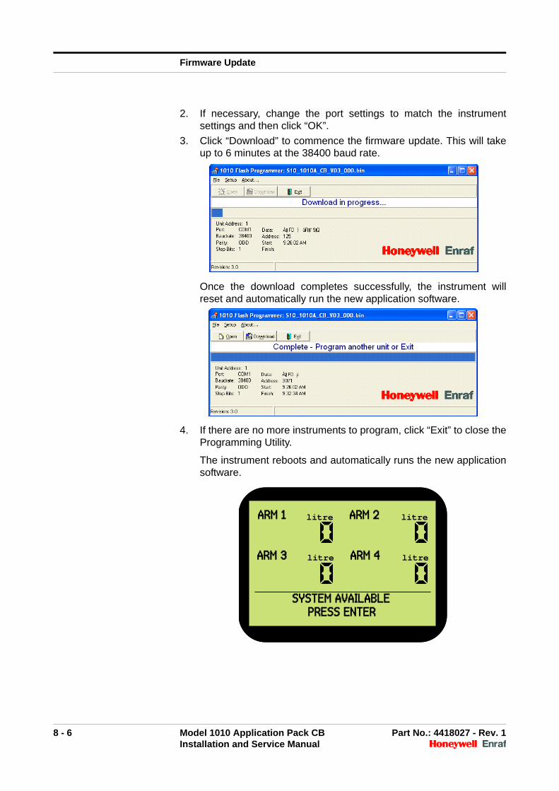
2. If necessary, change the port settings to match the instrumentsettings and then click “OK”.
3. Click “Download” to commence the firmware update. This will takeup to 6 minutes at the 38400 baud rate.
Once the download completes successfully, the instrument willreset and automatically run the new application software.
4. If there are no more instruments to program, click “Exit” to close theProgramming Utility.
The instrument reboots and automatically runs the new applicationsoftware.
ARM 1 litre ARM 2 litre
ARM 3 litre ARM 4 litre
SYSTEM AVAILABLE PRESS ENTER
ARM 1 litre ARM 2 litre
ARM 3 litre ARM 4 litre
SYSTEM AVAILABLE PRESS ENTER
Firmware Update
8 - 7 Model 1010 Application Pack CB Part No.: 4418027 - Rev. 1Installation and Service Manual
8.5 Trouble Shooting Firmware Updates
8.5.1 Time-outs
Programming Utility times out during the update.
Possible Cause Communication errors.
Solution Reduce the baud rate at both the instrument and the computer and tryagain.
8.5.2 Comms Test Failure
Programming Utility shows “Comms Test Failed - no response”
Possible Cause Another program may have exclusive access to the serialcommunications port on your computer.
Solution Close the other program.
Possible Cause Wiring problem resulting in no serial communications between theinstrument and the computer.
Solution Check the wiring connections.
Possible Cause The wiring is too long.
Solution Reduce the baud rate and try again.
Possible Cause Instrument address on the 1010 port used does not match that set in theprogramming utility.
Solution Begin from "Activate the 1010 flash boot loader program" on page 8-2,making sure to set the instrument address to 1 at step 4.
8.5.3 Incorrect Checksum
The programming utility displays the message “Incorrect checksum infile, file was not downloaded”.
Possible Cause The binary file is corrupt.
Solution Obtain a new binary file.
Firmware Update
8 - 8 Model 1010 Application Pack CB Part No.: 4418027 - Rev. 1Installation and Service Manual
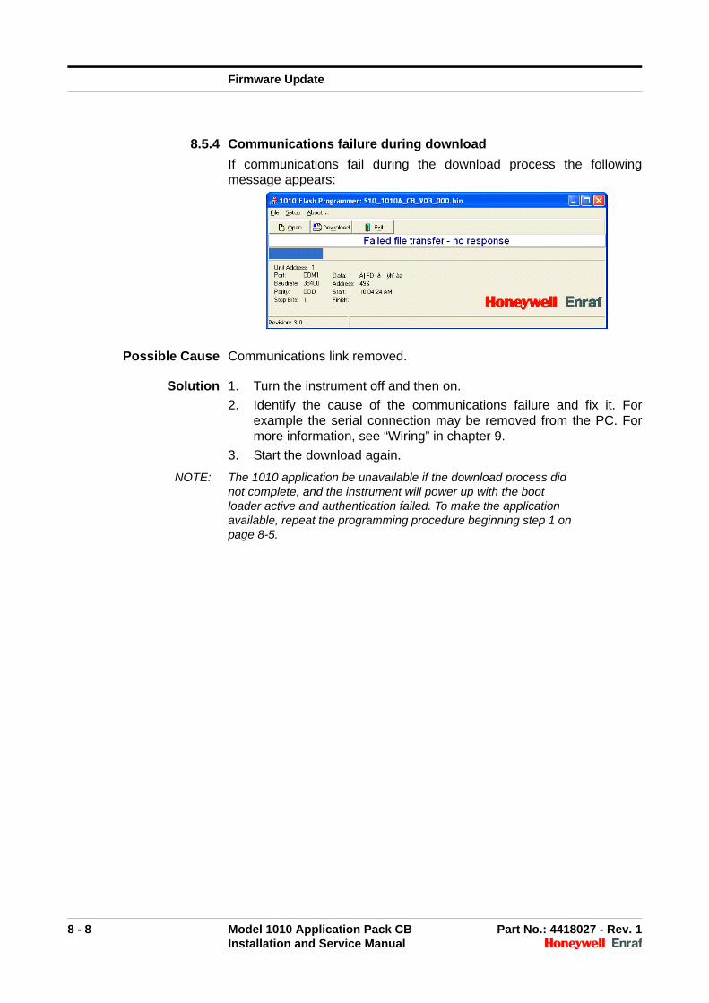
8.5.4 Communications failure during download
If communications fail during the download process the followingmessage appears:
Possible Cause Communications link removed.
Solution 1. Turn the instrument off and then on.
2. Identify the cause of the communications failure and fix it. Forexample the serial connection may be removed from the PC. Formore information, see “Wiring” in chapter 9.
3. Start the download again.
NOTE: The 1010 application be unavailable if the download process did not complete, and the instrument will power up with the boot loader active and authentication failed. To make the application available, repeat the programming procedure beginning step 1 on page 8-5.

9 - 1 Model 1010 Application Pack CB Part No.: 4418027 - Rev. 1Installation and Service Manual
CHAPTER 9 TROUBLE SHOOTING
9.1 Description
In the event of system failure, the ability to quickly identify the source ofthe problem and take corrective action to minimize downtime will helpmaintain a high level of productivity.
If the instrument encounters a problem, it will attempt to identify theproblem and display a message indicating the source.
Due to the limited test equipment which may be taken into a hazardousarea, the instrument internal Hardware Test program (see CHAPTER 5"Hardware Test") can be an asset in isolating problems.
9.2 Wiring
Wiring can be a common source of problems in any installation, causingboth intermittent and total failures, such as:
Broken wiring due to physical damage
Ingress of water at junction boxes, causing corrosion and shortcircuits
Intermittent failures due to incorrect cable type, particularly in highspeed communications lines
Screens not terminated correctly, causing earth loops
9.3 Power Supplies
A number of devices connected to the instrument may require power,such as temperature probes, flow meters and signal isolators/amplifiers.Check for other devices connected to the same power supply as theymay be the cause of the problems.
It is recommended not to power the NexWatch card reader off theinstrument power supply. The instrument 12VDC be used only if noother devices are powered off this output, otherwise operation of thecard reader can not be guaranteed. An independent power supply isrecommended for the NexWatch card reader. See the CardDescriptions and Wiring Manual for details.
Always ensure that the maximum current draw of the devices attachedto the instrument power supply outputs does not exceed the maximumcurrent rating:
250 mA max for the 12 Vdc output
100 mA max for the adjustable output
For more information, see “Power Supply Card—S800PS4-6” in theCard Descriptions and Wiring Manual.
Trouble Shooting
9 - 2 Model 1010 Application Pack CB Part No.: 4418027 - Rev. 1Installation and Service Manual
9.4 Emergency Stop
If the instrument displays the message “Clear Emergency Stop” orcustomized message equivalent:
Check the status of the Master Emergency Stop switch
Use the Input Test in the Hardware Test Program (see CHAPTER5) to monitor the status of the input
To operate, the instrument must “see” a closed contact.
9.5 Pulser Error
A Pulser Error, known in the system as a flowmeter error, occurs whenthe instrument is set up for dual input (2 signal outputs from theflowmeter) but the instrument only detects a single input. This error maybe due to:
Pulser failure
A wiring problem
9.6 No Flow Timeout Error
A No Flow Timeout Error occurs when the instrument does not receivepulses from the flowmeter for a time exceeding the SIGNAL TIMEOUTvalue, as programmed in the Setup Mode.
This may be due to a number of factors, such as:
Signal timeout value too small to allow flow to start
A blocked pipe
A manual valve closed
The flowmeter is damaged
The control valve not working correctly
The pump is not working
Wiring to pump is damaged
Wiring to the isolation valves is damaged
9.7 Scully Overfill
If the instrument displays the message “Reconnect or Clear Overfill/Ground” or customised equivalent then the overfill system has beenactivated. If the problem continues to occur check the:
Condition of the truck connection for corrosion, broken contacts,etc.
Overfill/Ground system relay contact to the instrument. Use theinput test in the Hardware Test Program (see CHAPTER 5) tomonitor the status of the input.
Trouble Shooting
9 - 3 Model 1010 Application Pack CB Part No.: 4418027 - Rev. 1Installation and Service Manual
9.8 Internal Additives
A number of errors can be reported when loading is terminated due tointernal additive problems. If the continue batch on alarm feature isenabled for these alarms then the load can be forced to continue withthe error present. This should only be used if the blend accuracy is notcritical to the final product. In this case the error is still flagged in the ALSLIP response and error codes are stored in the batch record.
The following errors can be reported:
Error 70 - Internal Additive No Flow
If this error occurs then a check of the wiring to the monoblock solenoidinput and flowmeter output is required along with the internal additivepump demand output of the instrument, this may active a pump directlyor be used as a logic input to control an isolation valve. Also check forblockage in the additive system at filter/screen locations.
Error 71 - Internal Additive Leakage
If this error occurs ensure the solenoid on the monoblock is not stuckopen or partially blocked with foreign material causing the injector tostay open. Filters/Screens should be used prior to the monoblock toensure foreign material is kept out of the additive system.
Error 72 - Internal Additive High
If error occurs check the additive settings on the instrument such ashigh flow rate, pacing volume, additive flush volume, preset quantityand recipe quantities. There may also be a solenoid fault where thesolenoid is leaking during the load or not closing fast enough.
Error 73 - Internal Additive Low
If the High Flowrate is too large for the set pacing volume or the amountof additive per injection is too large based on pacing volume to allowenough time for additive to be injected before the next injection is due,the inject would be open for the entire duration of the load. The ideallytuned system is such that the injector solenoid is open 50% of the timeduring the High Flow period of the load.

Trouble Shooting
9 - 4 Model 1010 Application Pack CB Part No.: 4418027 - Rev. 1Installation and Service Manual
Intentionally left blank.
A - 1 Model 1010 Application Pack CB Part No.: 4418027 - Rev. 1Installation and Service Manual
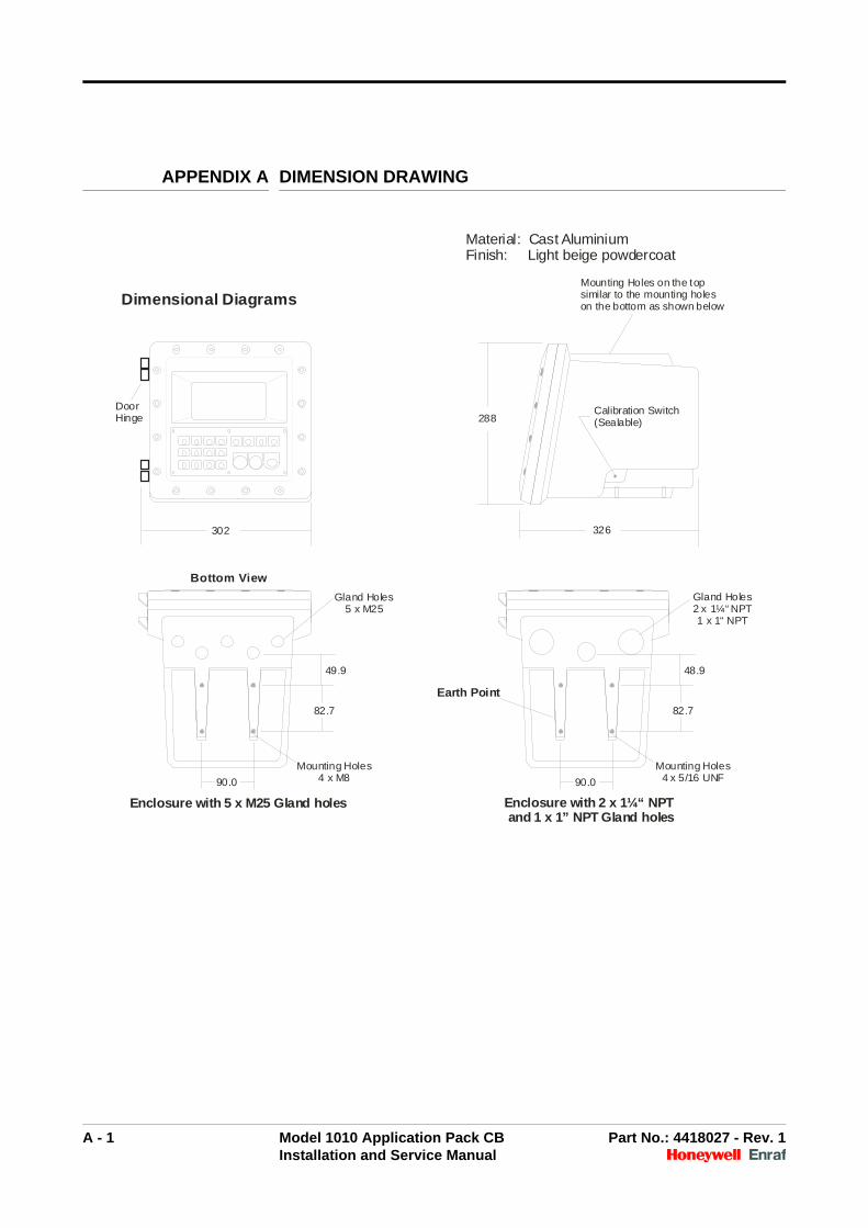
APPENDIX A DIMENSION DRAWING
288
326
Calibration Switch(Sealable)
302
Dimensional Diagrams
Enclosure with 5 x M25 Gland holes Enclosure with 2 x 1¼“ NPT and 1 x 1” NPT Gland holes
82.7 82.7
49.9 48.9
90.0 90.0
Mounting Holes4 x M8
Mounting Holes4 x 5/16 UNF
Gland Holes5 x M25
Gland Holes2 x 1¼“ NPT1 x 1“ NPT
DoorHinge
Mounting Holes on the topsimilar to the mounting holeson the bottom as shown below
Bottom View
Material: Cast AluminiumFinish: Light beige powdercoat
Earth Point

A - 2 Model 1010 Application Pack CB Part No.: 4418027 - Rev. 1Installation and Service Manual
Intentionally left blank.
Glossary - 1 Model 1010 Application Pack CB Part No.: 4418027 - Rev. 1Installation and Service Manual
GLOSSARY
authorisation Type of authorisation. Can be PIN, touch key, RF ID, or NexWatch. Formore information, see chapter 10 “Authorisation Entry Mode” in the1010CB Programming Manual.
authorisation number A number that is programmed into the instrument to allow access to theinstrument after presenting authorisation.
batch Individual loading of product using a single loading arm.
bay The location were a vehicle parks to connect the loading arm andreceive product movements—usually also the location of theinstrument. A typical site can contain multiple bays.
BOL Bill of Lading. A document that is used to acknowledge the receipt of ashipment of goods.
computer A computer, Distributed Control System (DCS), Load Rack Computers(LRC), or Terminal Automation System (TAS) that is attached to aninstrument.
CTPL Correction for the effect of Temperature and Pressure on Liquid.
This is the combined correction for the combined effect of Temperatureand Pressure on Liquid.
The temperature portion of this correction is termed the Correction forthe effect of Temperature on Liquid (CTL).
The pressure portion is termed the Correction for the effect of Pressureon Liquid (CPL).
entry Term formally used to describe a batch.
extended wait period Time, in addition to the wait period, required because a commandprevents the instrument responding for an extended time.
GOV Gross Observed Volume.
GSV Gross Standard Volume.
instrument A 1010 Loading System.
intelligent additiveinjection
An automated additive injection system that connects to the instrumentby a serial communications port. Mini-Pak is one example of this.
load See also “batch”
Honeywell EnrafMini-Pak
See “Mini-Pak”

Glossary - 2 Model 1010 Application Pack CB Part No.: 4418027 - Rev. 1Installation and Service Manual
Mini-Pak An automated additive injection system.
OIML International Organization of Legal Metrology
product stream A stream consisting of a pure product. Both the main and blend streamsare product streams.
proving run One completed batch or loading operation carried out with theAutomated Proving Mode enabled.
ratio blending A process of loading multiple products into a vessel simultaneously. Allproduct streams that make up the loading arm have their own dedicatedflow meter, pump, and control valve. Two independently controlledproduct streams are blended down-stream of the custody meters.
recipe An entity that describes an end product in terms of its primary productsand additives. It also includes clean line volume for blending and flushvolumes for additive injection.
RIT RIT stands for Remote Interaction Terminal. It is designed to aid theoperator in using the instrument without using the keypad.
The RIT panel has 3 keys per arm: START, STOP and ACK. These areconnected to GP inputs of the instrument. The three indicator lampsoutputs per arm are RED, AMBER and GREEN. These are connectedto GP outputs of the instrument.
service display Two line display that shows the loading information for a selectedparameter for the selected arm.
side stream blending This is a form of ratio blending where a minor product stream is meteredand blended into a main product stream upstream from the maincustody transfer meter.
transaction The record of product movement created once the operator isauthorised to use the instrument. A single transaction can be composedof multiple batches, each batch representing the individual productmovements that are required to fill the compartments of a vehicle.
unauthorised flow Flow that is recorded by a meter without being authorised (by anoperator pressing the START key button).
unit address The address byte a computer uses to direct information to the desiredinstrument
vessel A device for containing product, such as a compartment within a trucktanker.
wait period The time the computer waits for a response after sending a command tothe instrument. Generally 300 millisecond.

Glossary - 3 Model 1010 Application Pack CB Part No.: 4418027 - Rev. 1Installation and Service Manual
See also “extended wait period”.
Weights and Measuresswitch
A switch that is mounted on the instrument exterior, that be fitted with atamper seal for W&M requirements.
On the Model 1010 the switch is located on the lower right-hand side ofthe enclosure.

Glossary - 4 Model 1010 Application Pack CB Part No.: 4418027 - Rev. 1Installation and Service Manual
Intentionally left blank.