Embed Size (px)
Citation preview
10/13/200 © NTUST
Last Time
• Compositing
• Painterly Rendering
• Intro to 3D Graphics
• Homework 2, 3 due Oct 13 in class
10/13/200 © NTUST
This Week
• Composing transformations
• 3D Transformations
• Directions
• Rotation
• Geometry 101 – Points, edges, triangles/polygons
• Homogeneous coordinates
• Intro to Viewing
• Viewing Transformations
• Describing Cameras and Views
10/13/200 © NTUST
Coordinate Systems
• The use of coordinate systems is fundamental to computer graphics
• Coordinate systems are used to describe the locations of points in space, and directions in space
• Multiple coordinate systems make graphics algorithms easier to understand and implement
10/13/200 © NTUST
Coordinate Systems (2)
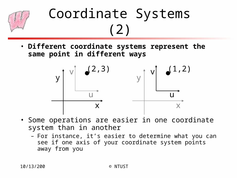
• Different coordinate systems represent the same point in different ways
• Some operations are easier in one coordinate system than in another– For instance, it’s easier to determine what you can see if one axis of
your coordinate system points away from you
x
y(2,3)
u
v
x
y(1,2)
u
v
10/13/200 © NTUST
Transformations
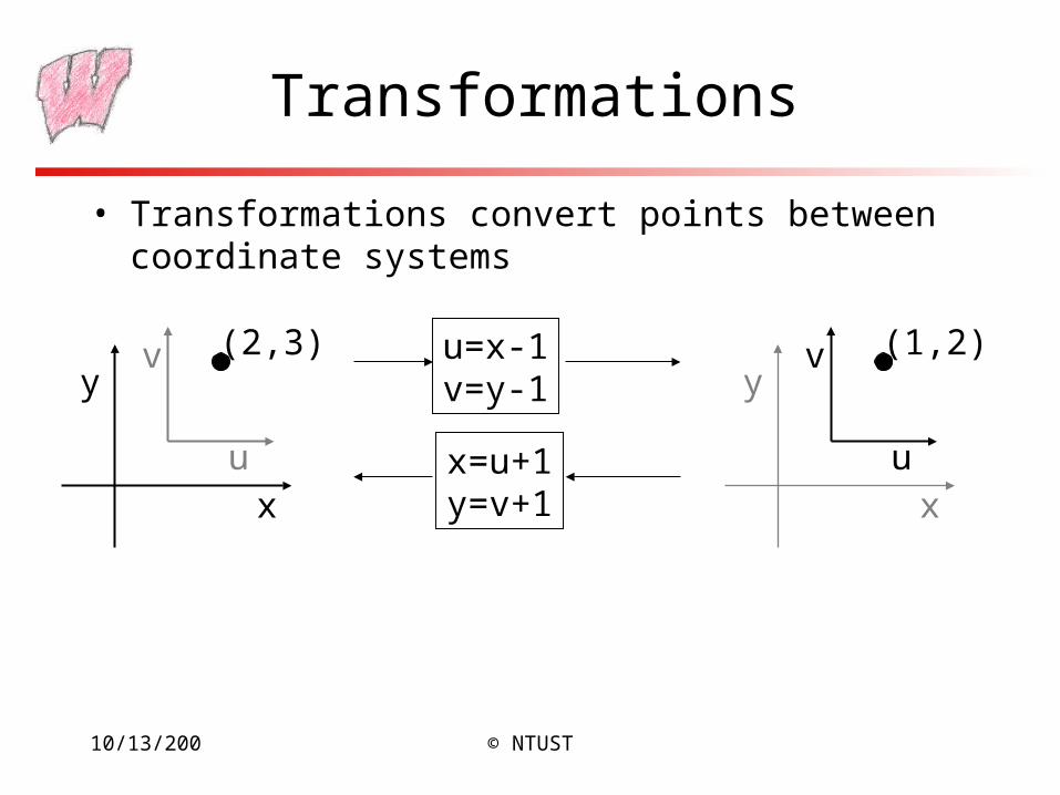
• Transformations convert points between coordinate systems
x
y(2,3)v
x
y(1,2)
u
v
u
u=x-1v=y-1
x=u+1y=v+1
10/13/200 © NTUST
Transformations(Alternate Interpretation)
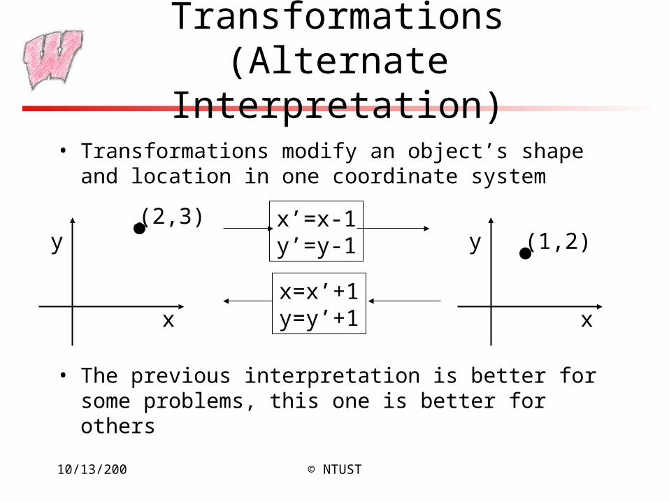
• Transformations modify an object’s shape and location in one coordinate system
• The previous interpretation is better for some problems, this one is better for others
x
y(2,3)
(1,2)
x
yx’=x-1y’=y-1
x=x’+1y=y’+1
10/13/200 © NTUST
2D Affine Transformations
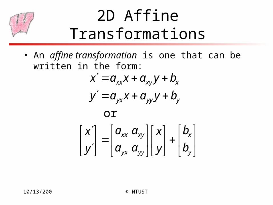
• An affine transformation is one that can be written in the form:
y
x
yyyx
xyxx
yyyyx
xxyxx
b
b
y
x
aa
aa
y
x
byaxay
byaxax
or
10/13/200 © NTUST
Why Affine Transformations?
• Affine transformations are linear– Transforming all the individual points on a line gives the same set
of points as transforming the endpoints and joining them
– Interpolation is the same in either space: Find the halfway point in one space, and transform it. Will get the same result if the endpoints are transformed and then find the halfway point
10/13/200 © NTUST
Composition of Affine Transforms
• Any affine transformation can be composed as a sequence of simple transformations:– Translation
– Scaling (possibly with negative values)
– Rotation
• See Shirley 1.3.6
10/13/200 © NTUST
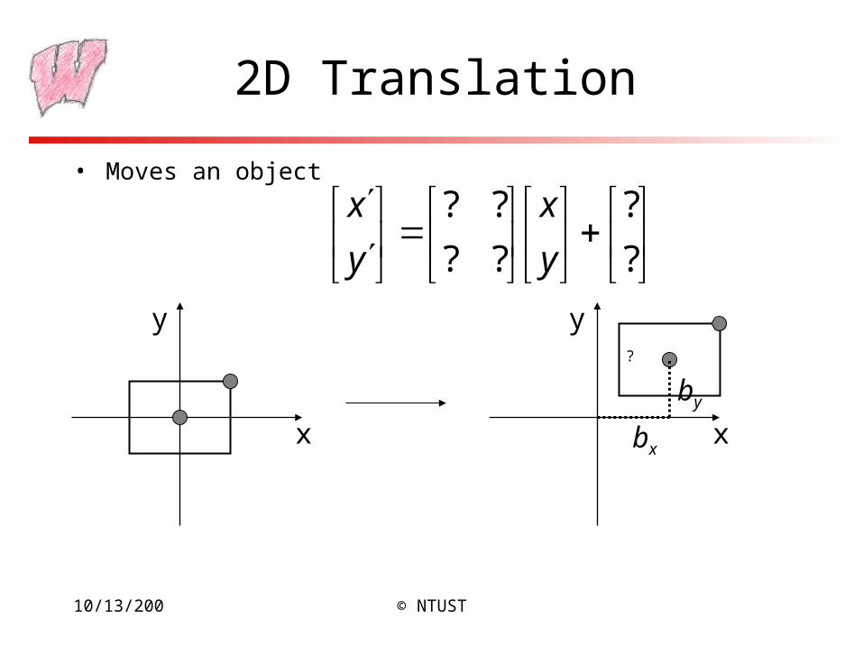
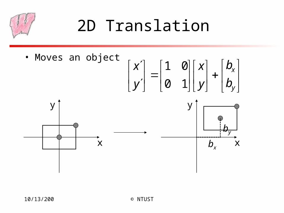
2D Translation
• Moves an object
?
?
??
??
y
x
y
x
x
y
x
y
bx
by
?
10/13/200 © NTUST
2D Translation
• Moves an object
y
x
b
b
y
x
y
x
10
01
x
y
x
y
bx
by
10/13/200 © NTUST
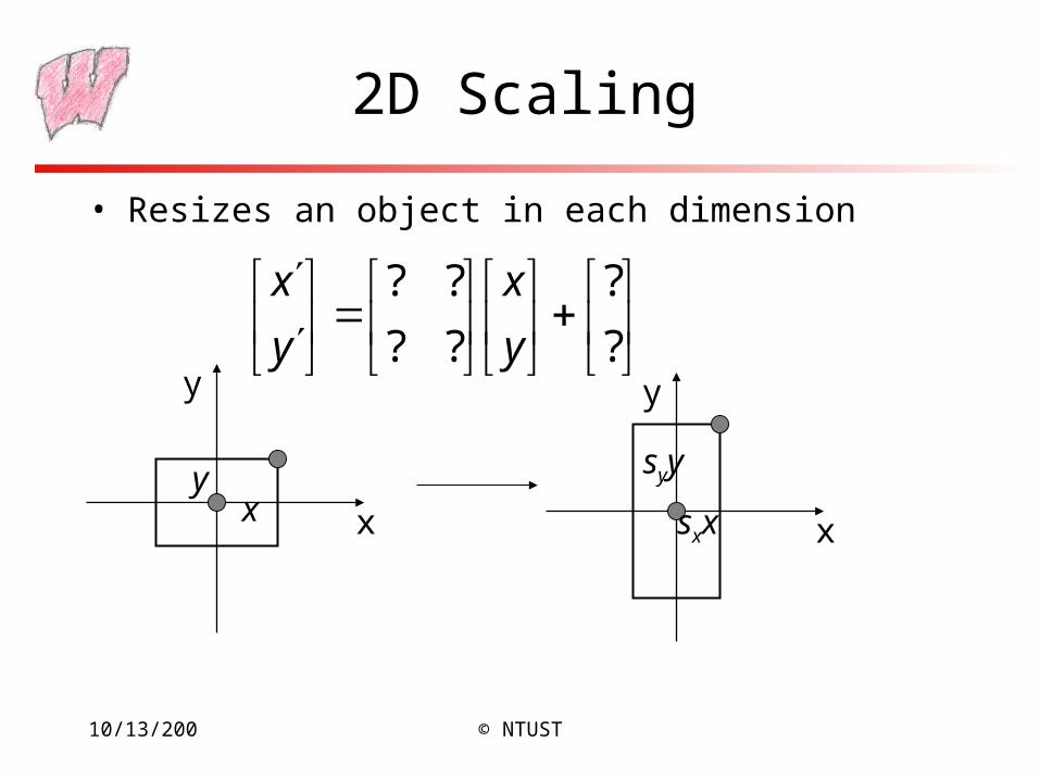
2D Scaling
• Resizes an object in each dimension
x
y
xy
x
y
sxx
syy
?
?
??
??
y
x
y
x
10/13/200 © NTUST
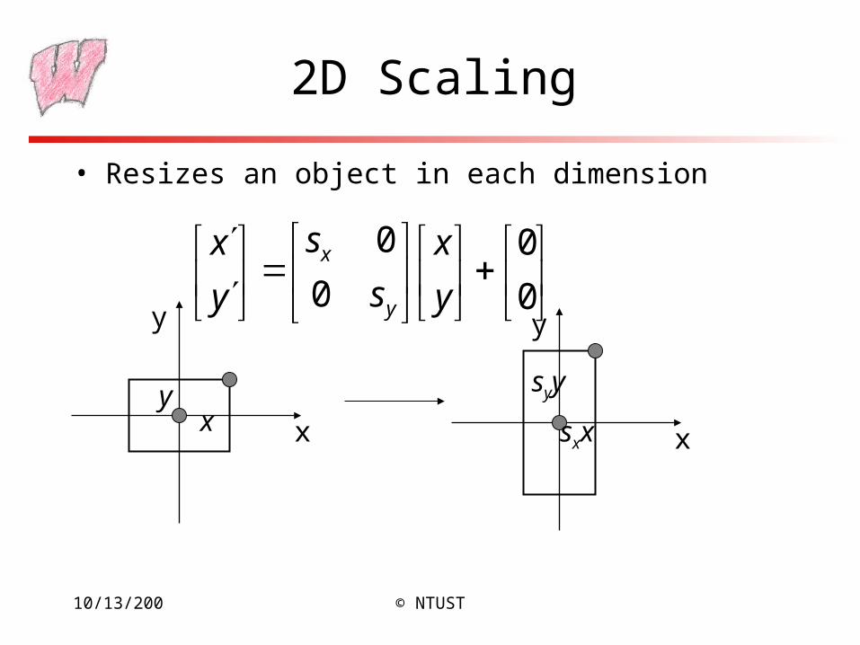
2D Scaling
• Resizes an object in each dimension
x
y
0
0
0
0
y
x
s
s
y
x
y
x
xy
x
y
sxx
syy
10/13/200 © NTUST
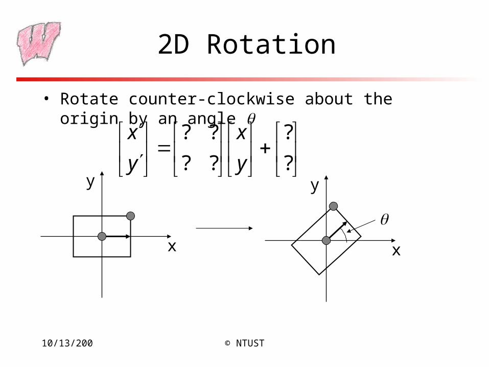
2D Rotation
• Rotate counter-clockwise about the origin by an angle
x
y
x
y
?
?
??
??
y
x
y
x
10/13/200 © NTUST
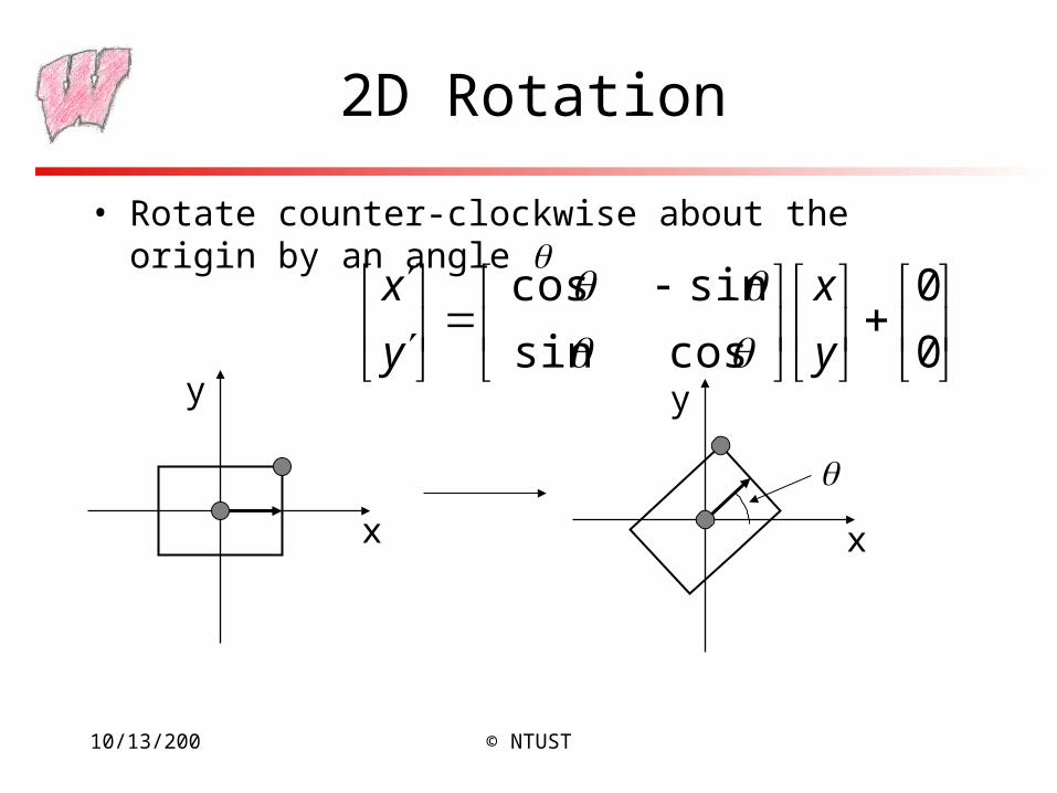
2D Rotation
• Rotate counter-clockwise about the origin by an angle
0
0
cossin
sincos
y
x
y
x
x
y
x
y
10/13/200 © NTUST
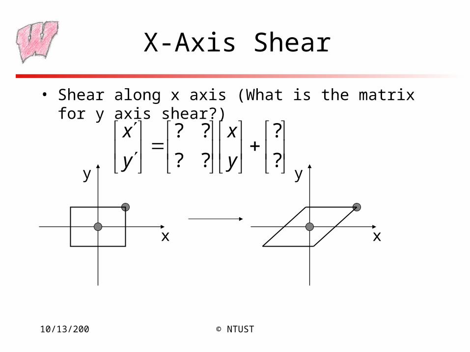
X-Axis Shear
• Shear along x axis (What is the matrix for y axis shear?)
x
y
x
y
?
?
??
??
y
x
y
x
10/13/200 © NTUST
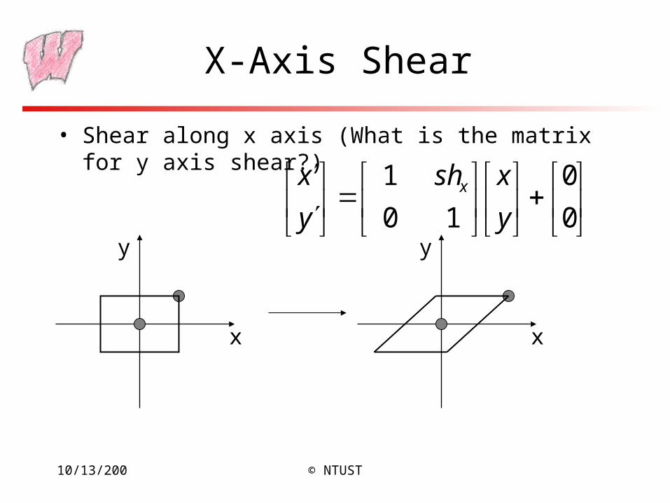
X-Axis Shear
• Shear along x axis (What is the matrix for y axis shear?)
0
0
10
1
y
xsh
y
x x
x
y
x
y
10/13/200 © NTUST
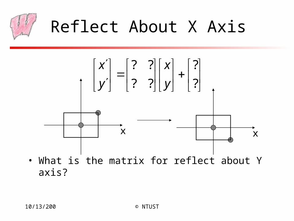
Reflect About X Axis
• What is the matrix for reflect about Y axis?
x x
?
?
??
??
y
x
y
x
10/13/200 © NTUST
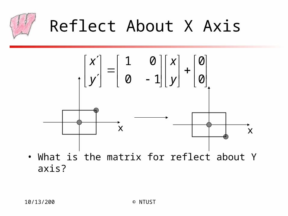
Reflect About X Axis
• What is the matrix for reflect about Y axis?
0
0
10
01
y
x
y
x
x x
10/13/200 © NTUST
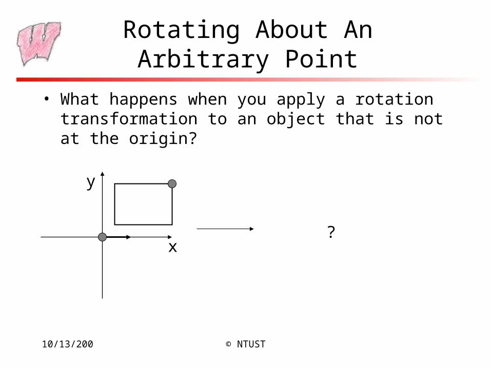
Rotating About An Arbitrary Point
• What happens when you apply a rotation transformation to an object that is not at the origin?
x
y
?
10/13/200 © NTUST
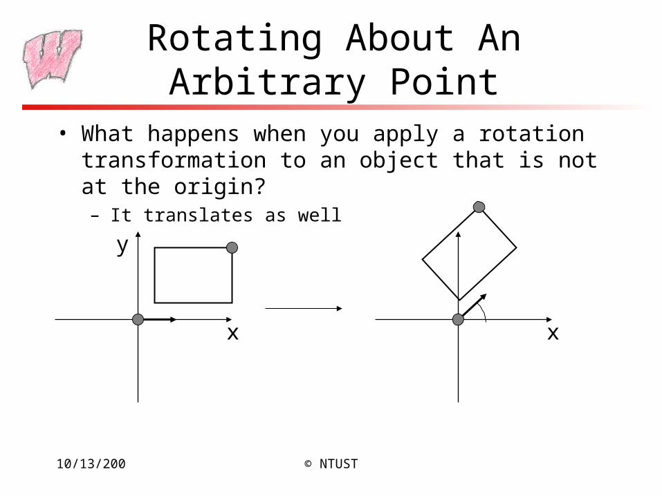
Rotating About An Arbitrary Point
• What happens when you apply a rotation transformation to an object that is not at the origin?– It translates as well
x
y
x
10/13/200 © NTUST
How Do We Fix it?
• How do we rotate an about an arbitrary point?– Hint: we know how to rotate about the origin of a coordinate system
10/13/200 © NTUST
Rotating About An Arbitrary Point
x
y
x
y
x
y
x
y
10/13/200 © NTUST
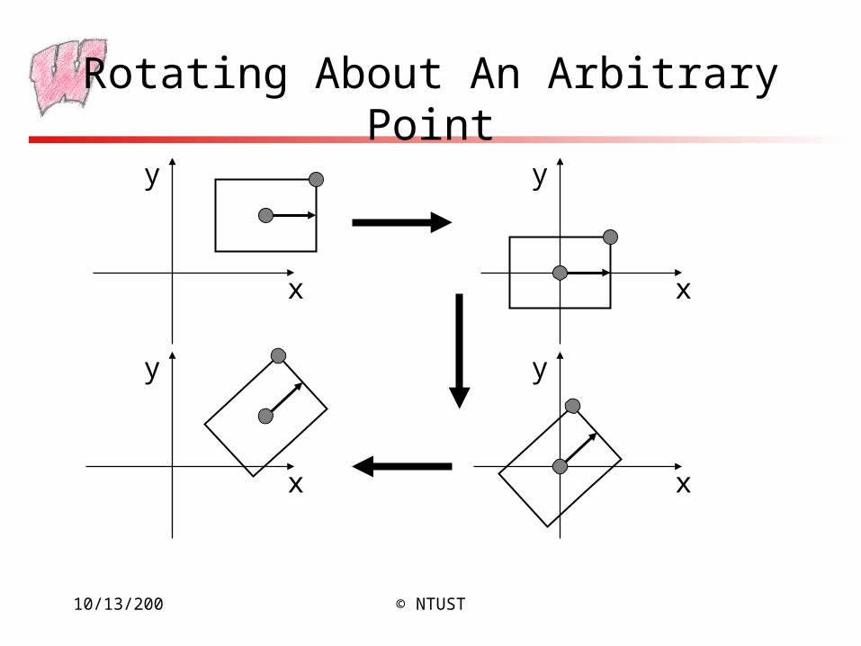
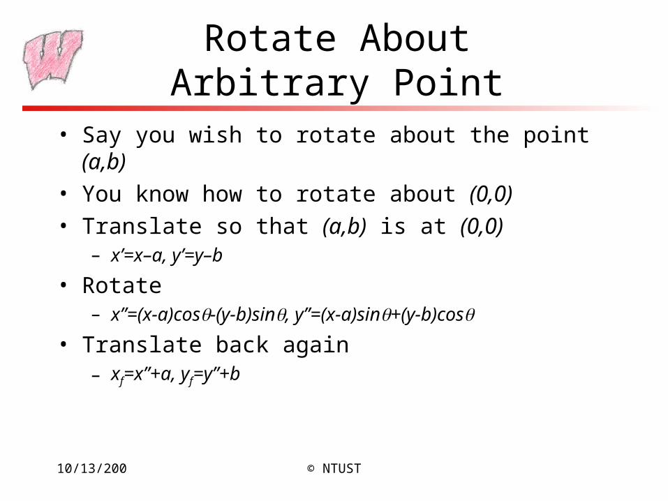
Rotate About Arbitrary Point
• Say you wish to rotate about the point (a,b)
• You know how to rotate about (0,0)
• Translate so that (a,b) is at (0,0)– x’=x–a, y’=y–b
• Rotate– x”=(x-a)cos-(y-b)sin, y”=(x-a)sin+(y-b)cos
• Translate back again– xf=x”+a, yf=y”+b
10/13/200 © NTUST
Scaling an Object not at the Origin
• What happens if you apply the scaling transformation to an object not at the origin?
• Based on the rotating about a point composition, what should you do to resize an object about its own center?
10/13/200 © NTUST
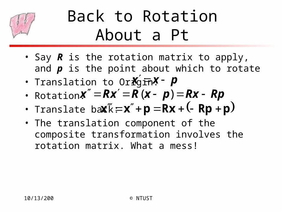
Back to Rotation About a Pt
• Say R is the rotation matrix to apply, and p is the point about which to rotate
• Translation to Origin:
• Rotation:
• Translate back:
• The translation component of the composite transformation involves the rotation matrix. What a mess!
pxx RpRxpxRxRx )(
pRpRxpxx
10/13/200 © NTUST
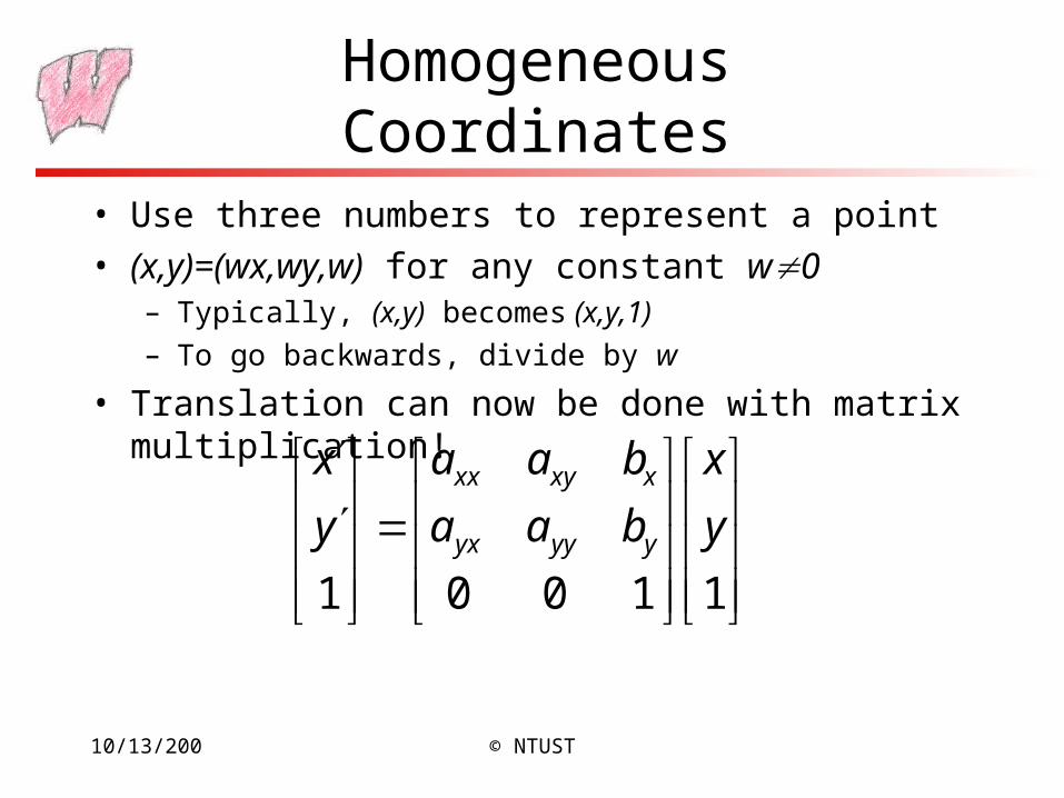
Homogeneous Coordinates
• Use three numbers to represent a point
• (x,y)=(wx,wy,w) for any constant w0– Typically, (x,y) becomes (x,y,1)
– To go backwards, divide by w
• Translation can now be done with matrix multiplication!
11001
y
x
baa
baa
y
x
yyyyx
xxyxx
10/13/200 © NTUST
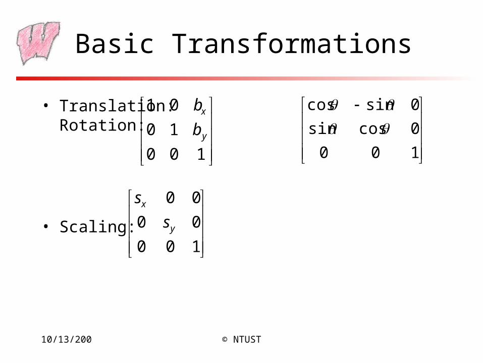
Basic Transformations
• Translation: Rotation:
• Scaling:
100
10
01
y
x
b
b
100
00
00
y
x
s
s
100
0cossin
0sincos
10/13/200 © NTUST
Homogeneous Transform Advantages
• Unified view of transformation as matrix multiplication– Easier in hardware and software
• To compose transformations, simply multiply matrices– Order matters: AB is generally not the same as BA
• Allows for non-affine transformations:– Perspective projections!
– Bends, tapers, many others
10/13/200 © NTUST
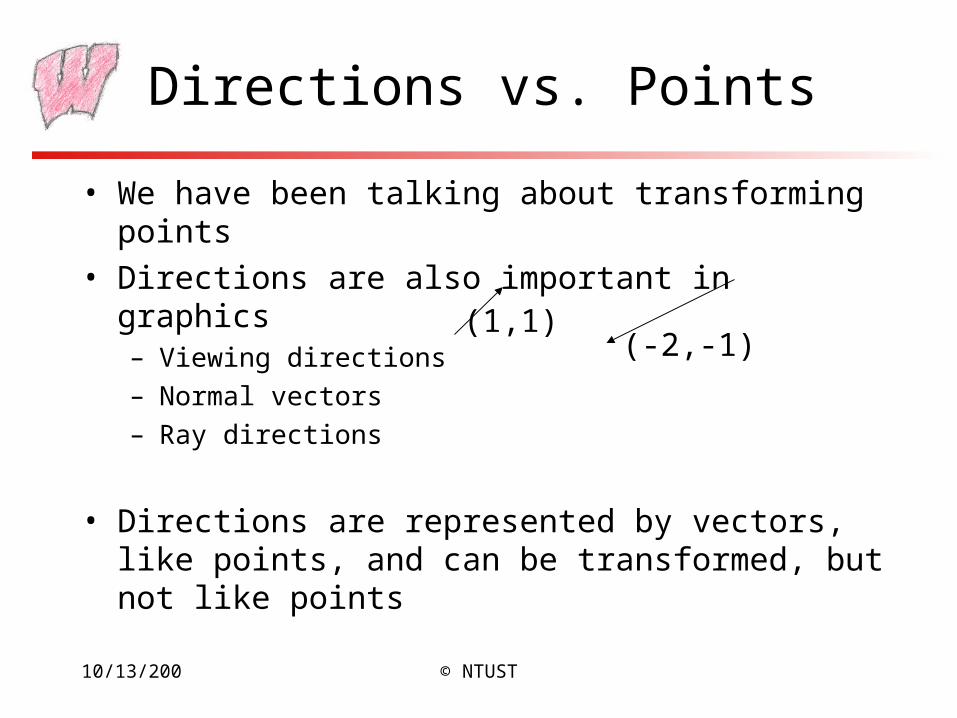
Directions vs. Points
• We have been talking about transforming points
• Directions are also important in graphics– Viewing directions
– Normal vectors
– Ray directions
• Directions are represented by vectors, like points, and can be transformed, but not like points
(1,1)(-2,-1)
10/13/200 © NTUST
Transforming Directions
• Say I define a direction as the difference of two points: d=a–b– This represents the direction of the line between two points
• Now I translate the points by the same amount: a’=a+t, b’=b+t
• How should I transform d?
10/13/200 © NTUST
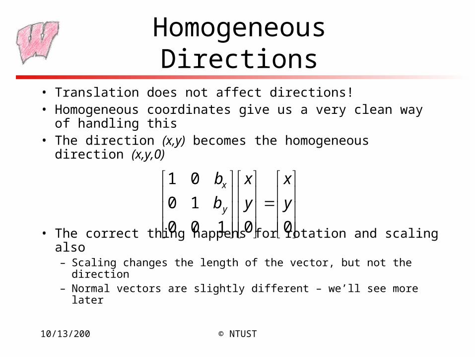
Homogeneous Directions
• Translation does not affect directions!• Homogeneous coordinates give us a very clean way of
handling this• The direction (x,y) becomes the homogeneous direction
(x,y,0)
• The correct thing happens for rotation and scaling also– Scaling changes the length of the vector, but not the direction– Normal vectors are slightly different – we’ll see more later
00100
10
01
y
x
y
x
b
b
y
x
10/13/200 © NTUST
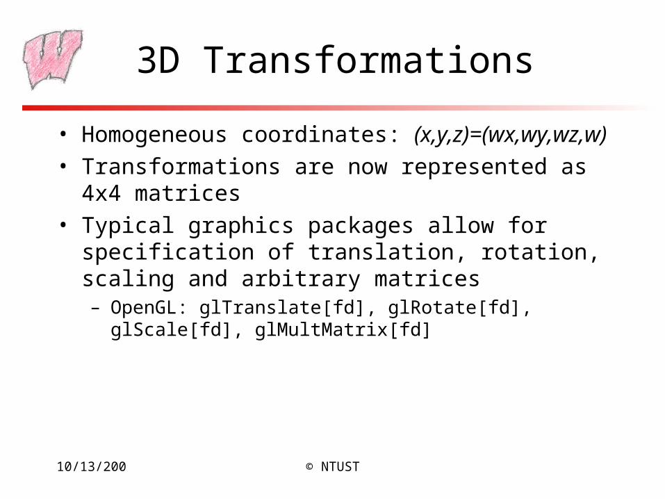
3D Transformations
• Homogeneous coordinates: (x,y,z)=(wx,wy,wz,w)
• Transformations are now represented as 4x4 matrices
• Typical graphics packages allow for specification of translation, rotation, scaling and arbitrary matrices– OpenGL: glTranslate[fd], glRotate[fd], glScale[fd],
glMultMatrix[fd]
10/13/200 © NTUST
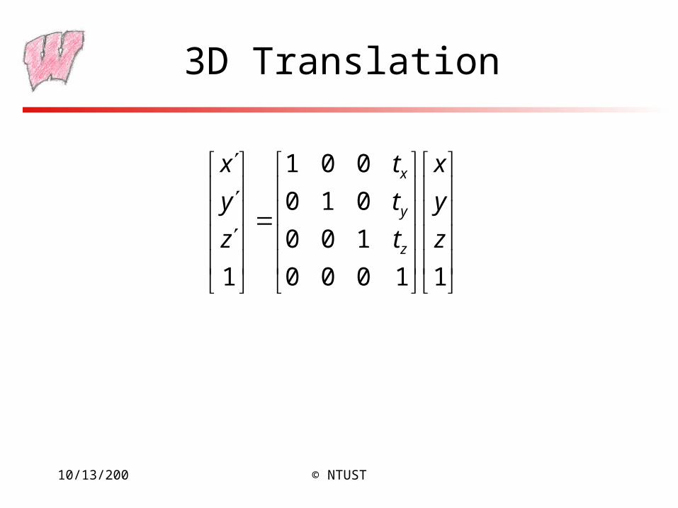
3D Translation
11000
100
010
001
1
z
y
x
t
t
t
z
y
x
z
y
x
10/13/200 © NTUST
3D Rotation
• Rotation in 3D is about an axis in 3D space passing through the origin
• Using a matrix representation, any matrix with an orthonormal top-left 3x3 sub-matrix is a rotation– Rows are mutually orthogonal (0 dot product)
– Determinant is 1
– Implies columns are also orthogonal, and that the transpose is equal to the inverse
10/13/200 © NTUST
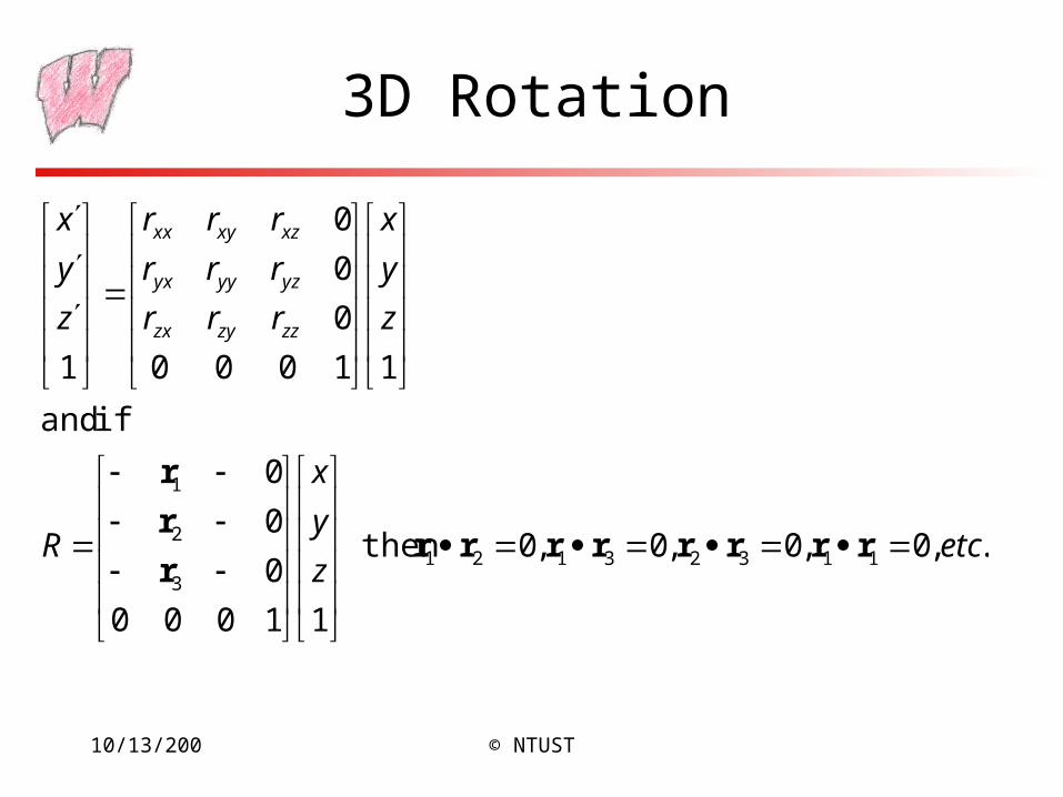
3D Rotation
.,0,0,0,0 then
11000
0
0
0
if and
11000
0
0
0
1
113231213
2
1
etcz
y
x
R
z
y
x
rrr
rrr
rrr
z
y
x
zzzyzx
yzyyyx
xzxyxx
rrrrrrrrr
r
r
10/13/200 © NTUST
Problems with Rotation Matrices
• Specifying a rotation really only requires 3 numbers– Axis is a unit vector, so requires 2 numbers
– Angle to rotate is third number
• Rotation matrix has a large amount of redundancy– Orthonormal constraints reduce degrees of freedom back down to 3
– Keeping a matrix orthonormal is difficult when transformations are combined
• Rotations are a very complex subject, and a detailed discussion is way beyond the scope of this course
10/13/200 © NTUST
Alternative Representations
• Specify the axis and the angle (OpenGL method)– Hard to compose multiple rotations
• Euler angles: Specify how much to rotate about X, then how much about Y, then how much about Z– Hard to think about, and hard to compose
– Any three axes will do e.g. X,Y,X
• Specify the axis, scaled by the angle– Only 3 numbers, called the exponential map
• Quaternions
10/13/200 © NTUST
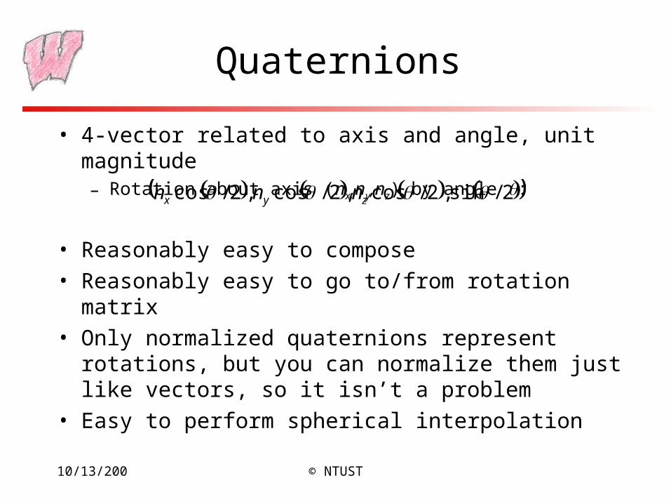
Quaternions
• 4-vector related to axis and angle, unit magnitude– Rotation about axis (nx,ny,nz) by angle :
• Reasonably easy to compose
• Reasonably easy to go to/from rotation matrix
• Only normalized quaternions represent rotations, but you can normalize them just like vectors, so it isn’t a problem
• Easy to perform spherical interpolation
2/sin,2/cos,2/cos,2/cos zyx nnn
10/13/200 © NTUST
Other Rotation Issues
• Rotation is about an axis at the origin– For rotation about an arbitrary axis, use the same trick as in 2D:
Translate the axis to the origin, rotate, and translate back again
• Rotation is not commutative– Rotation order matters
– Experiment to convince yourself of this
10/13/200 © NTUST
Transformation Leftovers
• Scale, shear etc extend naturally from 2D to 3D
• Rotation and Translation are the rigid-body transformations:– Do not change lengths or angles, so a body does not deform when
transformed
10/13/200 © NTUST
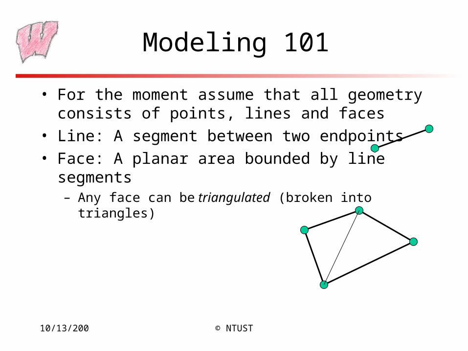
Modeling 101
• For the moment assume that all geometry consists of points, lines and faces
• Line: A segment between two endpoints
• Face: A planar area bounded by line segments– Any face can be triangulated (broken into triangles)
10/13/200 © NTUST
Modeling and OpenGL
• In OpenGL, all geometry is specified by stating which type of object and then giving the vertices that define it
• glBegin(…) …glEnd()• glVertex[34][fdv]
– Three or four components (regular or homogeneous)
– Float, double or vector (eg float[3])
• Chapter 2 of the red book
10/13/200 © NTUST
Rendering
• Generate an image showing the contents of some region of space– The region is called the view volume, and it is defined by the user
• Determine where each object should go in the image– Viewing, Projection
• Determine which pixels should be filled– Rasterization
• Determine which object is in front at each pixel– Hidden surface elimination, Hidden surface removal, Visibility
• Determine what color it is– Lighting, Shading
10/13/200 © NTUST
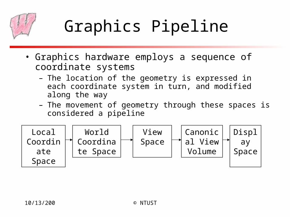
Graphics Pipeline
• Graphics hardware employs a sequence of coordinate systems– The location of the geometry is expressed in each coordinate system
in turn, and modified along the way– The movement of geometry through these spaces is considered a
pipeline
Local Coordinate
Space
World Coordinate
Space
View Space
Canonical View
Volume
Display Space
10/13/200 © NTUST
Local Coordinate Space
• It is easiest to define individual objects in a local coordinate system– For instance, a cube is easiest to define with faces parallel to the
coordinate axes
• Key idea: Object instantiation– Define an object in a local coordinate system
– Use it multiple times by copying it and transforming it into the global system
– This is the only effective way to have libraries of 3D objects
10/13/200 © NTUST
World Coordinate System
• Everything in the world is transformed into one coordinate system - the world coordinate system– It has an origin, and three coordinate directions, x, y, and z
• Lighting is defined in this space– The locations, brightness’ and types of lights
• The camera is defined with respect to this space
• Some higher level operations, such as advanced visibility computations, can be done here
10/13/200 © NTUST
View Space
• Define a coordinate system based on the eye and image plane – the camera– The eye is the center of projection, like the aperture in a camera
– The image plane is the orientation of the plane on which the image should “appear,” like the film plane of a camera
• Some camera parameters are easiest to define in this space– Focal length, image size
• Relative depth is captured by a single number in this space– The “normal to image plane” coordinate
10/13/200 © NTUST
Canonical View Volume
• Canonical View Space: A cube, with the origin at the center, the viewer looking down –z, x to the right, and y up– Canonical View Volume is the cube: [-1,1]×[-1,1]×[-1,1]– Variants (later) with viewer looking down +z and z from 0-1– Only things that end up inside the canonical volume can appear in
the window
• Tasks: Parallel sides and unit dimensions make many operations easier– Clipping – decide what is in the window– Rasterization - decide which pixels are covered– Hidden surface removal - decide what is in front– Shading - decide what color things are
10/13/200 © NTUST
Window Space
• Window Space: Origin in one corner of the “window” on the screen, x and y match screen x and y
• Windows appear somewhere on the screen– Typically you want the thing you are drawing to appear in your
window
– But you may have no control over where the window appears
• You want to be able to work in a standard coordinate system – your code should not depend on where the window is
• You target Window Space, and the windowing system takes care of putting it on the screen
10/13/200 © NTUST
Canonical Window Transform
• Problem: Transform the Canonical View Volume into Window Space (real screen coordinates)– Drop the depth coordinate and translate
– The graphics hardware and windowing system typically take care of this – but we’ll do the math to get you warmed up
• The windowing system adds one final transformation to get your window on the screen in the right place
10/13/200 © NTUST
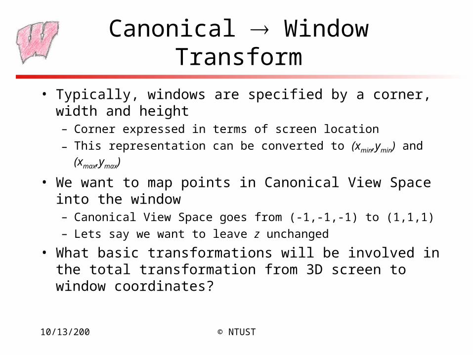
Canonical Window Transform
• Typically, windows are specified by a corner, width and height– Corner expressed in terms of screen location
– This representation can be converted to (xmin,ymin) and (xmax,ymax)
• We want to map points in Canonical View Space into the window– Canonical View Space goes from (-1,-1,-1) to (1,1,1)
– Lets say we want to leave z unchanged
• What basic transformations will be involved in the total transformation from 3D screen to window coordinates?
10/13/200 © NTUST
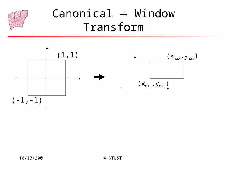
Canonical Window Transform
(-1,-1)
(1,1)
(xmin,ymin)
(xmax,ymax)
10/13/200 © NTUST
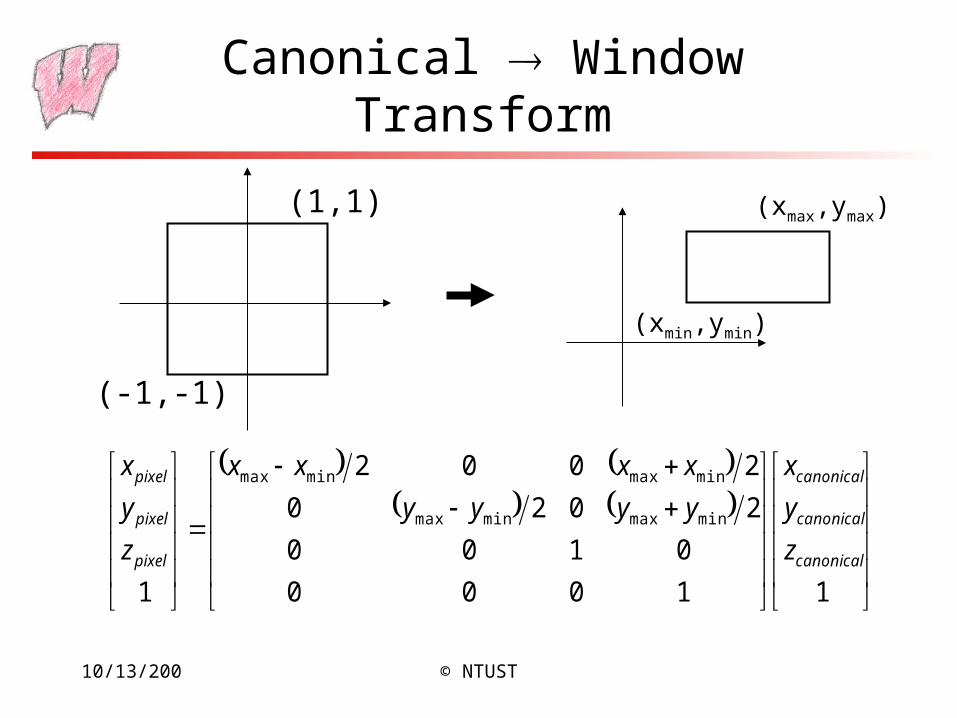
Canonical Window Transform
(-1,-1)
(1,1)
(xmin,ymin)
(xmax,ymax)
11000
0100
2020
2002
1
minmaxminmax
minmaxminmax
canonical
canonical
canonical
pixel
pixel
pixel
z
y
x
yyyy
xxxx
z
y
x
10/13/200 © NTUST
Canonical Window Transform
• You almost never have to worry about the canonical to window transform
• In OpenGL, you tell it which part of your window to draw in – relative to the window’s coordinates– That is, you tell it where to put the canonical view volume
– You must do this whenever the window changes size
– Window (not the screen) has origin at bottom left– glViewport(minx, miny, maxx, maxy)– Typically: glViewport(0, 0, width, height)fills the entire
window with the image
– Why might you not fill the entire window?
• The textbook derives a different transform, but the same idea
10/13/200 © NTUST
View Volumes
• Only stuff inside the Canonical View Volume gets drawn– The window is of finite size, and we can only store a finite number
of pixels
– We can only store a discrete, finite range of depths• Like color, only have a fixed number of bits at each pixel
– Points too close or too far away will not be drawn
– But, it is inconvenient to model the world as a unit box
• A view volume is the region of space we wish to transform into the Canonical View Volume for drawing– Only stuff inside the view volume gets drawn
– Describing the view volume is a major part of defining the view
10/13/200 © NTUST
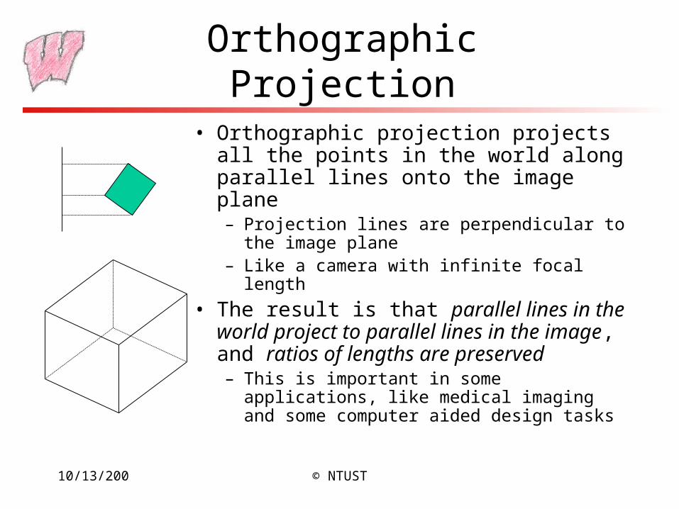
Orthographic Projection
• Orthographic projection projects all the points in the world along parallel lines onto the image plane– Projection lines are perpendicular to the image
plane– Like a camera with infinite focal length
• The result is that parallel lines in the world project to parallel lines in the image, and ratios of lengths are preserved– This is important in some applications, like
medical imaging and some computer aided design tasks
10/13/200 © NTUST
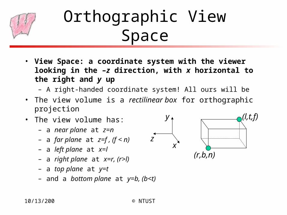
Orthographic View Space
z
y
x
• View Space: a coordinate system with the viewer looking in the –z direction, with x horizontal to the right and y up– A right-handed coordinate system! All ours will be
• The view volume is a rectilinear box for orthographic projection
• The view volume has:– a near plane at z=n
– a far plane at z=f , (f < n)
– a left plane at x=l
– a right plane at x=r, (r>l)
– a top plane at y=t
– and a bottom plane at y=b, (b<t)
(r,b,n)
(l,t,f)
10/13/200 © NTUST
Rendering the Volume
• To find out where points end up on the screen, we must transform View Space into Canonical View Space– We know how to draw Canonical View Space on the screen
• This transformation is “projection”
• The mapping looks similar to the one for Canonical to Window …
10/13/200 © NTUST
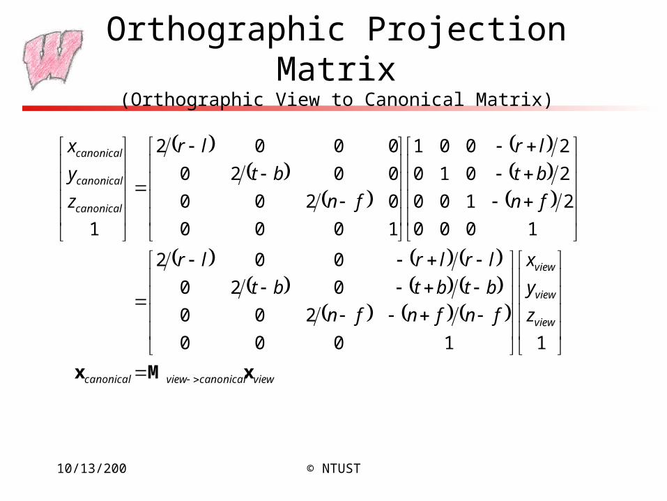
Orthographic Projection Matrix(Orthographic View to Canonical Matrix)
viewcanonicalviewcanonical
view
view
view
canonical
canonical
canonical
z
y
x
fnfnfn
btbtbt
lrlrlr
fn
bt
lr
fn
bt
lr
z
y
x
xMx
11000
200
020
002
1000
2100
2010
2001
1000
0200
0020
0002
1
10/13/200 © NTUST
Defining Cameras
• View Space is the camera’s local coordinates– The camera is in some location
– The camera is looking in some direction
– It is tilted in some orientation
• It is inconvenient to model everything in terms of View Space– Biggest problem is that the camera might be moving – we don’t
want to have to explicitly move every object too
• We specify the camera, and hence View Space, with respect to World Space– How can we specify the camera?
10/13/200 © NTUST
Specifying a View
• The location of View Space with respect to World Space– A point in World Space for the origin of View Space, (ex,ey,ez)
• The direction in which we are looking: gaze direction– Specified as a vector: (gx,gy,gz)
– This vector will be normal to the image plane
• A direction that we want to appear up in the image– (upx,upy,upz), this vector does not have to be perpendicular to g
• We also need the size of the view volume – l,r,t,b,n,f– Specified with respect to the eye and image plane, not the world
10/13/200 © NTUST
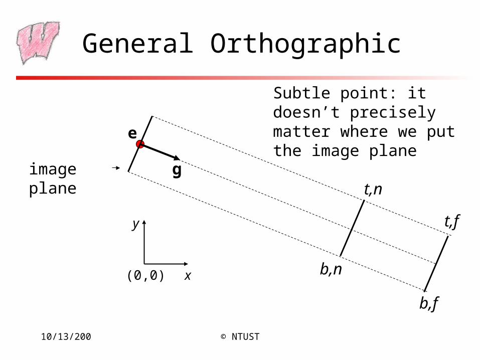
General Orthographic
(0,0) x
y
e
image plane g
b,n
b,f
t,n
t,f
Subtle point: it doesn’t precisely matter where we put the image plane
10/13/200 © NTUST
Getting there…
• We wish to end up in View Space, so we need a coordinate system with:– A vector toward the viewer, View Space z
– A vector pointing right in the image plane, View Space x
– A vector pointing up in the image plane, View Space y
– The origin at the eye, View Space (0,0,0)
• We must:– Say what each of these vectors are in World Space
– Transform points from the World Space into View Space
– We can then apply the orthographic projection to get to Canonical View Space, and so on
10/13/200 © NTUST
View Space in World Space
• Given our camera definition, in World Space:– Where is the origin of view space? It will transform into (0,0,0)view
– What is the normal to the view plane, w? It will become zview
– How do we find the right vector, u? It will become xview
– How do we find the up vector, v? It will become yview
• Given these points, how do we do the transformation?
10/13/200 © NTUST
View Space
• The origin is at the eye: (ex,ey,ez)
• The normal vector is the normalized viewing direction:
• We know which way up should be, and we know we have a right handed system, so u=up×w, normalized:
• We have two vectors in a right handed system, so to get the third: v=w×u
gw ˆ
u
10/13/200 © NTUST
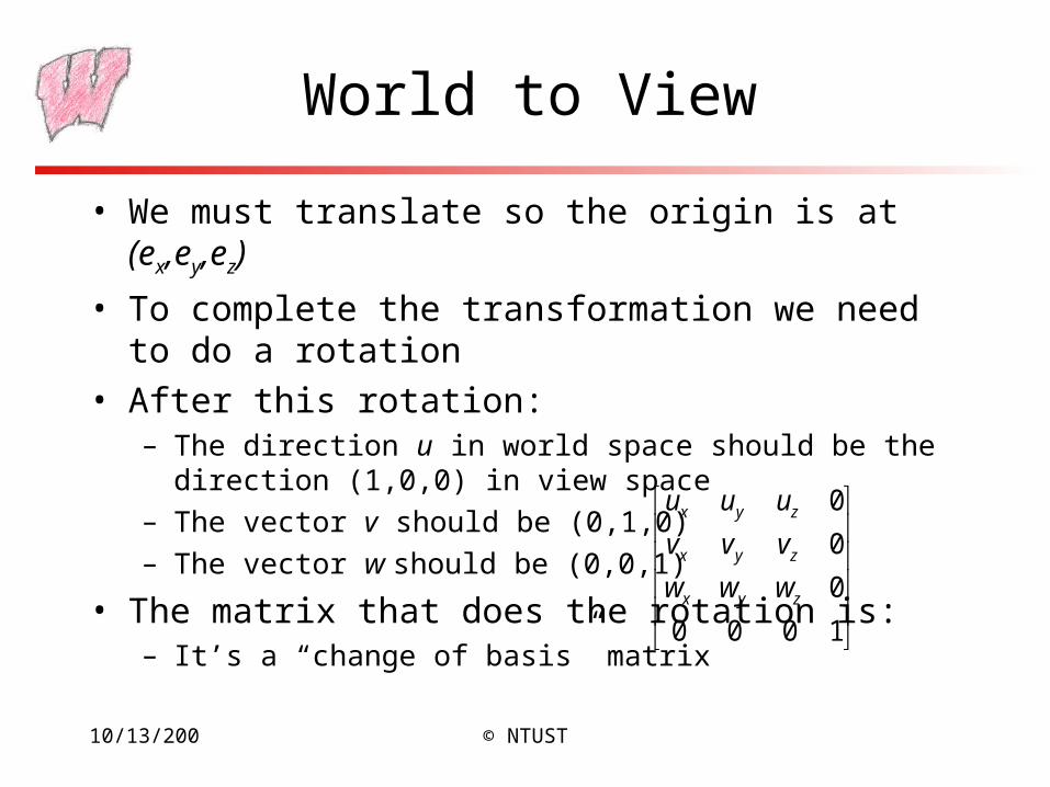
World to View
• We must translate so the origin is at (ex,ey,ez)
• To complete the transformation we need to do a rotation
• After this rotation:– The direction u in world space should be the direction (1,0,0) in
view space
– The vector v should be (0,1,0)
– The vector w should be (0,0,1)
• The matrix that does the rotation is:– It’s a “change of basis” matrix
1000
0
0
0
zyx
zyx
zyx
www
vvv
uuu
10/13/200 © NTUST
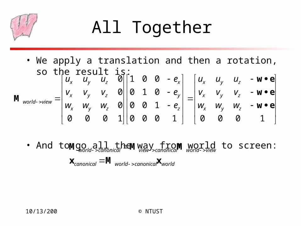
All Together
• We apply a translation and then a rotation, so the result is:
• And to go all the way from world to screen:
10001000
100
010
001
1000
0
0
0
ew
ew
ew
Mzyx
zyx
zyx
z
y
x
zyx
zyx
zyx
viewworld www
vvv
uuu
e
e
e
www
vvv
uuu
worldcanonicalworldcanonical
viewworldcanonicalviewcanonicalworld
xMx
MMM
10/13/200 © NTUST
OpenGL and Transformations
• OpenGL internally stores two matrices that control viewing of the scene– The GL_MODELVIEW matrix is intended to capture all the transformations
up to view space
– The GL_PROJECTION matrix captures the view to canonical conversion
• You also specify the mapping from the canonical view volume into window space– Directly through a glViewport function call
• Matrix calls, such as glRotate, multiply some matrix M onto the current matrix C, resulting in CM– Set view transformation first, then set transformations from local to world
space – last one set is first one applied
– This is the convenient way for modeling, as we will see
10/13/200 © NTUST
OpenGL Camera
• The default OpenGL image plane has u aligned with the x axis, v aligned with y, and n aligned with z– Means the default camera looks along the negative z axis
– Makes it easy to do 2D drawing (no need for any view transformation)
• glOrtho(…) sets the view->canonical matrix– Modifies the GL_PROJECTION matrix
• gluLookAt(…) sets the world->view matrix– Takes an image center point, a point along the viewing direction and an up
vector
– Multiplies a world->view matrix onto the current GL_MODELVIEW matrix
– You could do this yourself, using glMultMatrix(…) with the matrix from the previous slides
10/13/200 © NTUST
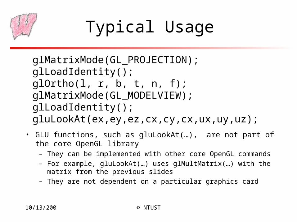
Typical Usage
• GLU functions, such as gluLookAt(…), are not part of the core OpenGL library – They can be implemented with other core OpenGL commands
– For example, gluLookAt(…) uses glMultMatrix(…) with the matrix from the previous slides
– They are not dependent on a particular graphics card
glMatrixMode(GL_PROJECTION);glLoadIdentity();glOrtho(l, r, b, t, n, f);glMatrixMode(GL_MODELVIEW);glLoadIdentity();gluLookAt(ex,ey,ez,cx,cy,cx,ux,uy,uz);
10/13/200 © NTUST
Left vs Right Handed View Space
• You can define u as right, v as up, and n as toward the viewer: a right handed system uv=w– Advantage: Standard mathematical way of doing things
• You can also define u as right, v as up and n as into the scene: a left handed system vu=w– Advantage: Bigger n values mean points are further away
• OpenGL is right handed
• Many older systems, notably the Renderman standard developed by Pixar, are left handed