Embed Size (px)
Citation preview
04/19/23 1
University of North Carolina-CharlotteUniversity of North Carolina-Charlotte
INTRODUCTION TO DIGITAL ACTUATORSINTRODUCTION TO DIGITAL ACTUATORS(Stepper and Servo Motors)(Stepper and Servo Motors)
Gurunath AthalyeGurunath Athalye
04/19/23 2
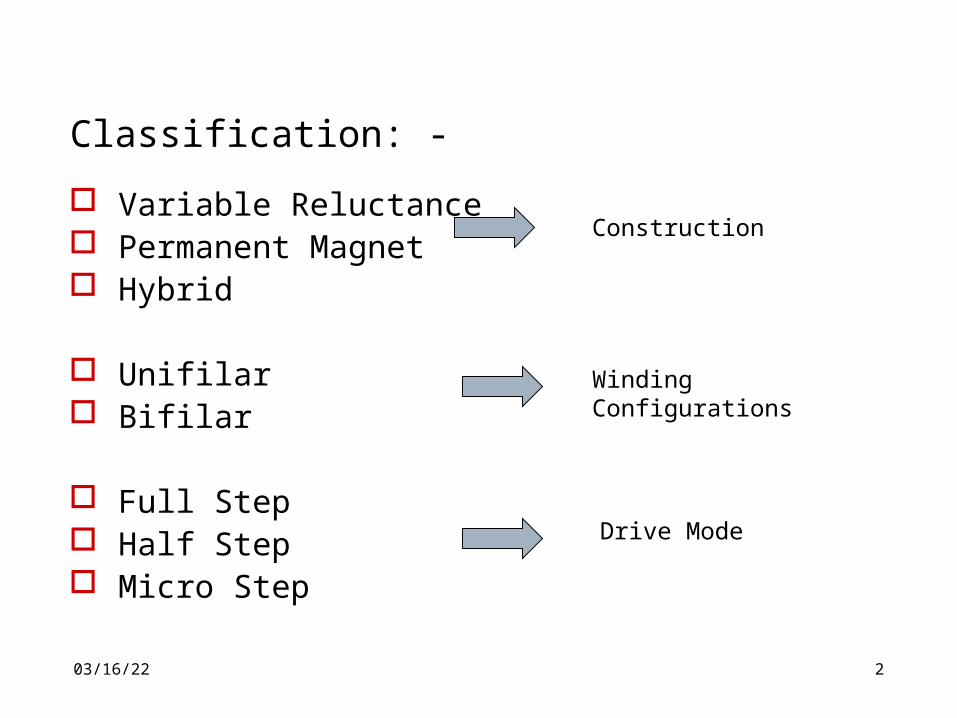
Classification: -
Variable Reluctance Permanent Magnet Hybrid
Unifilar Bifilar
Full Step Half Step Micro Step
Construction
Winding Configurations
Drive Mode
04/19/23 3
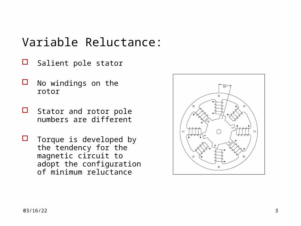
Variable Reluctance:
Salient pole stator
No windings on the rotor Stator and rotor pole
numbers are different Torque is developed by the
tendency for the magnetic circuit to adopt the configuration of minimum reluctance
04/19/23 4
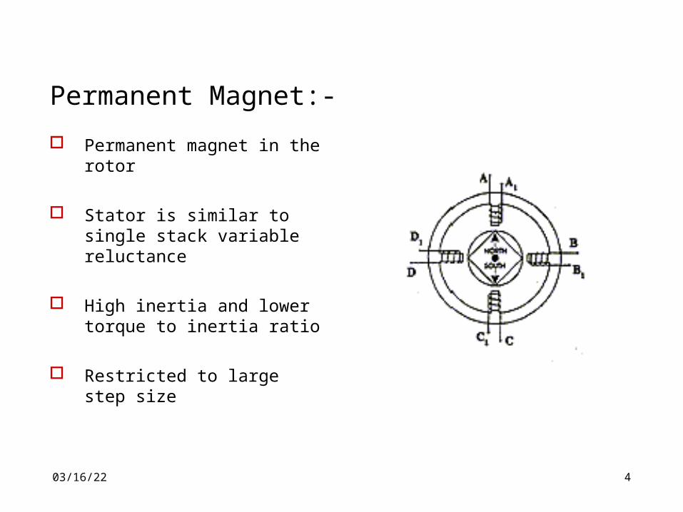
Permanent Magnet:-
Permanent magnet in the rotor
Stator is similar to single stack variable reluctance
High inertia and lower torque to inertia ratio
Restricted to large step size
04/19/23 5
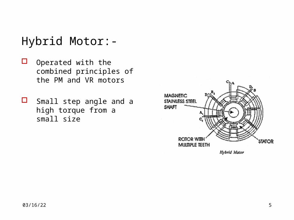
Hybrid Motor:-
Operated with the combined principles of the PM and VR motors
Small step angle and a high torque from a small size
04/19/23 6
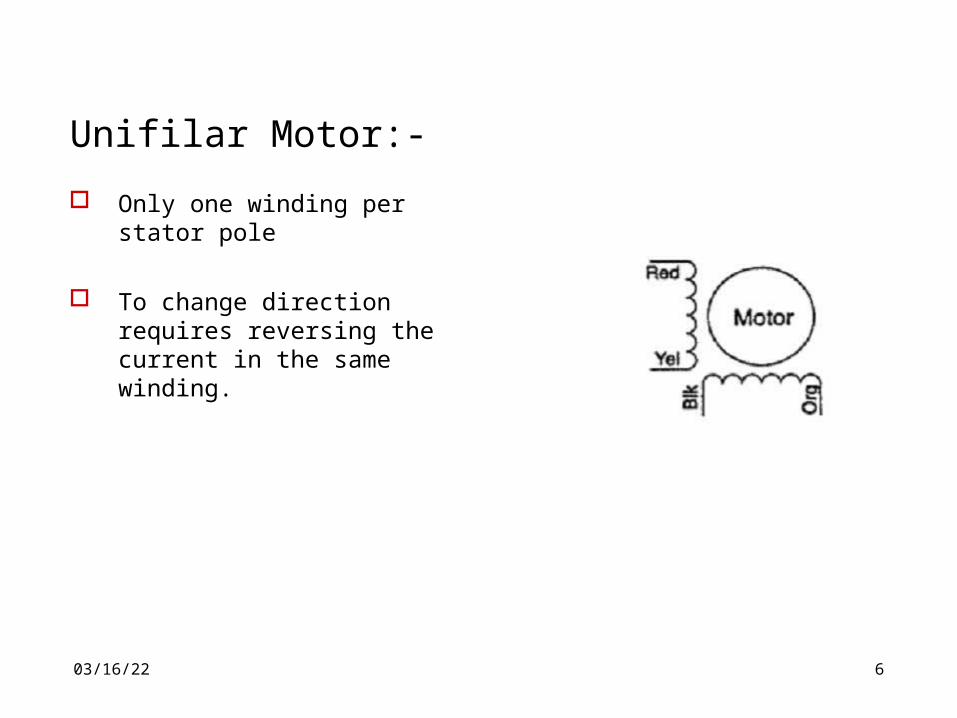
Unifilar Motor:-
Only one winding per stator pole
To change direction requires reversing the current in the same winding.
04/19/23 7
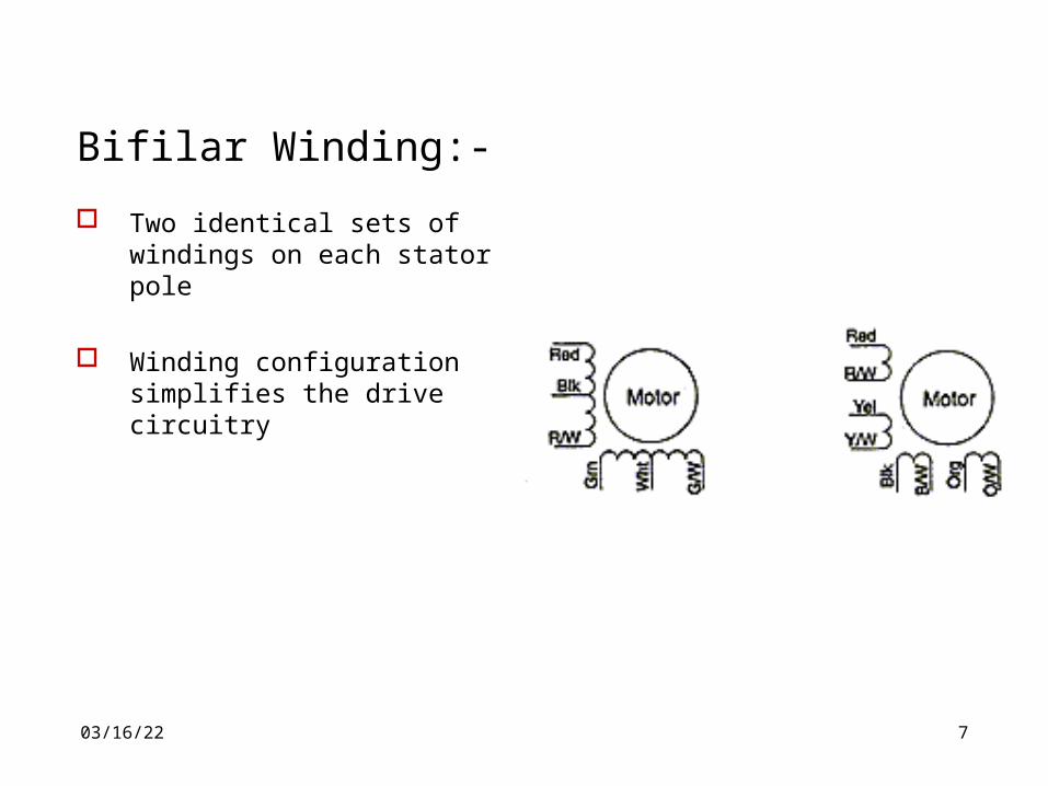
Bifilar Winding:-
Two identical sets of windings on each stator pole
Winding configuration simplifies the drive circuitry
04/19/23 8
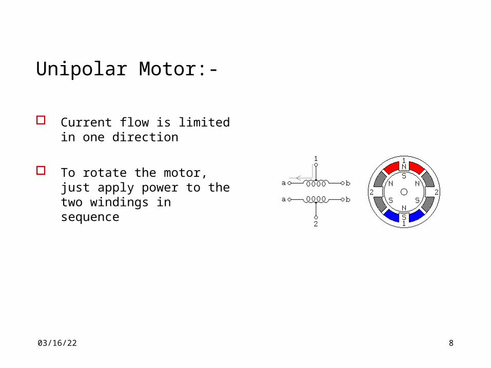
Unipolar Motor:-
Current flow is limited in one direction
To rotate the motor, just apply power to the two windings in sequence
04/19/23 9
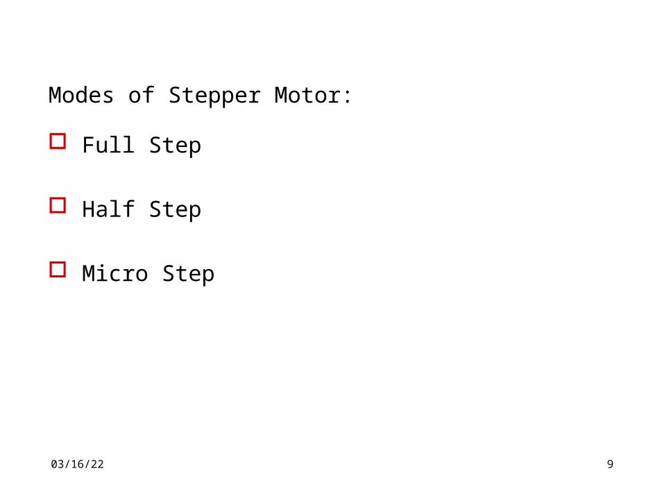
Modes of Stepper Motor:
Full Step
Half Step
Micro Step
04/19/23 10
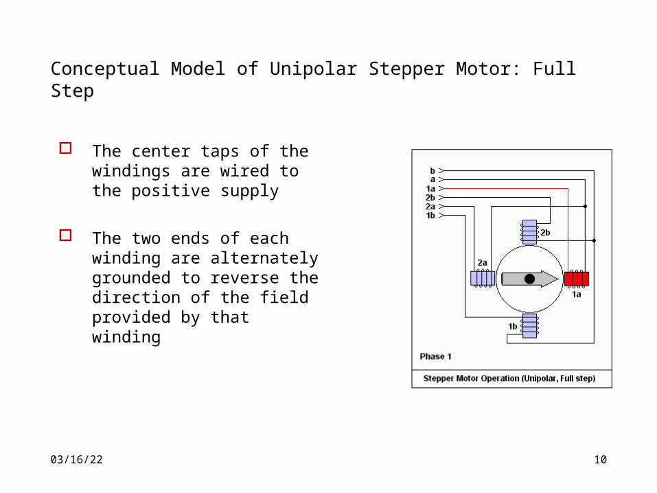
Conceptual Model of Unipolar Stepper Motor: Full Step
The center taps of the windings are wired to the positive supply
The two ends of each winding are alternately grounded to reverse the direction of the field provided by that winding
04/19/23 11
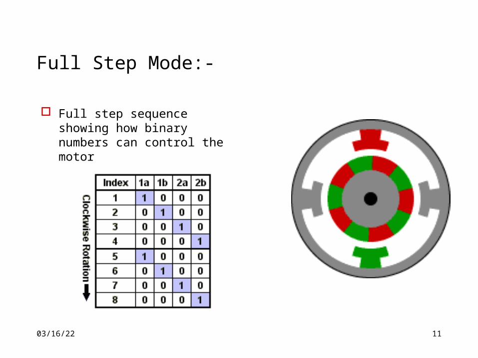
Full Step Mode:-
Full step sequence showing how binary numbers can control the motor

04/19/23 12
Conceptual Model of Unipolar Stepper Motor: Half Step
Same circuitry with different winding sequence
Two windings are energized at the same instance
04/19/23 13
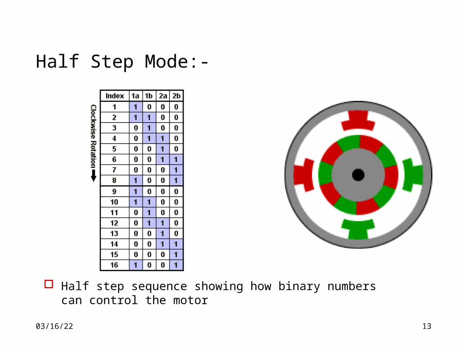
Half Step Mode:-
Half step sequence showing how binary numbers can control the motor
04/19/23 14
Micro Stepping Mode:-
Positional resolution is limited because of the mechanical design of the unit
It allows a stepping motor to stop and hold a position between the full or half-step positions
The jerky character of low speed stepping motor operation and the noise at intermediate speeds
04/19/23 15
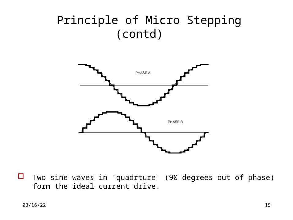
Principle of Micro Stepping(contd)
Two sine waves in 'quadrture' (90 degrees out of phase) form the ideal current drive.
04/19/23 16
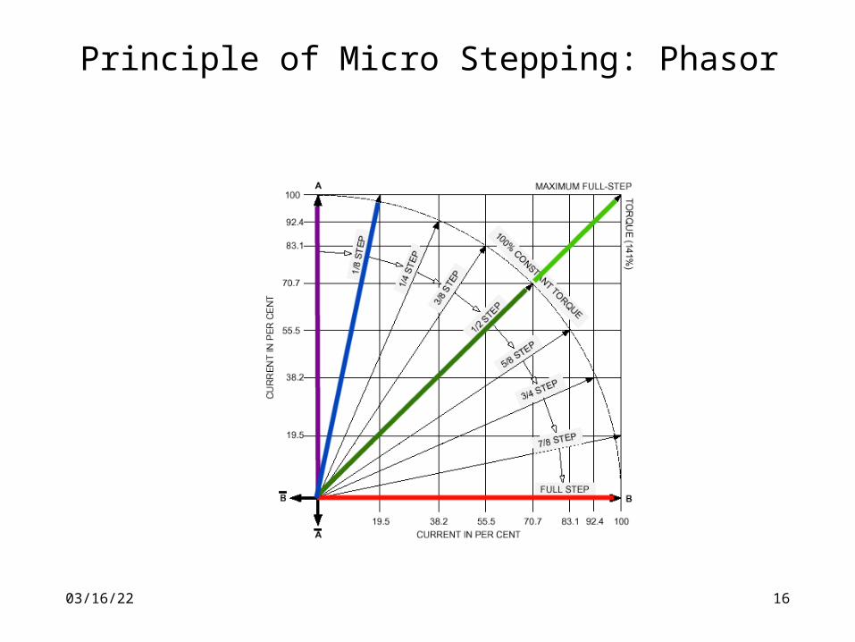
Principle of Micro Stepping: Phasor
04/19/23 17
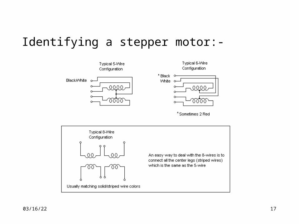
Identifying a stepper motor:-
04/19/23 18
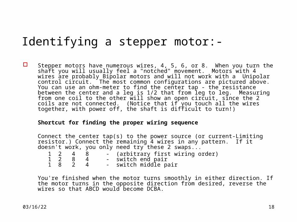
Identifying a stepper motor:-
Stepper motors have numerous wires, 4, 5, 6, or 8. When you turn the shaft you will usually feel a "notched" movement. Motors with 4 wires are probably Bipolar motors and will not work with a Unipolar control circuit. The most common configurations are pictured above. You can use an ohm-meter to find the center tap - the resistance between the center and a leg is 1/2 that from leg to leg. Measuring from one coil to the other will show an open circuit, since the 2 coils are not connected. (Notice that if you touch all the wires together, with power off, the shaft is difficult to turn!)
Shortcut for finding the proper wiring sequence
Connect the center tap(s) to the power source (or current-Limiting resistor.) Connect the remaining 4 wires in any pattern. If it doesn't work, you only need try these 2 swaps...
1 2 4 8 - (arbitrary first wiring order) 1 2 8 4 - switch end pair 1 8 2 4 - switch middle pair
You're finished when the motor turns smoothly in either direction. If the motor turns in the opposite direction from desired, reverse the wires so that ABCD would become DCBA.
04/19/23 19
References:- Dr. James M. Conrad
http://www.coe.uncc.edu/~jmconradaccessed : February 2006
Douglas W. Jones, Control of Stepping Motors – A Tutorial, http://www.cs.uiowa.edu/~jones/step/accessed : February 2006
http://www.stepperworld.com accessed : February 2006
http://hibp.ecse.rpi.edu/~connor/education/IEE/IEE-Lec8.pptaccessed : February 2006
http://www.tpub.com/content/neets/14187/css/14187_95.htmaccessed : February 2006