Embed Size (px)
Citation preview
Sensing and Control, 11 West Spring Street, Freeport, Illinois 61032
Printed in U.S.A. © Copyright 2000—Honeywell
10260A Herculine® SeriesActuatorNon-Contact Position Sensing!
62-86-03-1010/00
Page 1 of 12
SpecificationOverview
To operate with maximum efficiencyand improve process uptime, state-of-the-art control systems requireaccurate, responsive, and repeatableactuation of final control devices.Actuators are often overlooked whenconsidering maintenance and ancillarysupport costs, yet they play animportant role in system performanceand can directly impact yourcompany’s bottom line.
Honeywell's 10260A medium torqueindustrially rated rotary actuator isengineered for exceptional reliability,accurate positioning, and lowmaintenance. Designed for veryprecise positioning of dampers andquarter turn valves, the 10260Aperforms especially well in extremelydemanding environments requiringcontinuous-duty, high reliability, andlow maintenance. Typical applicationsinclude furnace pressure dampers,fuel/air ratio valves, windbox dampers,coal mill dampers, scoop tubes, andFluid Gyrols.
Actuator Operation
Spur gears and a single reductionworm/worm gear combine with asynchronous induction AC motor foraccurate and repeatable positioning offinal control elements.
The worm/worm gear combinationalso functions as a brake, capable ofholding greater than two times theoutput torque in a back-drivingcondition.
Control options are available tointerface with a modulating 4-20 mAinput signal or position proportional (3wire/PAT) and 4-20 mA customerfeedback. Internal balance, customerfeedback, and patented slidewireemulation is provided by a non-contacting position sensor.
Features
• Accurate PositioningMotor/gear train provides accuratepositioning with instantaneousstart/stop characteristics
• EnclosureRugged, industrial grade enclosure
• Non-Contact Position SensingNon-contacting sensing lowersmaintenance costs and improvesperformance.
• Low MaintenanceSimple-proven design means highreliability/low maintenance.
• Duty Cycle100 % duty cycle motor.
• TorqueHigh torque capability in smallpackage (10 to 300 lb-ft of torque)
• Control Signals4-20 mA, 1-5 Vdc, Positionproportional (PAT), Open/close(contact closure)
• Output Signals0/4-20 mA, 0/1-5 Vdc (0-16 Vdc),and slidewire emulation.
• Power RequirementsLow power consumption 120/240Vac, 50/60 Hz, single phase < 1amp.
• Full Travel SpeedFull stroke travel speeds from 10 to60 seconds (90 degree travel, 60Hz supply)
• Manual OperationAll 10260A series actuators aresupplied with a manual handwheelto operate the actuator when poweris not available.
• Auto-Manual electric handswitchwith auxiliary contacts indicating an"Out-of-Auto" position is availablefor local electric control.
• Output Shaft HardwareAll 10260A series actuators aresupplied with an adjustable radiusand adjustable position crank arm.Optional 12” crank arm, linkage kits,and direct coupling hardware areavailable.
62-86-03-10Page 2
Features (continued)
• Limit SwitchesAll 10260A series actuators aresupplied with two end of travelelectric limit switches. Up to 4additional SPDT auxiliary switchesare available.
• WarrantyExceptional warranty – 24 monthsfrom shipment
• CertificationCSA, UL and CE available
Non-ContactPosition Sensing
The Honeywell 10260A seriesactuators implement a variableinductance, non-contact positionsensor mounted directly to theactuator output shaft providingprecision position sensing from 0 to 90degrees. This technology eliminatesmaintenance items such as wipers,bearings, as well as static friction,hysteresis and electrical noise over awide range of demandingenvironmental conditions.
Slidewire Emulation
Honeywell Slidewire Emulationprovides backward compatibility forthree-wire position proportional controlschemes while eliminatingmaintenance and control problemsassociated with slidewire wear.
The Slidewire Emulation Circuit (SEC)emulates the proportional voltageoutput of a typical slidewire through ahigh impedance circuit. The voltageoutput is proportional to the supplyvoltage and shaft position. A non-contact position sensor is used todetermine shaft position in place of theslidewire.
This high impedance slidewireemulation circuit accepts supplyvoltages up to 20 Vdc and emulatesvoltage outputs typical of slidewires upto 1000 ohms.
NCS Assembly
Non-Contac t Sensor SpoilerShown in zero pos it ion forCounter Clockw ise operat ionof the dr ive. (Clockwoserotat ion of Spoiler ) .
Non-Contac tSensorSens ing PW A Actuator shaft
extens ion
62-86-03-08Page 3
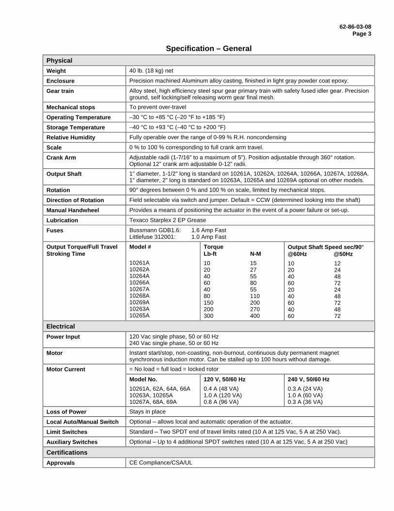
Specification – General
Physical
Weight 40 lb. (18 kg) net
Enclosure Precision machined Aluminum alloy casting, finished in light gray powder coat epoxy.
Gear train Alloy steel, high efficiency steel spur gear primary train with safety fused idler gear. Precisionground, self locking/self releasing worm gear final mesh.
Mechanical stops To prevent over-travel
Operating Temperature –30 °C to +85 °C (–20 °F to +185 °F)
Storage Temperature –40 °C to +93 °C (–40 °C to +200 °F)
Relative Humidity Fully operable over the range of 0-99 % R.H. noncondensing
Scale 0 % to 100 % corresponding to full crank arm travel.
Crank Arm Adjustable radii (1-7/16" to a maximum of 5"). Position adjustable through 360° rotation.Optional 12” crank arm adjustable 0-12” radii.
Output Shaft 1" diameter, 1-1/2" long is standard on 10261A, 10262A, 10264A, 10266A, 10267A, 10268A.1" diameter, 2" long is standard on 10263A, 10265A and 10269A optional on other models.
Rotation 90° degrees between 0 % and 100 % on scale, limited by mechanical stops.
Direction of Rotation Field selectable via switch and jumper. Default = CCW (determined looking into the shaft)
Manual Handwheel Provides a means of positioning the actuator in the event of a power failure or set-up.
Lubrication Texaco Starplex 2 EP Grease
Fuses Bussmann GDB1.6: 1.6 Amp FastLittlefuse 312001: 1.0 Amp Fast
Output Torque/Full TravelStroking Time
Model #
10261A10262A10264A10266A10267A10268A10269A10263A10265A
TorqueLb-ft N-M
10 1520 2740 5560 8040 5580 110150 200200 270300 400
Output Shaft Speed sec/90°@60Hz @50Hz
10 1220 2440 4860 7220 2440 4860 7240 4860 72
Electrical
Power Input 120 Vac single phase, 50 or 60 Hz240 Vac single phase, 50 or 60 Hz
Motor Instant start/stop, non-coasting, non-burnout, continuous duty permanent magnetsynchronous induction motor. Can be stalled up to 100 hours without damage.
Motor Current = No load = full load = locked rotor
Model No.
10261A, 62A, 64A, 66A10263A, 10265A10267A, 68A, 69A
120 V, 50/60 Hz
0.4 A (48 VA)1.0 A (120 VA)0.8 A (96 VA)
240 V, 50/60 Hz
0.3 A (24 VA)1.0 A (60 VA)0.3 A (36 VA)
Loss of Power Stays in place
Local Auto/Manual Switch Optional – allows local and automatic operation of the actuator.
Limit Switches Standard – Two SPDT end of travel limits rated (10 A at 125 Vac, 5 A at 250 Vac).
Auxiliary Switches Optional – Up to 4 additional SPDT switches rated (10 A at 125 Vac, 5 A at 250 Vac)
Certifications
Approvals CE Compliance/CSA/UL
62-86-03-10Page 4
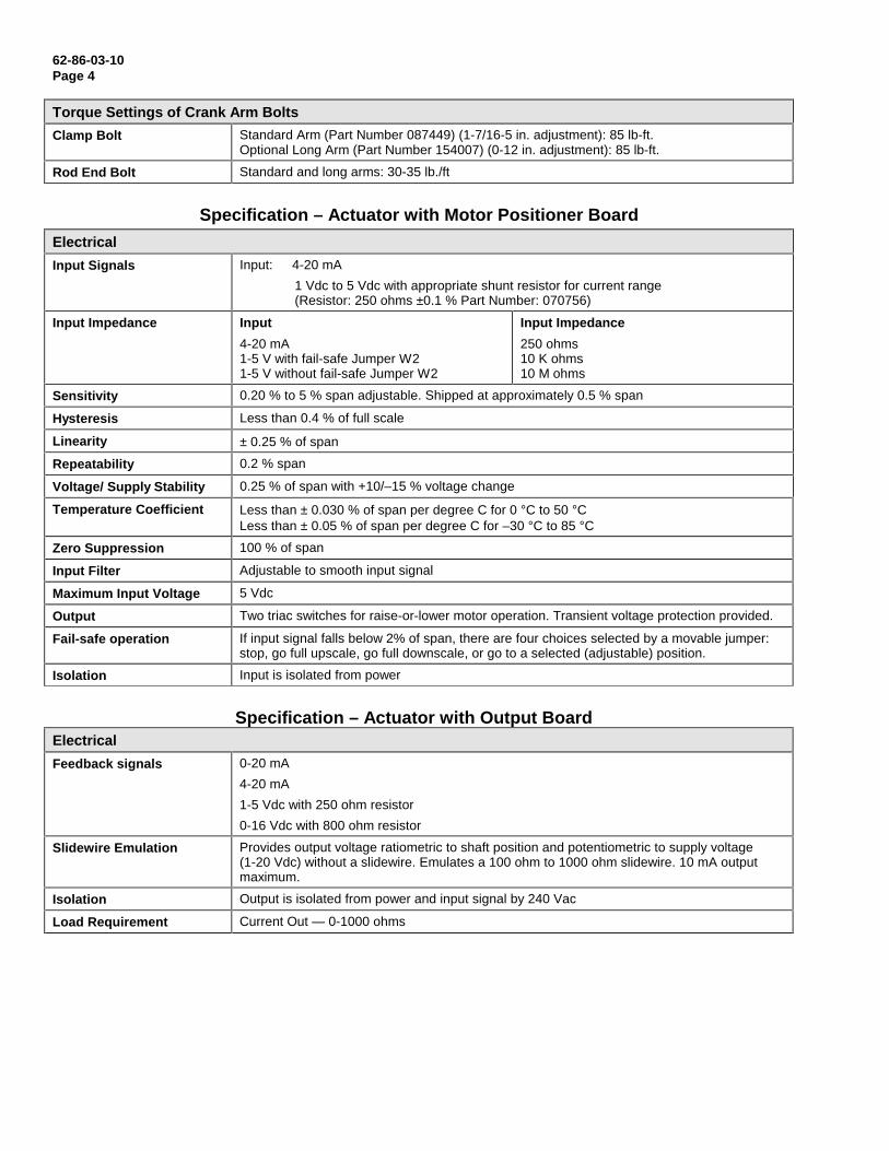
Torque Settings of Crank Arm Bolts
Clamp Bolt Standard Arm (Part Number 087449) (1-7/16-5 in. adjustment): 85 lb-ft.Optional Long Arm (Part Number 154007) (0-12 in. adjustment): 85 lb-ft.
Rod End Bolt Standard and long arms: 30-35 lb./ft
Specification – Actuator with Motor Positioner Board
Electrical
Input Signals Input: 4-20 mA
1 Vdc to 5 Vdc with appropriate shunt resistor for current range(Resistor: 250 ohms ±0.1 % Part Number: 070756)
Input Impedance Input
4-20 mA1-5 V with fail-safe Jumper W21-5 V without fail-safe Jumper W2
Input Impedance
250 ohms10 K ohms10 M ohms
Sensitivity 0.20 % to 5 % span adjustable. Shipped at approximately 0.5 % span
Hysteresis Less than 0.4 % of full scale
Linearity ± 0.25 % of span
Repeatability 0.2 % span
Voltage/ Supply Stability 0.25 % of span with +10/–15 % voltage change
Temperature Coefficient Less than ± 0.030 % of span per degree C for 0 °C to 50 °CLess than ± 0.05 % of span per degree C for –30 °C to 85 °C
Zero Suppression 100 % of span
Input Filter Adjustable to smooth input signal
Maximum Input Voltage 5 Vdc
Output Two triac switches for raise-or-lower motor operation. Transient voltage protection provided.
Fail-safe operation If input signal falls below 2% of span, there are four choices selected by a movable jumper:stop, go full upscale, go full downscale, or go to a selected (adjustable) position.
Isolation Input is isolated from power
Specification – Actuator with Output BoardElectrical
Feedback signals 0-20 mA
4-20 mA
1-5 Vdc with 250 ohm resistor
0-16 Vdc with 800 ohm resistor
Slidewire Emulation Provides output voltage ratiometric to shaft position and potentiometric to supply voltage(1-20 Vdc) without a slidewire. Emulates a 100 ohm to 1000 ohm slidewire. 10 mA outputmaximum.
Isolation Output is isolated from power and input signal by 240 Vac
Load Requirement Current Out — 0-1000 ohms
62-86-03-08Page 5
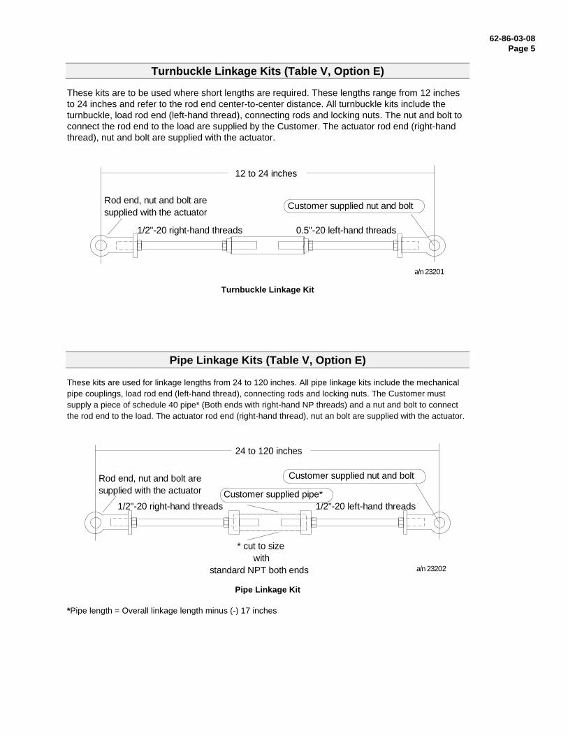
Turnbuckle Linkage Kits (Table V, Option E)
These kits are to be used where short lengths are required. These lengths range from 12 inchesto 24 inches and refer to the rod end center-to-center distance. All turnbuckle kits include theturnbuckle, load rod end (left-hand thread), connecting rods and locking nuts. The nut and bolt toconnect the rod end to the load are supplied by the Customer. The actuator rod end (right-handthread), nut and bolt are supplied with the actuator.
Rod end, nut and bolt aresupplied with the actuator
1/2"-20 right-hand threads 0.5"-20 left-hand threads
Customer supplied nut and bolt
12 to 24 inches
a/n 23201
Turnbuckle Linkage Kit
Pipe Linkage Kits (Table V, Option E)
These kits are used for linkage lengths from 24 to 120 inches. All pipe linkage kits include the mechanicalpipe couplings, load rod end (left-hand thread), connecting rods and locking nuts. The Customer mustsupply a piece of schedule 40 pipe* (Both ends with right-hand NP threads) and a nut and bolt to connectthe rod end to the load. The actuator rod end (right-hand thread), nut an bolt are supplied with the actuator.
Rod end, nut and bolt aresupplied with the actuator
1/2"-20 right-hand threads 1/2"-20 left-hand threads
Customer supplied nut and bolt
24 to 120 inches
Customer supplied pipe*
* cut to sizewith
standard NPT both ends a/n 23202
Pipe Linkage Kit
*Pipe length = Overall linkage length minus (-) 17 inches
62-86-03-10Page 6
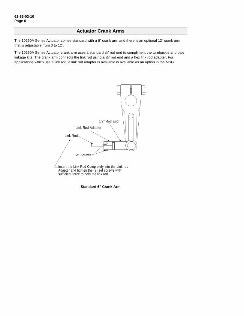
Actuator Crank Arms
The 10260A Series Actuator comes standard with a 6” crank arm and there is an optional 12” crank armthat is adjustable from 0 to 12”.
The 10260A Series Actuator crank arm uses a standard ½” rod end to compliment the turnbuckle and pipelinkage kits. The crank arm connects the link rod using a ½” rod end and a hex link rod adapter. Forapplications which use a link rod, a link rod adapter is available is available as an option in the MSG.
1/2" Rod End
Link Rod Adapter
Link Rod
Set Screws
Insert the Link Rod Completely into the Link rodAdapter and tighten the (2) set screws withsufficient force to hold the link rod.
Standard 6” Crank Arm
62-86-03-08Page 7
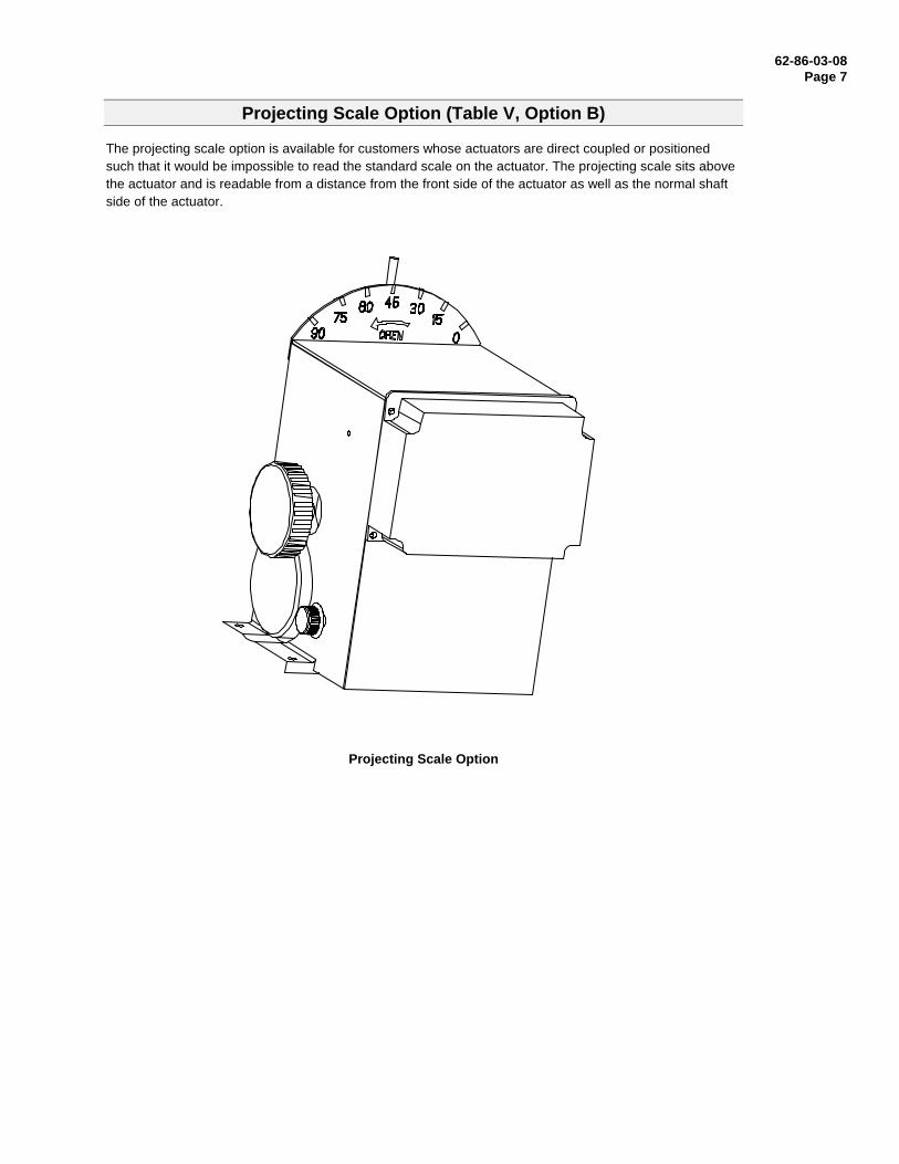
Projecting Scale Option (Table V, Option B)
The projecting scale option is available for customers whose actuators are direct coupled or positionedsuch that it would be impossible to read the standard scale on the actuator. The projecting scale sits abovethe actuator and is readable from a distance from the front side of the actuator as well as the normal shaftside of the actuator.
Projecting Scale Option
62-86-03-10Page 8
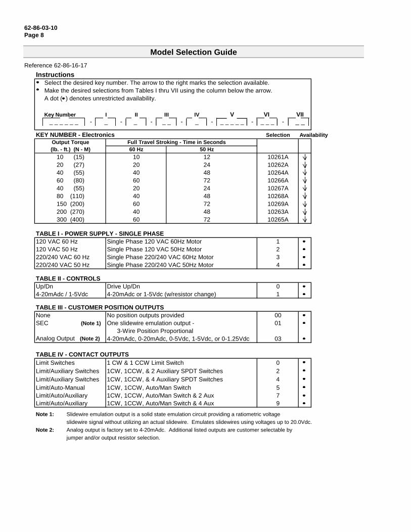
Model Selection Guide
Reference 62-86-16-17
InstructionsSelect the desired key number. The arrow to the right marks the selection available.Make the desired selections from Tables I thru VII using the column below the arrow.A dot ( ) denotes unrestricted availability.
Key Number I II III IV V VI VII_ _ _ _ _ _ - _ - _ - _ _ - _ - _ _ _ _ _ - _ _ _ - _ _
KEY NUMBER - Electronics Selection AvailabilityOutput Torque Full Travel Stroking - Time in Seconds(lb. - ft.) (N - M) 60 Hz 50 Hz
10 (15) 10 12 10261A20 (27) 20 24 10262A40 (55) 40 48 10264A60 (80) 60 72 10266A40 (55) 20 24 10267A80 (110) 40 48 10268A150 (200) 60 72 10269A200 (270) 40 48 10263A300 (400) 60 72 10265A
TABLE I - POWER SUPPLY - SINGLE PHASE120 VAC 60 Hz Single Phase 120 VAC 60Hz Motor 1120 VAC 50 Hz Single Phase 120 VAC 50Hz Motor 2220/240 VAC 60 Hz Single Phase 220/240 VAC 60Hz Motor 3220/240 VAC 50 Hz Single Phase 220/240 VAC 50Hz Motor 4
TABLE II - CONTROLSUp/Dn Drive Up/Dn 04-20mAdc / 1-5Vdc 4-20mAdc or 1-5Vdc (w/resistor change) 1
TABLE III - CUSTOMER POSITION OUTPUTSNone No position outputs provided 00SEC (Note 1) One slidewire emulation output - 01
3-Wire Position ProportionalAnalog Output (Note 2) 4-20mAdc, 0-20mAdc, 0-5Vdc, 1-5Vdc, or 0-1.25Vdc 03
TABLE IV - CONTACT OUTPUTSLimit Switches 1 CW & 1 CCW Limit Switch 0Limit/Auxiliary Switches 1CW, 1CCW, & 2 Auxiliary SPDT Switches 2Limit/Auxiliary Switches 1CW, 1CCW, & 4 Auxiliary SPDT Switches 4Limit/Auto-Manual 1CW, 1CCW, Auto/Man Switch 5Limit/Auto/Auxiliary 1CW, 1CCW, Auto/Man Switch & 2 Aux 7Limit/Auto/Auxiliary 1CW, 1CCW, Auto/Man Switch & 4 Aux 9
Note 1: Slidewire emulation output is a solid state emulation circuit providing a ratiometric voltage
slidewire signal without utilizing an actual slidewire. Emulates slidewires using voltages up to 20.0Vdc.
Note 2: Analog output is factory set to 4-20mAdc. Additional listed outputs are customer selectable by
jumper and/or output resistor selection.
62-86-03-08Page 9
1026_ _
1A, 2A, 4A, 6A7A, 8A, 9A, 3A
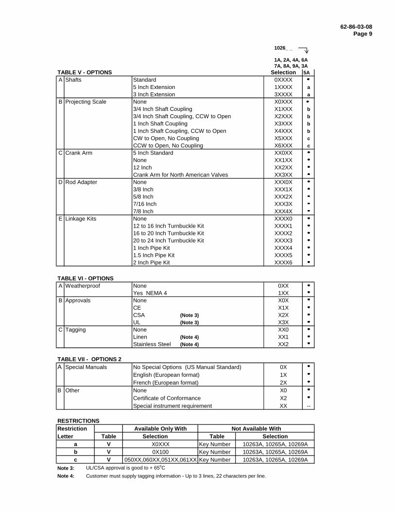
TABLE V - OPTIONS Selection 5AA Shafts Standard 0XXXX
5 Inch Extension 1XXXX a3 Inch Extension 3XXXX a
B Projecting Scale None X0XXX3/4 Inch Shaft Coupling X1XXX b3/4 Inch Shaft Coupling, CCW to Open X2XXX b1 Inch Shaft Coupling X3XXX b1 Inch Shaft Coupling, CCW to Open X4XXX bCW to Open, No Coupling X5XXX cCCW to Open, No Coupling X6XXX c
C Crank Arm 5 Inch Standard XX0XXNone XX1XX12 Inch XX2XXCrank Arm for North American Valves XX3XX
D Rod Adapter None XXX0X3/8 Inch XXX1X5/8 Inch XXX2X7/16 Inch XXX3X7/8 Inch XXX4X
E Linkage Kits None XXXX012 to 16 Inch Turnbuckle Kit XXXX116 to 20 Inch Turnbuckle Kit XXXX220 to 24 Inch Turnbuckle Kit XXXX31 Inch Pipe Kit XXXX41.5 Inch Pipe Kit XXXX52 Inch Pipe Kit XXXX6
TABLE VI - OPTIONSA Weatherproof None 0XX
Yes NEMA 4 1XXB Approvals None X0X
CE X1XCSA (Note 3) X2XUL (Note 3) X3X
C Tagging None XX0Linen (Note 4) XX1Stainless Steel (Note 4) XX2
TABLE VII - OPTIONS 2A Special Manuals No Special Options (US Manual Standard) 0X
English (European format) 1XFrench (European format) 2X
B Other None X0Certificate of Conformance X2Special instrument requirement XX --
RESTRICTIONSRestriction Available Only With Not Available WithLetter Table Selection Table Selection
a V X0XXX Key Number 10263A, 10265A, 10269Ab V 0X100 Key Number 10263A, 10265A, 10269Ac V 050XX,060XX,051XX,061XX Key Number 10263A, 10265A, 10269A
Note 3: UL/CSA approval is good to + 65oC
Note 4: Customer must supply tagging information - Up to 3 lines, 22 characters per line.
62-86-03-10P
age 10
5.500 [139.70]
9.812 [249.22]
8.938 [227.03]
4.469 [113.51]
1.625 [41.28]
DIA3.375 [85.73]
11.125 [282.58] MIN FOR COVER REMOVEL
FULL CRANKTRAVEL 90°
1/2-20UNF-2B X 1.239(31.47)DEEP THREAD
1/2-13UNC-2B X 2 LONGGRADE 5 OR BETTER BOLT
4.5001.938(49.21) (114.3)
TAPPED HOLE FOR1" CONDUIT.
ACCESS COVER TOTERMINAL BOARD
2.500(63.50)
ACCESS COVER
4.000
4.718
5/16-24 UNF-2Bx.500 (12.7) DP.TYP. 4 TAPPED HOLES EACH SIDE
1.000 DIA. (25.4)SHAFT
0.688(17.46)
HANDWHEEL
MOTOR
(REF.)
(REF.)
7.688
3.844(195.26)
(97.63)
MOTOR.281(7.14) DIA.HOLE(4)
ACCESS COVER TOSPUR GEARING
(121.43)
(101.6)
HANDWHEEL
10269 SERIES HAS AKNURLED OUTPUT SHAFT
SPACER
0.437 [11.10]
0.375
0.596 [15.15]
2.718 [69.04]
1.375 [34.93]
2.125 [53.98]
5.375 [136.53]
2.031 [51.59]
0.437 [11.10]
0.596 [15.15]
5.000
2.125
8.625
8.187 [207.95]
10.125 [257.18]
1.500 [38.10]
0.687 [17.45]
11.062 [280.97][127.00] MAX
53.98
[219.08]
[9.52]
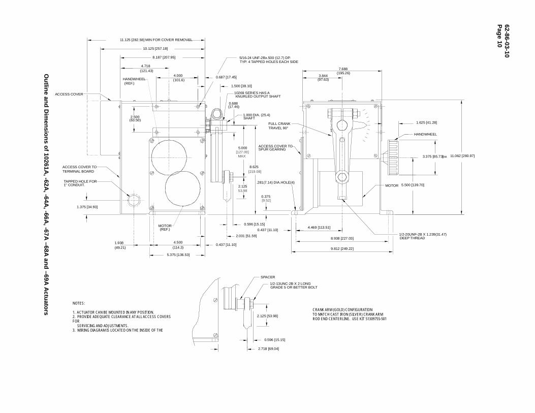
NOTES:
1. ACTUATOR CAN BE MOUNTED IN ANY POSITION.2. PROVIDE ADEQUATE CLEARANCE AT ALL ACCESS COVERS FOR SERVICING AND ADJUSTMENTS.3. WIRING DIAGRAM IS LOCATED ON THE INSIDE OF THE
CRANK ARM (GOLD) CONFIGURATIONTO MATCH CAST IRON (SILVER) CRANK ARMROD END CENTERLINE. USE KIT 51309755-501
Ou
tline an
d D
imen
sion
s of 10261A
, -62A, -64A
, -66A, -67A
–68A an
d –69A
Actu
ators
62-86-03-08P
age 11
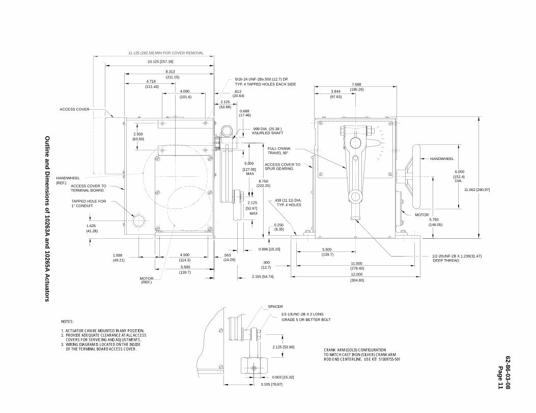
11.062 [280,97]
5.500(139.7)
4.5001.938(49.21) (114.3)
.563(14.29)
1.625(41.28)
TAPPED HOLE FOR1" CONDUIT.
ACCESS COVER TOTERMINAL BOARD
2.500(63.50)
ACCESS COVER
8.313
4.000
4.718
.813(20.64)
5/16-24 UNF-2Bx.500 (12.7) DP.TYP. 4 TAPPED HOLES EACH SIDE
.999 DIA. (25.38 )KNURLED SHAFT
0.688(17.46)
2.125(53.98)
HANDWHEEL
MOTOR
(REF.)
(REF.)
7.688
3.844 (195.26)
(97.63)
6.000(152.4) DIA.
5.750(146.05)
MOTOR
12.000
(304.80)
11.000
5.500
0.250
.438 (11.11) DIA.TYP. 4 HOLES
.500(12.7)
ACCESS COVER TOSPUR GEARING
(211.15)
(121.43)
(101.6)
(6.35)
(139.7)
(279.40)
HANDWHEEL
8.750(222.25)
3.105 [78,87]
SPACER
10.125 [257.18]
FULL CRANKTRAVEL 90°
1/2-20UNF-2B X 1.239(31.47)DEEP THREAD
MOTOR
2.125
[53.97]MAX
5.000
[127.00]MAX
2.155 [54.74]
0.596 [15.15]
1/2-13UNC-2B X 2 LONG
GRADE 5 OR BETTER BOLT
0.603 [15.32]
2.125 [53.98]
11.125 (282.58] MIN FOR COVER REMOVAL
CRANK ARM (GOLD) CONFIGURATIONTO MATCH CAST IRON (SILVER) CRANK ARMROD END CENTERLINE. USE KIT 51309755-501
NOTES:
1. ACTUATOR CAN BE MOUNTED IN ANY POSITION.2. PROVIDE ADEQUATE CLEARANCE AT ALL ACCESS COVERS FOR SERVICING AND ADJUSTMENTS.3. WIRING DIAGRAM IS LOCATED ON THE INSIDE OF THE TERMINAL BOARD ACCESS COVER.
Ou
tline an
d D
imen
sion
s of 10263A
and
10265A A
ctuato
rs
62-86-03-10Page 12
WARRANTY/REMEDY
Honeywell warrants goods of its manufacture as being free of defective materials and faulty workmanship.Contact your local sales office for warranty information. If warranted goods are returned to Honeywell duringthe period of coverage, Honeywell will repair or replace without charge those items it finds defective. Theforegoing is Buyer’s sole remedy and is in lieu of all other warranties, expressed or implied, includingthose of merchantability and fitness for a particular purpose. Specifications may change withoutnotice. The information we supply is believed to be accurate and reliable as of this printing. However, weassume no responsibility for its use.
While we provide application assistance personally, through our literature and the Honeywell web site, it isup to the customer to determine the suitability of the product in the application.
For more information, contact Honeywell sales at (800) 343-0228.
Distributor :
Sensing and ControlHoneywell11 West Spring StreetFreeport, IL 61032
62-86-03-10 1000 Printed in USA www.honeywell.com/sensing