Embed Size (px)
DESCRIPTION
PV valves
Citation preview

BAY Valves ApS [email protected] Tel.: +45 7022 1892 Fax.: +45 7014 1892 Valve order No.: 90011-10328 Page 1 of 33
BAY Valves ApS – Falstervej 10G - 5800 Nyborg - Denmark
Cargo tank Safety valves & Flame protection equipment
BAY Valves ApS, are pleased to have delivered the latest generation state of the art equipment according to the specification as follows. For easy reference to the mandatory Rules and Regulations that have been used to determine the specific design and size of equipment, please look at the following pages where the applicable ones have been marked. Exact calculations are likewise in-cooperated in this document where appropriate. Should you have any questions, or require further information related to our delivery or any other cargo tank ventilation issue, please do not hesitate to contact the undersigned or our office, and we will be pleased to assist you. Best regards, BAY Valves ApS
MAINTENANCE - MANUAL NO.:
90011-10328
Project: VESSEL CLASS A
Vessel: BUNGA ANGSANA
Owner: MISC BERHAD
IMO type: CHEMICAL TANKER IMO 2
Size: 38000 DWT
Valve Production No.: 10328
Certificate No.: NK 1279 CP 1300050
DNV / MED-B-7842

BAY Valves ApS [email protected] Tel.: +45 7022 1892 Fax.: +45 7014 1892 Valve order No.: 90011-10328 Page 2 of 33
BAY Valves ApS – Falstervej 10G - 5800 Nyborg - Denmark
Index Index ............................................................................................................................................................................................. 2 Rules & Regulations ................................................................................................................................................................... 4 System design .............................................................................................................................................................................. 5
Questionnaire ..................................................................................................................................................................... 5 Piping lay-out .................................................................................................................................................................. 18 Pressure drop calculation .............................................................................................................................................. 18 Test report ....................................................................................................................................................................... 18
Valve characteristic .................................................................................................................................................................. 18 Valve description ............................................................................................................................................................ 18 Gas freeing Covers: ........................................................................................................................................................... 8 Test bench - portable: ....................................................................................................................................................... 9
Valve characteristic .................................................................................................................................................................. 11 Equipment sizing ................................................................................................................................................................ 11
Calculation DN 100 ....................................................................................................................................................... 11 Criteria: finding min pipe size at given loading rate ...................................................................................................... 11
Drawings: ......................................................................................................................................................................... 12 Documentation & Certificates .............................................................................................................................................. 17 Product evaluation according to ISO 15364 ....................................................................................................................... 19
Quick guide. .................................................................................................................................................................... 19 ISO ordering information.................................................................................................................................................. 20
Installation limitations ................................................................................................................................................... 21 Installation instructions ................................................................................................................................................. 22 Operating instructions ................................................................................................................................................... 22 Inspections prior to loading / Un-loading! ................................................................................................................ 22 Freezing conditions ........................................................................................................................................................ 22 Check-lift ......................................................................................................................................................................... 22
Pressure side valve ................................................................................................................................................ 22 Vacuum side valve ................................................................................................................................................ 22
Maintenance ............................................................................................................................................................................. 23 Corrosion protection system ............................................................................................................................................. 23 Pressure side valve .............................................................................................................................................................. 24
Drawing 70001 ................................................................................................................................................................ 24 Description ...................................................................................................................................................................... 24 Item list ............................................................................................................................................................................ 25 Actions ............................................................................................................................................................................. 25
Inspections ............................................................................................................................................................. 25 Cleaning .................................................................................................................................................................. 25 Settings .................................................................................................................................................................... 25 Adjusting the setting ............................................................................................................................................. 25
Replacement of parts ..................................................................................................................................................... 26 Guide ....................................................................................................................................................................... 26 Dismantling & reassembly ................................................................................................................................... 26
Vacuum side valve & Flame arrester ............................................................................................................................... 26 Drawing 70003 ................................................................................................................................................................ 26 Description ...................................................................................................................................................................... 27 Item list ............................................................................................................................................................................ 27 Actions ............................................................................................................................................................................. 27
Check-lift ................................................................................................................................................................ 27 Inspections ............................................................................................................................................................. 27 Cleaning .................................................................................................................................................................. 27 Settings .................................................................................................................................................................... 27

BAY Valves ApS [email protected] Tel.: +45 7022 1892 Fax.: +45 7014 1892 Valve order No.: 90011-10328 Page 3 of 33
BAY Valves ApS – Falstervej 10G - 5800 Nyborg - Denmark
Replacement of parts ..................................................................................................................................................... 28 Guide ....................................................................................................................................................................... 28 Dismantling & reassembly ................................................................................................................................... 28
Gas freeing unit ................................................................................................................................................................... 28 Drawing 70005 ................................................................................................................................................................ 28 Description ...................................................................................................................................................................... 28 Item list ............................................................................................................................................................................ 28 Actions ............................................................................................................................................................................. 29
Inspections ............................................................................................................................................................. 29 Cleaning .................................................................................................................................................................. 29
Replacement of parts ..................................................................................................................................................... 29 Guide ....................................................................................................................................................................... 29 Dismantling & reassembly ................................................................................................................................... 29
Valve housing ...................................................................................................................................................................... 30 Drawing 70002 ................................................................................................................................................................ 30
Marking ..................................................................................................................................................................................... 31 Ordering spare-parts – just return this page ....................................................................................................................... 32 Contact ...................................................................................................................................................................................... 33

BAY Valves ApS [email protected] Tel.: +45 7022 1892 Fax.: +45 7014 1892 Valve order No.: 90011-10328 Page 4 of 33
BAY Valves ApS – Falstervej 10G - 5800 Nyborg - Denmark
Rules & Regulations 1.1 System Design.
SOLAS 74 chapter II-2 REG 59 Venting, purging, gas-freeing and ventilation.
IMO MSC/CIRC 731 Revised factors to be taken into consideration when designing cargo tank venting and gas-freeing arrangements.
USCG CFR 46 part 39 –Vapour control system. ISO 15364:2000
Ships and marine technology – Pressure/vacuum valves for cargo tanks.
ADNR 2003 Transport of Hazardous Material / Dangerous Goods on the river Rhein.
1.2 Test Standards
IMO MSC/CIRC 677 Revised standards for the design, testing and locating of Devices to prevent the Passage of Flames into cargo tanks in tankers.
IMO MSC/CIRC 1009 Amendments to the revised standards for the design, testing and locating of Devices to prevent the Passage of Flames into cargo tanks in tankers.
CEN European Standard EN 12874 Flame arresters – Performance requirements, test methods and limits for use.

BAY Valves ApS [email protected] Tel.: +45 7022 1892 Fax.: +45 7014 1892 Valve order No.: 90011-10328 Page 5 of 33
BAY Valves ApS – Falstervej 10G - 5800 Nyborg - Denmark
System design Questionnaire According to SOLAS 74 II Reg. 59 a system for cargo tank ventilation can be either a common or an individual one, which in both cases has to be protected by a Device to prevent the passage of flame as specified in IMO MSC/Circ 677/1009. A common system consists of a branch line from each cargo or slop tank connected to a common venting line. An individual system is equipped with approved equipment on each tank in order to secure full flow capacity, breathing capabilities and full cargo segregation. The system in question has been designed based on the following characteristic: INFORMED ESTIMATE INFORMED ESTIMATE IMO Designation IMO II Cargo tanks 18 Cargo Gas-group IIB Slop tanks 2 MESG 0,65 Other tanks USCG VCS YES Gas-freeing covers 20 Common Gas freeing blower IGS Individual YES Setting – pressure 2000 mm wg Cargo Segregation ALL Setting Vacuum - 350 mm wg Loading rate 650 m3/h Material AISI 316 Un-loading rate 550 m3/h Flange JIS 5K Please feel free to return this page only, which will be identified by the manual No. listed at the top of the page. For corrections or comments just mark with- or in writing in the text box below. IMO Designation: I II III Cargo segregation: Gas Group: IIA IIB IIC Loading rate: MESG: 0.90 0,65 0,50 Un-loading rate: Setting Pressure: Cargo Density: Setting Vacuum: USCG VCS: Yes/No Flange standard: Gas freeing blower: N m3/h Material: Please change accordingly: Date: Name: Company:
Comments:

BAY Valves ApS [email protected] Tel.: +45 7022 1892 Fax.: +45 7014 1892 Valve order No.: 90011-10328 Page 6 of 33
BAY Valves ApS – Falstervej 10G - 5800 Nyborg - Denmark
Application: Cargo tanks
Units: 18 Size: 100 Flange standard: JIS 5K (To be confirmed) Material-Housing: Stainless steel AISI 316 Material-Inner parts: Stainless steel AISI 316 Setting – Pressure: 2000 mm wg Setting – Vacuum: - 350 mm wg Loading Rate: 650 m3/h Capacity – SOLAS: 853 m3/h Capacity – VECS: 1269 Nm3/h Un-loading rate: 550 m3/h Vacuum Capacity: 850 Nm3/h @ 700 mm WG Drawing: 90001 Flow curve -pressure 90001-1202-100-020 Flow curve- vacuum 90001-1202-100-002 Features: High velocity valve, non-hammering
Non-oscillating (frequency less than 0,5 hz / ISO 15364:2007) Controlled blow-down, securing instant pressure drop to safety level 30% below setting in order to allow loading at a high capacity and at the same time avoiding a boil-off of cargo.
Test standard: IMO MSC/Circ 677/1009/ ISO 15364 & EN 12874 High-end features: Adjustable setting – Integrated gas freeing cover. Industry’s
highest constant net clearance between moving parts and valve housing – Suitable for freezing, sticking and crystallizing cargo. Exchangeable wear parts. Upgrading on-site to higher gas-groups.

BAY Valves ApS [email protected] Tel.: +45 7022 1892 Fax.: +45 7014 1892 Valve order No.: 90011-10328 Page 7 of 33
BAY Valves ApS – Falstervej 10G - 5800 Nyborg - Denmark
Application: Slop tanks
Units: 2 Size: 65 Flange standard: JIS 5K (To be confirmed) Material-Housing: Stainless steel AISI 316 Material-Inner parts: Stainless steel AISI 316 Setting – Pressure: 2000 mm wg Setting – Vacuum: - 350 mm wg Loading Rate: 180 m3/h Capacity – SOLAS: 237 Nm3/h Capacity – VECS: 352 Nm3/h Un-loading rate: 200 m3/h Vacuum Capacity: 400 m3/h @ 700 mm WG Drawing: 90001 Flow curve -pressure 90001-1202-065-020 Flow curve- vacuum 90001-1202-065-002 Features: High velocity valve, non-hammering
Non-oscillating (frequency less than 0,5 hz / ISO 15364:2007) Controlled blow-down, securing instant pressure drop to safety level 30% below setting in order to allow loading at a high capacity and at the same time avoiding a boil-off of cargo.
Test standard: IMO MSC/Circ 677/1009/ ISO 15364 & EN 12874 High-end features: Adjustable setting – Integrated gas freeing cover. Industry’s
highest constant net clearance between moving parts and valve housing – Suitable for freezing, sticking and crystallizing cargo. Exchangeable wear parts. Upgrading on-site to higher gas-groups.

BAY Valves ApS [email protected] Tel.: +45 7022 1892 Fax.: +45 7014 1892 Valve order No.: 90011-10328 Page 8 of 33
BAY Valves ApS – Falstervej 10G - 5800 Nyborg - Denmark
Gas freeing Covers:
Gas freeing covers approved according to IMO MSC/Circ 677.
Approved by leading Classification Societies and EC Notified bodies according to MED 96/98 and later amendments.
Application: Cargo and Slop tanks
Units: 18 / 2 Size: 100 / 65 Flange standard: Integrated in the High velocity valve Material-Housing: Stainless steel AISI 316 Material-Inner parts: Stainless steel AISI 316 Gas freeing rate - Estimated: 1500 Nm3/h Inert gas blower capacity Nominal per tank 500 Nm3/h gas freeing 3 tanks simultaneous Lowest per tank: 150 Nm3/h in order to secure a minimum gas velocity of 20 m/s Features: Safe opening with a bolted cover. An industry high capacity for
reduced pressure drop, securing a minimum gas velocity of 20 m/s.
NOTE! The blower capacity is estimated to 1500 m3/h. if 3 tanks are being supplied simultaneously the nominal rate per tank is 500 m3/h. The minimum rate for this size of gas freeing units is 150 m3/h – A lower rate does not secure a minimum efflux velocity of 20 m/s. If the blower capacity is lower than 450 m3/h less tanks e.g. 2 can be gas freed at the same time, alternatively a smaller flame screen unit can be used – Please state capacity of blower as well as requirement to number of tanks used simultaneously.

BAY Valves ApS [email protected] Tel.: +45 7022 1892 Fax.: +45 7014 1892 Valve order No.: 90011-10328 Page 9 of 33
BAY Valves ApS – Falstervej 10G - 5800 Nyborg - Denmark
Test bench - portable:

BAY Valves ApS [email protected] Tel.: +45 7022 1892 Fax.: +45 7014 1892 Valve order No.: 90011-10328 Page 10 of 33
BAY Valves ApS – Falstervej 10G - 5800 Nyborg - Denmark

BAY Valves ApS [email protected] Tel.: +45 7022 1892 Fax.: +45 7014 1892 Valve order No.: 90011-10328 Page 11 of 33
BAY Valves ApS – Falstervej 10G - 5800 Nyborg - Denmark
Valve characteristic
Equipment sizing
Calculation DN 100 Criteria: finding min pipe size at given loading rate π 3,141592654
Loading rate Q Q = V x D2 x π/4 x 3600 s/h = 650,0 [m3/h] (given)
Gas evolution factor GEF = 1,25
Fouling factor FF = 1,05
Vapour density VD = 2,85 [kg/m3]
Air density AD = 1,29 [kg/m3]
Density factor DFDF = √¯(VD/AD) = 1,49
Venting Capacity VQ VQ = Q x GEF x FF x DF = 1268,1 [m3/h]
Velocity in pipe (max) Vmax = 40 [m/s]
Diameter of pipe: Dmin =1000mm/m √ ((VQ x 4)/ (π x V x 3600 s/h)) = 105,9 [mm] (minimum)
Actual diameter of valve/pipe, Dv = 100,0 [mm] (standard)
Actual velocity in pipe V = VQ x 4 / π x D2 x 3600 s/h = 44,8 [m/s] (Check)
The above states that the correct minimum pipe size given a loading rate of 650 m3/h is 105,9 mm in order for the gas velocity in the piping system to be equal to - or less than 40 m/s. In this specific case the velocity is 44,8 m/s with a DN 100 pipe.

BAY Valves ApS [email protected] Tel.: +45 7022 1892 Fax.: +45 7014 1892 Valve order No.: 90011-10328 Page 12 of 33
BAY Valves ApS – Falstervej 10G - 5800 Nyborg - Denmark
Drawings:
Description: High velocity valve with integrated gas freeing unit
Designation: Drawing No.: 90001
HI Jet ISO II 1202
May be supplied with flanged spool pieces / flange standard DIN pn 10 for reference only
A B C D Dc Dn E F G n d SIZE 415 260 115 185 145 65 190 275 215 4 18 65 510 320 145 200 160 80 230 340 265 8 18 80 635 400 180 220 180 100 290 425 335 8 18 100 790 500 225 250 210 125 360 525 410 8 18 125 950 600 270 285 240 150 435 635 500 8 22 150 1200 750 300 340 295 200 500 800 600 8 22 200 1300 900 400 395 350 250 600 1000 780 12 22 250 1500 1000 500 445 400 300 750 1200 900 12 22 300 1900 1200 600 565 515 400 1000 1500 1200 16 26 400
70001 Pressure side high velocity valve
70002 Valve housing
70003 Vacuum side weight loaded valve
70004 Vacuum side flame screen
70005 Gas freeing unit
Available in all material combinations e.g. from Cast iron to Duplex stainless steel. Approved according to IMO MSC / Circ 677/1009 implementing ISO 15364. Type examination according to MED 96/98 latest 2002/75 EC provided by Bureau Veritas under Cert. No. 19876/AO EC

BAY Valves ApS [email protected] Tel.: +45 7022 1892 Fax.: +45 7014 1892 Valve order No.: 90011-10328 Page 13 of 33
BAY Valves ApS – Falstervej 10G - 5800 Nyborg - Denmark
Document type: Document No.: Notified Body: Certificate No.: Flow diagram 90001-1202-100-020 DNV To be informed
PRESSURE SIDE – HIGH VELOCITY VALVE
Valve setting: Lowest setting: Valve capacity: Conditions: 20 Kpa 12 Kpa 1700 Nm3/h @ 20 Kpa Standard air 21°C / 1013 hPa
Applicable rules Valve data Data√ IMO MSC/Circ 677/1009 Name HI Jet ISO II√ ISO 15364 No. 1202 Signature / Stamp√ MED 96/98 Size 100√ SOLAS 74 Restrictions: Lenght [m] Bends [No]√ API 2000 DN > 100 No restrict. No restrict.√ API 520 DN 80 65 11
DN 80 70 0MESG 0,65

BAY Valves ApS [email protected] Tel.: +45 7022 1892 Fax.: +45 7014 1892 Valve order No.: 90011-10328 Page 14 of 33
BAY Valves ApS – Falstervej 10G - 5800 Nyborg - Denmark
Document type: Document No.: Notified Body: Certificate No.: Flow diagram 90001-1202-100-002 DNV To be informed
VACUUM SIDE VALVE
Valve setting: Lowest setting: Valve capacity: Conditions: -3,5 Kpa -3,5 Kpa 850 Nm3/h @ 7 Kpa Standard air 21°C / 1013 hPa
Applicable rules Valve data Data√ IMO MSC/Circ 677/1009 Name HI Jet ISO II√ ISO 15364 No. 1202 Signature / Stamp√ MED 96/98 Size 100√ SOLAS 74 Restrictions: Lenght [m] Bends [No]√ API 2000 DN > 65 na na√ API 520 DN 80 na na
DN 80 na naMESG 0,65
Document type: Document No.: Notified Body: Certificate No.:
0
1
2
3
4
5
6
7
8
0 100 200 300 400 500 600 700 800 900 FLOW [N m3/h]
VACUUM [Kpa]

BAY Valves ApS [email protected] Tel.: +45 7022 1892 Fax.: +45 7014 1892 Valve order No.: 90011-10328 Page 15 of 33
BAY Valves ApS – Falstervej 10G - 5800 Nyborg - Denmark
Flow diagram 90001-1202-65-020 DNV To be informed
PRESSURE SIDE – HIGH VELOCITY VALVE
Valve setting: Lowest setting: Valve capacity: Conditions: 20 Kpa 12 Kpa 550 Nm3/h @ 20 Kpa Standard air 21°C / 1013 hPa
Applicable rules Valve data Data√ IMO MSC/Circ 677/1009 Name HI Jet ISO II√ ISO 15364 No. 1202 Signature / Stamp√ MED 96/98 Size 65√ SOLAS 74 Restrictions: Lenght [m] Bends [No]√ API 2000 DN > 65 No restrict. No restrict.√ API 520 DN 50 65 11
DN 50 70 0MESG 0,65

BAY Valves ApS [email protected] Tel.: +45 7022 1892 Fax.: +45 7014 1892 Valve order No.: 90011-10328 Page 16 of 33
BAY Valves ApS – Falstervej 10G - 5800 Nyborg - Denmark
Document type: Document No.: Notified Body: Certificate No.: Flow diagram 90001-1202-065-002 DNV To be informed
VACUUM SIDE VALVE
Valve setting: Lowest setting: Valve capacity: Conditions: -3,5 Kpa -3,5 Kpa 400 Nm3/h @ 7 Kpa Standard air 21°C / 1013 hPa
Applicable rules Valve data Data√ IMO MSC/Circ 677/1009 Name HI Jet ISO II√ ISO 15364 No. 1202 Signature / Stamp√ MED 96/98 Size 65√ SOLAS 74 Restrictions: Lenght [m] Bends [No]√ API 2000 DN > 65 na na√ API 520 DN 80 na na
DN 80 na naMESG 0,65
0
1
2
3
4
5
6
7
8
0 50 100 150 200 250 300 350 400 FLOW [N m3/h]
VACUUM [Kpa]
BAY Valves ApS [email protected] Tel.: +45 7022 1892 Fax.: +45 7014 1892 Valve order No.: 90011-10328 Page 17 of 33
BAY Valves ApS – Falstervej 10G - 5800 Nyborg - Denmark
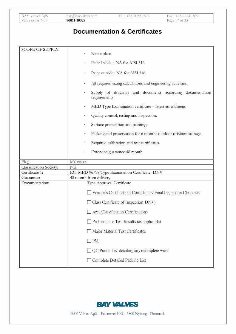
Documentation & Certificates SCOPE OF SUPPLY:
- Name plate.
- Paint Inside : NA for AISI 316
- Paint outside : NA for AISI 316
- All required sizing calculations and engineering activities.
- Supply of drawings and documents according documentation requirements.
- MED Type Examination certificate – latest amendment.
- Quality control, testing and inspection.
- Surface preparation and painting.
- Packing and preservation for 6 months outdoor offshore storage.
- Required calibration and test certificates.
- Extended guarantee 48 month
Flag: Malaysian Classification Society: NK Certificate 1: EC- MED 96/98 Type Examination Certificate -DNV Guarantee: 48 month from delivery Documentation: Type Approval Certificate
Vendor’s Certificate of Compliance/ Final Inspection Clearance
Class Certificate of Inspection (DNV)
Area Classification Certifications
Performance Test Results (as applicable)
Major Material Test Certificates
PMI
QC Punch List detailing any incomplete work
Complete Detailed Packing List
BAY Valves ApS [email protected] Tel.: +45 7022 1892 Fax.: +45 7014 1892 Valve order No.: 90011-10328 Page 18 of 33
BAY Valves ApS – Falstervej 10G - 5800 Nyborg - Denmark
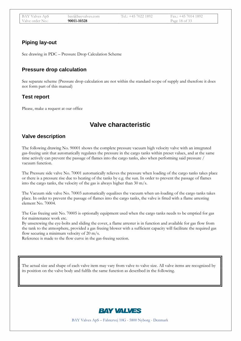
Piping lay-out See drawing in PDC – Pressure Drop Calculation Scheme
Pressure drop calculation See separate scheme (Pressure drop calculation are not within the standard scope of supply and therefore it does not form part of this manual)
Test report Please, make a request at our office
Valve characteristic Valve description The following drawing No. 90001 shows the complete pressure vacuum high velocity valve with an integrated gas-freeing unit that automatically regulates the pressure in the cargo tanks within preset values, and at the same time actively can prevent the passage of flames into the cargo tanks, also when performing said pressure / vacuum function. The Pressure side valve No. 70001 automatically relieves the pressure when loading of the cargo tanks takes place or there is a pressure rise due to heating of the tanks by e.g. the sun. In order to prevent the passage of flames into the cargo tanks, the velocity of the gas is always higher than 30 m/s. The Vacuum side valve No. 70003 automatically equalizes the vacuum when un-loading of the cargo tanks takes place. In order to prevent the passage of flames into the cargo tanks, the valve is fitted with a flame arresting element No. 70004. The Gas freeing unit No. 70005 is optionally equipment used when the cargo tanks needs to be emptied for gas for maintenance work etc. By unscrewing the eye-bolts and sliding the cover, a flame arrester is in function and available for gas flow from the tank to the atmosphere, provided a gas freeing blower with a sufficient capacity will facilitate the required gas flow securing a minimum velocity of 20 m/s. Reference is made to the flow curve in the gas-freeing section.
The actual size and shape of each valve item may vary from valve to valve size. All valve items are recognized by its position on the valve body and fulfils the same function as described in the following.
BAY Valves ApS [email protected] Tel.: +45 7022 1892 Fax.: +45 7014 1892 Valve order No.: 90011-10328 Page 19 of 33
BAY Valves ApS – Falstervej 10G - 5800 Nyborg - Denmark
Product evaluation according to ISO 15364 Quick guide. The standard specifies the minimum requirements for performance and testing of pressure-vacuum valves, with emphasis on selection of materials, internal finish and surface requirements. It further specifies design and in-service performance criteria, operational testing and maintenance requirements. The following is an extract of the international standard made in order to facilitate a platform on which the user of the venting system, on a qualified basis, can evaluate the suitability of the installed equipment. A more detailed review is available in the Product review document as referred to in the EC – MED 96/98 certificate, a document which actually forms part of said certificate.

BAY Valves ApS [email protected] Tel.: +45 7022 1892 Fax.: +45 7014 1892 Valve order No.: 90011-10328 Page 20 of 33
BAY Valves ApS – Falstervej 10G - 5800 Nyborg - Denmark
ISO ordering information Orders for devices under the specification of ISO 15364 shall include the following information, as applicable: Informed – design criteria Corrections Nominal pipe size Configuration of piping Pipe length Maximum gas density Maximum gas evolution factor Maximum experimental safe gap Set opening point – pressure Set opening point – vacuum Maximum overpressure surge allowed over the device at any flow rate
Minimum reseating pressure Maximum ambient air temperature Minimum ambient air temperature Materials of construction - Annex B Coating – Annex C Maximum gas flow in standard air Design pressure drop of piping system
Maximum tank pressure Maximum tank vacuum Maximum outer ice layer Maximum inner fouling layer Heating requirement Minimum velocity of the unimpeded gas jet above the valves outlet
Cargo temperature Maximum gas leakage rate NOTE The information provided shall include the specifications by reference to a recognized national or international standard on materials of construction for the following components: • housing and bolting. • discs, spindles, seats, springs, gaskets, seals, flame arresting components. If any of above mentioned information is in conflict with the present use, please return this page and we shall be pleased to assist you in a correctional step towards an improved functionality. Please change accordingly: Date / Name Title: Company:
Vessel name e-mail: Phone / Fax:

BAY Valves ApS [email protected] Tel.: +45 7022 1892 Fax.: +45 7014 1892 Valve order No.: 90011-10328 Page 21 of 33
BAY Valves ApS – Falstervej 10G - 5800 Nyborg - Denmark
Installation limitations PRODUCTION / ORDER NO See front
Specific limitations for this production
Nominal pipe size, configuration of piping, and pipe Length 30m/dn80 and 62m/dn65 respectively
Maximum considered gas density tank pressure limits. See PDC 10328 Lowest MESG. 0,65 Set opening points for pressure and vacuum 2000 / -350 mm wg Maximum pressure drop. See PDC 10328 Pressure drop at maximum flow See PDC 10328 Minimum reseating pressure 1000 mm wg Maximum and minimum ambient temperature NA Materials of construction AISI 316 Surface treatment and coating NA and maximum tank pressure. See PDC 10328 Maximum outer ice layer thickness. 20mm For high velocity vents: the minimum average velocity required 30 m/s for cross section of the valve's outlet to atmosphere.

BAY Valves ApS [email protected] Tel.: +45 7022 1892 Fax.: +45 7014 1892 Valve order No.: 90011-10328 Page 22 of 33
BAY Valves ApS – Falstervej 10G - 5800 Nyborg - Denmark
Installation instructions The device has to be installed vertically on a flange and pipe size matching the one on the valve. Please observe SOLAS 74 (2000) Part 2-II Reg. 59 for installation requirement relating to the vessel and other equipment. Please observe great care when installing the valves, that the top of the valve containing disc and magnet housing are not in any way bend or touched by crane wire etc. during transportation and final installation.
Operating instructions The device is a pressure and vacuum valve, which operates automatically once installed. For restrictions, please see the EC MED Type Examination Certificate.
Inspections prior to loading / Un-loading! Prior to loading and un-loading, the valve must always be check-lifted in order to verify - - unobstructed movement of the moving parts, and - that fouling conditions are minimized to establish safe operation and full capacity.
Freezing conditions When an end of line high velocity valve is covered with ice it cannot open within the preset values e.g. 2000 mm WG. Ice has to be removed by very carefully using a soft hammer or wooden stick on the top cover and moving disc until all ice has been removed - Then check that the valve and tank pressure is above 50% of the setting before operating the check lift carefully. Failure to comply with the above will render the valve function and guarantee void.
Check-lift
Pressure side valve Turn the check-lift handle 10039 drawing No. 70002 clock-wise app. 90 degrees, and watch the valve open. Check-lifting should be done on a regular basis in order to register the force needed for opening, if the valve does not move freely inspection is needed.
Vacuum side valve Push the valve open by use of the knob pos. 10033 drawing No. 70003 Check-lifting should be done on a regular basis in order to register the force needed for opening, if the valve does not move freely inspection is needed

BAY Valves ApS [email protected] Tel.: +45 7022 1892 Fax.: +45 7014 1892 Valve order No.: 90011-10328 Page 23 of 33
BAY Valves ApS – Falstervej 10G - 5800 Nyborg - Denmark
Maintenance In general, before any maintenance work is commenced, the pressure in the cargo tanks has to be lowered to the same pressure as when ullage measurements take place.
For safety reasons, use only tools approved for work in cargo tanks.
Corrosion protection system Please consult the paint manufacturer for maintenance of the paint system identified as: For Oil tankers
Hempel Hempadur 1540
For Chemical tankers
Hempel Hempadur 1550
Paint description LAYER NUMBER NAME THICKNESS COLOUR FIRST SECOND THIRD

BAY Valves ApS [email protected] Tel.: +45 7022 1892 Fax.: +45 7014 1892 Valve order No.: 90011-10328 Page 24 of 33
BAY Valves ApS – Falstervej 10G - 5800 Nyborg - Denmark
Pressure side valve
Drawing 70001
Description On drawing 70001 the pressure side valve is shown. The valve closes tight between the disc 10012 and the seat 10004, when the pressure in the tank rises due to loading or e.g. higher temperature, the valve will open and gas will be ejected between the two parts vertically, at never less than 30 m/s. When the pressure in the tank has been lowered about 30 -50% depending on the setting, the valve will close again.
BAY Valves ApS [email protected] Tel.: +45 7022 1892 Fax.: +45 7014 1892 Valve order No.: 90011-10328 Page 25 of 33
BAY Valves ApS – Falstervej 10G - 5800 Nyborg - Denmark
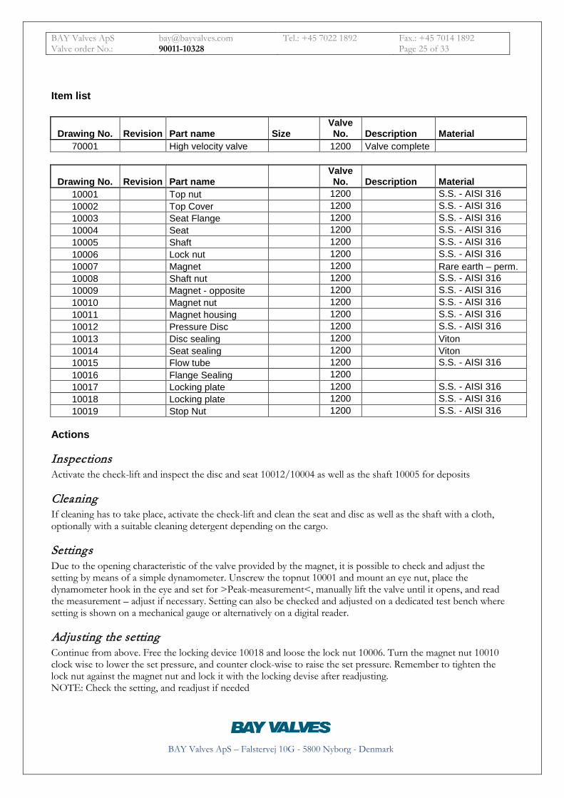
Item list
Drawing No. Revision Part name Size Valve No. Description Material
70001 High velocity valve 1200 Valve complete
Drawing No. Revision Part name Valve No. Description Material
10001 Top nut 1200 S.S. - AISI 316 10002 Top Cover 1200 S.S. - AISI 316 10003 Seat Flange 1200 S.S. - AISI 316 10004 Seat 1200 S.S. - AISI 316 10005 Shaft 1200 S.S. - AISI 316 10006 Lock nut 1200 S.S. - AISI 316 10007 Magnet 1200 Rare earth – perm. 10008 Shaft nut 1200 S.S. - AISI 316 10009 Magnet - opposite 1200 S.S. - AISI 316 10010 Magnet nut 1200 S.S. - AISI 316 10011 Magnet housing 1200 S.S. - AISI 316 10012 Pressure Disc 1200 S.S. - AISI 316 10013 Disc sealing 1200 Viton 10014 Seat sealing 1200 Viton 10015 Flow tube 1200 S.S. - AISI 316 10016 Flange Sealing 1200 10017 Locking plate 1200 S.S. - AISI 316 10018 Locking plate 1200 S.S. - AISI 316 10019 Stop Nut 1200 S.S. - AISI 316
Actions
Inspections Activate the check-lift and inspect the disc and seat 10012/10004 as well as the shaft 10005 for deposits
Cleaning If cleaning has to take place, activate the check-lift and clean the seat and disc as well as the shaft with a cloth, optionally with a suitable cleaning detergent depending on the cargo.
Settings Due to the opening characteristic of the valve provided by the magnet, it is possible to check and adjust the setting by means of a simple dynamometer. Unscrew the topnut 10001 and mount an eye nut, place the dynamometer hook in the eye and set for >Peak-measurement<, manually lift the valve until it opens, and read the measurement – adjust if necessary. Setting can also be checked and adjusted on a dedicated test bench where setting is shown on a mechanical gauge or alternatively on a digital reader.
Adjusting the setting Continue from above. Free the locking device 10018 and loose the lock nut 10006. Turn the magnet nut 10010 clock wise to lower the set pressure, and counter clock-wise to raise the set pressure. Remember to tighten the lock nut against the magnet nut and lock it with the locking devise after readjusting. NOTE: Check the setting, and readjust if needed

BAY Valves ApS [email protected] Tel.: +45 7022 1892 Fax.: +45 7014 1892 Valve order No.: 90011-10328 Page 26 of 33
BAY Valves ApS – Falstervej 10G - 5800 Nyborg - Denmark
Replacement of parts
Guide With each part delivered for replacement, a specific guide for dismantling, replacement and requirement to accuracy, e.g. lapping will be delivered.
Dismantling & reassembly Remove the topnut 10001 and cover 10002. Unscrew the shaft nut 10008, the shaft will then be lowered and will rest on the shaft guide 10048 in the valve body. Remove the magnet house No. 10011 by un screwing the entire house from the disc 10012. Loosen the lock nut 10006 and unscrew the magnet nut 10010 and the lock nut. The disc can now be pulled off the upper part of the flange 10003 which can then be removed by loosen the 4 bolts which holds the flange to the valve body. Reassembling is done in the opposite sequence.
Vacuum side valve & Flame arrester
Drawing 70003

BAY Valves ApS [email protected] Tel.: +45 7022 1892 Fax.: +45 7014 1892 Valve order No.: 90011-10328 Page 27 of 33
BAY Valves ApS – Falstervej 10G - 5800 Nyborg - Denmark
Description
Item list
Drawing No. Revision Part name Size Valve No. Description Material
70003 Vacuum valve 1200 70004 Flame screen 1200
Actions
Check-lift Push the valve open by use of the handle pos. 10033 drawing No. 70003 Check-lifting should be done on a regular basis in order to register the force needed for opening, if the valve does not move freely inspection is needed
Inspections On a regular basis e.g. once every six month depending on the cargo carried, or if the valve does not move freely, check the fouling indication pin pos. 10046 drawing No. 70002 for deposits. Alternatively lower the pressure in the tank to ullage level and remove the gas freeing unit – for description see section >Gas freeing unit<.
Cleaning After having removed the gas freeing unit, lift the valve with the check lift and clean the disc and seat with a cloth, alternatively use a suitable cleaning detergent depending on the cargo carried.
Settings The setting can only be changed by varying the weight of the disc. Please contact our office.
Drawing No. Revision Part name Size Valve No. Description Material
10021 Vacuum Disc 1200 S.S. - AISI 316 10022 Vacuum seat 1200 S.S. - AISI 316 10023 Vacuum Seat flange 1200 S.S. - AISI 316 10024 Vacuum housing 1200 S.S. - AISI 316 10025 Shaft Bushing 1200 Bronze 10026 Bushing Nut 1200 Bronze 10027 Flame Screen Bushing 1200 Bronze 10028 Flame Screen 1200 S.S. - AISI 316 10029 Flame Screen Guide 1200 S.S. - AISI 316 10030 Flame Screen Ring 1200 S.S. - AISI 316 10031 Flame Screen Cover 1200 S.S. - AISI 316 10032 Shaft 1200 S.S. - AISI 316 10033 Check lift handle 1200 Pom

BAY Valves ApS [email protected] Tel.: +45 7022 1892 Fax.: +45 7014 1892 Valve order No.: 90011-10328 Page 28 of 33
BAY Valves ApS – Falstervej 10G - 5800 Nyborg - Denmark
Replacement of parts
Guide With each part delivered for replacement, a specific guide for dismantling, replacement and requirement to accuracy, e.g. lapping will be delivered.
Dismantling & reassembly Unscrew the check-lift handle 10033. Unscrew the flame screen cover 10031 and the flame screen ring 10030. Lower the whole flame screen unit consisting of 10026, 10027, 10027 and 10028. Dismount the complete gas freeing unit No. 70005, and lift the vacuum disc and shaft 10032 up-wards through the upper valve housing. Dismount the flange by loosing the 4 bolts connecting the vacuum housing to the valve house.
Gas freeing unit
Drawing 70005
Description
Item list
Drawing No. Revision Part name Size Valve No. Description Material 70005 Gas freeing Unit 1200 Integral
Drawing No. Revision Part name Valve No. Description Material
10034 Gas Freeing Cover 1200 S.S. - AISI 316 10035 Gas Freeing Unit Flange 1200 S.S. - AISI 316 10036 Flame Filter Guide 1200 S.S. - AISI 316 10037 Flame Filter 1200 S.S. - AISI 316 10038 Flame Filter Ring 1200 S.S. - AISI 316

BAY Valves ApS [email protected] Tel.: +45 7022 1892 Fax.: +45 7014 1892 Valve order No.: 90011-10328 Page 29 of 33
BAY Valves ApS – Falstervej 10G - 5800 Nyborg - Denmark
Actions
Inspections Unscrew the four eyebolts on the cover, alternatively unscrew only 3 and slide the cover so as to get access to the flame filter unit. Unscrew the 4 counter sunk Allen screws holding the complete unit, and lift the unit upwards. Inspect the unit for visible deposits, and if needed wash the filter with a suitable detergent depending og the cargo carried.
Cleaning As above
Replacement of parts
Guide With each part delivered for replacement, a specific guide for dismantling, replacement and requirement to accuracy, e.g. lapping will be delivered.
Dismantling & reassembly Unscrew the four eyebolts on the cover, alternatively unscrew only 3 and slide the cover so as to get access to the flame filter unit. Unscrew the 4 counter sunk Allen screws holding the complete unit, and lift the unit upwards. If the unit is damaged it will be visible from at least the top- or bottom side. Unscrew the four Allen bolts and replace the flame screen in question.

BAY Valves ApS [email protected] Tel.: +45 7022 1892 Fax.: +45 7014 1892 Valve order No.: 90011-10328 Page 30 of 33
BAY Valves ApS – Falstervej 10G - 5800 Nyborg - Denmark
Valve housing
Drawing 70002
Drawing No. Revision Part name Size Valve No. Description Material
70002 Valve housing 1200 Housing
Drawing No. Revision Part name Size Valve No. Description Material
10039 Check lift handle 1200 S.S. - AISI 316 10042 Pressure side valve flange 1200 S.S. - AISI 316 10043 Vacuum side valve flange 1200 S.S. - AISI 316 10044 Gas freeing unit side flange 1200 S.S. - AISI 316 10045 Fouling indication 1200 S.S. - AISI 316 10046 Fouling indication 1200 S.S. - AISI 316 10047 Name plate 1200 S.S. - AISI 316 10048 Shaft guide 1200 S.S. - AISI 316 10049 Connecting flange 1200 S.S. - AISI 316 10051 Check lift cam 1200 S.S. - AISI 316

BAY Valves ApS [email protected] Tel.: +45 7022 1892 Fax.: +45 7014 1892 Valve order No.: 90011-10328 Page 31 of 33
BAY Valves ApS – Falstervej 10G - 5800 Nyborg - Denmark
Marking Each device is permanently marked according to ISO 15364:2007

BAY Valves ApS [email protected] Tel.: +45 7022 1892 Fax.: +45 7014 1892 Valve order No.: 90011-10328 Page 32 of 33
BAY Valves ApS – Falstervej 10G - 5800 Nyborg - Denmark
Ordering spare-parts – just return this page All items are identified by its position No. on the drawing and valve order No. Please return this page or alternatively remember to write the valve order No. above. The No. can also be located on the name plate of each valve.
Drawing No. Revision Part name Size Valve No. Description Material
Drawing No. Revision Part name Valve No. Description Material
Drawing No. Revision Part name Size Valve No. Description Material
Drawing No. Revision Part name Valve No. Description Material
Drawing No. Revision Part name Size Valve No. Description Material
Drawing No. Revision Part name Valve No. Description Material
Date / Name Title: Company:
Vessel name e-mail: Phone / Fax:

BAY Valves ApS [email protected] Tel.: +45 7022 1892 Fax.: +45 7014 1892 Valve order No.: 90011-10328 Page 33 of 33
BAY Valves ApS – Falstervej 10G - 5800 Nyborg - Denmark
Contact
BAY Valves ApS DK-5800 Nyborg,
Denmark
Tel. +45 7022 1892 Fax. +45 7014 1892