Embed Size (px)
Citation preview

0 7 0 0 5 www.electronics-lab.com Author Rajkumar Sharma www.twovolt.com
Features
Supply Up To 400V DC Gate Driver Supply 15V DC Current Feedback Output 200mV/1Amp Fault Output Normally High, Goes low at Over Current set point Trimmer Potentiometer PR1 to set the over current/Fault output
10Amp 400V DC Intelligent Power Module (IPM) 10 Amp 400V DC Intelligent power modules board has been designed using ON Semiconductors STK544UC62K. This Inverter IPM includes the
output stage of a 3-phase inverter, pre-drive circuits, bootstrap circuits, protection circuits, op-amp based current sense circuit, comparator
circuit for fault/Over current output, Bus voltage output, onboard 5V DC regulator for op-amp circuit. This board can be used to drive AC
Induction, BLDC, PMSM motors and Brushed DC Motors. This module integrate optimized gate drive of the built-in IGBTs to minimize EMI and
losses, while also providing multiple on-module protection features including under-voltage or over voltage , over-current , and fault reporting.
The built-in, high-speed HVIC requires only a single supply voltage and translates the incoming logic-level gate inputs to the high-voltage, high-
current drive signals required to properly drive the module's internal IGBTs. Separate negative IGBT terminals are connected to shunt resistor to
provide the current feedback to the micro-controller. This IPM module helps to develop various power applications and also can be used as H-
Bridge for brushed DC motor. The module is manly helps to drive Hall sensor based, encoder based motors and 3 Phase AC Motors. The IC has
Built-in dead-time for shoot-thru protection. Internal substrate temperature is measured with an internal pulled up thermistor. PWM frequency
up to 20 KHz. The board can be used in application like small machines as speed controller, washing machine, refrigerator, Air condition,
automation, AC motor speed controller, dc motor speed controller, brushless dc motor driver, ac servo driver.

0 7 0 0 5 www.electronics-lab.com Author Rajkumar Sharma www.twovolt.com
The board is designed to connect DC power sources feeding current to the motor. The three-phase motor output terminals (UU, VV, and WW)
from the screw terminal should be connected to the motor windings. Three bootstrap power supply circuits are designed into the board, one per
phase. A bootstrap capacitor and Zener diode provided to prevent the IPM module for over voltage input. The microcontroller (MCU) or motion-
controller development board connects to this IPM board via the provided 14 Pin header connector. Six low-pass filters are used between the
signal input connector and the gate input signal pins of the IC. Short-circuit current protection is provided by a single shunt resistor, op amp, and
low-pass filter. Additional resistor divider circuitry is included to monitor bus voltage, inverter phase current, and module temperature. This
board is made for high voltage motor up to 400V DC. This board can be used to make VFD driver with help of embedded system or micro-
controller board which generates 6 PWM signals and take care of over current, fault, Bus Voltage feedback signals. IC MCP6021 op-amp used as
current to voltage converter, LMV7235 comparator provides Fault/Over current output.
Note 1: The pre-drive power supply low voltage protection has approximately 200 mV of hysteresis and operates as follows. Upper side : The gate is turned off and will return to regular operation when recovering to the normal voltage, but the latch will Continue till the input signal will turn ‘high’. Lower side : The gate is turned off and will automatically reset when recovering to normal voltage. It does not depend on input signal voltage. Note 2: When assembling the IPM on the heat sink the tightening torque range is 0.6 Nm to 0.9 Nm. Note 3: The pre-drive low voltage protection protects the device when the pre-drive supply voltage falls due to an operating malfunction. Note 4: Inside the IPM, a thermistor used as the temperature monitor is connected between VDD terminal and T/ITRIP terminal, therefore, an external pull down resistor R12 4K3 connected between the T/ITRIP terminal and VSS terminal is used , read data sheet for more info for temperature feedback.
The board operates at lethal voltages and has bulk capacitors that store significant charge. Accidental contact
can lead to lab equipment damage, personnel injury, and may be fatal. Please be exceptionally careful when
probing and handling this board. Always observe normal laboratory precautions.
0 7 0 0 5 www.electronics-lab.com Author Rajkumar Sharma www.twovolt.com
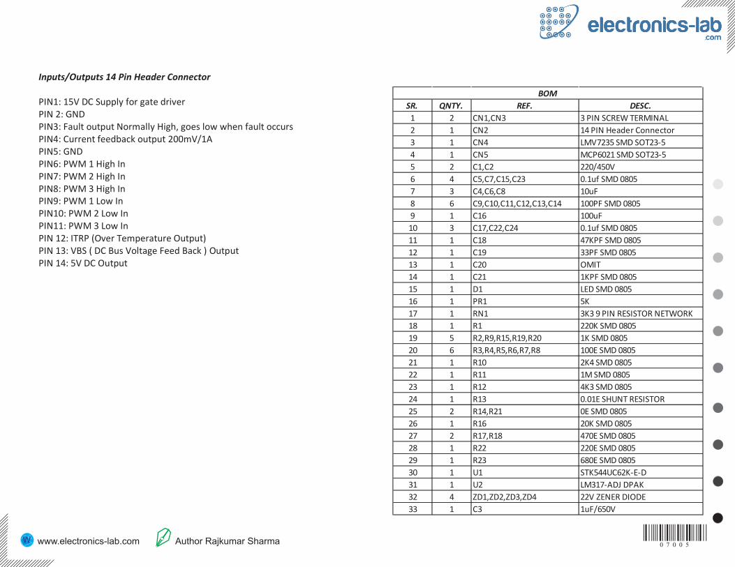
Inputs/Outputs 14 Pin Header Connector PIN1: 15V DC Supply for gate driver PIN 2: GND PIN3: Fault output Normally High, goes low when fault occurs PIN4: Current feedback output 200mV/1A PIN5: GND PIN6: PWM 1 High In PIN7: PWM 2 High In PIN8: PWM 3 High In PIN9: PWM 1 Low In PIN10: PWM 2 Low In PIN11: PWM 3 Low In PIN 12: ITRP (Over Temperature Output) PIN 13: VBS ( DC Bus Voltage Feed Back ) Output PIN 14: 5V DC Output
SR. QNTY. REF. DESC.
1 2 CN1,CN3 3 PIN SCREW TERMINAL
2 1 CN2 14 PIN Header Connector
3 1 CN4 LMV7235 SMD SOT23-5
4 1 CN5 MCP6021 SMD SOT23-5
5 2 C1,C2 220/450V
6 4 C5,C7,C15,C23 0.1uf SMD 0805
7 3 C4,C6,C8 10uF
8 6 C9,C10,C11,C12,C13,C14 100PF SMD 0805
9 1 C16 100uF
10 3 C17,C22,C24 0.1uf SMD 0805
11 1 C18 47KPF SMD 0805
12 1 C19 33PF SMD 0805
13 1 C20 OMIT
14 1 C21 1KPF SMD 0805
15 1 D1 LED SMD 0805
16 1 PR1 5K
17 1 RN1 3K3 9 PIN RESISTOR NETWORK
18 1 R1 220K SMD 0805
19 5 R2,R9,R15,R19,R20 1K SMD 0805
20 6 R3,R4,R5,R6,R7,R8 100E SMD 0805
21 1 R10 2K4 SMD 0805
22 1 R11 1M SMD 0805
23 1 R12 4K3 SMD 0805
24 1 R13 0.01E SHUNT RESISTOR
25 2 R14,R21 0E SMD 0805
26 1 R16 20K SMD 0805
27 2 R17,R18 470E SMD 0805
28 1 R22 220E SMD 0805
29 1 R23 680E SMD 0805
30 1 U1 STK544UC62K-E-D
31 1 U2 LM317-ADJ DPAK
32 4 ZD1,ZD2,ZD3,ZD4 22V ZENER DIODE
33 1 C3 1uF/650V
BOM

0 7 0 0 5 www.electronics-lab.com Author Rajkumar Sharma www.twovolt.com

0 7 0 0 5 www.electronics-lab.com Author Rajkumar Sharma www.twovolt.com
BOTTOM SILK SCREEN BOTTOM TOP SILK SCREEN TOP