Embed Size (px)
Citation preview
10x10G WDM 10km SMF PMD Proposal
Thomas Schrans & Jim Tavacoli
2
schrans_01_0508
Supporters
• Ashby Armistead ― Google• Ralf-Peter Braun ― Deutsche Telekom• Frank Chang ― Vitesse• Pierangelo Chiappa ― Alcatel-Lucent • Xavier Clairardin ― Kotura• Keith Conroy ― AMCC • Chiwu Ding ― Huawei Technologies• Michael Frankel ― Ciena• Ali Ghiasi ― Broadcom• Wenbin Jiang ― Huawei Technologies
• Scott Kipp ― Brocade• Bikash Koley ― Google • Zeng Li ― Huawei Technologies• Hong Liu ― Google • Arlon Martin ― Kotura• Ye Min ― Huawei Technologies• Shantanu Mitra ― Netlogic• Phil McClay ― Zarlink• Robert Snively ― Brocade• Siddharth Sheth, Netlogic
IEEE802.3ba May 2008
3
schrans_01_0508
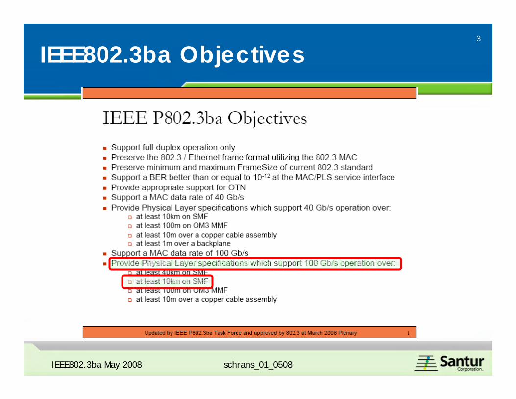
IEEE802.3ba Objectives
IEEE802.3ba May 2008
4
schrans_01_0508
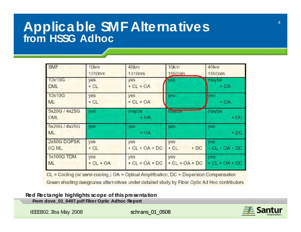
Applicable SMF Alternatives from HSSG Adhoc
IEEE802.3ba May 2008 schrans_01_0508
From dove_01_0407.pdf Fiber Optic Adhoc ReportRed Rectangle highlights scope of this presentation
5
schrans_01_0508IEEE802.3ba May 2008 schrans_01_0508
Outline
• Objective• Why another proposal?• What? • Link Budget• Power Dissipation Budget• Cost• Technical feasibility results
6
schrans_01_0508
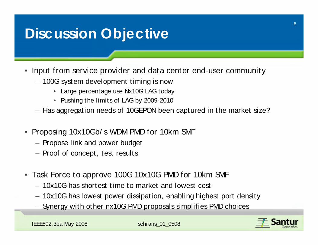
Discussion Objective
• Input from service provider and data center end-user community– 100G system development timing is now
• Large percentage use Nx10G LAG today• Pushing the limits of LAG by 2009-2010
– Has aggregation needs of 10GEPON been captured in the market size?
• Proposing 10x10Gb/s WDM PMD for 10km SMF– Propose link and power budget– Proof of concept, test results
• Task Force to approve 100G 10x10G PMD for 10km SMF– 10x10G has shortest time to market and lowest cost– 10x10G has lowest power dissipation, enabling highest port density– Synergy with other nx10G PMD proposals simplifies PMD choices
IEEE802.3ba May 2008
7
schrans_01_0508
Proposal Overview
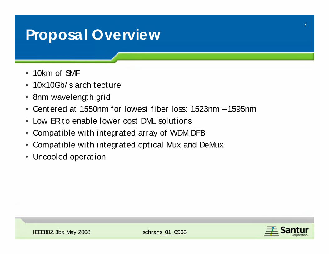
• 10km of SMF • 10x10Gb/s architecture• 8nm wavelength grid• Centered at 1550nm for lowest fiber loss: 1523nm – 1595nm• Low ER to enable lower cost DML solutions• Compatible with integrated array of WDM DFB• Compatible with integrated optical Mux and DeMux• Uncooled operation
IEEE802.3ba May 2008 schrans_01_0508
8
schrans_01_0508schrans_01_0508
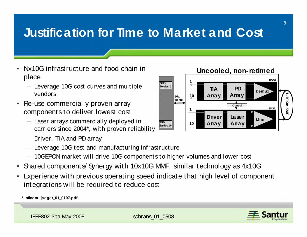
Justification for Time to Market and Cost
– Driver, TIA and PD array – Leverage 10G test and manufacturing infrastructure– 10GEPON market will drive 10G components to higher volumes and lower cost
• Shared components/Synergy with 10x10G MMF, similar technology as 4x10G• Experience with previous operating speed indicate that high level of component
integrations will be required to reduce cost
* Infinera, jaeger_01_0107.pdf
IEEE802.3ba May 2008
1-10Km SM
F
TIAArray
PD Array
1
10
LaserArray
DriverArray
1
10
Control
ROSA
TOSA
Demux.
Mux
Uncooled, non-retimedSFP+Serdes 1
10x10.3G
SFP+Serdes 10
• Nx10G infrastructure and food chain in place– Leverage 10G cost curves and multiple
vendors
• Re-use commercially proven array components to deliver lowest cost– Laser arrays commercially deployed in
carriers since 2004*, with proven reliability
9
schrans_01_0508
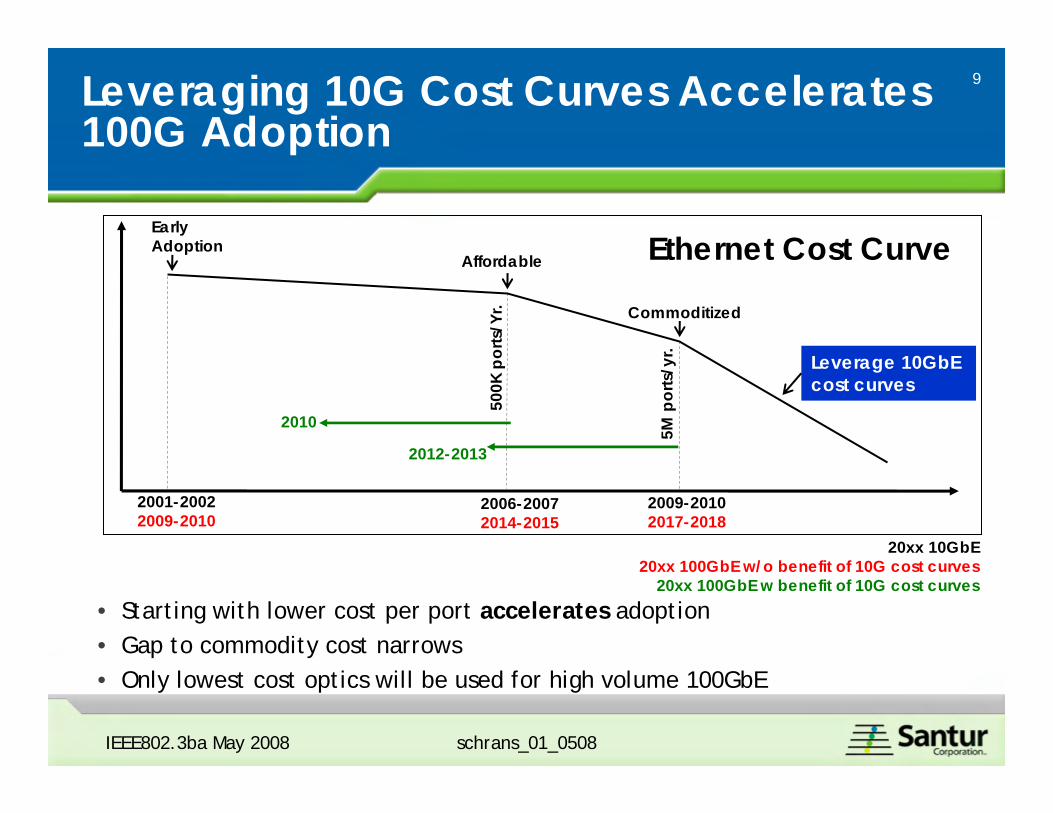
Leveraging 10G Cost Curves Accelerates100G Adoption
Early Adoption
Affordable
Commoditized
2001-20022009-2010
2006-20072014-2015
2009-20102017-2018
500K
por
ts/Y
r.
5M p
orts
/yr.
• Starting with lower cost per port accelerates adoption• Gap to commodity cost narrows• Only lowest cost optics will be used for high volume 100GbE
Leverage 10GbE cost curves
Ethernet Cost Curve
2010
2012-2013
20xx 10GbE20xx 100GbE w/o benefit of 10G cost curves
20xx 100GbE w benefit of 10G cost curves
IEEE802.3ba May 2008
10
schrans_01_0508
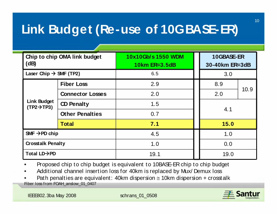
Link Budget (Re-use of 10GBASE-ER)
Chip to chip OMA link budget (dB)
10x10Gb/s 1550 WDM 10km ER=3.5dB
10GBASE-ER30-40km ER=3dB
Laser Chip SMF (TP2) 6.5 3.0
Link Budget (TP2 TP3)
Fiber Loss 2.9 8.910.9
Connector Losses 2.0 2.0
CD Penalty 1.54.1
Other Penalties 0.7
Total 7.1 15.0
SMF PD chip 4.5 1.0
Crosstalk Penalty 1.0 0.0
Total LD PD 19.1 19.0
• Proposed chip to chip budget is equivalent to 10BASE-ER chip to chip budget• Additional channel insertion loss for 40km is replaced by Mux/Demux loss• Path penalties are equivalent: 40km dispersion ≅ 10km dispersion + crosstalkFiber loss from FOAH_anslow_01_0407
IEEE802.3ba May 2008
11
schrans_01_0508IEEE802.3ba May 2008 schrans_01_0508
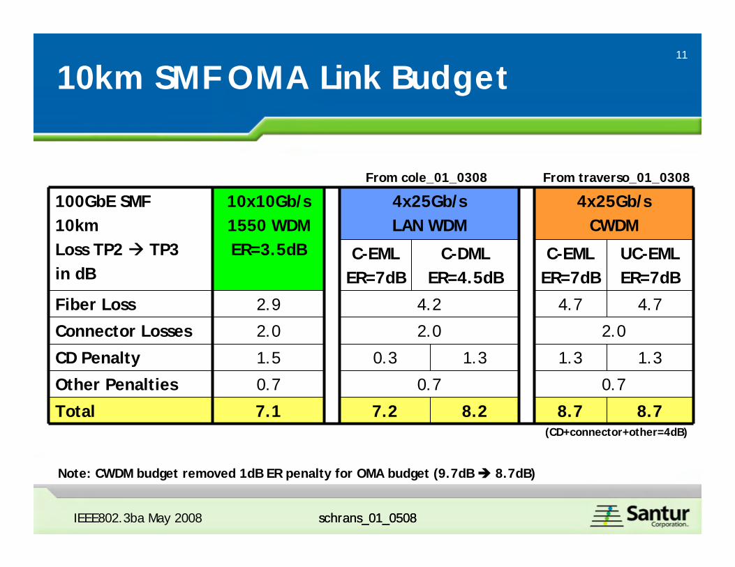
10km SMF OMA Link Budget
100GbE SMF10kmLoss TP2 TP3 in dB
10x10Gb/s1550 WDMER=3.5dB
4x25Gb/sLAN WDM
4x25Gb/sCWDM
C-EMLER=7dB
C-DMLER=4.5dB
C-EMLER=7dB
UC-EMLER=7dB
Fiber Loss 2.9 4.2 4.7 4.7
Connector Losses 2.0 2.0 2.0
CD Penalty 1.5 0.3 1.3 1.3 1.3
Other Penalties 0.7 0.7 0.7
Total 7.1 7.2 8.2 8.7 8.7
Note: CWDM budget removed 1dB ER penalty for OMA budget (9.7dB 8.7dB)
From cole_01_0308 From traverso_01_0308
(CD+connector+other=4dB)
12
schrans_01_0508IEEE802.3ba May 2008 schrans_01_0508
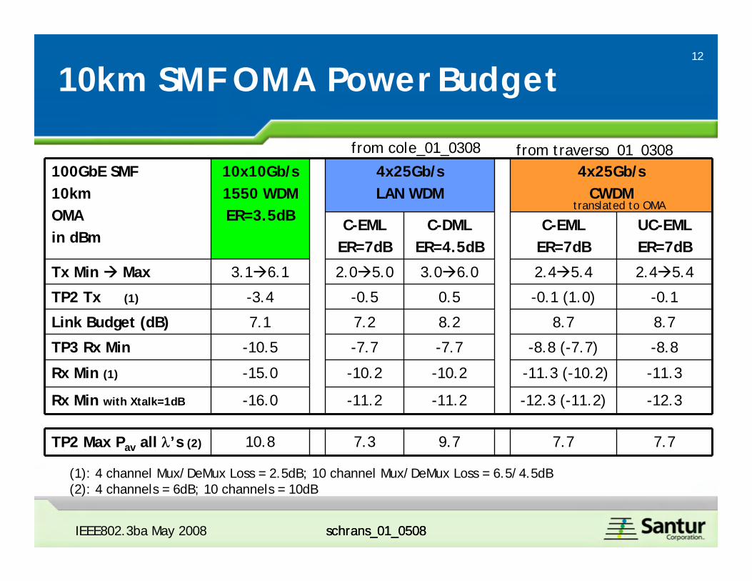
10km SMF OMA Power Budget
100GbE SMF10kmOMAin dBm
10x10Gb/s1550 WDMER=3.5dB
4x25Gb/sLAN WDM
4x25Gb/sCWDM
C-EMLER=7dB
C-DMLER=4.5dB
C-EMLER=7dB
UC-EMLER=7dB
Tx Min Max 3.1 6.1 2.0 5.0 3.0 6.0 2.4 5.4 2.4 5.4
TP2 Tx (1) -3.4 -0.5 0.5 -0.1 (1.0) -0.1
Link Budget (dB) 7.1 7.2 8.2 8.7 8.7
TP3 Rx Min -10.5 -7.7 -7.7 -8.8 (-7.7) -8.8
Rx Min (1) -15.0 -10.2 -10.2 -11.3 (-10.2) -11.3
Rx Min with Xtalk=1dB -16.0 -11.2 -11.2 -12.3 (-11.2) -12.3
TP2 Max Pav all λ’s (2) 10.8 7.3 9.7 7.7 7.7
(1): 4 channel Mux/DeMux Loss = 2.5dB; 10 channel Mux/DeMux Loss = 6.5/4.5dB(2): 4 channels = 6dB; 10 channels = 10dB
from cole_01_0308 from traverso_01_0308
translated to OMA
13
schrans_01_0508IEEE802.3ba May 2008 schrans_01_0508
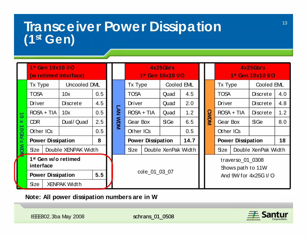
Transceiver Power Dissipation (1st Gen)
1st Gen 10x10 I/O(w retimed interface)
4x25Gb/s1st Gen 10x10 I/O
4x25Gb/s1st Gen 10x10 I/O
10 x 10Gb/s W
DM
Tx Type Uncooled DML
LAN
WD
M
Tx Type Cooled EML
CWD
M
Tx Type Cooled EML
TOSA 10x 0.5 TOSA Quad 4.5 TOSA Discrete 4.0
Driver Discrete 4.5 Driver Quad 2.0 Driver Discrete 4.8
ROSA + TIA 10x 0.5 ROSA + TIA Quad 1.2 ROSA + TIA Discrete 1.2
CDR Dual/Quad 2.5 Gear Box SiGe 6.5 Gear Box SiGe 8.0
Other ICs 0.5 Other ICs 0.5 Other ICs
Power Dissipation 8 Power Dissipation 14.7 Power Dissipation 18
Size Double XENPAK Width Size Double XenPak Width Size Double XenPak Width
1st Gen w/o retimed interface
cole_01_03_07
traverso_01_0308Shows path to 11WAnd 9W for 4x25G I/OPower Dissipation 5.5
Size XENPAK Width
Note: All power dissipation numbers are in W
14
schrans_01_0508IEEE802.3ba May 2008 schrans_01_0508
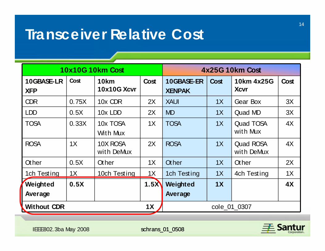
Transceiver Relative Cost
10x10G 10km Cost 4x25G 10km Cost10GBASE-LRXFP
Cost 10km 10x10G Xcvr
Cost 10GBASE-ER XENPAK
Cost 10km 4x25G Xcvr
Cost
CDR 0.75X 10x CDR 2X XAUI 1X Gear Box 3X
LDD 0.5X 10x LDD 2X MD 1X Quad MD 3X
TOSA 0.33X 10x TOSAWith Mux
1X TOSA 1X Quad TOSA with Mux
4X
ROSA 1X 10X ROSA with DeMux
2X ROSA 1X Quad ROSA with DeMux
4X
Other 0.5X Other 1X Other 1X Other 2X
1ch Testing 1X 10ch Testing 1X 1ch Testing 1X 4ch Testing 1X
Weighted Average
0.5X 1.5X Weighted Average
1X 4X
Without CDR 1X cole_01_0307
15
schrans_01_0508
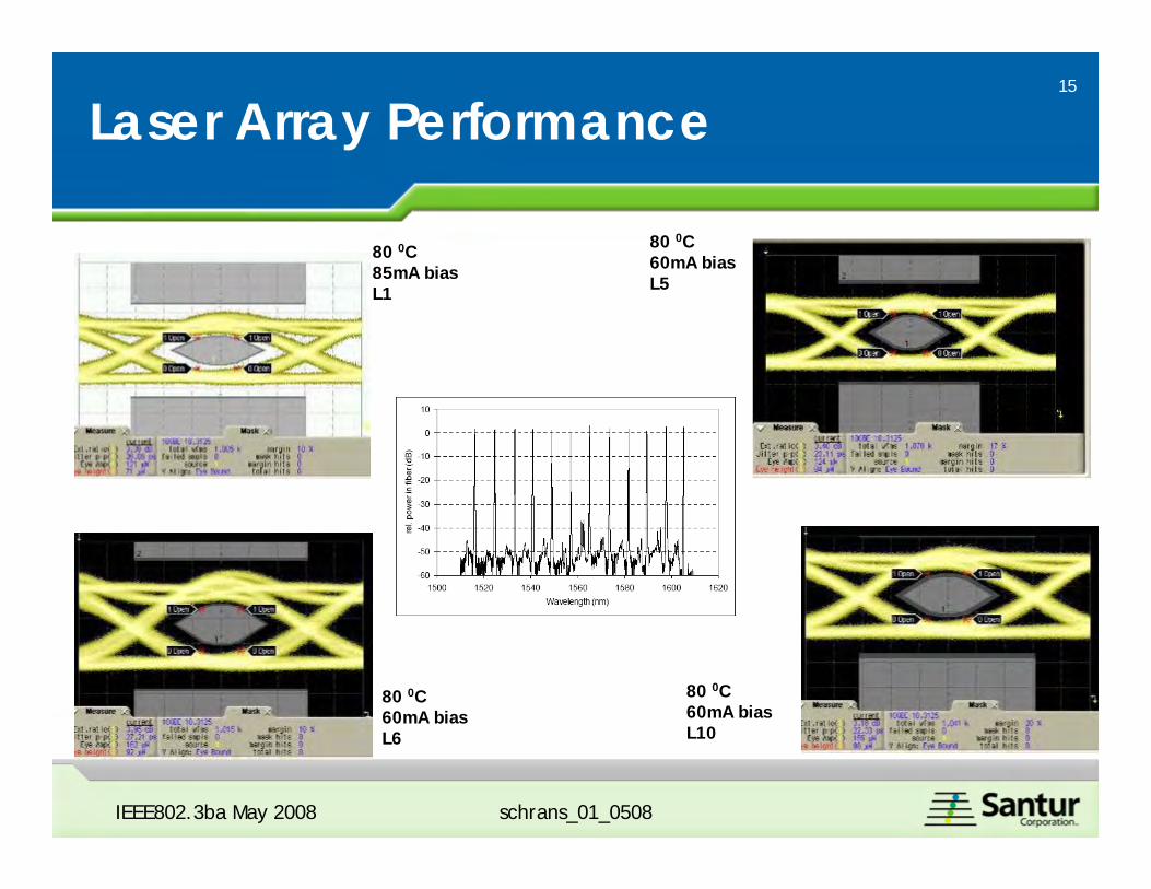
Laser Array Performance
80 0C85mA biasL1
80 0C60mA biasL6
80 0C60mA biasL10
IEEE802.3ba May 2008
80 0C60mA biasL5
16
schrans_01_0508
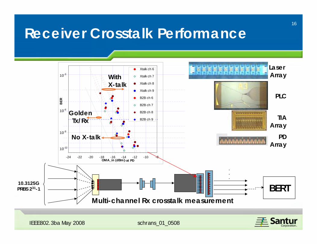
Receiver Crosstalk Performance
IEEE802.3ba May 2008
Laser Array
PDArray
TIAArray
PLC
10.3125G PRBS 231-1 BERT
.
.
.
Multi-channel Rx crosstalk measurement
-24 -22 -20 -18 -16 -14 -12 -10 -8OMA_in (dBm)
BER
Xtalk ch 6
Xtalk ch 7
Xtalk ch 8
Xtalk ch 9
B2B ch 6
B2B ch 7
B2B ch 8
B2B ch 9
10-3
10-6
10-9
10-12
No X-talk
With X-talk
GoldenTx/Rx
-at PD
17
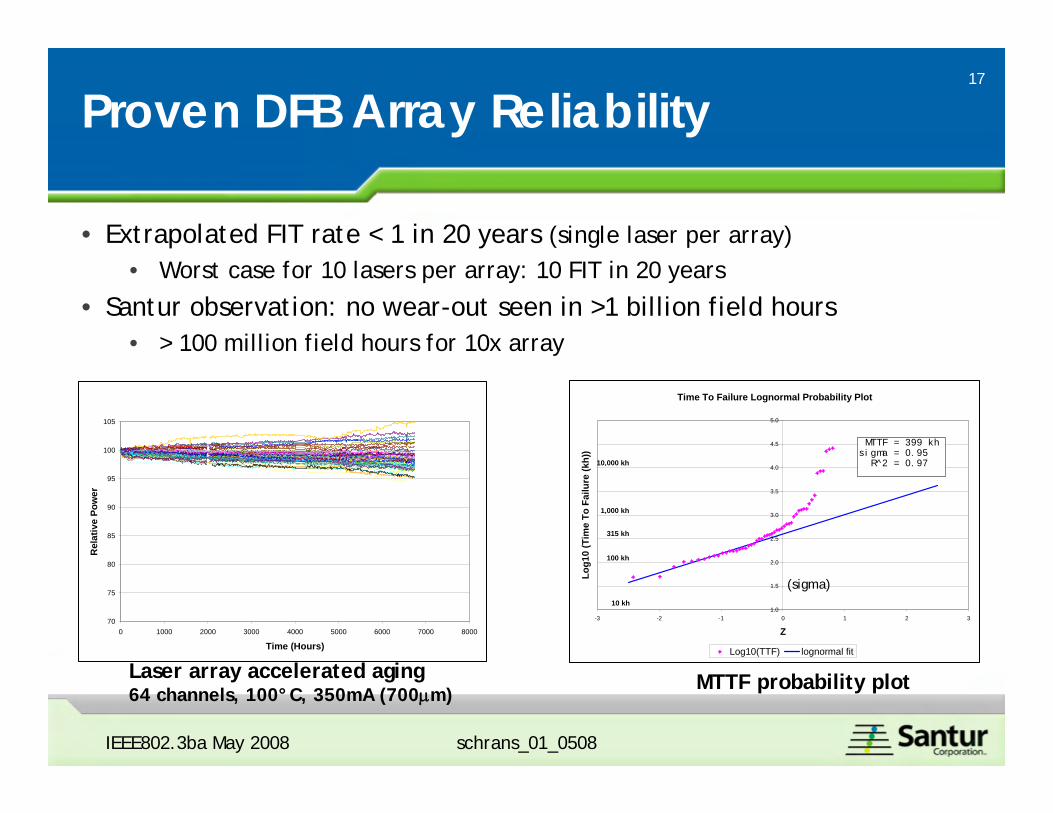
Proven DFB Array Reliability
Al/Hf laser lifetest (64 diodes at 110C, 350mA)
70
75
80
85
90
95
100
105
0 1000 2000 3000 4000 5000 6000 7000 8000
Time (Hours)
Rel
ativ
e Po
wer
Laser array accelerated aging64 channels, 100°C, 350mA (700µm)
Time To Failure Lognormal Probability Plot
1.0
1.5
2.0
2.5
3.0
3.5
4.0
4.5
5.0
-3 -2 -1 0 1 2 3
Z
Log1
0 (T
ime
To F
ailu
re (k
h))
Log10(TTF) lognormal fit
10 kh
10,000 kh
1,000 kh
100 kh
315 kh
MTTF = 399 khsigma = 0.95 R^2 = 0.97
MTTF probability plot
• Extrapolated FIT rate < 1 in 20 years (single laser per array)• Worst case for 10 lasers per array: 10 FIT in 20 years
• Santur observation: no wear-out seen in >1 billion field hours• > 100 million field hours for 10x array
(sigma)
IEEE802.3ba May 2008 schrans_01_0508
18
schrans_01_0508
10x10Gb/s Scalable to other 802.3ba PMDs
IEEE802.3ba May 2008 schrans_01_0508
• 40Gb/s 10km SMF– Use 8nm grid and reduced wavelength range– Use same wavelength range with increased wavelength grid of 20nm
• Increased uncooled temperature range, lower cost Mux/Demux– Re-use of same LDD, TIA, PD cells
• 100Gb/s 40km SMF– Additional Channel Insertion Loss compared to 10km
• 30km x 0.29dB/km = 8.7dB– 1550 EML
• 3.5dB ER to 7dB ER gain of 2.4dB in OMA without increasing Pmax
– Additional Channel Insertion Loss is partially compensated resulting in needing 6.3dB more gain
– This 6.3dB can easily be achieved with APD, FEC/EDC, SOA
19
schrans_01_0508
Conclusion
IEEE802.3ba May 2008 schrans_01_0508
• Propose a 10x10G 1550nm WDM 10km SMF PMD• Scalable to 4x10Gb/s over 10km SMF• Scalable to 10x10Gb/s over 40km SMF
• Demonstrated technical feasibility
• This proposal is the lowest cost, lowest power, uncooled solution • Proven 10G laser arrays (performance and reliability)• Leverage 10G cost curves, adopt Nx10G common scheme
• Uses viable, proven electro-optical components based on known specification methodologies
• Leverages common components, technologies, testing and manufacturing infrastructures with 100G 10x10 MMF PMD’s and 40G 4x10 SMF/MMF PMD’s