Embed Size (px)
Citation preview
1.1-1.7-2.2-3 kVAInstallation and operating manual GB
004
DR
WN
ETR
T-X
X
2 1.1-3 kVA - Ref.: IOMNETRTXX00-GB 00
This SOCOMEC UPS appliance is guaranteed against possible defects of manufacture and materials, for a period of 12 months from the date of purchase (local warranty conditions are applicable in addition to the general conditions). The present warranty certificate should NOT be mailed, but kept by the customer together with the proof of purchase document, for use in the event of a claim being made for repairs or replacement under warranty.
The warranty period runs from the date on which the new product was purchased by the end user at the showroom of an official resaler (the reference data is that indicated on the proof-of-purchase document).
The warranty is offered on carry-in terms: components and labour for repairs supplied free of charge, and in the case of a replace-ment, the product to be returned to SOCOMEC UPS or to authorized service centres, at the customer’s own risk and expense.
To claim service under warranty, the user must abide by the following rules:
• The product is to be returned only in the original packing. Any damage occurring in transit to a product not in its original packing will not be covered by the warranty;
• The product must be accompanied by proof of purchase: a document (delivery note, invoice, counter receipt) indicating the date of the purchase, which must also indicate the essential identification data for the product (model, serial numer). The sender must also attach the acceptance number issued to authorize the return of the product, together with a detailed description of the defect encountered. If any of these elements is missing, the warranty will be invalidated. The authorization number is issued by service centres over the telephone, after being informed of the malfunction in respect of which a claim is submitted;
• Should it be impossible to furnish proof of purchase, the serial number and date of manufacture will be used to calculate the probable expiry date of the warranty; this could result in a reduction of the original warranty period.
The warranty on the product does not cover damage occasioned by thoughtlessness (improper use: wrong input power, explosions, excessive humidity, temperature, poor ventilation, etc.), tampering or any unauthorized repair work.
During the warranty period, SOCOMEC UPS remains at liberty to decide whether the product should be repaired, or whether to replace defective parts with new parts, or with used parts that are equivalent to new parts in terms of functionality and perfor-mance.
In the case of batteries, warranty is valid only if the battery has been recharged periodically in accordance with the manufacturer’s directions. Accordingly, it is advisable to check, following purchase, that the date of the next recharge indicated on the packing has not expired.
Optionals.
A 12-month carry-in warranty is offered on optionals.
Software products.
Software products are guaranteed for 90 days. The software is guaranteed to work substantially as indicated in the manual accom-panying the product. Hardware media or accessories (e.g. diskettes, cables, etc.) used with appliances are guaranteed free of material or manufacturing defects under normal conditions of use for a period of 12 months from the date of purchase.
On no account will SOCOMEC UPS ackowledge liability for damages (including loss of income, interruption of business activity, loss of information or other economic losses, of whatever magnitude) deriving from the use of the product.
The present conditions are regulated by the laws of Italy. Disputes shall be submitted to the jurisdiction of the Vicenza Law Courts.
WARRANTY CERTIFICATE AND CONDITIONS
SOCOMEC UPS retains the full and exclusive ownership rights over this document. Only a personal right to utilize the document for the application indicated by SOCOMEC UPS is granted to the recipient of such document. All reproduction, modification, dissemi-nation of this document whether in part or whole and by any manner are expressly prohibited except upon Socomec’s express prior written consent.
This document is not a specification. SOCOMEC UPS reserves the right to make any changes to data without prior notice.
3 1.1-3 kVA - Ref.: IOMNETRTXX00-GB 00
TABLE OF CONTENTS
EN
GLI
SH
1. SAFETY STANDARDS. . . . . . . . . . . . . . . . . . . . . . . . . . . . . . . . . . . . . . . . . . . . . . . . . . . . . . 41.1 Important . . . . . . . . . . . . . . . . . . . . . . . . . . . . . . . . . . . . . . . . . . . . . . . . . . . . . . . 41.2 Description of the symbols used on the labels applied to the unit . . . . . . . . . . . . . 5
2. INSTALLATION . . . . . . . . . . . . . . . . . . . . . . . . . . . . . . . . . . . . . . . . . . . . . . . . . . . . . . . . . . . 62.1 Environmental requirements for installation . . . . . . . . . . . . . . . . . . . . . . . . . . . . . . 62.2 Vertical installation . . . . . . . . . . . . . . . . . . . . . . . . . . . . . . . . . . . . . . . . . . . . . . . . 72.3 Horizontal installation on rack . . . . . . . . . . . . . . . . . . . . . . . . . . . . . . . . . . . . . . . . 9
3. REAR VIEW . . . . . . . . . . . . . . . . . . . . . . . . . . . . . . . . . . . . . . . . . . . . . . . . . . . . . . . . . . . . . 12
4. CONNECTIONS . . . . . . . . . . . . . . . . . . . . . . . . . . . . . . . . . . . . . . . . . . . . . . . . . . . . . . . . . 13
5. CONNECTION OF BATTERY EXTENSION . . . . . . . . . . . . . . . . . . . . . . . . . . . . . . . . . . . . . 145.1 Safety warnings . . . . . . . . . . . . . . . . . . . . . . . . . . . . . . . . . . . . . . . . . . . . . . . . . 145.2 Connection of battery extension . . . . . . . . . . . . . . . . . . . . . . . . . . . . . . . . . . . . . 14
6. MIMIC PANEL . . . . . . . . . . . . . . . . . . . . . . . . . . . . . . . . . . . . . . . . . . . . . . . . . . . . . . . . . . . 16
7. OPERATING MODES . . . . . . . . . . . . . . . . . . . . . . . . . . . . . . . . . . . . . . . . . . . . . . . . . . . . . 177.1 Battery recharge . . . . . . . . . . . . . . . . . . . . . . . . . . . . . . . . . . . . . . . . . . . . . . . . . 177.2 Switching the Netys RT ON and OFF . . . . . . . . . . . . . . . . . . . . . . . . . . . . . . . . . 177.3 Rated Output Voltage Setting . . . . . . . . . . . . . . . . . . . . . . . . . . . . . . . . . . . . . . . 19
8. VISUAL AND AUDIBLE WARNING SIGNALS . . . . . . . . . . . . . . . . . . . . . . . . . . . . . . . . . . . 20
9. COMMUNICATION . . . . . . . . . . . . . . . . . . . . . . . . . . . . . . . . . . . . . . . . . . . . . . . . . . . . . . . 219.1 Communication solutions . . . . . . . . . . . . . . . . . . . . . . . . . . . . . . . . . . . . . . . . . . 219.2 USB interface . . . . . . . . . . . . . . . . . . . . . . . . . . . . . . . . . . . . . . . . . . . . . . . . . . . 219.3 RS232 interface . . . . . . . . . . . . . . . . . . . . . . . . . . . . . . . . . . . . . . . . . . . . . . . . . 219.4 WEB/SNMP card . . . . . . . . . . . . . . . . . . . . . . . . . . . . . . . . . . . . . . . . . . . . . . . . 219.5 Use of warning relay interface . . . . . . . . . . . . . . . . . . . . . . . . . . . . . . . . . . . . . . . 21
10. MAINTENANCE . . . . . . . . . . . . . . . . . . . . . . . . . . . . . . . . . . . . . . . . . . . . . . . . . . . . . . . . . 2410.1 Minor troubleshooting . . . . . . . . . . . . . . . . . . . . . . . . . . . . . . . . . . . . . . . . . . . . 24
11. TECHNICAL SPECIFICATIONS . . . . . . . . . . . . . . . . . . . . . . . . . . . . . . . . . . . . . . . . . . . . 25
4 1.1-3 kVA - Ref.: IOMNETRTXX00-GB 00
1. SAFETY STANDARDS
1.1 Important
This manual should be kept carefully in a safe place near the UPS, so that it can be consulted by the operator at any time for any information that may be needed regarding correct use of the unit. Read the manual carefully before connecting the unit to the a.c. mains supply and to the downstream appliances. Before the UPS NETYS RT is put into commission, the user must be perfectly familiar with its operation, with the position of all the controls and with the technical and functional characteristics of the unit, so as to ensure there will be no risk to any persons or to the appliance itself.
• Before being started up, the unit must be equipotentially bonded, in accordance with current safety regulations. The earth wire of the UPS must then be connected to an efficient earth system.
• If the earth connection is not made, the appliances connected to the UPS will not be equipotentially bonded. In this situation, the manufacturer declines all liability for any damage or accidents that could derive from failure to observe the requirements.
• Should a power outage occur (UPS in stand-alone mode), do not disconnect the power cord from the mains, as this will break the earth connection to bonded appliances.
• All subsequent maintenance operations must be entrusted only to authorized service engineers. The UPS generates high internal voltages that could be hazardous for a maintenance operative not in possession of the appropriate skills and training for this type of work.
• If a hazard situation should arise at any moment when the UPS is in use, isolate the unit from the power supply (by operating a switch at the upstream PDU if possible) and switch the appliance off completely by running the shutdown procedure.
• The UPS houses a source of electrical energy, namely its batteries. The output of the UPS may be under power even when the appliance is not connected to the a.c. mains supply.
• Never force, break or attempt to open the batteries. These batteries are sealed, maintenance-free components contai-ning substances that are harmful to health and a source of environmental pollution. If liquid can be seen leaking from the battery, or a white powdery residue is noticeable, do not switch the UPS on.
• Avoid exposing the UPS to contact with water or any liquids generally. Do not insert foreign objects into the cabinet.
• If the appliance is to be scrapped, it must be entrusted exclusively to a specialist waste disposal company. These companies will split up and dispose of the various components in accordance with statutory regulations in the country of purchase.
• Since the power cord of the UPS functions as an isolating device, ensure ready access to the mains power socket where the UPS is connected, and/or to the rear panel of the UPS, so the unit can be easily unplugged.
• The UPS generates a leakage current of approximately 3 mA. To guarantee the maximum leakage current of 3.5 mA, make certain that the leakage current generated by the load is no greater than 0.5 mA. Should the leakage current from the load exceed this limit, instruct a skilled engineer to install an industrial type connection (to IEC 309 standard) between the UPS and the a.c. mains supply, sized to handle a current compatible with the rating of the appliance.
• Use the UPS in accordance with the technical specifications indicated in this manual (chapter 11).
• To meet the operating requirements for the Emergency Switch Device (ESD), a specific RJ11 input with remote ESD/EPO function is available.
• In the event that the equipment has no automatic backfeed protection contactor device, make certain that:
- the user/installer attaches warning labels to all mains isolating switches located remotely from the area where the UPS is sited, in order to inform service personnel that the circuit is connected to a UPS.
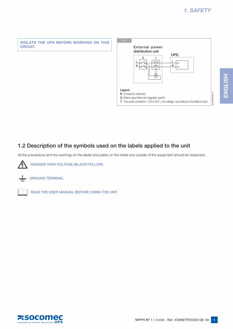
- an external isolating device is installed, as indicated in figure 1-1.
• The product you have selected, given the specified conditions of use, capacity and performance limits, is designed exclusively for commercial and industrial service. The use of the product in “critical applications” could require compliance with statutory regula-tions and standards, or with specific local bylaws, or adaptation to SOCOMEC UPS recommendations. For this type of use, in any event, it is advisable to contact SOCOMEC UPS beforehand for confirmation regarding the capacity of products to meet required levels of safety, performance and reliability. The expression “critical applications” covers, in particular, life support systems, medical applications, commercial transport, nuclear facilities or any other systems where failure of the product might on occasion cause serious damage to persons or property.
WARNING!This is a product for commercial and industrial application in the second environment – installation restrictions or additional measures may be needed to prevent disturbances.
5 1.1-3 kVA - Ref.: IOMNETRTXX00-GB 00
EN
GLI
SH
L
Q
N
T
B
L
N
1. SAFETY
1.2 Description of the symbols used on the labels applied to the unit
All the precautions and the warnings on the labels and plates on the inside and outside of the equipment should be respected.
DANGER! HIGH VOLTAGE (BLACK/YELLOW)
GROUND TERMINAL
READ THE USER MANUAL BEFORE USING THE UNIT
085
DR
WN
ETR
T-X
X
1-1
Legend. B Contactor solenoid.Q Mains input thermal-magnetic switchT Two-pole contactor > 30 A AC1; coil voltage: according to the Mains input.
UPS.
External power distribution unit
ISOLATE THE UPS BEFORE WORKING ON THIS CIRCUIT.
6 1.1-3 kVA - Ref.: IOMNETRTXX00-GB 00
2. INSTALLATION
2.1 Environmental requirements for installation
Consult the following check list when installing the UPS:
• NETYS RT units are designed for use in enclosed environments.
• Position the UPS on a flat and stable surface in a properly ventilated room, well away from heat sources and avoiding direct exposure to sunlight.
• Ambient temperature should be maintained between 0 °C and 40 °C, and relative humidity below 90% (without condensation); the optimum temperature in terms of maximizing battery life is 15-20 °C.
• Check that the UPS will not be installed in a dust-laden environment.
• Be certain that a clearance of at least 20 cm is left on all sides of the unit to ensure adequate ventilation and provide access to the rear panel.
• Take care not to stand the UPS or any other heavy object on cables.
• Check that the operating voltage and frequency settings are correct for the mains power supply at the installation site. Details for the UPS will be found on the data plate affixed to the rear panel.
• When making the RS232 serial connection, use only the cables and accessories supplied or specified by the manufacturer.
• When the UPS is first used, it is advisable to leave the battery on charge for a minimum of 8 hours.
PRECAUTIONS IN THE EVENT OF DAMAGE
DO NOT OVERTURN THE BATTERIES.
Packing materials that have been broken, punctured or torn in such a way as to reveal the contents must be kept separate in a secure area, and inspected by skilled staff. Any packing considered unsuitable for shipment of the contents must be set aside immediately and kept secure, and the sender or recipient contacted.
Electrical requirements
UPS Thermal-magnetic switch on input
Recommended selective RCD on input
Cable section
1.1 kVA 10 C 0,1 A type B to IEC
1.7 kVA 16 C 0,1 A type B to IEC
2.2 kVA 20 C 0,1 A type B to IEC
3.0 kVA 20 C 0,1 A type B to IEC
7 1.1-3 kVA - Ref.: IOMNETRTXX00-GB 00
EN
GLI
SH
2. INSTALLATION
=
=
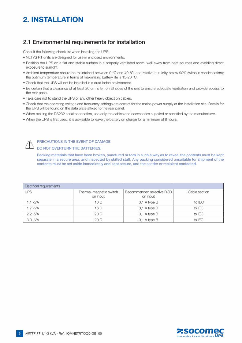
2.2 Vertical installation
2.2.1 UPS Installation
2.2.2 UPS Installation with 1 battery extension
4
4
2
1
3
026
DR
WN
ETR
T-X
X
031
DR
WN
ETR
T-X
X
035
DR
WN
ETR
T-X
X
059
DR
WN
ETR
T-X
X
027
DR
WN
ETR
T-X
X
8 1.1-3 kVA - Ref.: IOMNETRTXX00-GB 00
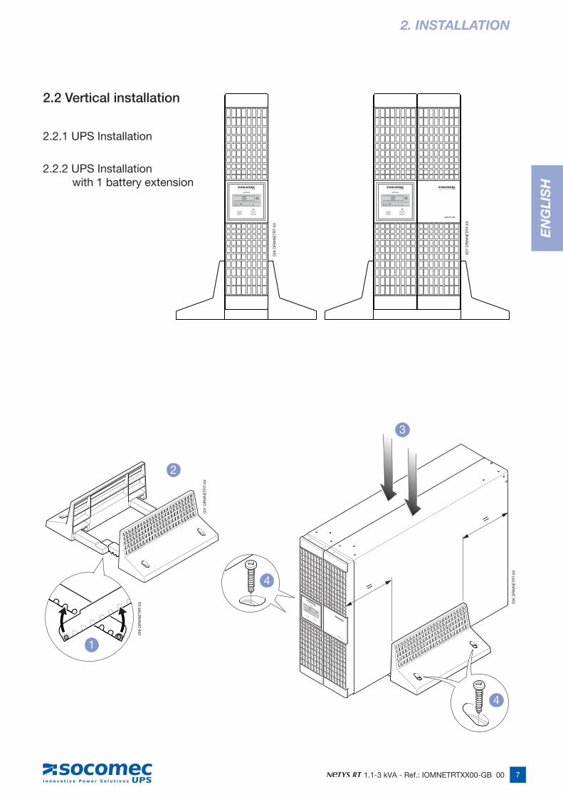
2.2.3 UPS Installation with multiple battery extensions
2. INSTALLATION
=
=
4
2
1
3
036
DR
WN
ETR
T-X
X
033
DR
WN
ETR
T-X
X
059
DR
WN
ETR
T-X
X
028
DR
WN
ETR
T-X
X
9 1.1-3 kVA - Ref.: IOMNETRTXX00-GB 00
EN
GLI
SH
2. INSTALLATION
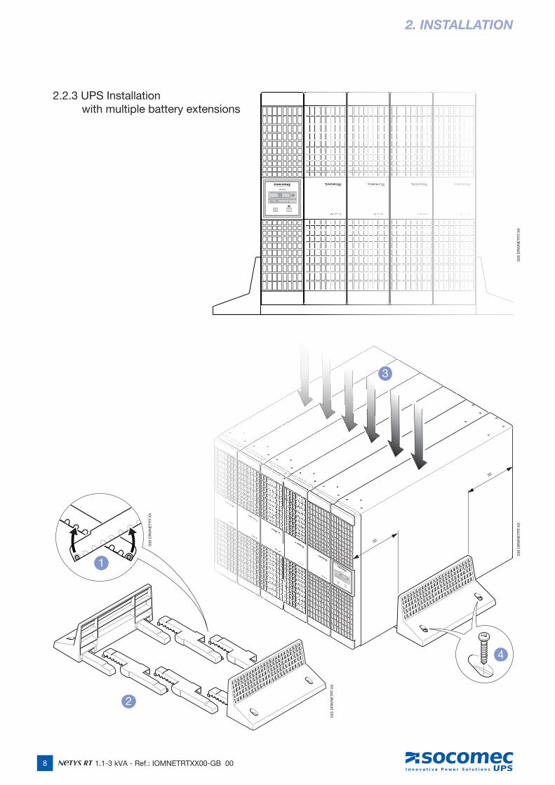
2.3 Horizontal installation on rack
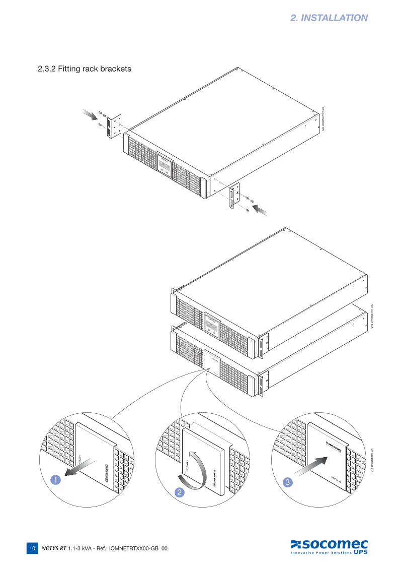
2.3.1 Rotation of mimic pannel
038
DR
WN
ETR
T-X
X04
3 D
RW
NE
TRT-
XX
042
DR
WN
ETR
T-X
X04
1 D
RW
NE
TRT-
XX
039
DR
WN
ETR
T-X
X
1
2
3
10 1.1-3 kVA - Ref.: IOMNETRTXX00-GB 00
2.3.2 Fitting rack brackets
2. INSTALLATION
044
DR
WN
ETR
T-X
X
046
DR
WN
ETR
T-X
X
1
23
045
DR
WN
ETR
T-X
X
11 1.1-3 kVA - Ref.: IOMNETRTXX00-GB 00
EN
GLI
SH
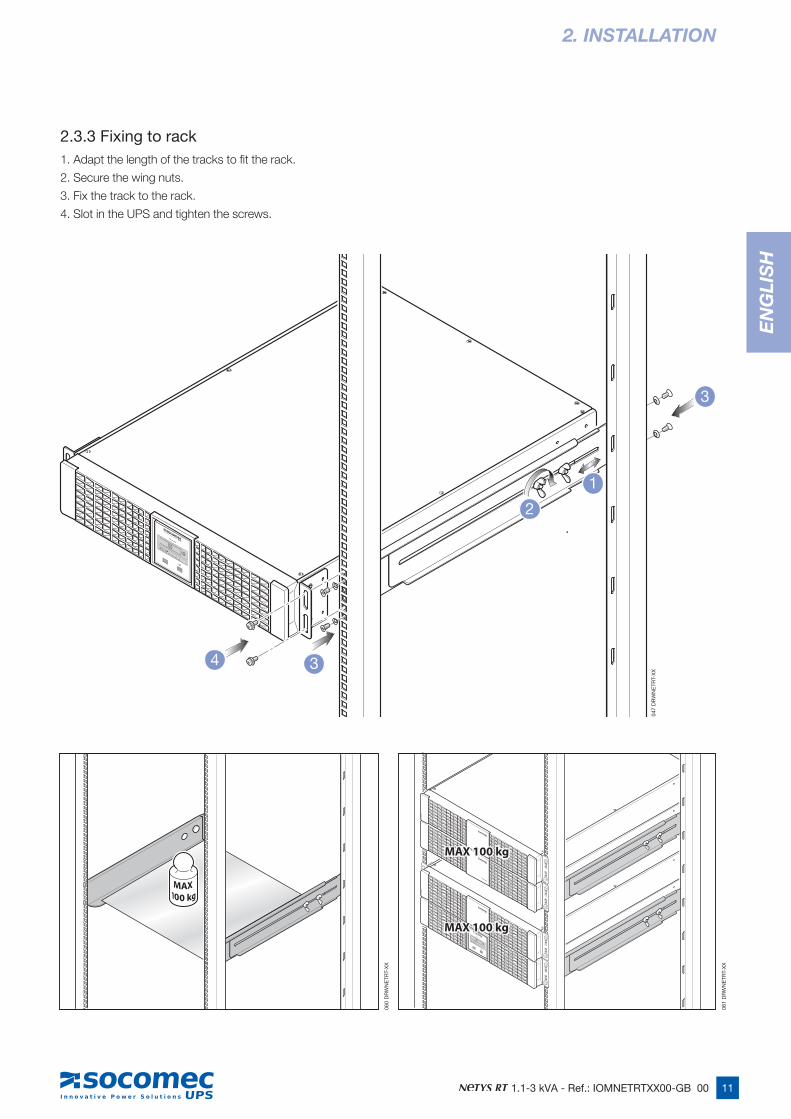
2.3.3 Fixing to rack1. Adapt the length of the tracks to fit the rack.
2. Secure the wing nuts.
3. Fix the track to the rack.
4. Slot in the UPS and tighten the screws.
2. INSTALLATION
MAX 100 kgMAX 100 kg
MAX 100 kgMAX 100 kg
3
3
1
2
4
060
DR
WN
ETR
T-X
X
047
DR
WN
ETR
T-X
X
061
DR
WN
ETR
T-X
X
12 1.1-3 kVA - Ref.: IOMNETRTXX00-GB 00
3. REAR VIEW
LOA
D 1
LOA
D 2
INO
UT
BR
EA
KE
RIN
PU
T
INP
UT
RS
232E
PO
SU
RG
E P
RO
TEC
T
40A24V
CO
M. S
LOT
INO
UT
LOA
D 1
LOA
D 2
RS
232
BR
EA
KE
RIN
PU
T
EP
OS
UR
GE
PR
OTE
CT
LOA
D 3
INP
UT
40A72V
CO
M. S
LOT
INO
UT
LOA
D 1
LOA
D 2
RS
232
BR
EA
KE
RIN
PU
T
EP
OS
UR
GE
PR
OTE
CT
LOA
D 3
INP
UT
40A48V
CO
M. S
LOT
1100 VA 3000 VA1700 VA2200 VA
GGG
FFF
EEE
D DD
BBB
CC
HHH
L
LL
L
M P
L
NN
I
IIA AA
L
O
N
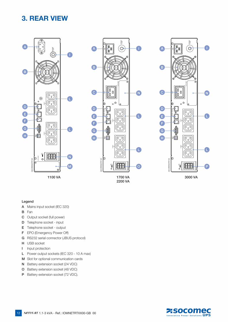
Legend
A Mains input socket (IEC 320)
B Fan
C Output socket (full power)
D Telephone socket - input
E Telephone socket - output
F EPO (Emergency Power Off)
G RS232 serial connector (JBUS protocol)
H USB socket
I Input protection
L Power output sockets (IEC 320 - 10 A max)
M Slot for optional communication cards
N Battery extension socket (24 VDC)
O Battery extension socket (48 VDC)
P Battery extension socket (72 VDC).
048
DR
WN
ETR
T-X
X
049
DR
WN
ETR
T-X
X
040
DR
WN
ETR
T-X
X
13 1.1-3 kVA - Ref.: IOMNETRTXX00-GB 00
EN
GLI
SH
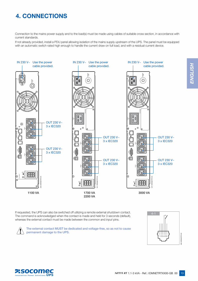
Connection to the mains power supply and to the load(s) must be made using cables of suitable cross section, in accordance with current standards.
If not already provided, install a PDU panel allowing isolation of the mains supply upstream of the UPS. The panel must be equipped with an automatic switch rated high enough to handle the current draw on full load, and with a residual current device.
If requested, the UPS can also be switched off utilizing a remote external shutdown contact. The command is acknowledged when the contact is made and held for 3 seconds (default), whereas the external contact must be made between the common and input pins.
The external contact MUST be dedicated and voltage-free, so as not to cause permanent damage to the UPS.
4. CONNECTIONS
1100 VA 3000 VA1700 VA2200 VA
LOA
D 1
LOA
D 2
INO
UT
BR
EA
KE
RIN
PU
T
INP
UT
RS
232E
PO
SU
RG
E P
RO
TEC
T
40A24V
CO
M. S
LOT
INO
UT
LOA
D 1
LOA
D 2
RS
232
BR
EA
KE
RIN
PU
T
EP
OS
UR
GE
PR
OTE
CT
LOA
D 3
INP
UT
40A72V
CO
M. S
LOT
INO
UT
LOA
D 1
LOA
D 2
RS
232
BR
EA
KE
RIN
PU
T
EP
OS
UR
GE
PR
OTE
CT
LOA
D 3
INP
UT
40A48V
CO
M. S
LOT
OUT 230 V~3 x IEC320
OUT 230 V~3 x IEC320
OUT 230 V~3 x IEC320
OUT 230 V~3 x IEC320
OUT 230 V~3 x IEC320
OUT 230 V~3 x IEC320
IN 230 V~ Use the power cable provided.
IN 230 V~ Use the power cable provided.
IN 230 V~ Use the power cable provided.
1 2 3 4 5 6
4-1
050
DR
WN
ETR
T-X
X
051
DR
WN
ETR
T-X
X
037
DR
WN
ETR
T-X
X
062
DR
WN
ETR
T-X
X
14 1.1-3 kVA - Ref.: IOMNETRTXX00-GB 00
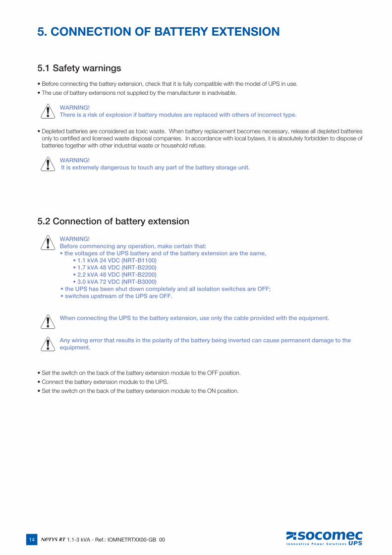
5.1 Safety warnings
• Before connecting the battery extension, check that it is fully compatible with the model of UPS in use.
• The use of battery extensions not supplied by the manufacturer is inadvisable.
WARNING! There is a risk of explosion if battery modules are replaced with others of incorrect type.
• Depleted batteries are considered as toxic waste. When battery replacement becomes necessary, release all depleted batteries only to certified and licensed waste disposal companies. In accordance with local bylaws, it is absolutely forbidden to dispose of batteries together with other industrial waste or household refuse.
WARNING! It is extremely dangerous to touch any part of the battery storage unit.
5.2 Connection of battery extension
WARNING! Before commencing any operation, make certain that:• the voltages of the UPS battery and of the battery extension are the same,
• 1.1 kVA 24 VDC (NRT-B1100) • 1.7 kVA 48 VDC (NRT-B2200) • 2.2 kVA 48 VDC (NRT-B2200) • 3.0 kVA 72 VDC (NRT-B3000) • the UPS has been shut down completely and all isolation switches are OFF; • switches upstream of the UPS are OFF.
When connecting the UPS to the battery extension, use only the cable provided with the equipment.
Any wiring error that results in the polarity of the battery being inverted can cause permanent damage to the equipment.
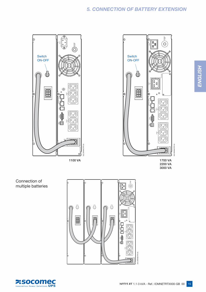
• Set the switch on the back of the battery extension module to the OFF position.
• Connect the battery extension module to the UPS.
• Set the switch on the back of the battery extension module to the ON position.
5. CONNECTION OF BATTERY EXTENSION
15 1.1-3 kVA - Ref.: IOMNETRTXX00-GB 00
EN
GLI
SH
5. CONNECTION OF BATTERY EXTENSION
LOA
D 1
LOA
D 2
INO
UT
BR
EA
KE
RIN
PU
T
INP
UT
RS
232E
PO
SU
RG
E P
RO
TEC
T
40A24V
CO
M. S
LOT
INO
UT
LOA
D 1
LOA
D 2
RS
232
BR
EA
KE
RIN
PU
T
EP
OS
UR
GE
PR
OTE
CT
LOA
D 3
INP
UT
40A48V
CO
M. S
LOT
1100 VA 1700 VA2200 VA3000 VA
INO
UT
LOA
D 1
LOA
D 2
RS
232
BR
EA
KE
RIN
PU
T
EP
OS
UR
GE
PR
OTE
CT
LOA
D 3
INP
UT
40A48V
CO
M. S
LOT
Connection ofmultiple batteries
SwitchON-OFF
SwitchON-OFF
052
DR
WN
ETR
T-X
X
053
DR
WN
ETR
T-X
X
054
DR
WN
ETR
T-X
X
16 1.1-3 kVA - Ref.: IOMNETRTXX00-GB 00
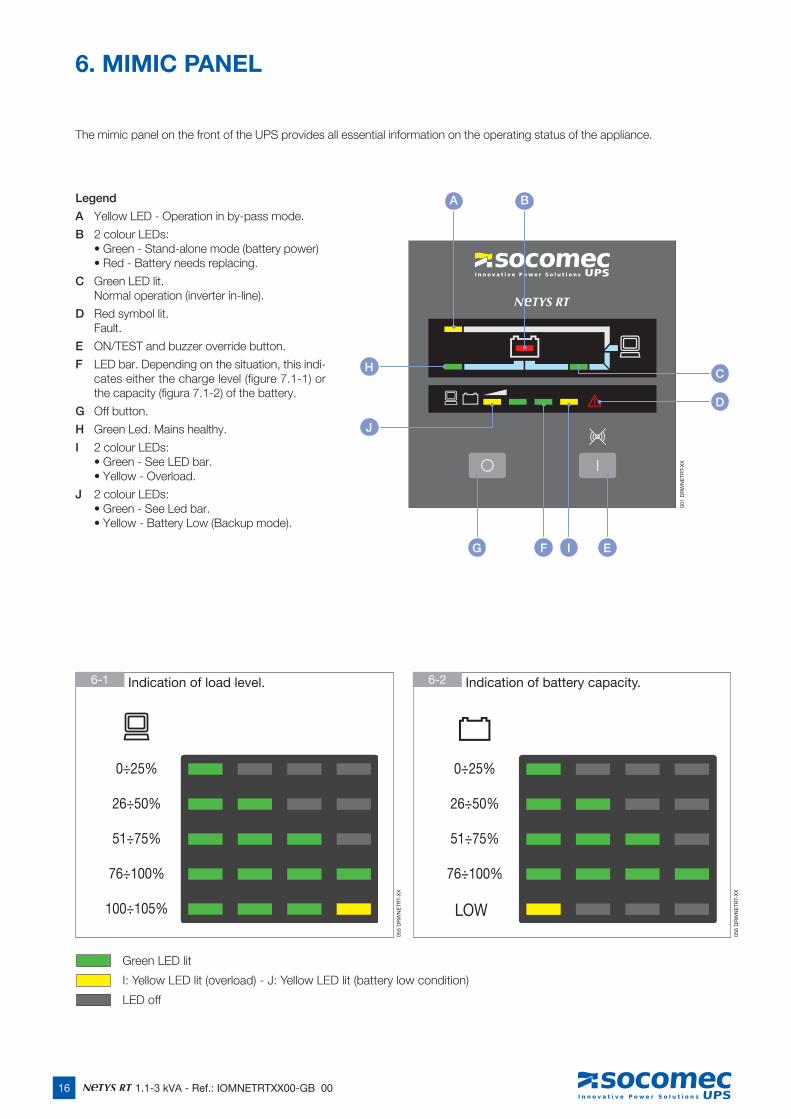
The mimic panel on the front of the UPS provides all essential information on the operating status of the appliance.
6. MIMIC PANEL
G E
A
H
J
B
F I
D
C
0÷25%
26÷50%
51÷75%
76÷100%
100÷105%
0÷25%
26÷50%
51÷75%
76÷100%
Legend
A Yellow LED - Operation in by-pass mode.
B 2 colour LEDs: • Green - Stand-alone mode (battery power) • Red - Battery needs replacing.
C Green LED lit. Normal operation (inverter in-line).
D Red symbol lit. Fault.
E ON/TEST and buzzer override button.
F LED bar. Depending on the situation, this indi-cates either the charge level (figure 7.1-1) or the capacity (figura 7.1-2) of the battery.
G Off button.
H Green Led. Mains healthy.
I 2 colour LEDs: • Green - See LED bar. • Yellow - Overload.
J 2 colour LEDs: • Green - See Led bar. • Yellow - Battery Low (Backup mode).
6-1 Indication of load level. 6-2 Indication of battery capacity.
Green LED lit
I: Yellow LED lit (overload) - J: Yellow LED lit (battery low condition)
LED off
001
DR
WN
ETR
T-X
X
055
DR
WN
ETR
T-X
X
056
DR
WN
ETR
T-X
X
LOW

17 1.1-3 kVA - Ref.: IOMNETRTXX00-GB 00
EN
GLI
SH
3 sec
7.1 Battery recharge
Connect the UPS to the mains voltage for approximately 8 hours to recharge the internal batteries.
The UPS can be used even with the batteries not fully charged, though if a power outage should occur, the duration of the backup will be shorter.
7. OPERATING MODES
3 sec
3 sec
7.1-1
7.2.1-1
7.2.2-1
7.2.1-2
7.2.2-2 Normal operation.
7.2.1-3 Normal operation.
7.2 Switching the Netys RT ON and OFF
7.2.1 Switching on with mains present
7.2.2 Switching on with no mains power
Power up all loads, one at a time.
Power up all loads, one at a time.
141
DR
WN
ETR
T-X
X14
1 D
RW
NE
TRT-
XX
002
DR
WN
ETR
T-X
X
022
DR
WN
ETR
T-X
X00
3 D
RW
NE
TRT-
XX
021
DR
WN
ETR
T-X
X
short
short
short
18 1.1-3 kVA - Ref.: IOMNETRTXX00-GB 00
3 sec
3 sec
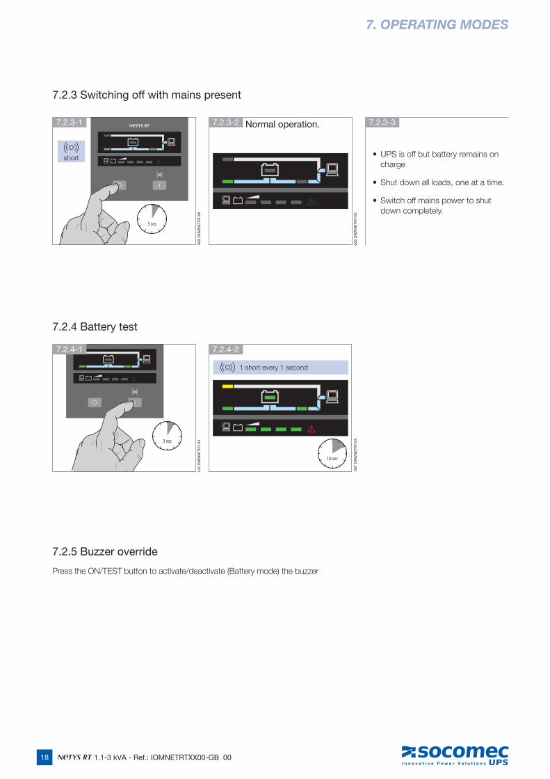
7.2.3 Switching off with mains present
7.2.4 Battery test
7.2.5 Buzzer override
Press the ON/TEST button to activate/deactivate (Battery mode) the buzzer
7. OPERATING MODES
• UPS is off but battery remains on charge
• Shut down all loads, one at a time.
• Switch off mains power to shut down completely.
10 sec
7.2.3-1
7.2.4-1
7.2.3-2 Normal operation.
7.2.4-2
7.2.3-3
short
006
DR
WN
ETR
T-X
X00
7 D
RW
NE
TRT-
XX
008
DR
WN
ETR
T-X
X14
2 D
RW
NE
TRT-
XX
1 short every 1 second
19
EN
GLI
SH
1.1-3 kVA - Ref.: IOMNETRTXX00-GB 00
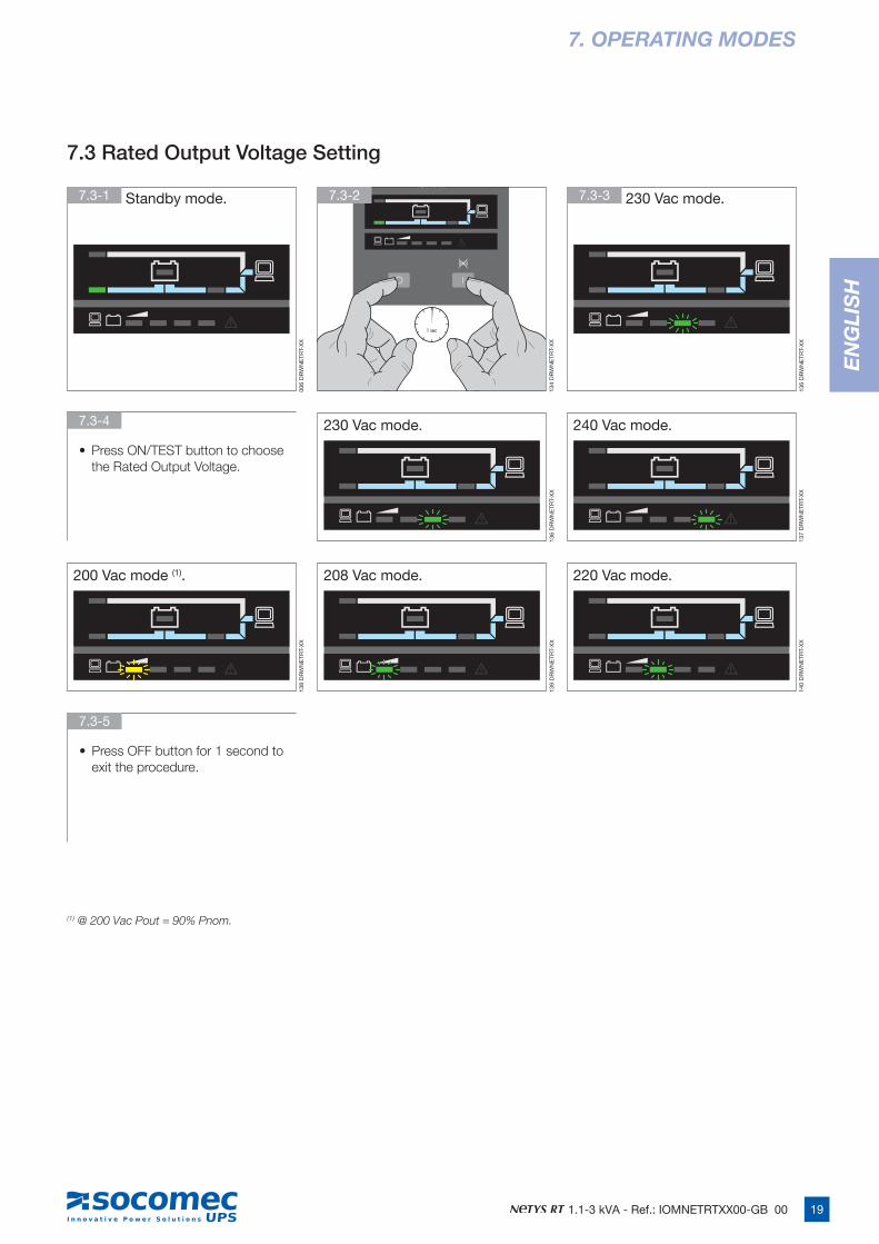
(1) @ 200 Vac Pout = 90% Pnom.
• Press ON/TEST button to choose the Rated Output Voltage.
• Press OFF button for 1 second to exit the procedure.
7.3-1 Standby mode. 7.3-3 230 Vac mode.
230 Vac mode. 240 Vac mode.
200 Vac mode (1). 208 Vac mode. 220 Vac mode.
7.3-2
7.3-4
7.3-5
006
DR
WN
ETR
T-X
X
136
DR
WN
ETR
T-X
X
136
DR
WN
ETR
T-X
X
137
DR
WN
ETR
T-X
X
138
DR
WN
ETR
T-X
X
139
DR
WN
ETR
T-X
X
140
DR
WN
ETR
T-X
X
134
DR
WN
ETR
T-X
X
7. OPERATING MODES
7.3 Rated Output Voltage Setting
1 sec
20 1.1-3 kVA - Ref.: IOMNETRTXX00-GB 00
8. VISUAL AND AUDIBLE WARNING SIGNALS
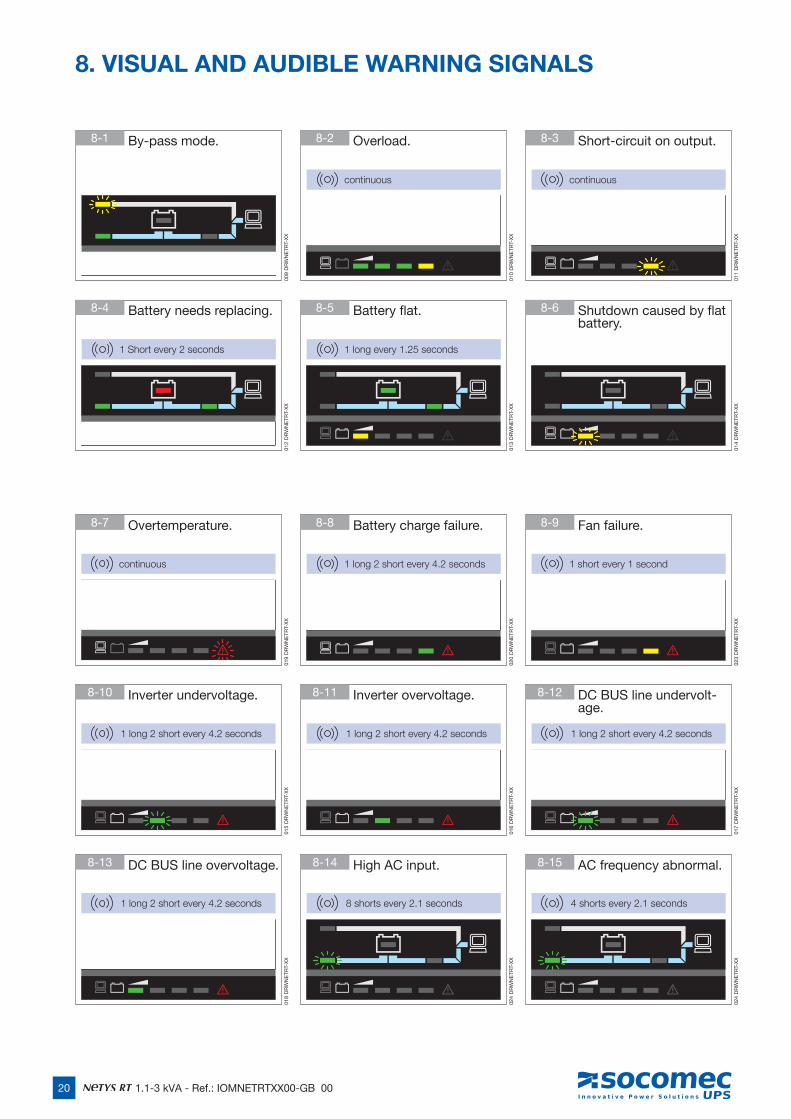
1 long 2 short every 4.2 seconds
continuous 1 long 2 short every 4.2 seconds 1 short every 1 second
1 long 2 short every 4.2 seconds 1 long 2 short every 4.2 seconds
1 long 2 short every 4.2 seconds 8 shorts every 2.1 seconds 4 shorts every 2.1 seconds
1 Short every 2 seconds 1 long every 1.25 seconds
continuous continuous
8-1 By-pass mode.
8-7 Overtemperature.
8-10 Inverter undervoltage.
8-13 DC BUS line overvoltage.
8-4 Battery needs replacing.
8-2 Overload.
8-8 Battery charge failure.
8-11 Inverter overvoltage.
8-14 High AC input.
8-5 Battery flat.
8-3 Short-circuit on output.
8-9 Fan failure.
8-12 DC BUS line undervolt-age.
8-15 AC frequency abnormal.
8-6 Shutdown caused by flat battery.
009
DR
WN
ETR
T-X
X01
2 D
RW
NE
TRT-
XX
019
DR
WN
ETR
T-X
X01
5 D
RW
NE
TRT-
XX
018
DR
WN
ETR
T-X
X
010
DR
WN
ETR
T-X
X01
3 D
RW
NE
TRT-
XX
020
DR
WN
ETR
T-X
X01
6 D
RW
NE
TRT-
XX
024
DR
WN
ETR
T-X
X
011
DR
WN
ETR
T-X
X01
4 D
RW
NE
TRT-
XX
023
DR
WN
ETR
T-X
X01
7 D
RW
NE
TRT-
XX
024
DR
WN
ETR
T-X
X
21
EN
GLI
SH
1.1-3 kVA - Ref.: IOMNETRTXX00-GB 00
Communication software and accessories are available for monitoring the status of the UPS, with the end in view of optimizing normal operation and ensuring that shutdown at the end of backup time is managed correctly. Applications allow recording of all power outages and any depletion of battery power so as to enable the activation of an automatic procedure for closing programs in ordered sequence and shutting down the system.
NETYS RT no-break systems are equipped with RS232 and USB serial communication interfaces, and slots for Web/SNMP cards.
9.1 Communication solutions
• UniVision local management software (RS232interface) with local shutdown functions for Windows™ and Linux systems, downloadable free of charge from the Socemec website www.socomec.com (CD included with certain models).
• Uni Vision Pro network management software (RS232interface) with local/remote shutdown functions on major operating systems, using Java Shutdown Client.
• Web/SNMP manager (Web/SNMP slot card) allowing control via LAN using TCP/IP protocol, and remote shutdown manage-ment.
• BMS (Protocollo JBUS), allows the UPS to interface with a Building Management system.
9.2 USB interface
The UPS can communicate with the server direct by way of the USB interface using HID protocol, if available on the computer operating system, without the need to install any additional software. Once connected, recognition of the UPS occurs in the same way as for any other peripheral, and the operating parameters can be managed by way of the OS service menu. Use the connecting cable provided.
9.3 RS232 interface
This interface is required to run the UniVision local management software and UniVision Pro network management software. Use the cable provided.
9.4 WEB/SNMP card
With this card installed, the UPS can be connected directly to a LAN (RJ45 ethernet) and controlled remotely from a WEB browser using TCP/IP protocol. Reference should be made to the dedicated literature for a full description of the functionalities.
9.5 Use of warning relay interface
This is an optional card (slot-mounted) that will manage 6 indication circuits with isolated contacts carrying information on the status of the UPS. The maximum voltage that can be applied to the contacts is 24 VDC, and the maximum current 500 mA.
Relay contacts can be set individually for NO (default) or NC operation, and programmed selectively for customized monitoring of the UPS.
If requested, the UPS can also be switched off utilizing a remote external shutdown contact. The command is acknowledged when the contact is made and held for 3 seconds (default), whereas the external contact must be made between the common and input pins.
The external contact MUST be dedicated and voltage-free, so as not to cause permanent damage to the UPS.
The shutdown input can be configured alternatively as a battery test input.
9. COMMUNICATION
22 1.1-3 kVA - Ref.: IOMNETRTXX00-GB 00
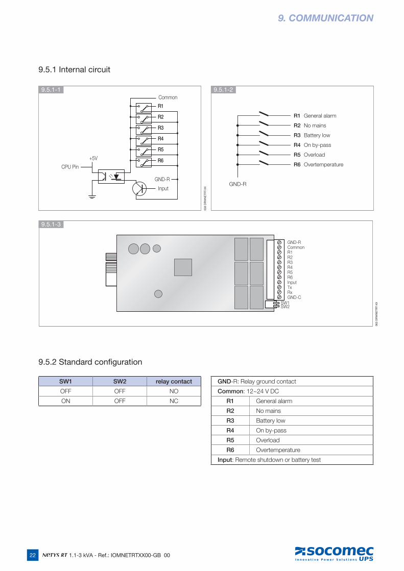
9.5.1 Internal circuit
9.5.2 Standard configuration
9. COMMUNICATION
R1
R2
R3
R4
R5
Common
GND-R
Input
+5V
CPU PinR6
GND-RCommonR1R2R3R4R5R6InputTxRxGND-C
SW1SW2
GND-R
R1 General alarm
R2 No mains
R3 Battery low
R4 On by-pass
R5 Overload
R6 Overtemperature
9.5.1-1
9.5.1-3
9.5.1-2
SW1 SW2 relay contact
OFF OFF NO
ON OFF NC
GND-R: Relay ground contact
Common: 12~24 V DC
R1 General alarm
R2 No mains
R3 Battery low
R4 On by-pass
R5 Overload
R6 Overtemperature
Input: Remote shutdown or battery test
058
DR
WN
ETR
T-X
X
063
DR
WN
ETR
T-X
X
23 1.1-3 kVA - Ref.: IOMNETRTXX00-GB 00
EN
GLI
SH
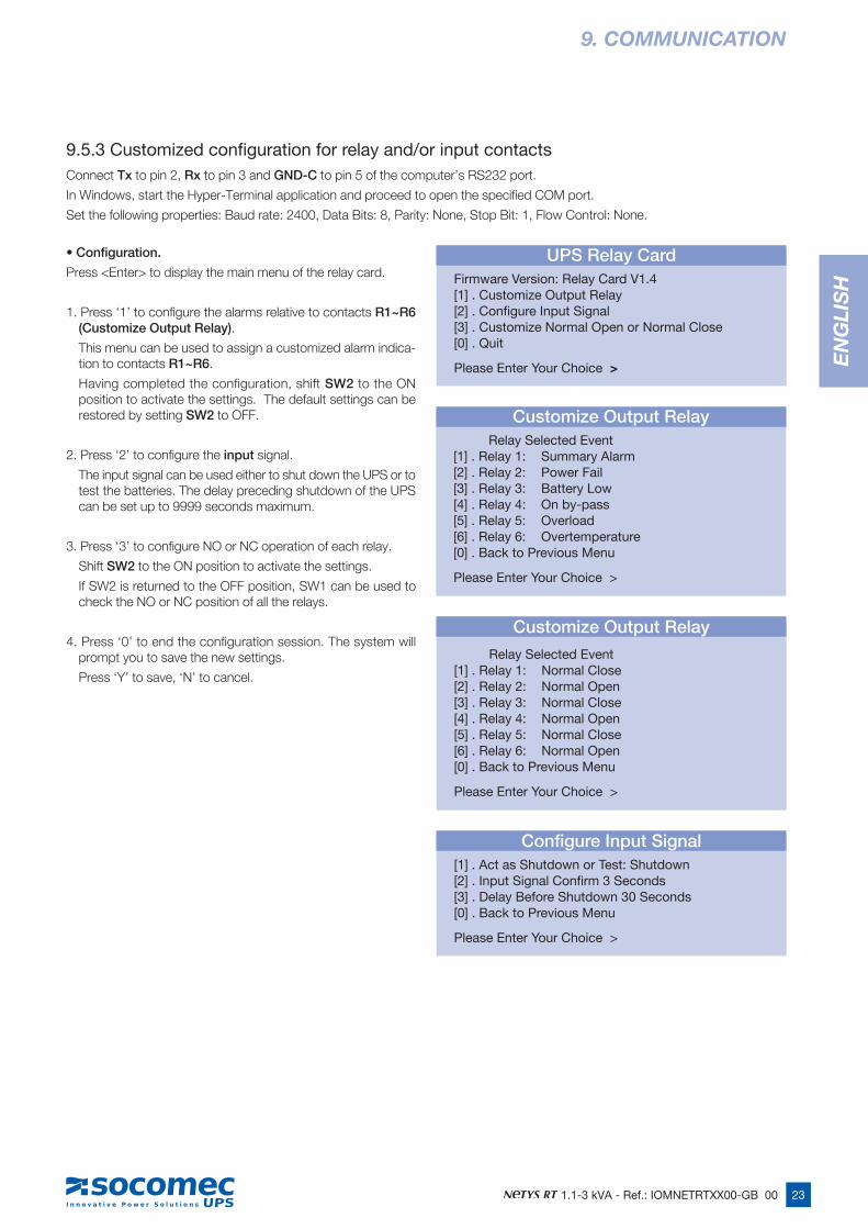
9.5.3 Customized configuration for relay and/or input contactsConnect Tx to pin 2, Rx to pin 3 and GND-C to pin 5 of the computer’s RS232 port.
In Windows, start the Hyper-Terminal application and proceed to open the specified COM port.
Set the following properties: Baud rate: 2400, Data Bits: 8, Parity: None, Stop Bit: 1, Flow Control: None.
9. COMMUNICATION
• Configuration.
Press <Enter> to display the main menu of the relay card.
1. Press ‘1’ to configure the alarms relative to contacts R1~R6 (Customize Output Relay).
This menu can be used to assign a customized alarm indica-tion to contacts R1~R6.
Having completed the configuration, shift SW2 to the ON position to activate the settings. The default settings can be restored by setting SW2 to OFF.
2. Press ‘2’ to configure the input signal.
The input signal can be used either to shut down the UPS or to test the batteries. The delay preceding shutdown of the UPS can be set up to 9999 seconds maximum.
3. Press ‘3’ to configure NO or NC operation of each relay.
Shift SW2 to the ON position to activate the settings.
If SW2 is returned to the OFF position, SW1 can be used to check the NO or NC position of all the relays.
4. Press ‘0’ to end the configuration session. The system will prompt you to save the new settings.
Press ‘Y’ to save, ‘N’ to cancel.
UPS Relay Card Firmware Version: Relay Card V1.4 [1] . Customize Output Relay[2] . Configure Input Signal[3] . Customize Normal Open or Normal Close[0] . Quit
Please Enter Your Choice >
Configure Input Signal [1] . Act as Shutdown or Test: Shutdown[2] . Input Signal Confirm 3 Seconds[3] . Delay Before Shutdown 30 Seconds[0] . Back to Previous Menu
Please Enter Your Choice >
Customize Output Relay Relay Selected Event[1] . Relay 1: Summary Alarm[2] . Relay 2: Power Fail[3] . Relay 3: Battery Low[4] . Relay 4: On by-pass[5] . Relay 5: Overload[6] . Relay 6: Overtemperature[0] . Back to Previous Menu
Please Enter Your Choice >
Customize Output Relay
Relay Selected Event[1] . Relay 1: Normal Close[2] . Relay 2: Normal Open[3] . Relay 3: Normal Close[4] . Relay 4: Normal Open[5] . Relay 5: Normal Close[6] . Relay 6: Normal Open[0] . Back to Previous Menu
Please Enter Your Choice >
24 1.1-3 kVA - Ref.: IOMNETRTXX00-GB 00
10. MAINTENANCE
WARNING! The UPS generates HAZARDOUS INTERNAL VOLTAGES. All maintenance operations should be carried out by AUTHORIZED SERVICE ENGINEERS ONLY.
• The unit will operate to its maximum capability if kept powered up round the clock (24/7); this ensures that the batteries will always be properly charged.
• If the appliance is to remain idle for any length of time, wait until the batteries are fully charged (connection to mains power supply for 8 hours continuous) before shutting the UPS down.
• Recharge the batteries for a duration of 24 hours at least every 4 weeks during the time the unit remains idle.
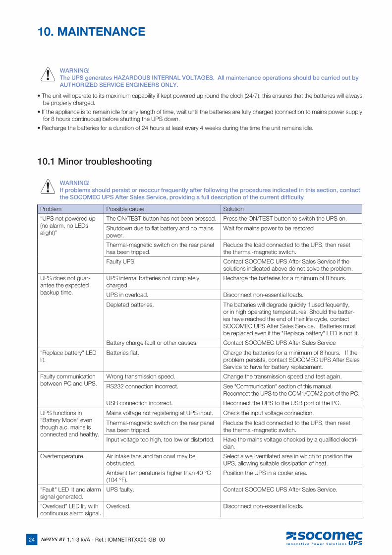
10.1 Minor troubleshooting
WARNING! If problems should persist or reoccur frequently after following the procedures indicated in this section, contact the SOCOMEC UPS After Sales Service, providing a full description of the current difficulty
Problem Possible cause Solution
"UPS not powered up (no alarm, no LEDs alight)”
The ON/TEST button has not been pressed. Press the ON/TEST button to switch the UPS on.
Shutdown due to flat battery and no mains power.
Wait for mains power to be restored
Thermal-magnetic switch on the rear panel has been tripped.
Reduce the load connected to the UPS, then reset the thermal-magnetic switch.
Faulty UPS Contact SOCOMEC UPS After Sales Service if the solutions indicated above do not solve the problem.
UPS does not guar-antee the expected backup time.
UPS internal batteries not completely charged.
Recharge the batteries for a minimum of 8 hours.
UPS in overload. Disconnect non-essential loads.
Depleted batteries. The batteries will degrade quickly if used fequently, or in high operating temperatures. Should the batter-ies have reached the end of their life cycle, contact SOCOMEC UPS After Sales Service. Batteries must be replaced even if the "Replace battery" LED is not lit.
Battery charge fault or other causes. Contact SOCOMEC UPS After Sales Service
"Replace battery" LED lit.
Batteries flat. Charge the batteries for a minimum of 8 hours. If the problem persists, contact SOCOMEC UPS After Sales Service to have for battery replacement.
Faulty communication between PC and UPS.
Wrong transmission speed. Change the transmission speed and test again.
RS232 connection incorrect. See "Communication" section of this manual. Reconnect the UPS to the COM1/COM2 port of the PC.
USB connection incorrect. Reconnect the UPS to the USB port of the PC.
UPS functions in "Battery Mode" even though a.c. mains is connected and healthy.
Mains voltage not registering at UPS input. Check the input voltage connection.
Thermal-magnetic switch on the rear panel has been tripped.
Reduce the load connected to the UPS, then reset the thermal-magnetic switch.
Input voltage too high, too low or distorted. Have the mains voltage checked by a qualified electri-cian.
Overtemperature. Air intake fans and fan cowl may be obstructed.
Select a well ventilated area in which to position the UPS, allowing suitable dissipation of heat.
Ambient temperature is higher than 40 °C (104 °F).
Position the UPS in a cooler area.
"Fault" LED lit and alarm signal generated.
UPS faulty. Contact SOCOMEC UPS After Sales Service.
"Overload" LED lit, with continuous alarm signal.
Overload. Disconnect non-essential loads.
25
EN
GLI
SH
1.1-3 kVA - Ref.: IOMNETRTXX00-GB 00
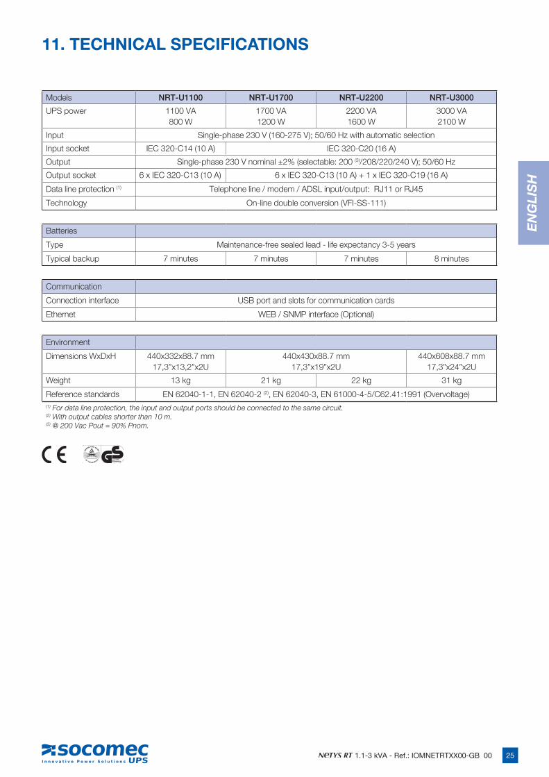
11. TECHNICAL SPECIFICATIONS
Models NRT-U1100 NRT-U1700 NRT-U2200 NRT-U3000
UPS power 1100 VA800 W
1700 VA1200 W
2200 VA1600 W
3000 VA2100 W
Input Single-phase 230 V (160-275 V); 50/60 Hz with automatic selection
Input socket IEC 320-C14 (10 A) IEC 320-C20 (16 A)
Output Single-phase 230 V nominal ±2% (selectable: 200 (3)/208/220/240 V); 50/60 Hz
Output socket 6 x IEC 320-C13 (10 A) 6 x IEC 320-C13 (10 A) + 1 x IEC 320-C19 (16 A)
Data line protection (1) Telephone line / modem / ADSL input/output: RJ11 or RJ45
Technology On-line double conversion (VFI-SS-111)
Batteries
Type Maintenance-free sealed lead - life expectancy 3-5 years
Typical backup 7 minutes 7 minutes 7 minutes 8 minutes
Communication
Connection interface USB port and slots for communication cards
Ethernet WEB / SNMP interface (Optional)
Environment
Dimensions WxDxH 440x332x88.7 mm17,3”x13,2”x2U
440x430x88.7 mm17,3”x19”x2U
440x608x88.7 mm17,3”x24”x2U
Weight 13 kg 21 kg 22 kg 31 kg
Reference standards EN 62040-1-1, EN 62040-2 (2), EN 62040-3, EN 61000-4-5/C62.41:1991 (Overvoltage)(1) For data line protection, the input and output ports should be connected to the same circuit.(2) With output cables shorter than 10 m.(3) @ 200 Vac Pout = 90% Pnom.
Non contractual document. © 2008, Socomec SA. All rights reserved.
H E A D O F F I C ESOCOMEC GROUPS.A. SOCOMEC capital 11 102 300 € - R.C.S. Strasbourg B 548 500 149B.P. 60010 - 1, rue de Westhouse - F-67235 Benfeld CedexSOCOMEC UPS Strasbourg11, route de Strasbourg - B.P. 10050 - F-67235 Huttenheim Cedex- FRANCETel. +33 (0)3 88 57 45 45 - Fax +33 (0)3 88 74 07 [email protected] UPS Isola VicentinaVia Sila, 1/3 - I - 36033 Isola Vicentina (VI) - ITALYTel. +39 0444 598611 - Fax +39 0444 [email protected]
S A L E S , M A R K E T I N G A N D S E R V I C E M A N A G E M E N T
SOCOMEC UPS Paris95, rue Pierre GrangeF-94132 Fontenay-sous-Bois Cedex - FRANCETel. +33 (0)1 45 14 63 90 - Fax +33 (0)1 48 77 31 [email protected]
Socomec UPSworldwideI N E U R O P E
BELGIUMSchaatsstraat, 30 rue du PatinageB - 1190 BruxellesTel. +32 (0)2 340 02 34Fax +32 (0)2 346 16 [email protected]
FRANCE95, rue Pierre GrangeF - 94132 Fontenay-sous-Bois CedexTel. +33 (0)1 45 14 63 90 Fax +33 (0)1 48 77 31 [email protected]
GERMANYHeppenheimerstraße 57D - 68309 MannheimTel. +49 (0) 621 71 68 40Fax +49 (0) 621 71 68 44 [email protected]
ITALYVia Leone Tolstoi, 73 - Zivido20098 San Giuliano Milanese (MI)Tel. +39 02 98 242 942Fax +39 02 98 240 [email protected]
NETHERLANDSBergveste 2FNL - 3992DE HoutenTel. +31 (0)30 63 71 504Fax +31 (0)30 63 72 [email protected]
POLANDNowowiejska St 21/25 00-665 Warszawa Tel. +48 (0)22 2345 223 Fax +48 (0)22 2345 223 [email protected]
PORTUGALRua Moinho do CucoBloco ALj. Dta. - Paz2640-566 MAFRATel. +351 261 812 599Fax +351 261 812 [email protected]
RUSSIAKutuzovsky pr. 13, 44-45121248 - MoscowTel. +7 495 775 19 85Fax +7 495 775 19 [email protected]
SLOVENIASavlje 89SI - 1000 LjubljanaTel. +386 1 5807 860Fax +386 1 5611 [email protected]
SPAINC/Nord, 22 Pol. Ind. BuvisaE - 08329 Teià (Barcelona)Tel. +34 935 407 575Fax +34 935 407 [email protected]
UNITED KINGDOMUnits 7-9 Lakeside Business ParkBroadway Lane - South Cerney Cirencester - GL7 5XLTel. +44 (0)1285 863300Fax +44 (0)1285 [email protected]
I N A S I A
CHINANo.1 Yuanda Road Haidian District, Beijing, 100097Golden Resource Times Shopping MallNo. 1001 section B the 2nd issue of business buildingTel. +86 10 8889 2202Fax +86 10 8889 [email protected]
INDIAB1, IInd Floor, Thiru-Vi-Ka-Industrial EstateGuindyChennai – 600 032Tel. +91 44 3921 5400 Fax +91 44 3921 5450 — [email protected]
MALAYSIA31 Jalan SS 25/41- Mayang Industrial Park47301 Petaling Jaya.- Selangor, MalaysiaTel. +603 7804 1153Fax +603 7803 [email protected]
SINGAPORE 31 Ubi Road 1, Aztech Building# 01-00 (Annex) - SG - Singapore 408694Tel. +65 6745 7555Fax +65 6458 [email protected]
THAILANDNo.9 Soi Vibhavadirangsit 42 Vibhavadirangsit Rd, Ladyao Chatujak Bangkok 10900Tel. +66 2 941-1644-7Fax. +66 2 [email protected]
www.socomec.com
Valid for France Valid for Italy
*IOMNETRTXX00-GB 00*IOMNETRTXX00-GB 00 01.2009