Embed Size (px)
Citation preview
11
An Overview of Claus Offerings from Axens
2
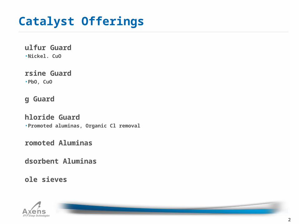
Sulfur Guard• Nickel. CuO
Arsine Guard• PbO, CuO
Hg Guard
Chloride Guard• Promoted aluminas, Organic Cl removal
Promoted Aluminas
Adsorbent Aluminas
Mole sieves
Catalyst Offerings
3
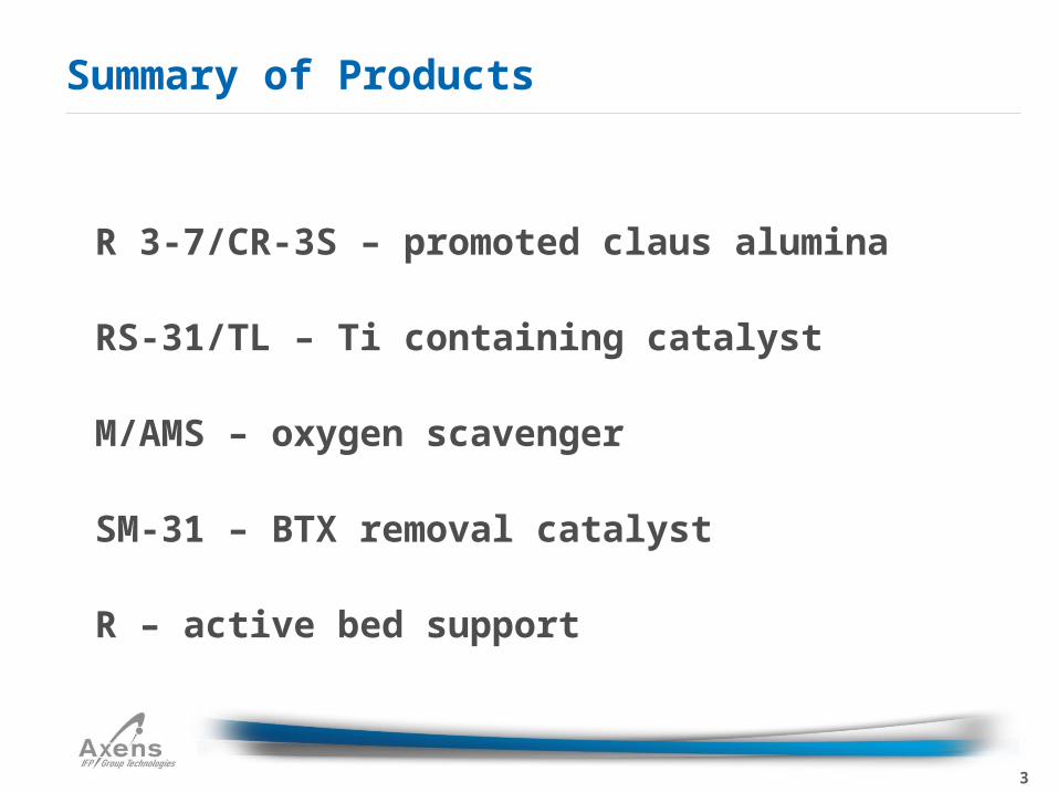
CR 3-7/CR-3S – promoted claus alumina
CRS-31/TL – Ti containing catalyst
AM/AMS – oxygen scavenger
CSM-31 – BTX removal catalyst
DR – active bed support
Summary of Products
4
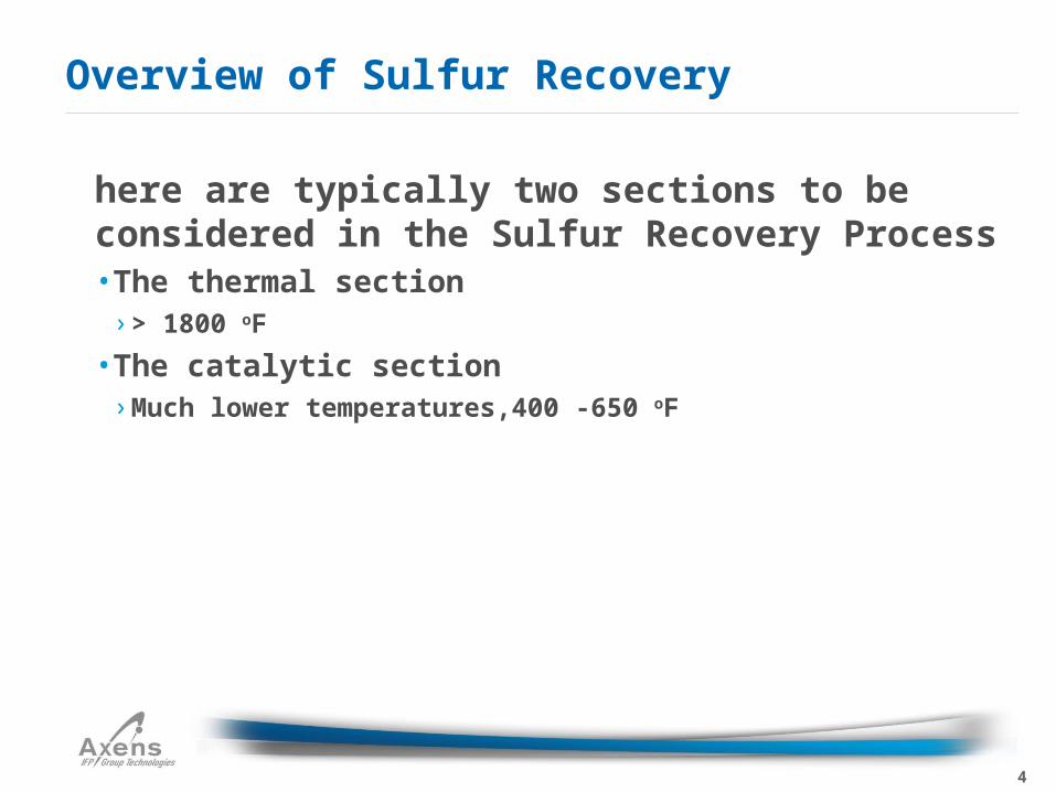
There are typically two sections to be considered in the Sulfur Recovery Process• The thermal section
› > 1800 oF
• The catalytic section› Much lower temperatures,400 -650 oF
Overview of Sulfur Recovery
5
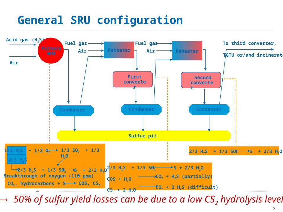
General SRU configuration
2/3 H2S + 1/3 SO2
COS + H2O
CS2 + 2 H2O
S + 2/3 H2O
CO2 + H2S (partially)
CO2 + 2 H2S (difficult)
2/3 H2S + 1/3 SO2 S + 2/3 H2O1/3 SO2 + 1/3 H2O
2/3 H2S + 1/3 SO2 S + 2/3 H2O
CO2, hydrocarbons + S COS, CS2
2/3 H2S
Breakthrough of oxygen (110 ppm)
1/3 H2S + 1/2 O2
50% of sulfur yield losses can be due to a low CS2 hydrolysis level!
Acid gas (H2S)
Air
FurnaceWHB
Reheater
Condenser Condenser Condenser
Reheater
Fuel gas
AirAir
Fuel gas To third converter,
TGTU or/and incinerator
Sulfur pit
Firstconverte
r
Secondconverter
6
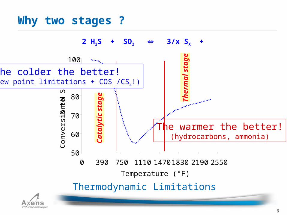
Why two stages ?
Thermodynamic Limitations
2 H2S + SO2 3/x SX + 2 H2O
50
60
70
80
90
100
0 390 750 1110 1470 1830 2190 2550
Temperature (°F)
Con
vers
ion
H
2 S to
S (
%)
.
Cat
alyt
ic s
tage
.
Th
erm
al s
tage
.
The colder the better!(but dew point limitations + COS /CS2!)
The warmer the better!(hydrocarbons, ammonia)
7
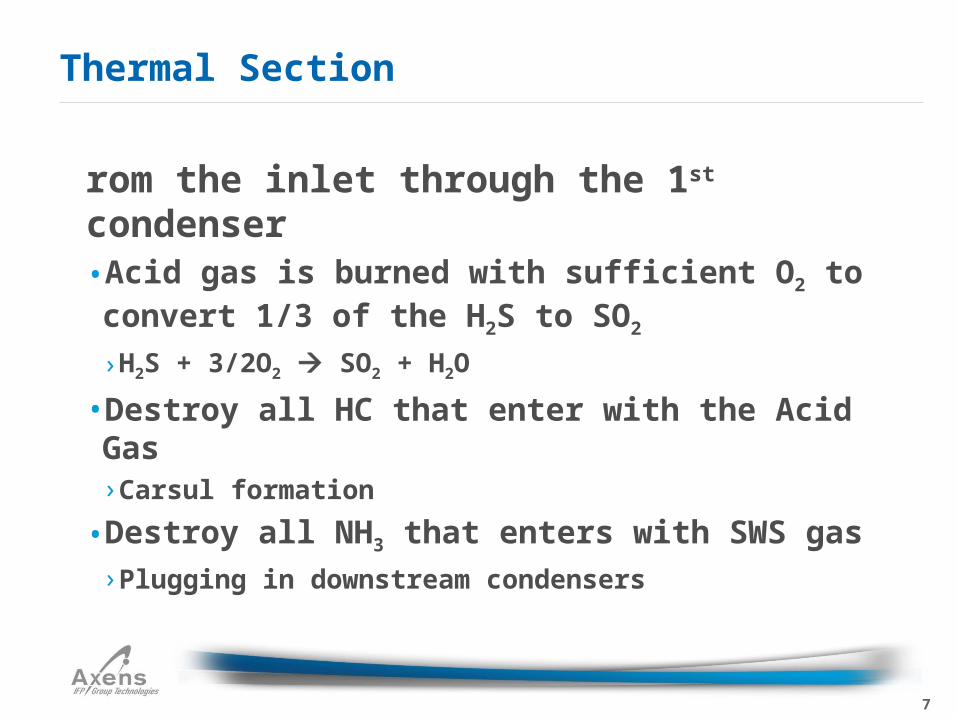
From the inlet through the 1st condenser• Acid gas is burned with sufficient O2 to convert 1/3 of the H2S to SO2
› H2S + 3/2O2 SO2 + H2O
• Destroy all HC that enter with the Acid Gas› Carsul formation
• Destroy all NH3 that enters with SWS gas› Plugging in downstream condensers
Thermal Section
8
Refineries typically run rich acid gas streams• 70 – 90 % H2S
Gas plants typically run lean acid gas streams• < 50 % H2S
• Requires different configuration and will not be coveredO
ptions to increase Reactor Furnace temperature• O2 enrichment, increase through put and destroy incoming contaminants
Thermal Section
9
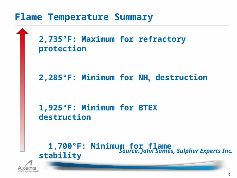
Flame Temperature Summary
2,735°F: Maximum for refractory protection
2,285°F: Minimum for NH3 destruction
1,925°F: Minimum for BTEX destruction
1,700°F: Minimum for flame stability
Source: John Sames, Sulphur Experts Inc.
10
Hydrocarbons• If not destroyed in the reaction furnace can lead to the formation of Carsuls, results in Delta P issues and rapid deactivation of Claus
• HC + S CS2
• CS2 must be destroyed in the first converter
Thermal Section
11
Excess CO2• CO2 + S COS• COS must be destroyed in the first converter
Thermal Section
12
SWS Gas• NH3 needs to be converted in the reaction furnace (> 2300 oF)
• Leads to NH3 salts which will deposit in condensers, resulting in Delta P issues
Thermal Section
13
Oxidation Reaction› H2S + 3/2O2 SO2 + H2O
•This sets up the standard Claus Reaction of a 2 to 1 ratio› With TGU ratio could be increased to 3 -1, or even 4-1 to reduce load on TGU
•Endothermic› 2H2S + SO2 3/2S2 + 2H2O
•60 - 70% of the sulfur is removed in the first condenser after the Reaction Furnace
•Generates medium pressure steam (450–600 #)
Thermal Section
14
Typical operating schemes• Re-heat, catalytic bed, condenser for sulfur recovery• 2nd Converter
› Inlet Temperature 410-420 oF, outlet 460 oF
• 3rd Converter› Inlet Temperature 395-400 oF, outlet 400-430 oF
• Inlet temperatures are typically 15-20 oF above dew point of Sulfur
• Too high outlet temperature from condensers will result in Sulfur carry over
Catalytic Section
15
2 Converter system will result in Sulfur recovery of 96 %
3 Converter system can be 97-98 % Sulfur recovery
Catalytic Section
16
Remove the unrecovered sulfur from the first condenser• Claus reaction aided by Claus catalyst
› Alumina, Titania, specialty catalysts
• Consists of three steps› Re-heating, conversion, cooling/condensing
• Typically first converter is run hot (450-480 oF inlet) to remove COS and CS2
Highly exothermic
Catalytic Section
17
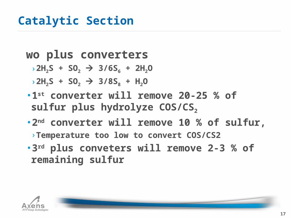
Two plus converters
› 2H2S + SO2 3/6S6 + 2H2O
› 2H2S + SO2 3/8S8 + H2O
• 1st converter will remove 20-25 % of sulfur plus hydrolyze COS/CS2
• 2nd converter will remove 10 % of sulfur,› Temperature too low to convert COS/CS2
• 3rd plus conveters will remove 2-3 % of remaining sulfur
Catalytic Section
18
Because of large S6-8 molecules, maximum macro-porosity is required to reduce diffusion limitations
Catalytic Section
19
Alumina Selection Physical Characteristics
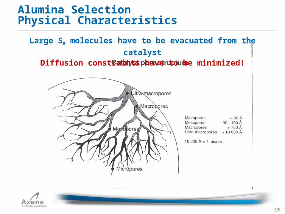
Large S8 molecules have to be evacuated from the catalyst
Diffusion constraints have to be minimized!
20
CR 3-7• This alumina catalyst is for standard Claus feeds where the
basic priorities are simple conversion of H2S and when low pressure drop requirements are imposed. This low-cost catalyst is attractive when there are no particular processing constraints.
• Equivalent to all competitive standard Claus catalyst on the market
• Available in ¼” and 3/16” sizes
• Surface Area = 285-350 m2/g
• Excellent abrasion resistance
• Low Density (39 lbs/cu ft)
• Macroporosity (>750 Å) = .224 ml/g, the highest in the industry
Claus Alumina for Better Performance
21
CR-3S Physico-chemical Optimization
37
42
47
52
57
62
67
72
0 800 1600 2400 3200 4000
Na2O (ppm)
Con
vers
ion
(%)
.
Claus, R2
CS2, R1
Diffusional constraints Activity-deactivation10 ppm O2, = 2s, Na2O = 2000 ppm 10(500) ppm O2 in R1(R2), = 2s, V0.1 = 16
The truth between constraints minimisation and compromises.
CR-3S combines both physical and chemical optimizations.
CS2 Conversion, %
0.3 0.4 0.5 0.6 0.7 0.8 0.9
52
48
44
40
36
Ratio of Ultra Macroporosity to Macroporosity, V1 / V0.1
Range forBestCompetitiveAluminas
V1 = Volume of pores greater than 1 µmV0.1 = Volume of pores greater than 0.1 µm
Constant macroporosity
V0.1= 20 ml/100 g
Constant macroporosity
V0.1= 16 ml/100 g
Range for CR 3SP
atented
22
Operate with an inlet temperature of 450 – 480 oF• Hydrolysis of COS/CS2 which requires a higher temperature
• Important from a Sulfur Recovery perspective• Reduce load on TGU• Outlet temperature of 580-630 oF
1st Converter
23
If you can provide us with Reaction Furnace inlet or outlet concentrations from 1st condenser, we can design a catalyst system that will give you optimum performance.
COS/CS2
24
COS/CS2 hydrolysis
• 50-70% conversion of CS2 with standard aluminas or hybrid Ti catalysts
• 95-100% hydrolysis of CS2 with CRS-31, a high Ti containing catalyst› Outlet temperature can be reduced to 570-590 oF
Reduced operating costs
• CS2 is the most difficult of these two species to hydrolyze in the first converter
• COS 80-90 % with standard aluminas or hybrid TI• COS 100 % hydrolyzed with CRS-31• Reduce demand on TGU plus reduce SO2 emissions
1st Converter
25
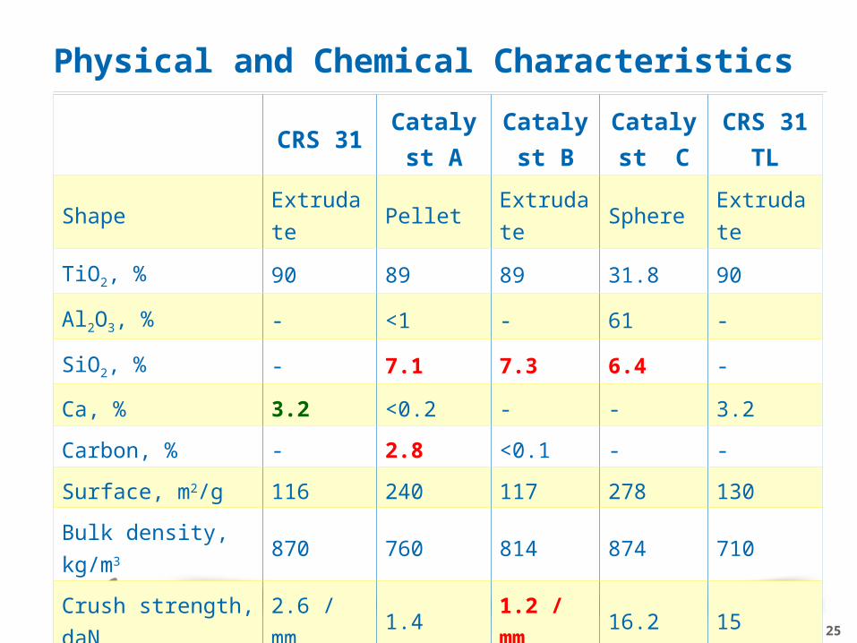
CRS 31Catalyst
A
Catalys
t B
Catalys
t C
CRS 31
TL
Shape Extrudate Pellet Extrudate Sphere Extrudate
TiO2, % 90 89 89 31.8 90
Al2O3, % - <1 - 61 -
SiO2, % - 7.1 7.3 6.4 -
Ca, % 3.2 <0.2 - - 3.2
Carbon, % - 2.8 <0.1 - -
Surface, m2/g 116 240 117 278 130
Bulk density, kg/m3 870 760 814 874 710
Crush strength, daN 2.6 / mm 1.4 1.2 / mm 16.2 15
TPV, ml/100g 29.8 62.0 45.1 41.5 35
Physical and Chemical Characteristics
26
Testing done at ASRL by a Middle East Gas company
Extreme conditions used• High levels of Xylene and Toluene
CRS-31 was tested as the best for CS2 conversion under these conditions
Titania and Alumina-Titania Hybrid Catalysts
27
0102030405060708090
100
0 10 20 30 40 50 60 70 80
% C
S2
Con
vers
ion
Time on Stream (h)
D
CRS-31
CompetitiveHybrid Ti
}B&C
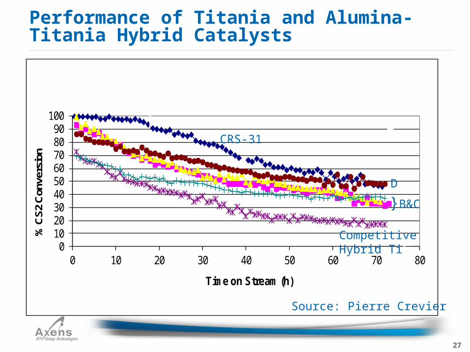
Performance of Titania and Alumina-Titania Hybrid Catalysts
A
DF
E
Performance of Titania and Alumina-Titania Hybrid Catalysts
Source: Pierre Crevier
28
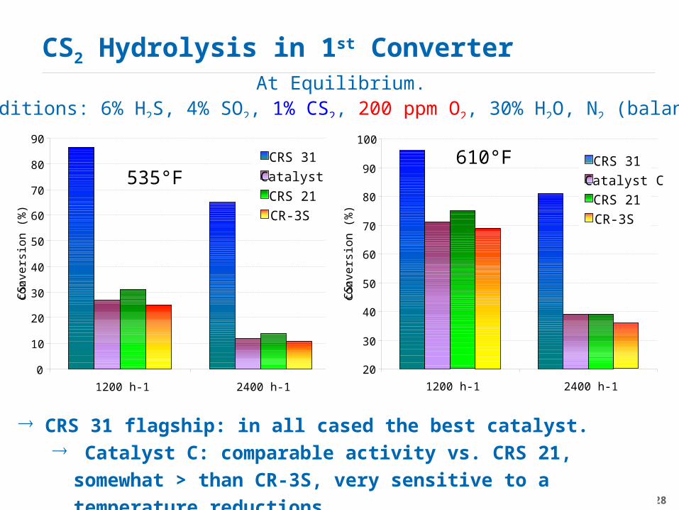
CS2 Hydrolysis in 1st ConverterAt Equilibrium.
Conditions: 6% H2S, 4% SO2, 1% CS2, 200 ppm O2, 30% H2O, N2 (balance)
CRS 31 flagship: in all cased the best catalyst. Catalyst C: comparable activity vs. CRS 21, somewhat > than
CR-3S, very sensitive to a temperature reductions.
0
10
20
30
40
50
60
70
80
90
1200 h-1 2400 h-1
CS
2 con
vers
ion
(%)
.
CRS 31
Catalyst C
CRS 21
CR-3S
535°F
20
30
40
50
60
70
80
90
100
1200 h-1 2400 h-1
CS2
conv
ersi
on (
%)
.
CRS 31
Catalyst C
CRS 21
CR-3S
610°F
29
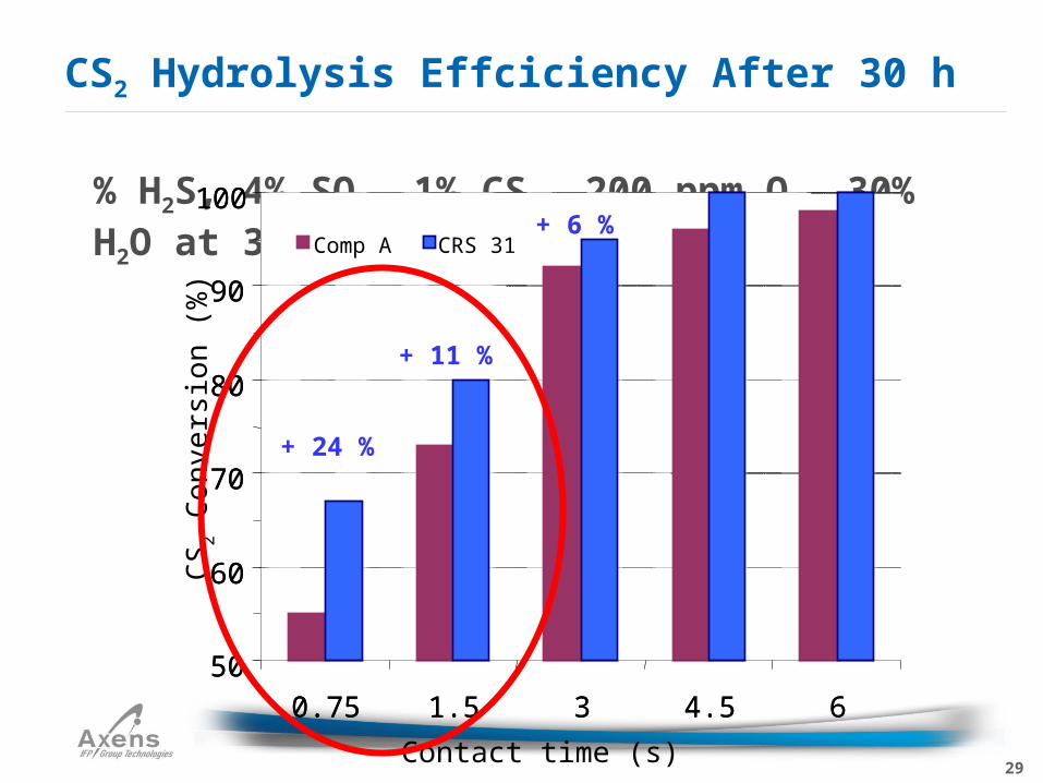
6% H2S, 4% SO2, 1% CS2, 200 ppm O2, 30% H2O at 320°C
CS2 Hydrolysis Effciciency After 30 h
50
60
70
80
90
100
0.75 1.5 3 4.5 6
. S-7001 CRS 31
50
60
70
80
90
100
0.75 1.5 3 4.5 6
Contact time (s)
CS
2 Con
vers
ion
(%)
.
Comp A CRS 31
+ 24 %
+ 11 %
+ 6 %
30
CS2 Hydrolysis (R1)
40
50
60
70
80
90
100
0 15 30 45 60 75
Time (h)
CS
2 hy
drol
ysis
(%)
.
CRS 31
CR-3S
CA1
CA2
40
50
60
70
80
90
100
CS
2 hy
drol
ysis
(%)
.
CRS 31 CR-3S CA1 CA2
200 ppm O2
1500 ppm O2
200 ppm O2, = 3 s = 3 s, at the equilibrium
Superiority of TiO2 over Al2O3: CRS 31 is the most efficient.
Interest of an optimized speciality alumina (Na2O 2000 ppm, V0,1µm > 12 ml/100g with V1µm/V0,1µm > 0.7). CA: competitive alumina.
31
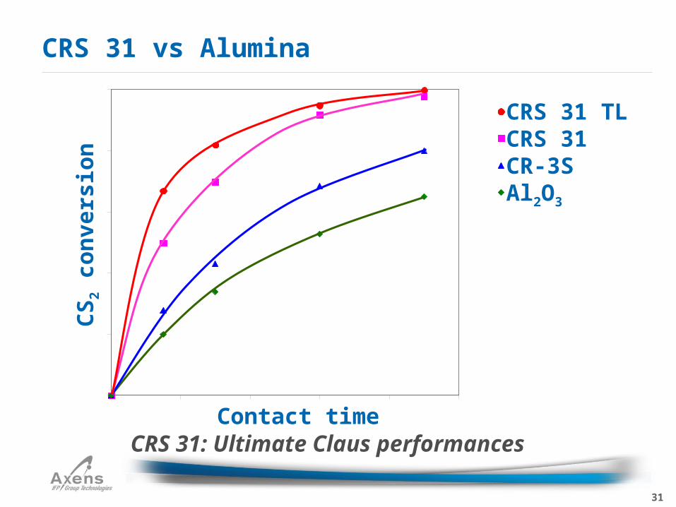
CRS 31 vs Alumina
CRS 31 TLCRS 31CR-3SAl2O3
Contact time
CS
2 c
on
vers
ion
CRS 31: Ultimate Claus performances
32
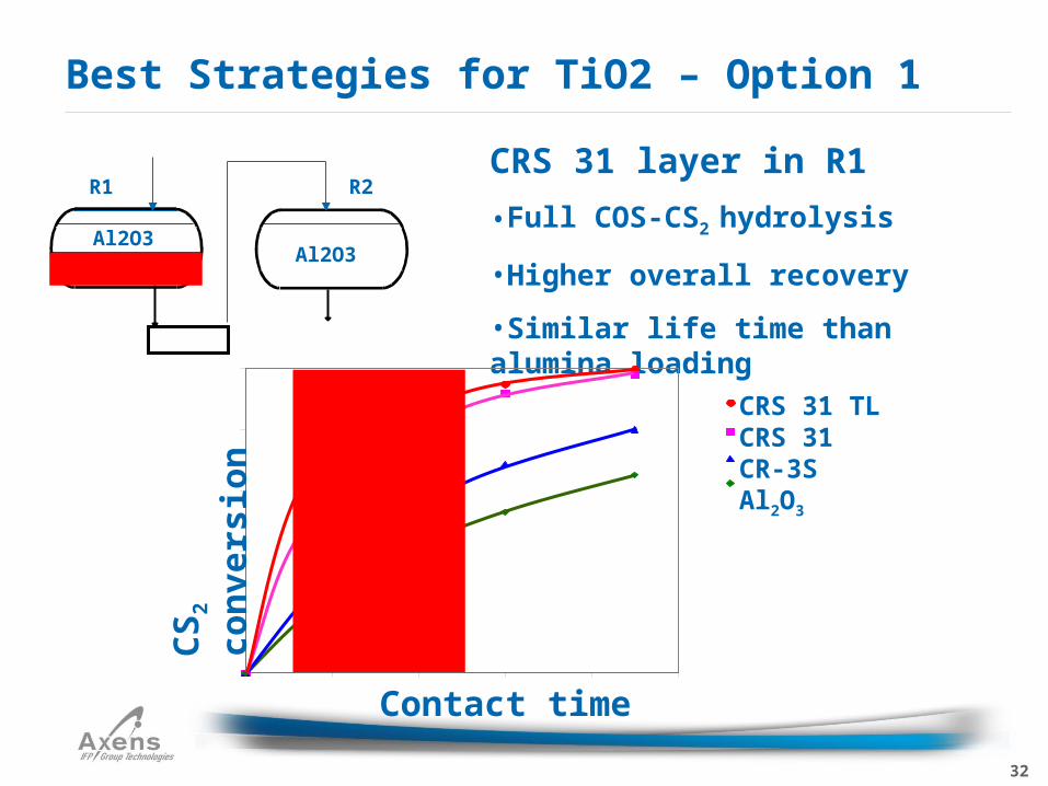
Best Strategies for TiO2 – Option 1
Al2O3
CRS 31Al2O3
R1 R2CRS 31 layer in R1
•Full COS-CS2 hydrolysis
•Higher overall recovery
•Similar life time than alumina loading
Contact time
CRS 31 TLCRS 31CR-3SAl2O3
CS
2 c
on
vers
ion
33
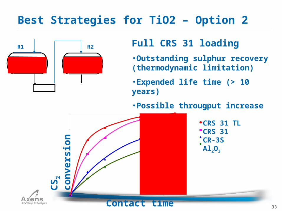
Best Strategies for TiO2 – Option 2
Full CRS 31 loading
•Outstanding sulphur recovery (thermodynamic limitation)
•Expended life time (> 10 years)
•Possible througput increase
CRS 31 CRS 31
R1 R2
Contact time
CRS 31 TLCRS 31CR-3SAl2O3
CS
2 c
on
vers
ion
34
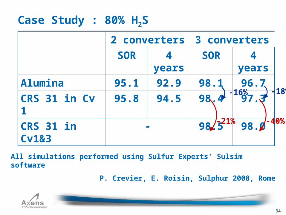
2 converters 3 converters
SOR 4 years SOR 4 years
Alumina 95.1 92.9 98.1 96.7
CRS 31 in Cv 1 95.8 94.5 98.4 97.3
CRS 31 in Cv1&3
- 98.5 98.0
Case Study : 80% H2S
All simulations performed using Sulfur Experts’ Sulsim software
P. Crevier, E. Roisin, Sulphur 2008, Rome
-18%
-40%
-16%
-21%
35
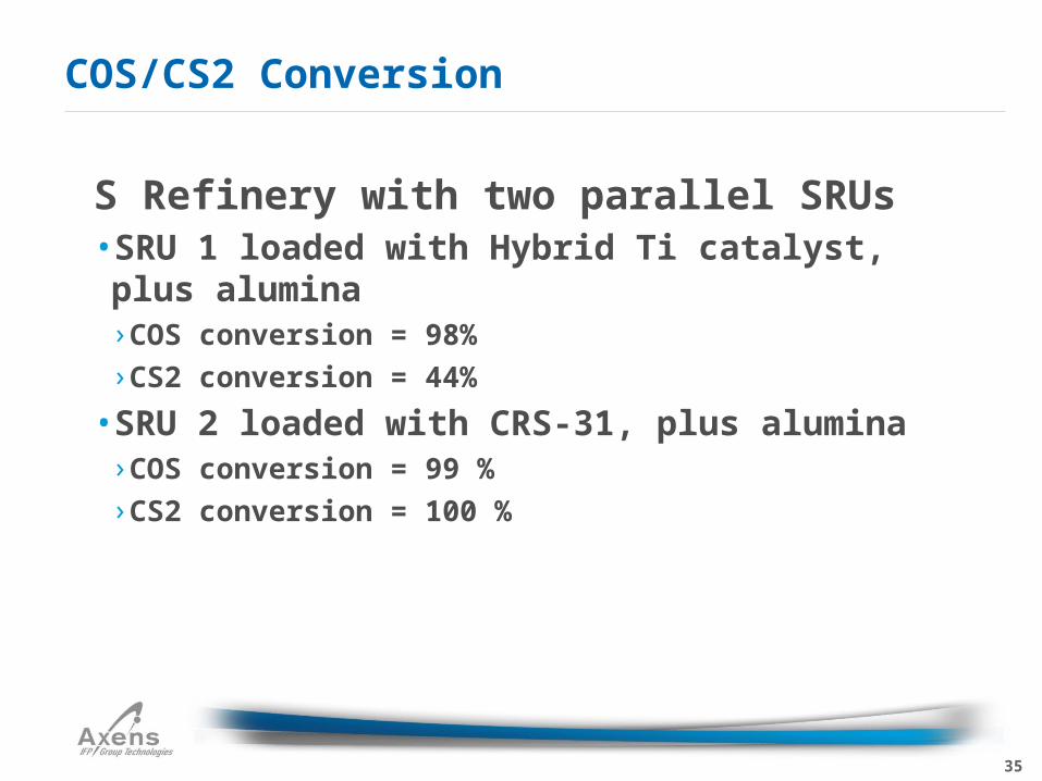
US Refinery with two parallel SRUs• SRU 1 loaded with Hybrid Ti catalyst, plus alumina
› COS conversion = 98%
› CS2 conversion = 44%
• SRU 2 loaded with CRS-31, plus alumina› COS conversion = 99 %
› CS2 conversion = 100 %
COS/CS2 Conversion
36
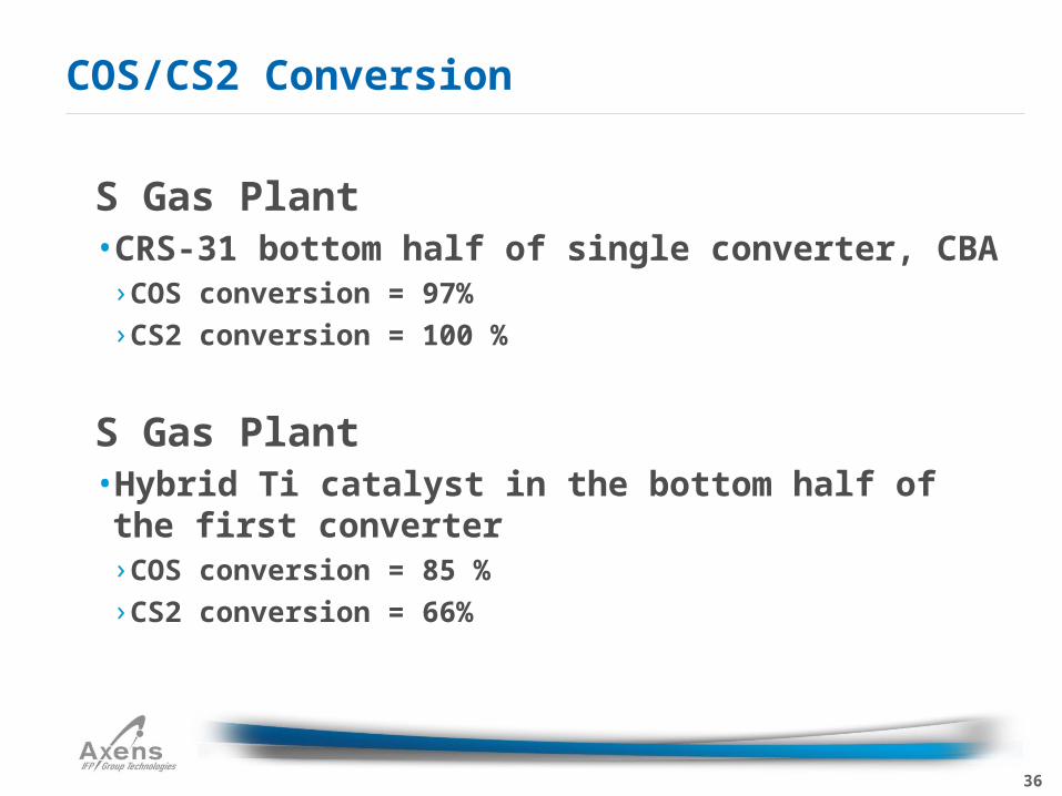
US Gas Plant• CRS-31 bottom half of single converter, CBA
› COS conversion = 97%
› CS2 conversion = 100 %
US Gas Plant• Hybrid Ti catalyst in the bottom half of the first converter› COS conversion = 85 %
› CS2 conversion = 66%
COS/CS2 Conversion
37
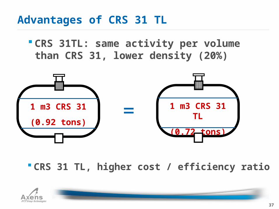
Advantages of CRS 31 TL
1 m3 CRS 31
(0.92 tons)
1 m3 CRS 31 TL
(0.72 tons)=
CRS 31TL: same activity per volume than CRS 31, lower density (20%)
CRS 31 TL, higher cost / efficiency ratio
38
CRS-31 vs. CRS-31 TL
CRS-31 TL = Trilobe, CRS-31 = cylindrical
extrudate
CRS-31 TL density of 44.3 versus CRS-31 density
of 57 lb/cu ft
No difference in performance
70 references on CRS-31 TL showing equivalent
performance
39
Potential Problems• Sulfation of catalyst due to excess O2
› Excess O2 in reaction furnace
› In-line burners, direct re-heat between converters
› This can be eliminated by installing an O2 scavenger in the top of the bed
› Partial correction of problem by increasing H2S in feed and temperature to converters by 35-90 oF for approximately 12 hours
Catalytic Section
40
In-line burners in between converters can result in excess O2 entering the following converter resulting in Sulfation
Excess O2 to reaction furnace
Sulfation
41
Caused by sooting • Due to poor operation of the reaction furnace
Reduced throughput due to High Delta P
This problem can be reversed• Use a Sulfur wash
› Go sub Dew point for a period of time
› Sulfur lays down on the catalyst
› Increase temperature to heat soak levels
› Washes the soot off the catalyst. Reducing the Delta P
› May need to be performed several times in the event of extreme sooting
High Delta P in the 1st Converter
42
Lower the level in the sulfur pit
Shut off the reheater ahead of the converter with abnormally high ΔP
Operate the converter in sub-dew point mode for 12 to 16 hours•Time equivalent to production of sulfur = to ~ ⅓ the fresh catalyst weight
Return reheater to service and perform a heat soak
Expect to see black sulfur and soot to flow through the seal pot
Sulfur Wash Procedure
43
Repeat as necessary until pressure drop has been restored
A badly sooted bed may need two or three washes to remove the majority of carbon fines
This procedure has been practiced successfully by many operators
Sulfur Wash
44
References•Haji, M.N and Adab A.M. “Catalyst sulfur wash: a successful technique to remove soot from Claus catalyst beds online” LRGCC 2001
•Reprinted in Oil & Gas Journal – 11 June, 2001, vol 99.24 p 54-59
•R. Toor and J. Balken “Suncor Energy Inc Sulfur wash” LRGCC 2008
Sulfur Wash
45
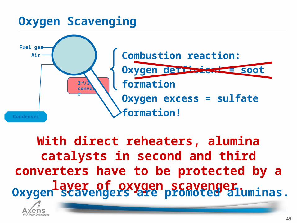
Oxygen Scavenging
With direct reheaters, alumina catalysts in second and third converters have to be
protected by a layer of oxygen scavenger.
Oxygen scavengers are promoted aluminas.
Condenser
ReheaterAir
Fuel gas
2nd/3rd
converter
Combustion reaction:
Oxygen defficient = soot formation
Oxygen excess = sulfate formation!
46
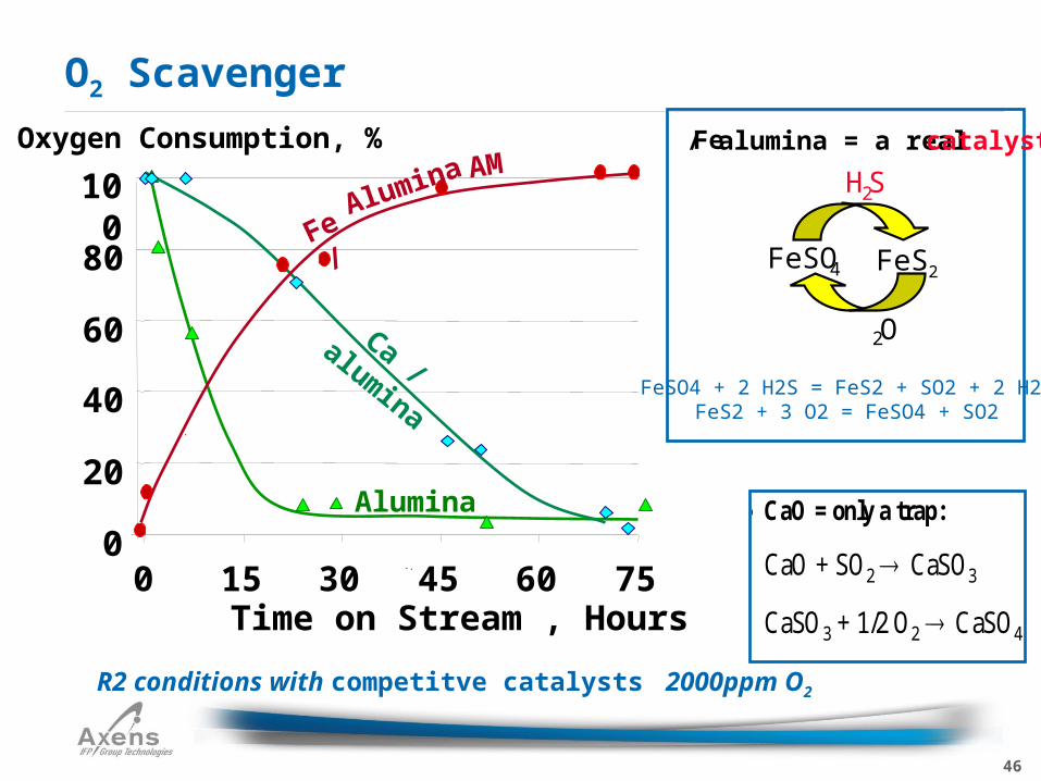
O2 Scavenger
R2 conditions with competitve catalysts 2000ppm O2
l CaO = only a trap:
CaO + SO2 CaSO3
CaSO3 + 1/2 O2 CaSO4
l Fe / alumina = a real catalyst:
H2S
FeSO4 ‘FeS2’
O2
Oxygen Consumption, %
.
0
20
40
60
80
100
0 15 30 45 60 75Time on Stream , Hours
Alumina
Ca / alumina
Fe /Alumina AM
FeSO4 + 2 H2S = FeS2 + SO2 + 2 H20FeS2 + 3 O2 = FeSO4 + SO2
Fe / alumina = a real catalyst
H2S
FeSO4 FeS2
O2
47
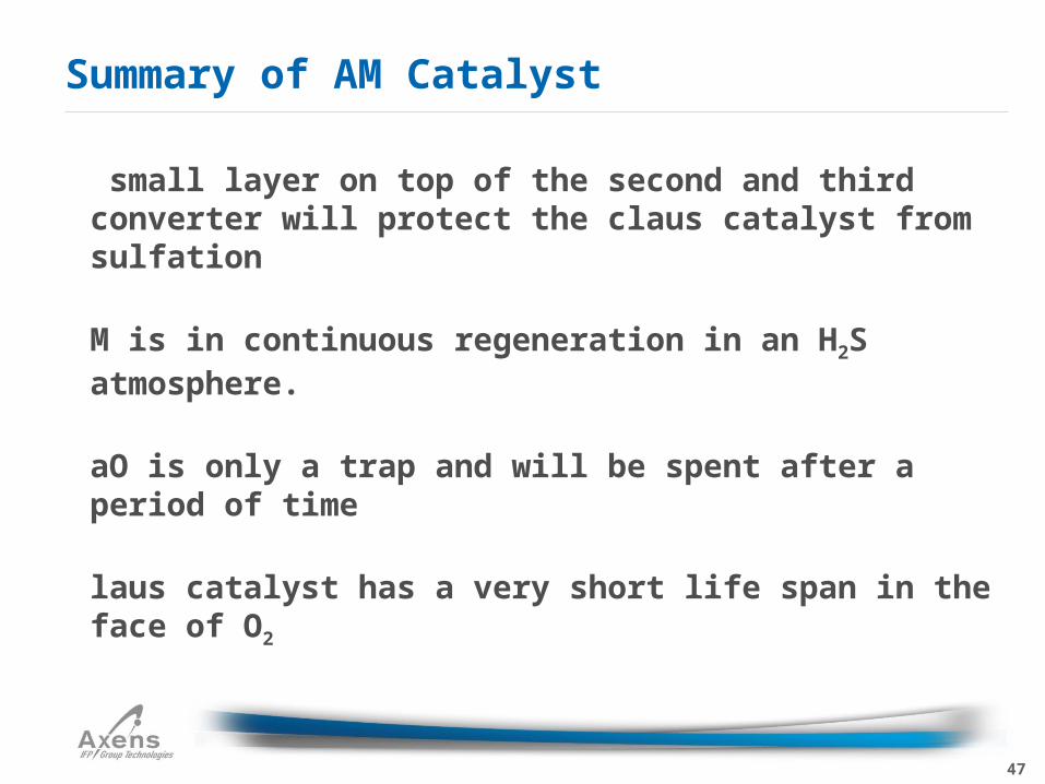
A small layer on top of the second and third converter will protect the claus catalyst from sulfation
AM is in continuous regeneration in an H2S atmosphere.
CaO is only a trap and will be spent after a period of time
Claus catalyst has a very short life span in the face of O2
Summary of AM Catalyst
48
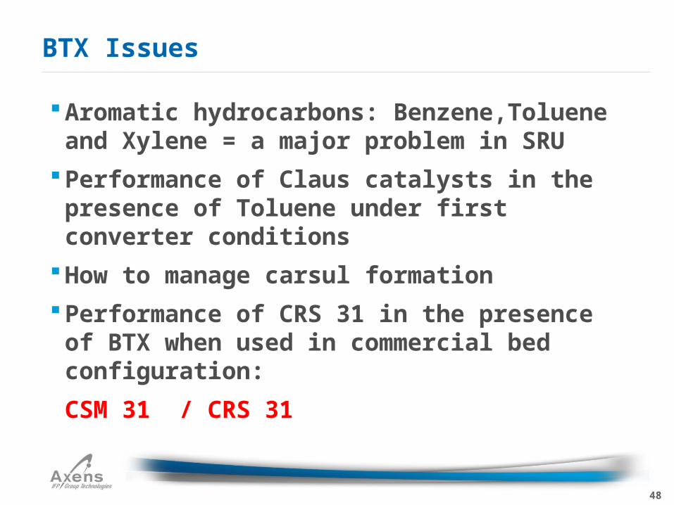
BTX Issues
Aromatic hydrocarbons: Benzene,Toluene and Xylene = a major problem in SRU
Performance of Claus catalysts in the presence of Toluene under first converter conditions
How to manage carsul formation
Performance of CRS 31 in the presence of BTX when used in commercial bed configuration:
CSM 31 / CRS 31
49
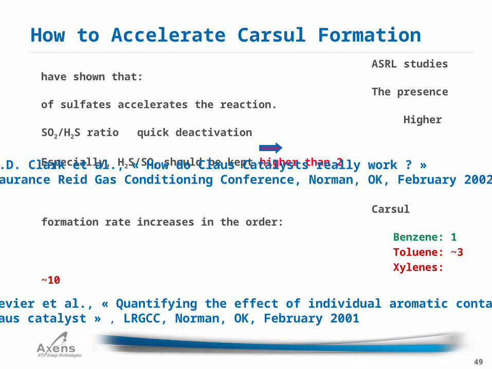
ASRL studies have shown that:
The presence of sulfates accelerates the reaction.
Higher SO2/H2S ratio quick deactivation
Especially, H2S/SO2 should be kept higher than 2
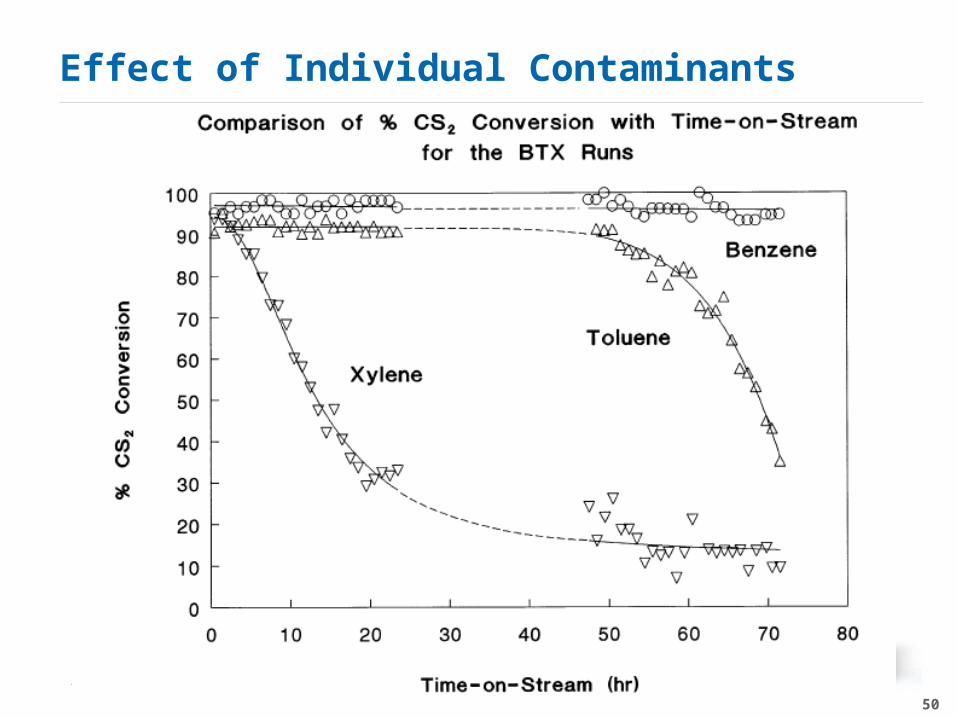
Carsul formation rate increases in the order:
Benzene: 1
Toluene: ~3
Xylenes: ~10
How to Accelerate Carsul Formation
P.D. Clark et al., « How do Claus Catalysts really work ? »Laurance Reid Gas Conditioning Conference, Norman, OK, February 2002
P. Crevier et al., « Quantifying the effect of individual aromatic contaminants on Claus catalyst » , LRGCC, Norman, OK, February 2001
50
Effect of Individual Contaminants
Axens Confidential
51
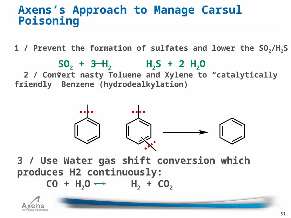
Axens’s Approach to Manage Carsul Poisoning
1 / Prevent the formation of sulfates and lower the SO2/H2S
2 / Convert nasty Toluene and Xylene to “catalytically friendly” Benzene (hydrodealkylation)
3 / Use Water gas shift conversion which produces H2 continuously:
CO + H2O H2 + CO2
SO2 + 3 H2 H2S + 2 H2O
52
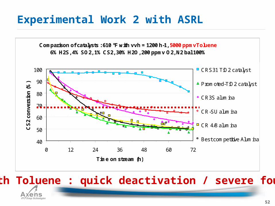
Experimental Work 2 with ASRL
With Toluene : quick deactivation / severe fouling
Comparison of catalysts : 610 °F with vvh = 1200 h-1, 5000 ppmvToluene6% H2S, 4% SO2, 1% CS2, 30% H2O, 200 ppmv O2, N2 bal 100%
40
50
60
70
80
90
100
0 12 24 36 48 60 72
Time on stream (h)
CS
2 co
nve
rsio
n (
%)
CRS31 TiO2 catalyst
Promoted-TiO2 catalyst
CR3S alumina
CR-SU alumina
CR 4/8 alumina
Best competitive Alumina
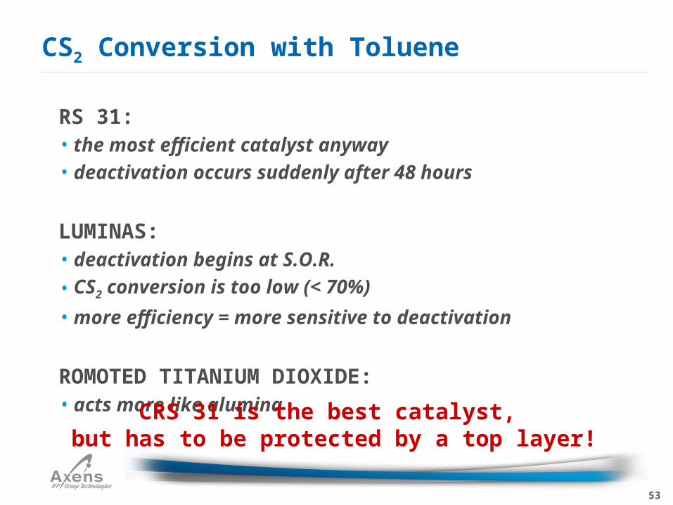
53
CRS 31:• the most efficient catalyst anyway• deactivation occurs suddenly after 48 hours
ALUMINAS:• deactivation begins at S.O.R.
• CS2 conversion is too low (< 70%)
• more efficiency = more sensitive to deactivation
PROMOTED TITANIUM DIOXIDE:• acts more like alumina
CS2 Conversion with Toluene
CRS 31 is the best catalyst, but has to be protected by a top layer!
54
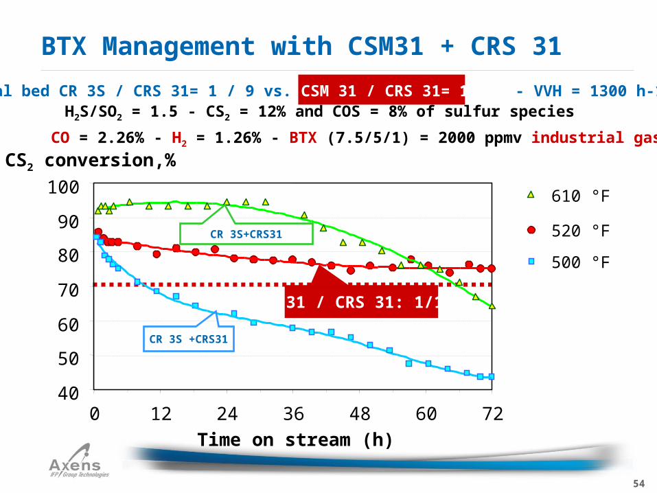
BTX Management with CSM31 + CRS 31
CSM 31 / CRS 31: 1/1
Dual bed CR 3S / CRS 31= 1 / 9 vs. CSM 31 / CRS 31= 1 / 1 - VVH = 1300 h-1H2S/SO2 = 1.5 - CS2 = 12% and COS = 8% of sulfur species
CO = 2.26% - H2 = 1.26% - BTX (7.5/5/1) = 2000 ppmv industrial gases
40
50
60
70
80
90
100
0 12 24 36 48 60 72
Time on stream (h)
CS2 conversion,%
500 °F
520 °F
610 °F
CR 3S +CRS31
CR 3S+CRS31
55
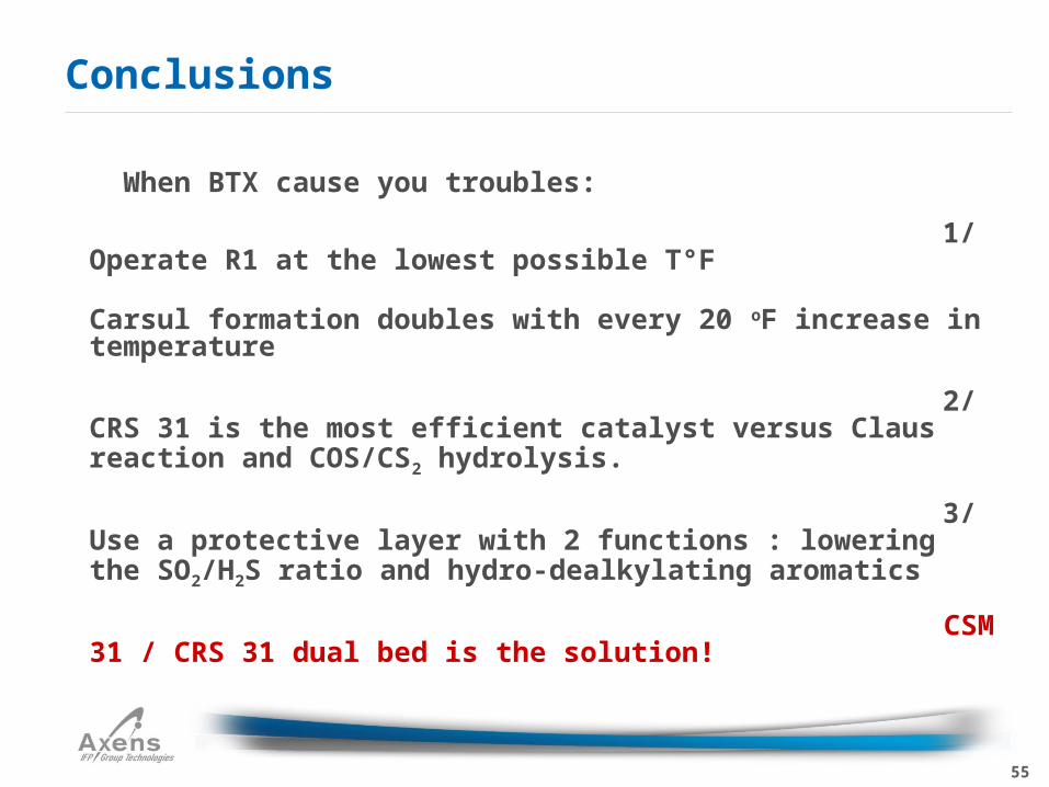
When BTX cause you troubles:
1/ Operate R1 at the lowest possible T°F
Carsul formation doubles with every 20 oF increase in temperature
2/ CRS 31 is the most efficient catalyst versus Claus reaction and COS/CS2 hydrolysis.
3/ Use a protective layer with 2 functions : lowering the SO2/H2S ratio and hydro-dealkylating aromatics
CSM 31 / CRS 31 dual bed is the solution!
Conclusions
56
Active Bed support for Claus unit• Replace inert supports with DR to improve activity of the Claus Unit
• Material is available in ½” and 3/8” spheres• Excellent crush strength• Lower cost of fill than standard inerts
DR
5757
Start-up/Shutdown
58
Once an SRU is started up it can often run for years continuously without the need to shut down
Catalyst replacement and boiler code requirements usually dictate the need to take the SRU offline
Start-up and shutdown are the times when the SRU is most at risk – most “incidents” occur here
Introduction
59
There are three Start-up cases to contend with•Cold Start-up with fresh catalyst•Cold Start-up with in-situ (used) catalyst•Hot Start-up
Start-up
60
General start-up sequence…
Start-up
61
Most critical points to monitor:•Fuel admission to the train•Check LEL with portable analyzer•Check Oxygen with portable analyzer
Start-up
62
Start-up
Rx.Furn.
Acid Gas
WHB Cond
Air
Conv
RH
Cond
Conv
RH
Cond
ConvRH
Air
FGCond
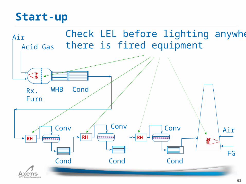
Check LEL before lighting anywherethere is fired equipment
63
Start-up
Rx.Furn.
Acid Gas
WHB Cond
Air
Conv
RH
Cond
Conv
RH
Cond
ConvRH
Air
FGCond
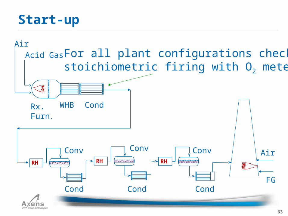
For all plant configurations check stoichiometric firing with O2 meter
64
For this unique, special condition, stoichiometric firing is not critical
XS air can be used - but only for this case
The focus needs to be on RF refractory curing
Follow manufacturers recommendation for temperature ramping of fresh or in situ refractory
Cold Start-up & Fresh Catalyst
65
Even in this case it is advisable to use quenching steam (more about this in a moment)
When the beds are up to temperature introduce acid gas
Cold Start-up & Fresh Catalyst
66
Now there are two points to be aware of:•RF refractory curing – as always
•Need to keep converters in an O2 free environment as they are heated up
Now the flexibility to use excess air is not possible, quenching steam is mandatory
Reaction Furnace must be started up on stoichiometric firing or a converter fire is possible if not probable
Cold Start-up with Used Catalyst
67
Many refineries have a significant amount of H2 in the fuel gas
It is noteworthy that although the heat of combustion of H2 is less than a third that of C1, the adiabatic flame temperature of H2 is higher than that of C1
Cold Start-up with Used Catalyst
68
Fuel gas firing needs to be tempered with quench steam to moderate the flame temperature
Use at 4 – 5 kg steam / kg of fuel
Hydrogen content of the fuel gas does not significantly affect this rule of thumb
Cold Start-up with Used Catalyst
69
Sequence summary:•Light off Thermal Oxidizer•Light off Reaction Furnace – Maintain Stoichiometry
•R.F. refractory curing•Light off / commission reheaters• Introduce acid gas
Cold Start-up with Used Catalyst
70
One of the more hazardous SRU scenarios
Ex. the plant tripped and is to be brought back online A.S.A.P.
Refractory curing is not a concern
The hot catalyst beds and R.F are the issues
Critical not to admit free oxygen to the beds
Danger of introducing fuel to hot RF
Hot Start-up
71
Start Thermal Oxidizer
Purge R.F. with 5 volume units of N2
Light off R.F. with fuel – switch immediately to acid gas
Light off / commission reheaters
The key is to limit successive attempts at lighting the R.F.
After two failed light off attempts re-purge the R.F. with 5 volume units of Nitrogen
Hot Start-up
72
Heat soak
Fuel gas firing
Air ramping
Air cooling
When things go wrong
Shutdown
73
In stock inventories for immediate delivery• CR-3S, CR, DR, AMS and CRS-31
We can provide Technical Assistance• Projections• Troubleshooting• On site loading and start-up support
We will guarantee the performance of our products
What We Can Provide
74
Ensure the tail gas analyzer is on line
The unit must be dried out under fuel gas firing
Pyrophoric material inevitably builds up in the SRU during operation
Burning this off in a controlled manner is the key to a safe shutdown
Close watch on catalyst bed temperature profiles
Record keeping & patience
Key Points for a Successful Shutdown
75
Many things can go wrong during a shutdown
There is always pressure from Maintenance to speed things up
Best Practice is to have the Lead Operator sign off a Shutdown Log with all the required steps pre-printed
Industry Best Practice
76
Increase all converter inlet temperatures to 260 °C or as high as possible if reheaters are steam heated
Reduce acid gas to increase temperature
For small trains < 100 TPD minimum 12 hrs
For larger trains minimum 24 hrs
Reason
•Remove SL from within catalyst pores
•Reduce the chance of fires in the beds
Heat Soak
77
Reduce acid gas to 25% – 30% of design rate
Introduce fuel gas
Drop out acid gas and set stoichiometric firing
Here it is VERY CRITICAL to maintain stoichiometry firing
Add quench steam: 4 – 5 kg per kg fuel
Check excess O2 at first condenser
Fuel Gas Firing
78
Use the maximum fuel rate subject to quench steam availability to maintain ~ 1300 °C in R.F.
Note that even for refineries mass flow rate on fuel gas firing is still less than process flow at the same burner heat release rate
More fuel flow means a faster shutdown
Continue until all sulfur rundowns have stopped flowing – this can take several days large plants > 400 MTD
Fuel Gas Firing
79
Shutdown the catalytic stage reheaters
Keep firing stoichiometrically until ALL beds are below 200 °C
Be patient
This is the step you don’t want to rush
Really have patience – tell maintenance to relax!
Fuel Gas Firing
80
This is one to take your time on
Verify that the tail gas analyser is in service
Even after the heat soak and fuel gas firing there are still combustible materials in the SRU•Residual sulfur deep in the catalyst pores•Pyrophoric iron
This has to be “burned off” in a controlled way
The main air valve is to big for fine control
Air Ramping
81
Use the trim air valve
Open the trim air valve in steps of 5% of valve opening
At each step, allow a minimum of 20 minutes before making another change to the trim valve position
Keep a close watch on tail gas analyzer for any sudden increases in SO2
Air Ramping
82
Ramp up air while reducing steam in small steps while maintaining ~ 1300 °C in the R.F.
When steam is blocked in excess oxygen should be about 14%
Fire this way with no steam for 8 hours
Increase air until flame becomes unstable
Shut off and isolate fuel gas when the R.F. temperature is about 450 °C
Air Ramping
83
Run air blowers at 50% of normal process flow with all valves open
(minimum discharge pressure – minimum temperature)
Continue cooling until the train reaches air blower temperature
Now maintenance can do their work safely
Air Ramping
84
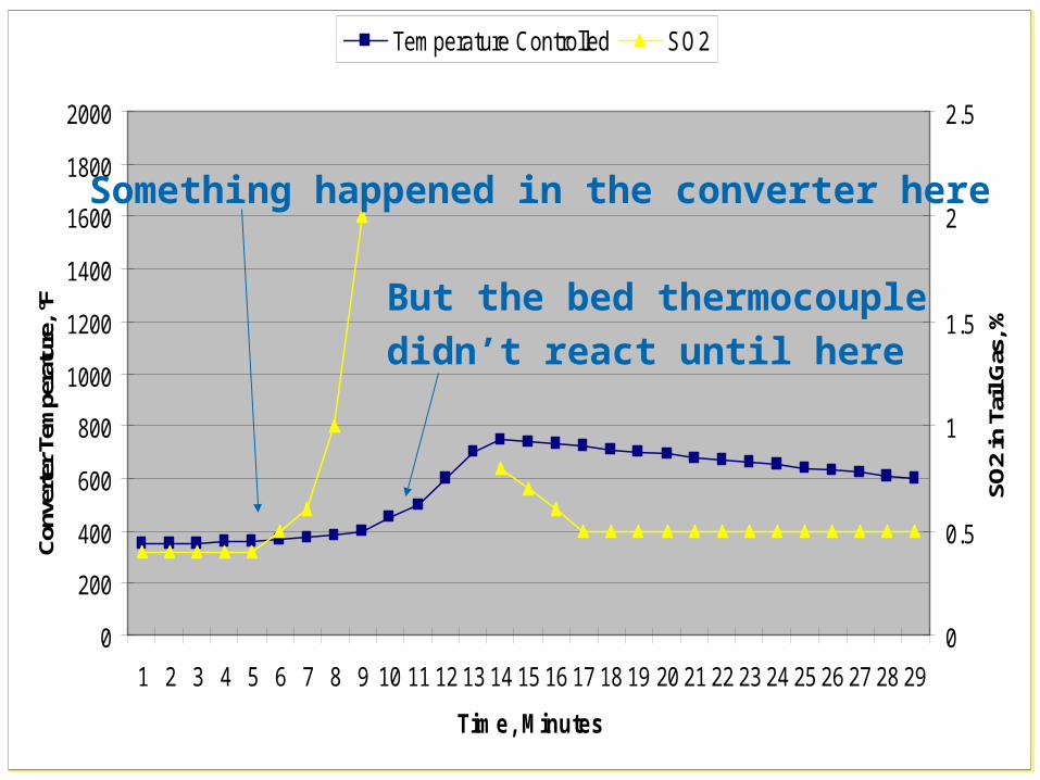
The SO2 reading from the analyzer gives advance warning of a temperature excursion in a converter
Abnormal Situations
85Axens Confidential
0
200
400
600
800
1000
1200
1400
1600
1800
2000
1 2 3 4 5 6 7 8 9 10 11 12 13 14 15 16 17 18 19 20 21 22 23 24 25 26 27 28 29
Time, Minutes
Conv
erte
r Tem
pera
ture
, °F
0
0.5
1
1.5
2
2.5
SO2
in T
ail G
as, %
Temperature Controlled SO2
0
200
400
600
800
1000
1200
1400
1600
1800
2000
1 2 3 4 5 6 7 8 9 10 11 12 13 14 15 16 17 18 19 20 21 22 23 24 25 26 27 28 29
Time, Minutes
Conv
erte
r Tem
pera
ture
, °F
0
0.5
1
1.5
2
2.5
SO2
in T
ail G
as, %
Temperature Controlled SO2
Something happened in the converter here
But the bed thermocouple
didn’t react until here
86
Rapid increase in tail gas SO2 during stoichiometric fuel firing•Go to sub-stoichiometric firing (~ 90 - 95%)
•Wait for SO2 to start coming down
•Return to stoichiometric firingR
apid increase in tail gas SO2 during air ramping
•Return to stoichiometric firing
•Wait for SO2 to start coming down
•Return to air ramping
Abnormal Situations
87
Reduce to R.F. air rate so as to achieve an H2S/SO2 ratio of between 6-10 in the tail gas
Raise the temperature of the second and third converters up to 235 °C if possible
At lower H2S/SO2 ratio and temperature it will take longer to react the sulphate
Operate in rejuvenation mode for 12 to 36 hours depending on ratio, temperature and plant size
Rejuvenation Procedure
88
It is sometimes used in gas plants that have aromatic contaminant issues
Refineries should never need to do regenerations
We do not recommend this procedure because of the risks involved
It is mentioned here only for completeness of a discussion of SRU operations
Regeneration
89
It is always desirable to keep an SRU running when that option is available
The unit is always stressed when either started up or shutdown
Typically this is when damage to refractory and other components occurs
Safe start-up and shut downs are achieved with careful planning, team work and patience
Concluding Remarks


![Epitaxial Strain-Induced Growth of CuO at Cu O/ZnO …folk.uio.no/olem/papers/gunnaes2016.pdf · Epitaxial Strain-Induced Growth of CuO at Cu ... CuO interfacial plane we have (111)[11̅0]](https://img.pdfslide.net/doc/110x75/5a9a85b57f8b9aba4a8d8aa8/epitaxial-strain-induced-growth-of-cuo-at-cu-ozno-folkuionoolempapers-strain-induced.jpg)


![TIII team: Presentation final event [CUO]](https://img.pdfslide.net/doc/110x75/5564607bd8b42a951e8b4e96/tiii-team-presentation-final-event-cuo.jpg)