Embed Size (px)
Citation preview
martens
Preliminary Salinity and Geotechnical Assessment: 37 Worcester Road, Rouse Hill, NSW.
P1504946JR01V02 – August 2017
Page 38
11 Attachment C – Borehole Logs
Qua
lityS
heet
No.
4
(C) Copyright Martens & Associates Pty. Ltd . 2015
Engineering Log -MARTENS & ASSOCIATES PTY LTDSuite 201, 20 george St, Hornsby, NSW 2077 Australia
Phone: (02) 9476 9999 Fax: (02) 9476 [email protected] WEB: http://www.martens.com.au
P1504946
1.0
2.0
3.0
4.0
1.0
2.0
3.0
4.0
4.54.5
martens
REFSheet of
SUPP
OR
T
WAT
ER RESULTS ANDADDITIONAL OBSERVATIONS
EXCAVATION DATA
MET
HO
D
MATERIAL DATA SAMPLING & TESTING
EXCAVATION LOG TO BE READ IN CONJUNCTION WITH ACCOMPANYING REPORT NOTES AND ABBREVIATIONS
MO
ISTU
RE
DEP
TH(M
)
TYPE
DEP
TH(M
)
CLIENT
PROJECT NO.
PROJECTSITE
DR
ILLI
NG
RES
ISTA
NC
E
L M H R
EQUIPMENT
EXCAVATION DIMENSIONS
EASTING
NORTHING
RL SURFACE
ASPECT
COMMENCED
LOGGED
GEOLOGY
COMPLETED
CHECKED
VEGETATION
EQUIPMENT / METHODN Natural exposureX Existing excavationBH Backhoe bucketHA Hand augerS SpadeCC Concrete CorerV V-bitTC Tungsten Carbide BitPT Push tube
MOISTURED DryM MoistW WetWp Plastic limitWl Liquid limit
WATERN None observedX Not measured
Water level
Water outflow
Water inflow
SUPPORTSH ShoringSC ShotcreteRB Rock BoltsNil No support
CLASSIFICATIONSYMBOLS ANDSOIL DESCRIPTION
USCS
Agricultural
CONSISTENCYVS Very SoftS SoftF FirmSt StiffVSt Very StiffH HardF Friable
DENSITYVL Very LooseL LooseMD Medium DenseD DenseVD Very Dense
DRILLINGRESISTANCEL LowM ModerateH HighR Refusal
SLOPE
SAMPLING & TESTINGA Auger sampleB Bulk sampleU Undisturbed sampleD Disturbed sampleUx Tube sample (x mm)pp Pocket penetrometerSPT Standard penetration testCBR California Bearing Ratio
VS Vane shearDCP Dynamic cone
penetrometerFD Field densityM Moisture contentWS Water sample
GR
APH
ICLO
G
CLA
SSIF
ICAT
ION
CO
NSI
STEN
CY
DEN
SITY
IND
EXMATERIAL DESCRIPTIONSOIL NAME, plasticity or particle characteristics,
colour, secondary and minor components,moisture condition, consistency/relative density,ROCK NAME, grain size, texture/fabric, colour,
strength, weathering.
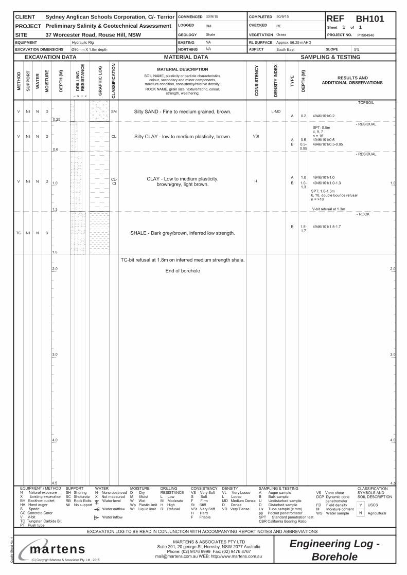
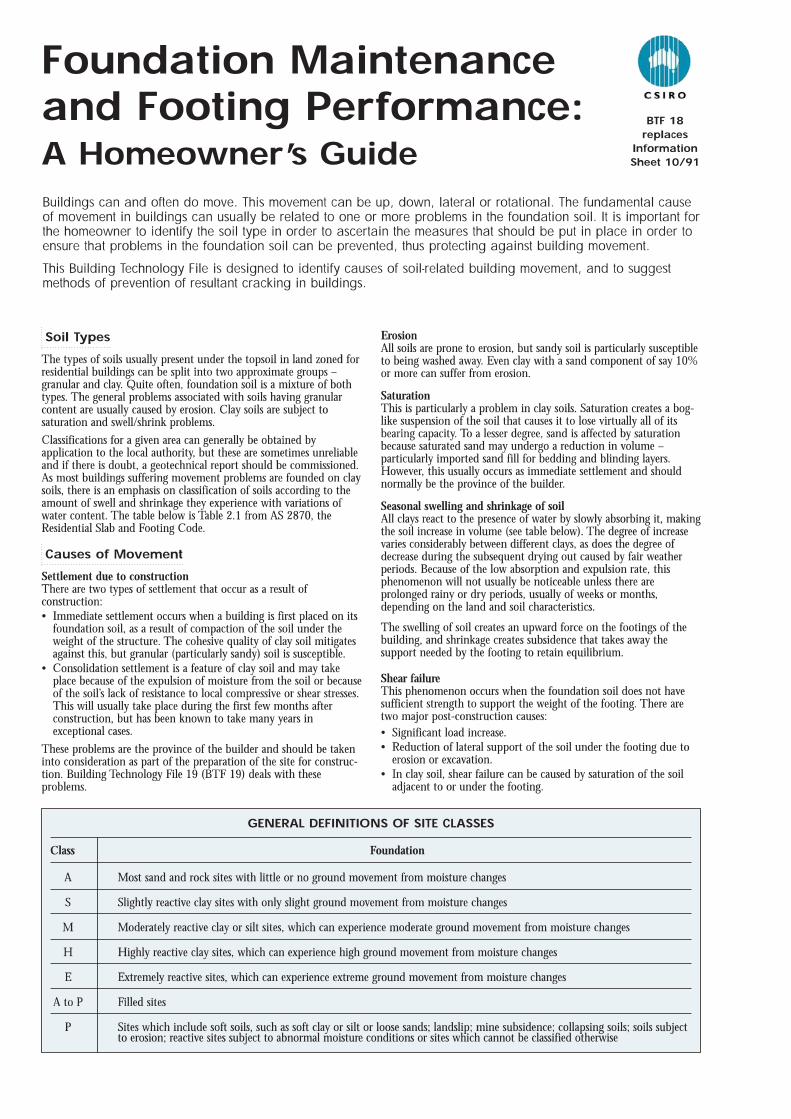
BH101
Silty SAND - Fine to medium grained, brown.V Nil N D SM
0.6- RESIDUAL
Silty CLAY - low to medium plasticity, brown.V Nil N D CL
0.25- RESIDUAL
N
Y
Borehole
1 1
Hydraulic Rig
Ø90mm X 1.8m depth
Approx. 56.25 mAHD
South East
30/9/15
BM
Shale
30/9/15
RE
Grass
5%
Sydney Anglican Schools Corporation, C/- TerriorPreliminary Salinity & Geotechnical Assessment37 Worcester Road, Rouse Hill, NSW
TC-bit refusal at 1.8m on inferred medium strength shale.
End of borehole
CLAY - Low to medium plasticity,brown/grey, light brown.V Nil N D CL-
CI
- TOPSOIL
1.8
1.3- ROCK
SHALE - Dark grey/brown, inferred low strength.TC Nil N D
B 1.5-1.7
4946/101/1.5-1.7
SPT: 1.0-1.3m6, 18, double bounce refusaln = >18
A 0.2 4946/101/0.2
B 1.0-1.3
4946/101/1.0-1.3
B 0.5-0.95
4946/101/0.5-0.95A 0.5 4946/101/0.5
SPT: 0.5m4, 9, 7n = 16
A 1.0 4946/101/1.0
NA
L-MD
VSt
H
V-bit refusal at 1.3m
NA

Qua
lityS
heet
No.
4
(C) Copyright Martens & Associates Pty. Ltd . 2015
Engineering Log -MARTENS & ASSOCIATES PTY LTDSuite 201, 20 george St, Hornsby, NSW 2077 Australia
Phone: (02) 9476 9999 Fax: (02) 9476 [email protected] WEB: http://www.martens.com.au
P1504946
1.0
2.0
3.0
4.0
1.0
2.0
3.0
4.0
4.54.5
martens
REFSheet of
SUPP
OR
T
WAT
ER RESULTS ANDADDITIONAL OBSERVATIONS
EXCAVATION DATA
MET
HO
D
MATERIAL DATA SAMPLING & TESTING
EXCAVATION LOG TO BE READ IN CONJUNCTION WITH ACCOMPANYING REPORT NOTES AND ABBREVIATIONS
MO
ISTU
RE
DEP
TH(M
)
TYPE
DEP
TH(M
)
CLIENT
PROJECT NO.
PROJECTSITE
DR
ILLI
NG
RES
ISTA
NC
E
L M H R
EQUIPMENT
EXCAVATION DIMENSIONS
EASTING
NORTHING
RL SURFACE
ASPECT
COMMENCED
LOGGED
GEOLOGY
COMPLETED
CHECKED
VEGETATION
EQUIPMENT / METHODN Natural exposureX Existing excavationBH Backhoe bucketHA Hand augerS SpadeCC Concrete CorerV V-bitTC Tungsten Carbide BitPT Push tube
MOISTURED DryM MoistW WetWp Plastic limitWl Liquid limit
WATERN None observedX Not measured
Water level
Water outflow
Water inflow
SUPPORTSH ShoringSC ShotcreteRB Rock BoltsNil No support
CLASSIFICATIONSYMBOLS ANDSOIL DESCRIPTION
USCS
Agricultural
CONSISTENCYVS Very SoftS SoftF FirmSt StiffVSt Very StiffH HardF Friable
DENSITYVL Very LooseL LooseMD Medium DenseD DenseVD Very Dense
DRILLINGRESISTANCEL LowM ModerateH HighR Refusal
SLOPE
SAMPLING & TESTINGA Auger sampleB Bulk sampleU Undisturbed sampleD Disturbed sampleUx Tube sample (x mm)pp Pocket penetrometerSPT Standard penetration testCBR California Bearing Ratio
VS Vane shearDCP Dynamic cone
penetrometerFD Field densityM Moisture contentWS Water sample
GR
APH
ICLO
G
CLA
SSIF
ICAT
ION
CO
NSI
STEN
CY
DEN
SITY
IND
EXMATERIAL DESCRIPTIONSOIL NAME, plasticity or particle characteristics,
colour, secondary and minor components,moisture condition, consistency/relative density,ROCK NAME, grain size, texture/fabric, colour,
strength, weathering.
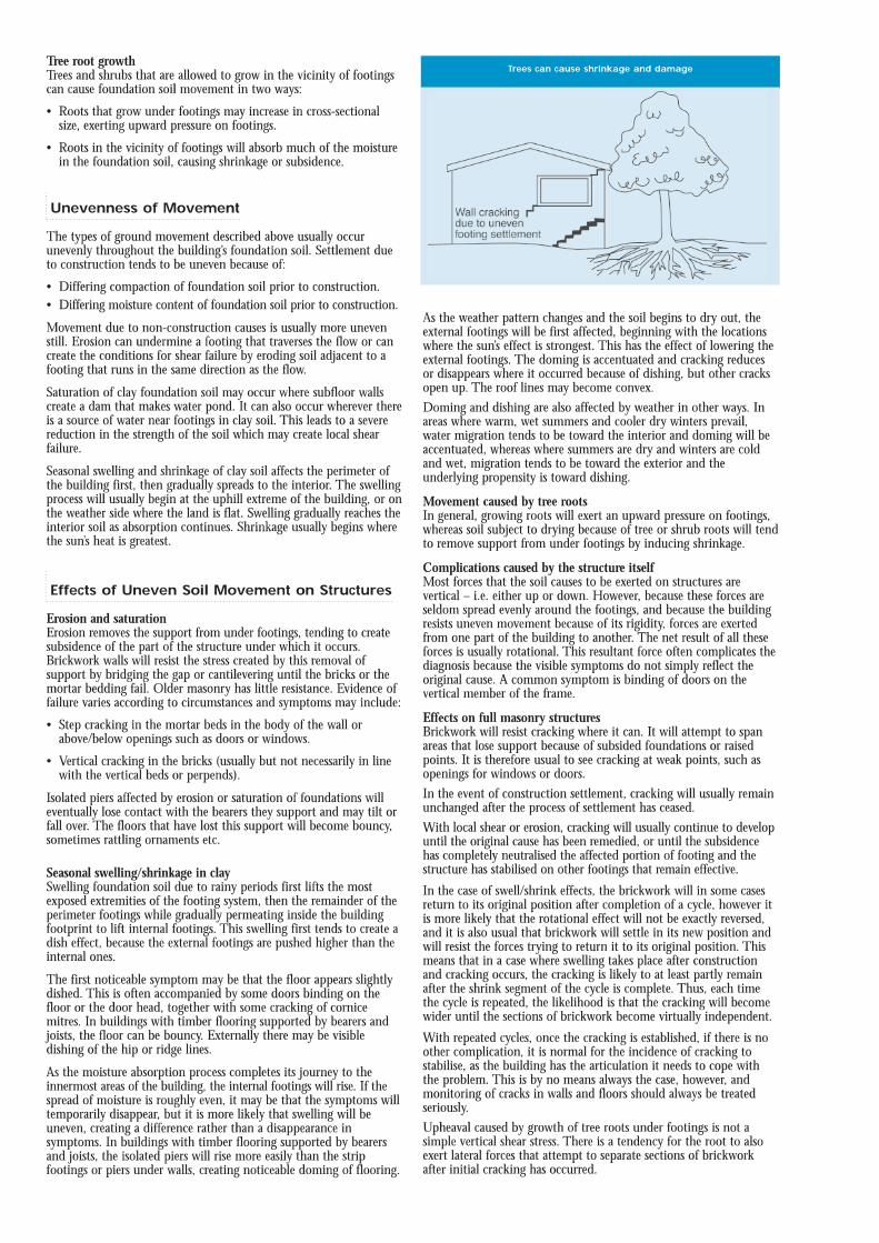
BH102
Silty SAND - Fine to medium grained, brown.V Nil N D SM
0.7- RESIDUAL
Silty CLAY - low to medium plasticity, brown.V Nil N D CL
0.2- RESIDUAL
N
Y
Borehole
1 1
Hydraulic Rig
Ø90mm X 2.7m depth
NA
NA
Approx. 59.85 mAHD
South East
30/9/15
BM
Shale
30/9/15
RE
Grass
5%
Sydney Anglican Schools Corporation, C/- TerriorPreliminary Salinity & Geotechnical Assessment37 Worcester Road, Rouse Hill, NSW
TC-bit refusal at 2.7m on inferred medium strength shale.
End of borehole.
CLAY - Low plasticity, light brown/ brown/grey.V Nil N D CL
- TOPSOIL
2.7
1.3- ROCK
SHALE - Light brown/grey, inferred low strength.TC Nil N D
A 0.2 4946/102/0.2
A 0.5 4946/102/0.5
A 1.0 4946/102/1.0
0.4- RESIDUAL
CLAY - Low to medium plasticity, brown/red brown.V Nil N D CL-CI
V-bit refusal at 1.3m
L-MD
St-VSt
VSt
St-VSt
A 1.5 4946/102/1.5
Grading to
Qua
lityS
heet
No.
4
(C) Copyright Martens & Associates Pty. Ltd . 2015
Engineering Log -MARTENS & ASSOCIATES PTY LTDSuite 201, 20 george St, Hornsby, NSW 2077 Australia
Phone: (02) 9476 9999 Fax: (02) 9476 [email protected] WEB: http://www.martens.com.au
P1504946
1.0
2.0
3.0
4.0
1.0
2.0
3.0
4.0
4.54.5
martens
REFSheet of
SUPP
OR
T
WAT
ER RESULTS ANDADDITIONAL OBSERVATIONS
EXCAVATION DATA
MET
HO
D
MATERIAL DATA SAMPLING & TESTING
EXCAVATION LOG TO BE READ IN CONJUNCTION WITH ACCOMPANYING REPORT NOTES AND ABBREVIATIONS
MO
ISTU
RE
DEP
TH(M
)
TYPE
DEP
TH(M
)
CLIENT
PROJECT NO.
PROJECTSITE
DR
ILLI
NG
RES
ISTA
NC
E
L M H R
EQUIPMENT
EXCAVATION DIMENSIONS
EASTING
NORTHING
RL SURFACE
ASPECT
COMMENCED
LOGGED
GEOLOGY
COMPLETED
CHECKED
VEGETATION
EQUIPMENT / METHODN Natural exposureX Existing excavationBH Backhoe bucketHA Hand augerS SpadeCC Concrete CorerV V-bitTC Tungsten Carbide BitPT Push tube
MOISTURED DryM MoistW WetWp Plastic limitWl Liquid limit
WATERN None observedX Not measured
Water level
Water outflow
Water inflow
SUPPORTSH ShoringSC ShotcreteRB Rock BoltsNil No support
CLASSIFICATIONSYMBOLS ANDSOIL DESCRIPTION
USCS
Agricultural
CONSISTENCYVS Very SoftS SoftF FirmSt StiffVSt Very StiffH HardF Friable
DENSITYVL Very LooseL LooseMD Medium DenseD DenseVD Very Dense
DRILLINGRESISTANCEL LowM ModerateH HighR Refusal
SLOPE
SAMPLING & TESTINGA Auger sampleB Bulk sampleU Undisturbed sampleD Disturbed sampleUx Tube sample (x mm)pp Pocket penetrometerSPT Standard penetration testCBR California Bearing Ratio
VS Vane shearDCP Dynamic cone
penetrometerFD Field densityM Moisture contentWS Water sample
GR
APH
ICLO
G
CLA
SSIF
ICAT
ION
CO
NSI
STEN
CY
DEN
SITY
IND
EXMATERIAL DESCRIPTIONSOIL NAME, plasticity or particle characteristics,
colour, secondary and minor components,moisture condition, consistency/relative density,ROCK NAME, grain size, texture/fabric, colour,
strength, weathering.
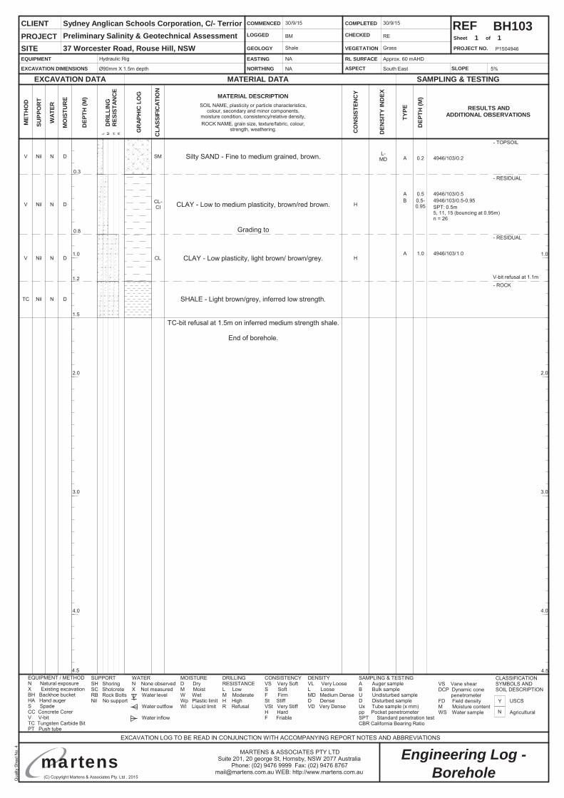
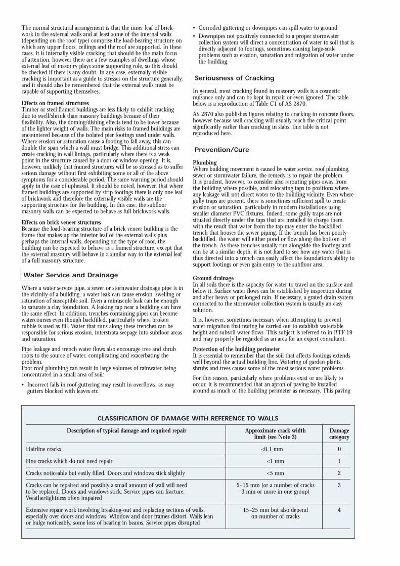
Silty SAND - Fine to medium grained, brown.V Nil N D SM
0.8- RESIDUAL
BH103
0.3- RESIDUAL
N
Y
Borehole
1 1
Hydraulic Rig
Ø90mm X 1.5m depth
NA
NA
Approx. 60 mAHD
South East
30/9/15
BM
Shale
30/9/15
RE
Grass
5%
Sydney Anglican Schools Corporation, C/- TerriorPreliminary Salinity & Geotechnical Assessment37 Worcester Road, Rouse Hill, NSW
TC-bit refusal at 1.5m on inferred medium strength shale.
End of borehole.
CLAY - Low plasticity, light brown/ brown/grey.V Nil N D CL
- TOPSOIL
1.5
1.2- ROCK
SHALE - Light brown/grey, inferred low strength.TC Nil N D
A 0.2 4946/103/0.2
A 0.5 4946/103/0.5
A 1.0 4946/103/1.0
CLAY - Low to medium plasticity, brown/red brown.V Nil N D CL-CI
V-bit refusal at 1.1m
L-MD
H
H
Grading to
SPT: 0.5m5, 11, 15 (bouncing at 0.95m)n = 26
B 0.5-0.95
4946/103/0.5-0.95
Qua
lityS
heet
No.
4
(C) Copyright Martens & Associates Pty. Ltd . 2015
Engineering Log -MARTENS & ASSOCIATES PTY LTDSuite 201, 20 george St, Hornsby, NSW 2077 Australia
Phone: (02) 9476 9999 Fax: (02) 9476 [email protected] WEB: http://www.martens.com.au
P1504946
1.0
2.0
3.0
4.0
1.0
2.0
3.0
4.0
4.54.5
martens
REFSheet of
SUPP
OR
T
WAT
ER RESULTS ANDADDITIONAL OBSERVATIONS
EXCAVATION DATA
MET
HO
D
MATERIAL DATA SAMPLING & TESTING
EXCAVATION LOG TO BE READ IN CONJUNCTION WITH ACCOMPANYING REPORT NOTES AND ABBREVIATIONS
MO
ISTU
RE
DEP
TH(M
)
TYPE
DEP
TH(M
)
CLIENT
PROJECT NO.
PROJECTSITE
DR
ILLI
NG
RES
ISTA
NC
E
L M H R
EQUIPMENT
EXCAVATION DIMENSIONS
EASTING
NORTHING
RL SURFACE
ASPECT
COMMENCED
LOGGED
GEOLOGY
COMPLETED
CHECKED
VEGETATION
EQUIPMENT / METHODN Natural exposureX Existing excavationBH Backhoe bucketHA Hand augerS SpadeCC Concrete CorerV V-bitTC Tungsten Carbide BitPT Push tube
MOISTURED DryM MoistW WetWp Plastic limitWl Liquid limit
WATERN None observedX Not measured
Water level
Water outflow
Water inflow
SUPPORTSH ShoringSC ShotcreteRB Rock BoltsNil No support
CLASSIFICATIONSYMBOLS ANDSOIL DESCRIPTION
USCS
Agricultural
CONSISTENCYVS Very SoftS SoftF FirmSt StiffVSt Very StiffH HardF Friable
DENSITYVL Very LooseL LooseMD Medium DenseD DenseVD Very Dense
DRILLINGRESISTANCEL LowM ModerateH HighR Refusal
SLOPE
SAMPLING & TESTINGA Auger sampleB Bulk sampleU Undisturbed sampleD Disturbed sampleUx Tube sample (x mm)pp Pocket penetrometerSPT Standard penetration testCBR California Bearing Ratio
VS Vane shearDCP Dynamic cone
penetrometerFD Field densityM Moisture contentWS Water sample
GR
APH
ICLO
G
CLA
SSIF
ICAT
ION
CO
NSI
STEN
CY
DEN
SITY
IND
EXMATERIAL DESCRIPTIONSOIL NAME, plasticity or particle characteristics,
colour, secondary and minor components,moisture condition, consistency/relative density,ROCK NAME, grain size, texture/fabric, colour,
strength, weathering.
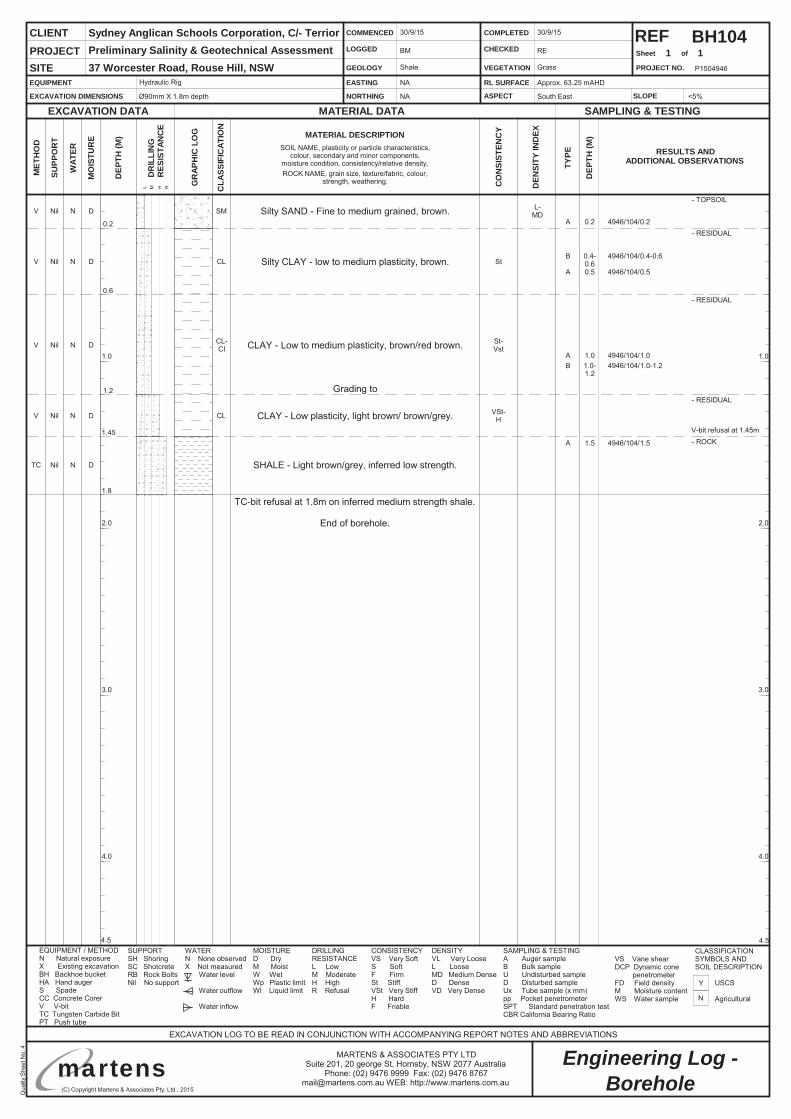
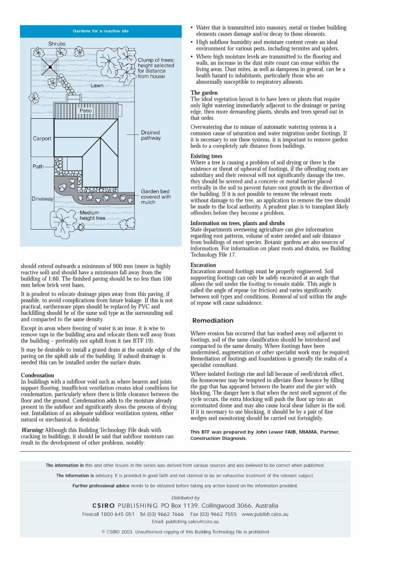
BH104
Silty SAND - Fine to medium grained, brown.V Nil N D SM
1.2- RESIDUAL
Silty CLAY - low to medium plasticity, brown.V Nil N D CL
0.2- RESIDUAL
N
Y
Borehole
1 1
Hydraulic Rig
Ø90mm X 1.8m depth
NA
NA
Approx. 63.25 mAHD
South East
30/9/15
BM
Shale
30/9/15
RE
Grass
<5%
Sydney Anglican Schools Corporation, C/- Terrior
37 Worcester Road, Rouse Hill, NSW
TC-bit refusal at 1.8m on inferred medium strength shale.
End of borehole.
CLAY - Low plasticity, light brown/ brown/grey.V Nil N D CL
- TOPSOIL
1.8
1.45- ROCK
SHALE - Light brown/grey, inferred low strength.TC Nil N D
A 0.2 4946/104/0.2
A 0.5 4946/104/0.5
A 1.0 4946/104/1.0
0.6- RESIDUAL
CLAY - Low to medium plasticity, brown/red brown.V Nil N D CL-CI
V-bit refusal at 1.45m
L-MD
St
VSt-H
St-Vst
A 1.5 4946/104/1.5
Grading to
B 0.4-0.6
4946/104/0.4-0.6
B 1.0-1.2
4946/104/1.0-1.2
Preliminary Salinity & Geotechnical Assessment

Qua
lityS
heet
No.
4
(C) Copyright Martens & Associates Pty. Ltd . 2015
Engineering Log -MARTENS & ASSOCIATES PTY LTDSuite 201, 20 george St, Hornsby, NSW 2077 Australia
Phone: (02) 9476 9999 Fax: (02) 9476 [email protected] WEB: http://www.martens.com.au
P1504946
1.0
2.0
3.0
4.0
1.0
2.0
3.0
4.0
4.54.5
martens
REFSheet of
SUPP
OR
T
WAT
ER RESULTS ANDADDITIONAL OBSERVATIONS
EXCAVATION DATA
MET
HO
D
MATERIAL DATA SAMPLING & TESTING
EXCAVATION LOG TO BE READ IN CONJUNCTION WITH ACCOMPANYING REPORT NOTES AND ABBREVIATIONS
MO
ISTU
RE
DEP
TH(M
)
TYPE
DEP
TH(M
)
CLIENT
PROJECT NO.
PROJECTSITE
DR
ILLI
NG
RES
ISTA
NC
E
L M H R
EQUIPMENT
EXCAVATION DIMENSIONS
EASTING
NORTHING
RL SURFACE
ASPECT
COMMENCED
LOGGED
GEOLOGY
COMPLETED
CHECKED
VEGETATION
EQUIPMENT / METHODN Natural exposureX Existing excavationBH Backhoe bucketHA Hand augerS SpadeCC Concrete CorerV V-bitTC Tungsten Carbide BitPT Push tube
MOISTURED DryM MoistW WetWp Plastic limitWl Liquid limit
WATERN None observedX Not measured
Water level
Water outflow
Water inflow
SUPPORTSH ShoringSC ShotcreteRB Rock BoltsNil No support
CLASSIFICATIONSYMBOLS ANDSOIL DESCRIPTION
USCS
Agricultural
CONSISTENCYVS Very SoftS SoftF FirmSt StiffVSt Very StiffH HardF Friable
DENSITYVL Very LooseL LooseMD Medium DenseD DenseVD Very Dense
DRILLINGRESISTANCEL LowM ModerateH HighR Refusal
SLOPE
SAMPLING & TESTINGA Auger sampleB Bulk sampleU Undisturbed sampleD Disturbed sampleUx Tube sample (x mm)pp Pocket penetrometerSPT Standard penetration testCBR California Bearing Ratio
VS Vane shearDCP Dynamic cone
penetrometerFD Field densityM Moisture contentWS Water sample
GR
APH
ICLO
G
CLA
SSIF
ICAT
ION
CO
NSI
STEN
CY
DEN
SITY
IND
EXMATERIAL DESCRIPTIONSOIL NAME, plasticity or particle characteristics,
colour, secondary and minor components,moisture condition, consistency/relative density,ROCK NAME, grain size, texture/fabric, colour,
strength, weathering.
SPT: 0.5m-0.95m5, 8, 10n = 18
BH105
Silty SAND - Fine to medium grained, brown.V Nil N D SM
0.8- RESIDUAL
0.2- RESIDUAL
N
Y
Borehole
1 1
Ø90mm X 1.7m depth
NA
NA
Approx. 66.1 mAHD
South East
30/9/15
BM
Shale
30/9/15
RE
Grass
5%
Sydney Anglican Schools Corporation, C/- TerriorPreliminary Salinity and Geotechnical Assessment37 Worcester Road, Rouse Hill, NSW
TC-bit refusal at 1.7m on inferred medium strength shale.
End of borehole.
CLAY - Low plasticity, light brown/ brown/grey.V Nil N D CL
- TOPSOIL
1.7
1.4- ROCK
SHALE - Light brown/grey, inferred low strength.TC Nil N D
A 0.2 4946/105/0.2
A 0.5 4946/105/0.5CLAY - Low to medium plasticity, brown/red brown.V Nil N D CL-
CI
V-bit refusal at 1.4m
L-MD
VSt
St-VSt
A 1.5 4946/105/1.5
Grading to
B 0.5-0.95
4946/105/0.5-0.95
B 1.0-1.4
4946/105/1.0-1.4
SPT: 1.0m-1.4m7, 16, 10/100mm (double bounce)n = >26
Hydraulic Rig
Qua
lityS
heet
No.
4
(C) Copyright Martens & Associates Pty. Ltd . 2015
Engineering Log -MARTENS & ASSOCIATES PTY LTDSuite 201, 20 george St, Hornsby, NSW 2077 Australia
Phone: (02) 9476 9999 Fax: (02) 9476 [email protected] WEB: http://www.martens.com.au
P1504946
1.0
2.0
3.0
4.0
1.0
2.0
3.0
4.0
4.54.5
martens
REFSheet of
SUPP
OR
T
WAT
ER RESULTS ANDADDITIONAL OBSERVATIONS
EXCAVATION DATA
MET
HO
D
MATERIAL DATA SAMPLING & TESTING
EXCAVATION LOG TO BE READ IN CONJUNCTION WITH ACCOMPANYING REPORT NOTES AND ABBREVIATIONS
MO
ISTU
RE
DEP
TH(M
)
TYPE
DEP
TH(M
)
CLIENT
PROJECT NO.
PROJECTSITE
DR
ILLI
NG
RES
ISTA
NC
E
L M H R
EQUIPMENT
EXCAVATION DIMENSIONS
EASTING
NORTHING
RL SURFACE
ASPECT
COMMENCED
LOGGED
GEOLOGY
COMPLETED
CHECKED
VEGETATION
EQUIPMENT / METHODN Natural exposureX Existing excavationBH Backhoe bucketHA Hand augerS SpadeCC Concrete CorerV V-bitTC Tungsten Carbide BitPT Push tube
MOISTURED DryM MoistW WetWp Plastic limitWl Liquid limit
WATERN None observedX Not measured
Water level
Water outflow
Water inflow
SUPPORTSH ShoringSC ShotcreteRB Rock BoltsNil No support
CLASSIFICATIONSYMBOLS ANDSOIL DESCRIPTION
USCS
Agricultural
CONSISTENCYVS Very SoftS SoftF FirmSt StiffVSt Very StiffH HardF Friable
DENSITYVL Very LooseL LooseMD Medium DenseD DenseVD Very Dense
DRILLINGRESISTANCEL LowM ModerateH HighR Refusal
SLOPE
SAMPLING & TESTINGA Auger sampleB Bulk sampleU Undisturbed sampleD Disturbed sampleUx Tube sample (x mm)pp Pocket penetrometerSPT Standard penetration testCBR California Bearing Ratio
VS Vane shearDCP Dynamic cone
penetrometerFD Field densityM Moisture contentWS Water sample
GR
APH
ICLO
G
CLA
SSIF
ICAT
ION
CO
NSI
STEN
CY
DEN
SITY
IND
EXMATERIAL DESCRIPTIONSOIL NAME, plasticity or particle characteristics,
colour, secondary and minor components,moisture condition, consistency/relative density,ROCK NAME, grain size, texture/fabric, colour,
strength, weathering.
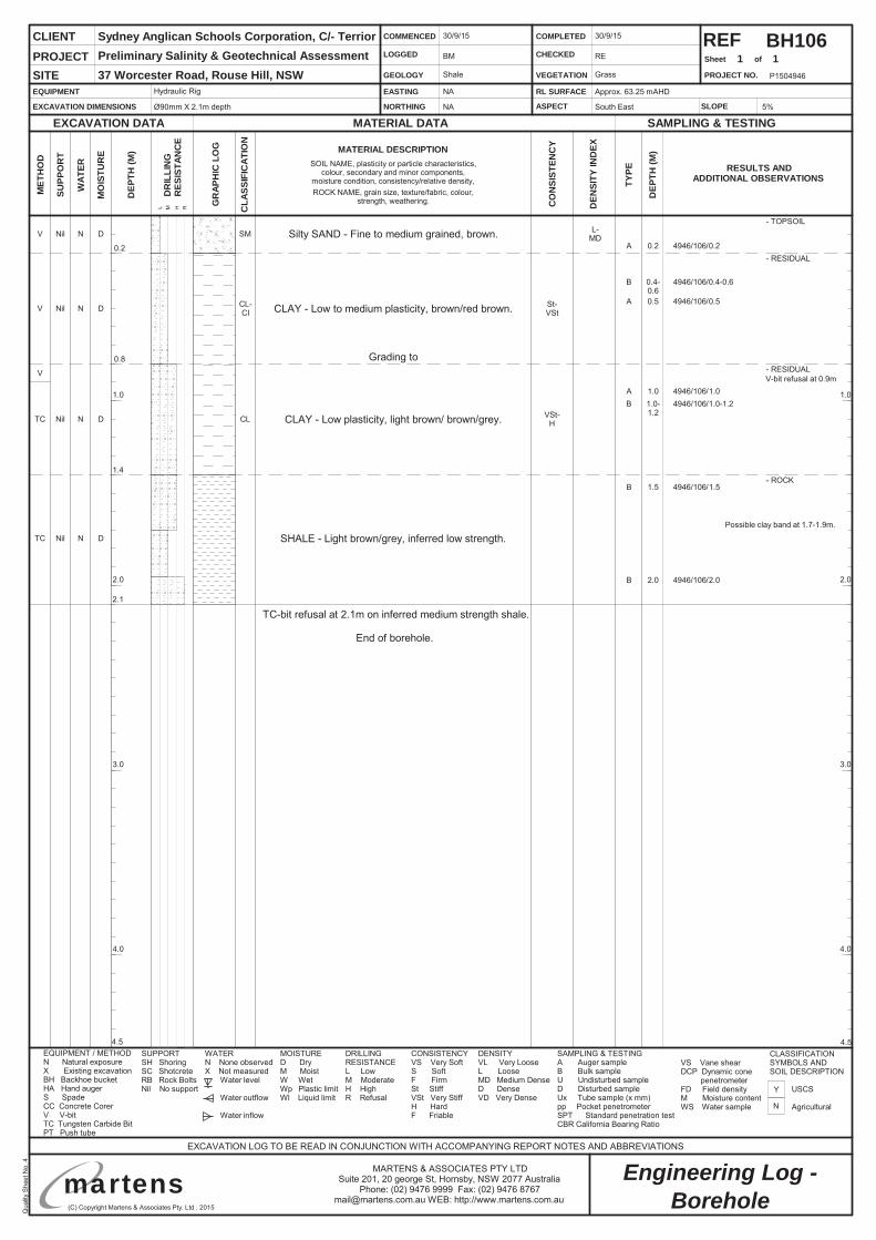
BH106
Silty SAND - Fine to medium grained, brown.V Nil N D SM
0.8- RESIDUAL
0.2- RESIDUAL
N
Y
Borehole
1 1
Hydraulic Rig
Ø90mm X 2.1m depth
NA
NA
Approx. 63.25 mAHD
South East
30/9/15
BM
Shale
30/9/15
RE
Grass
5%
Sydney Anglican Schools Corporation, C/- TerriorPreliminary Salinity & Geotechnical Assessment37 Worcester Road, Rouse Hill, NSW
TC-bit refusal at 2.1m on inferred medium strength shale.
End of borehole.
CLAY - Low plasticity, light brown/ brown/grey.TC Nil N D CL
- TOPSOIL
2.1
1.4- ROCK
SHALE - Light brown/grey, inferred low strength.TC Nil N D
A 0.2 4946/106/0.2
A 0.5 4946/106/0.5CLAY - Low to medium plasticity, brown/red brown.V Nil N D CL-
CI
V-bit refusal at 0.9m
L-MD
VSt-H
St-VSt
B 1.5 4946/106/1.5
Grading to
B 0.4-0.6
4946/106/0.4-0.6
B 1.0-1.2
4946/106/1.0-1.2A 1.0 4946/106/1.0
B 2.0 4946/106/2.0
V
Possible clay band at 1.7-1.9m.
Qua
lityS
heet
No.
4
(C) Copyright Martens & Associates Pty. Ltd . 2015
Engineering Log -MARTENS & ASSOCIATES PTY LTDSuite 201, 20 george St, Hornsby, NSW 2077 Australia
Phone: (02) 9476 9999 Fax: (02) 9476 [email protected] WEB: http://www.martens.com.au
P1504946
1.0
2.0
3.0
4.0
1.0
2.0
3.0
4.0
4.54.5
martens
REFSheet of
SUPP
OR
T
WAT
ER RESULTS ANDADDITIONAL OBSERVATIONS
EXCAVATION DATA
MET
HO
D
MATERIAL DATA SAMPLING & TESTING
EXCAVATION LOG TO BE READ IN CONJUNCTION WITH ACCOMPANYING REPORT NOTES AND ABBREVIATIONS
MO
ISTU
RE
DEP
TH(M
)
TYPE
DEP
TH(M
)
CLIENT
PROJECT NO.
PROJECTSITE
DR
ILLI
NG
RES
ISTA
NC
E
L M H R
EQUIPMENT
EXCAVATION DIMENSIONS
EASTING
NORTHING
RL SURFACE
ASPECT
COMMENCED
LOGGED
GEOLOGY
COMPLETED
CHECKED
VEGETATION
EQUIPMENT / METHODN Natural exposureX Existing excavationBH Backhoe bucketHA Hand augerS SpadeCC Concrete CorerV V-bitTC Tungsten Carbide BitPT Push tube
MOISTURED DryM MoistW WetWp Plastic limitWl Liquid limit
WATERN None observedX Not measured
Water level
Water outflow
Water inflow
SUPPORTSH ShoringSC ShotcreteRB Rock BoltsNil No support
CLASSIFICATIONSYMBOLS ANDSOIL DESCRIPTION
USCS
Agricultural
CONSISTENCYVS Very SoftS SoftF FirmSt StiffVSt Very StiffH HardF Friable
DENSITYVL Very LooseL LooseMD Medium DenseD DenseVD Very Dense
DRILLINGRESISTANCEL LowM ModerateH HighR Refusal
SLOPE
SAMPLING & TESTINGA Auger sampleB Bulk sampleU Undisturbed sampleD Disturbed sampleUx Tube sample (x mm)pp Pocket penetrometerSPT Standard penetration testCBR California Bearing Ratio
VS Vane shearDCP Dynamic cone
penetrometerFD Field densityM Moisture contentWS Water sample
GR
APH
ICLO
G
CLA
SSIF
ICAT
ION
CO
NSI
STEN
CY
DEN
SITY
IND
EXMATERIAL DESCRIPTIONSOIL NAME, plasticity or particle characteristics,
colour, secondary and minor components,moisture condition, consistency/relative density,ROCK NAME, grain size, texture/fabric, colour,
strength, weathering.
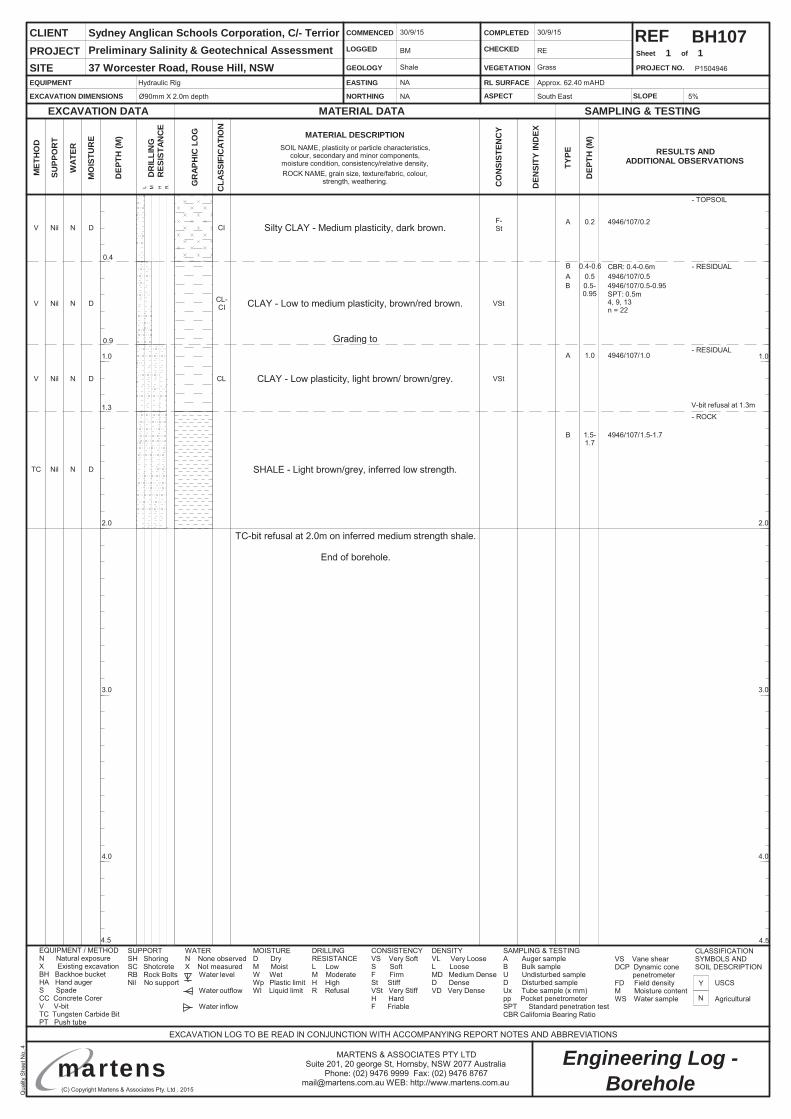
Silty CLAY - Medium plasticity, dark brown.V Nil N D CI
0.9- RESIDUAL
BH107
0.4- RESIDUAL
N
Y
Borehole
1 1
Hydraulic Rig
Ø90mm X 2.0m depth
NA
NA
Approx. 62.40 mAHD
South East
30/9/15
BM
Shale
30/9/15
RE
Grass
5%
Sydney Anglican Schools Corporation, C/- TerriorPreliminary Salinity & Geotechnical Assessment37 Worcester Road, Rouse Hill, NSW
TC-bit refusal at 2.0m on inferred medium strength shale.
End of borehole.
CLAY - Low plasticity, light brown/ brown/grey.V Nil N D CL
- TOPSOIL
1.3- ROCK
SHALE - Light brown/grey, inferred low strength.TC Nil N D
A 0.2 4946/107/0.2
A 0.5 4946/107/0.5
A 1.0 4946/107/1.0
CLAY - Low to medium plasticity, brown/red brown.V Nil N D CL-CI
V-bit refusal at 1.3m
VSt
VSt
B 1.5-1.7
4946/107/1.5-1.7
Grading to
SPT: 0.5m4, 9, 13n = 22
B 0.5-0.95
4946/107/0.5-0.95
CBR: 0.4-0.6mB 0.4-0.6
F-St
Qua
lityS
heet
No.
4
(C) Copyright Martens & Associates Pty. Ltd . 2015
Engineering Log -MARTENS & ASSOCIATES PTY LTDSuite 201, 20 george St, Hornsby, NSW 2077 Australia
Phone: (02) 9476 9999 Fax: (02) 9476 [email protected] WEB: http://www.martens.com.au
P1504946
1.0
2.0
3.0
4.0
1.0
2.0
3.0
4.0
4.54.5
martens
REFSheet of
SUPP
OR
T
WAT
ER RESULTS ANDADDITIONAL OBSERVATIONS
EXCAVATION DATA
MET
HO
D
MATERIAL DATA SAMPLING & TESTING
EXCAVATION LOG TO BE READ IN CONJUNCTION WITH ACCOMPANYING REPORT NOTES AND ABBREVIATIONS
MO
ISTU
RE
DEP
TH(M
)
TYPE
DEP
TH(M
)
CLIENT
PROJECT NO.
PROJECTSITE
DR
ILLI
NG
RES
ISTA
NC
E
L M H R
EQUIPMENT
EXCAVATION DIMENSIONS
EASTING
NORTHING
RL SURFACE
ASPECT
COMMENCED
LOGGED
GEOLOGY
COMPLETED
CHECKED
VEGETATION
EQUIPMENT / METHODN Natural exposureX Existing excavationBH Backhoe bucketHA Hand augerS SpadeCC Concrete CorerV V-bitTC Tungsten Carbide BitPT Push tube
MOISTURED DryM MoistW WetWp Plastic limitWl Liquid limit
WATERN None observedX Not measured
Water level
Water outflow
Water inflow
SUPPORTSH ShoringSC ShotcreteRB Rock BoltsNil No support
CLASSIFICATIONSYMBOLS ANDSOIL DESCRIPTION
USCS
Agricultural
CONSISTENCYVS Very SoftS SoftF FirmSt StiffVSt Very StiffH HardF Friable
DENSITYVL Very LooseL LooseMD Medium DenseD DenseVD Very Dense
DRILLINGRESISTANCEL LowM ModerateH HighR Refusal
SLOPE
SAMPLING & TESTINGA Auger sampleB Bulk sampleU Undisturbed sampleD Disturbed sampleUx Tube sample (x mm)pp Pocket penetrometerSPT Standard penetration testCBR California Bearing Ratio
VS Vane shearDCP Dynamic cone
penetrometerFD Field densityM Moisture contentWS Water sample
GR
APH
ICLO
G
CLA
SSIF
ICAT
ION
CO
NSI
STEN
CY
DEN
SITY
IND
EXMATERIAL DESCRIPTIONSOIL NAME, plasticity or particle characteristics,
colour, secondary and minor components,moisture condition, consistency/relative density,ROCK NAME, grain size, texture/fabric, colour,
strength, weathering.
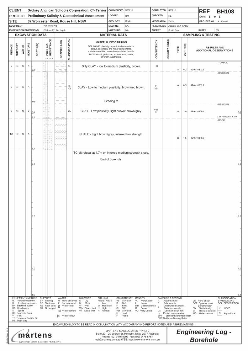
Silty CLAY - low to medium plasticity, brown.V Nil N D CL
0.8- RESIDUAL
BH108
0.2- RESIDUAL
N
Y
Borehole
1 1
Hydraulic Rig
Ø90mm X 1.7m depth
NA
NA
Approx. 65.1 mAHD
South East
30/9/15
BM
Shale
30/9/15
RE
Grass
5%
Sydney Anglican Schools Corporation, C/- TerriorPreliminary Salinity & Geotechnical Assessment37 Worcester Road, Rouse Hill, NSW
TC-bit refusal at 1.7m on inferred medium strength shale.
End of borehole.
CLAY - Low plasticity, light brown/ brown/grey.V Nil N D CL
- TOPSOIL
1.7
1.1- ROCK
SHALE - Light brown/grey, inferred low strength.TC Nil N D
A 0.2 4946/108/0.2
A 0.5 4946/108/0.5
A 1.0 4946/108/1.0
CLAY - Low to medium plasticity, brown/red brown.V Nil N D CL-CI
V-bit refusal at 1.1m
St
VSt-H
F-VSt
B 1.5 4946/108/1.5
Grading to
Qua
lityS
heet
No.
4
(C) Copyright Martens & Associates Pty. Ltd . 2015
Engineering Log -MARTENS & ASSOCIATES PTY LTDSuite 201, 20 george St, Hornsby, NSW 2077 Australia
Phone: (02) 9476 9999 Fax: (02) 9476 [email protected] WEB: http://www.martens.com.au
P1504946
1.0
2.0
3.0
4.0
1.0
2.0
3.0
4.0
4.54.5
martens
REFSheet of
SUPP
OR
T
WAT
ER RESULTS ANDADDITIONAL OBSERVATIONS
EXCAVATION DATA
MET
HO
D
MATERIAL DATA SAMPLING & TESTING
EXCAVATION LOG TO BE READ IN CONJUNCTION WITH ACCOMPANYING REPORT NOTES AND ABBREVIATIONS
MO
ISTU
RE
DEP
TH(M
)
TYPE
DEP
TH(M
)
CLIENT
PROJECT NO.
PROJECTSITE
DR
ILLI
NG
RES
ISTA
NC
E
L M H R
EQUIPMENT
EXCAVATION DIMENSIONS
EASTING
NORTHING
RL SURFACE
ASPECT
COMMENCED
LOGGED
GEOLOGY
COMPLETED
CHECKED
VEGETATION
EQUIPMENT / METHODN Natural exposureX Existing excavationBH Backhoe bucketHA Hand augerS SpadeCC Concrete CorerV V-bitTC Tungsten Carbide BitPT Push tube
MOISTURED DryM MoistW WetWp Plastic limitWl Liquid limit
WATERN None observedX Not measured
Water level
Water outflow
Water inflow
SUPPORTSH ShoringSC ShotcreteRB Rock BoltsNil No support
CLASSIFICATIONSYMBOLS ANDSOIL DESCRIPTION
USCS
Agricultural
CONSISTENCYVS Very SoftS SoftF FirmSt StiffVSt Very StiffH HardF Friable
DENSITYVL Very LooseL LooseMD Medium DenseD DenseVD Very Dense
DRILLINGRESISTANCEL LowM ModerateH HighR Refusal
SLOPE
SAMPLING & TESTINGA Auger sampleB Bulk sampleU Undisturbed sampleD Disturbed sampleUx Tube sample (x mm)pp Pocket penetrometerSPT Standard penetration testCBR California Bearing Ratio
VS Vane shearDCP Dynamic cone
penetrometerFD Field densityM Moisture contentWS Water sample
GR
APH
ICLO
G
CLA
SSIF
ICAT
ION
CO
NSI
STEN
CY
DEN
SITY
IND
EXMATERIAL DESCRIPTIONSOIL NAME, plasticity or particle characteristics,
colour, secondary and minor components,moisture condition, consistency/relative density,ROCK NAME, grain size, texture/fabric, colour,
strength, weathering.
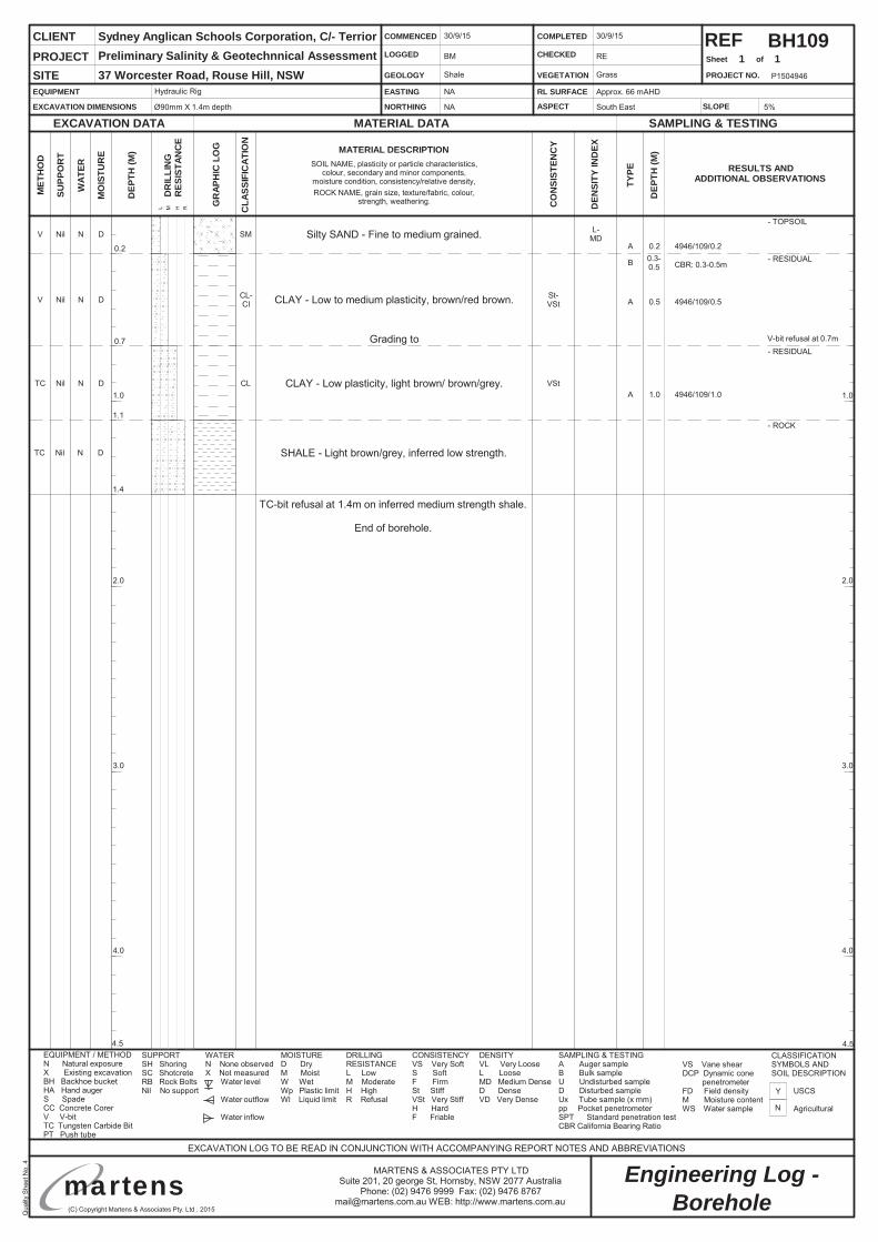
CBR: 0.3-0.5m
Silty SAND - Fine to medium grained.V Nil N D SM
0.7- RESIDUAL
BH109
0.2- RESIDUAL
N
Y
Borehole
1 1
Hydraulic Rig
Ø90mm X 1.4m depth
NA
NA
Approx. 66 mAHD
South East
30/9/15
BM
Shale
30/9/15
RE
Grass
5%
Sydney Anglican Schools Corporation, C/- TerriorPreliminary Salinity & Geotechnnical Assessment37 Worcester Road, Rouse Hill, NSW
TC-bit refusal at 1.4m on inferred medium strength shale.
End of borehole.
CLAY - Low plasticity, light brown/ brown/grey.TC Nil N D CL
- TOPSOIL
1.4
1.1- ROCK
SHALE - Light brown/grey, inferred low strength.TC Nil N D
A 0.2 4946/109/0.2
A 0.5 4946/109/0.5
A 1.0 4946/109/1.0
CLAY - Low to medium plasticity, brown/red brown.V Nil N D CL-CI
V-bit refusal at 0.7m
VSt
St-VSt
Grading to
L-MD
B 0.3-0.5
Qua
lityS
heet
No.
4
(C) Copyright Martens & Associates Pty. Ltd . 2015
Engineering Log -MARTENS & ASSOCIATES PTY LTDSuite 201, 20 george St, Hornsby, NSW 2077 Australia
Phone: (02) 9476 9999 Fax: (02) 9476 [email protected] WEB: http://www.martens.com.au
P1504946
1.0
2.0
3.0
4.0
1.0
2.0
3.0
4.0
4.54.5
martens
REFSheet of
SUPP
OR
T
WAT
ER RESULTS ANDADDITIONAL OBSERVATIONS
EXCAVATION DATA
MET
HO
D
MATERIAL DATA SAMPLING & TESTING
EXCAVATION LOG TO BE READ IN CONJUNCTION WITH ACCOMPANYING REPORT NOTES AND ABBREVIATIONS
MO
ISTU
RE
DEP
TH(M
)
TYPE
DEP
TH(M
)
CLIENT
PROJECT NO.
PROJECTSITE
DR
ILLI
NG
RES
ISTA
NC
E
L M H R
EQUIPMENT
EXCAVATION DIMENSIONS
EASTING
NORTHING
RL SURFACE
ASPECT
COMMENCED
LOGGED
GEOLOGY
COMPLETED
CHECKED
VEGETATION
EQUIPMENT / METHODN Natural exposureX Existing excavationBH Backhoe bucketHA Hand augerS SpadeCC Concrete CorerV V-bitTC Tungsten Carbide BitPT Push tube
MOISTURED DryM MoistW WetWp Plastic limitWl Liquid limit
WATERN None observedX Not measured
Water level
Water outflow
Water inflow
SUPPORTSH ShoringSC ShotcreteRB Rock BoltsNil No support
CLASSIFICATIONSYMBOLS ANDSOIL DESCRIPTION
USCS
Agricultural
CONSISTENCYVS Very SoftS SoftF FirmSt StiffVSt Very StiffH HardF Friable
DENSITYVL Very LooseL LooseMD Medium DenseD DenseVD Very Dense
DRILLINGRESISTANCEL LowM ModerateH HighR Refusal
SLOPE
SAMPLING & TESTINGA Auger sampleB Bulk sampleU Undisturbed sampleD Disturbed sampleUx Tube sample (x mm)pp Pocket penetrometerSPT Standard penetration testCBR California Bearing Ratio
VS Vane shearDCP Dynamic cone
penetrometerFD Field densityM Moisture contentWS Water sample
GR
APH
ICLO
G
CLA
SSIF
ICAT
ION
CO
NSI
STEN
CY
DEN
SITY
IND
EXMATERIAL DESCRIPTIONSOIL NAME, plasticity or particle characteristics,
colour, secondary and minor components,moisture condition, consistency/relative density,ROCK NAME, grain size, texture/fabric, colour,
strength, weathering.
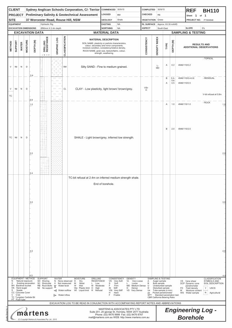
BH110
Silty SAND - Fine to medium grained.V Nil N D SM
0.4- RESIDUAL
N
Y
Borehole
1 1
Hydraulic Rig
Ø90mm X 2.4m depth
NA
NA
Approx. 63.35 mAHD
South East
30/9/15
BM
Shale
30/9/15
RE
Grass
5%
Sydney Anglican Schools Corporation, C/- TerriorPreliminary Salinity & Geotechnical Assessment37 Worcester Road, Rouse Hill, NSW
TC-bit refusal at 2.4m on inferred medium strength shale.
End of borehole.
CLAY - Low plasticity, light brown/ brown/grey.V Nil N D CL
- TOPSOIL
2.4
0.9- ROCK
SHALE - Light brown/grey, inferred low strength.TC Nil N D
A 0.2 4946/110/0.2
A 0.5 4946/110/0.5
A 1.0 4946/110/1.0
V-bit refusal at 0.8m
L-MD
VSt-H
B 2.0 4946/110/2.0
B 0.4-0.6
4946/110/0.4-0.6
TC
Qua
lityS
heet
No.
4
(C) Copyright Martens & Associates Pty. Ltd . 2015
Engineering Log -MARTENS & ASSOCIATES PTY LTDSuite 201, 20 george St, Hornsby, NSW 2077 Australia
Phone: (02) 9476 9999 Fax: (02) 9476 [email protected] WEB: http://www.martens.com.au
P1504946
1.0
2.0
3.0
4.0
1.0
2.0
3.0
4.0
4.54.5
martens
REFSheet of
SUPP
OR
T
WAT
ER RESULTS ANDADDITIONAL OBSERVATIONS
EXCAVATION DATA
MET
HO
D
MATERIAL DATA SAMPLING & TESTING
EXCAVATION LOG TO BE READ IN CONJUNCTION WITH ACCOMPANYING REPORT NOTES AND ABBREVIATIONS
MO
ISTU
RE
DEP
TH(M
)
TYPE
DEP
TH(M
)
CLIENT
PROJECT NO.
PROJECTSITE
DR
ILLI
NG
RES
ISTA
NC
E
L M H R
EQUIPMENT
EXCAVATION DIMENSIONS
EASTING
NORTHING
RL SURFACE
ASPECT
COMMENCED
LOGGED
GEOLOGY
COMPLETED
CHECKED
VEGETATION
EQUIPMENT / METHODN Natural exposureX Existing excavationBH Backhoe bucketHA Hand augerS SpadeCC Concrete CorerV V-bitTC Tungsten Carbide BitPT Push tube
MOISTURED DryM MoistW WetWp Plastic limitWl Liquid limit
WATERN None observedX Not measured
Water level
Water outflow
Water inflow
SUPPORTSH ShoringSC ShotcreteRB Rock BoltsNil No support
CLASSIFICATIONSYMBOLS ANDSOIL DESCRIPTION
USCS
Agricultural
CONSISTENCYVS Very SoftS SoftF FirmSt StiffVSt Very StiffH HardF Friable
DENSITYVL Very LooseL LooseMD Medium DenseD DenseVD Very Dense
DRILLINGRESISTANCEL LowM ModerateH HighR Refusal
SLOPE
SAMPLING & TESTINGA Auger sampleB Bulk sampleU Undisturbed sampleD Disturbed sampleUx Tube sample (x mm)pp Pocket penetrometerSPT Standard penetration testCBR California Bearing Ratio
VS Vane shearDCP Dynamic cone
penetrometerFD Field densityM Moisture contentWS Water sample
GR
APH
ICLO
G
CLA
SSIF
ICAT
ION
CO
NSI
STEN
CY
DEN
SITY
IND
EXMATERIAL DESCRIPTIONSOIL NAME, plasticity or particle characteristics,
colour, secondary and minor components,moisture condition, consistency/relative density,ROCK NAME, grain size, texture/fabric, colour,
strength, weathering.
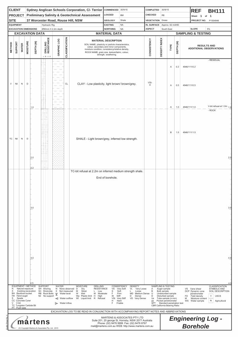
BH111
N
Y
Borehole
1 1
Hydraulic Rig
Ø90mm X 2.2m depth
NA
NA
Approx. 62 mAHD
South East
30/9/15
BM
Shale
30/9/15
RE
Grass
5%
Sydney Anglican Schools Corporation, C/- TerriorPreliminary Salinity & Geotechnical Assessment37 Worcester Road, Rouse Hill, NSW
TC-bit refusal at 2.2m on inferred medium strength shale.
End of borehole.
CLAY - Low plasticity, light brown/ brown/grey.V Nil N D CL
- RESIDUAL
2.2
- ROCK
SHALE - Light brown/grey, inferred low strength.TC Nil N D
A 0.2 4946/111/0.2
A 0.5 4946/111/0.5
A 1.0 4946/111/1.0 V-bit refusal at 1.0m
VSt-H
B 1.5 4946/111/1.5
martens
Preliminary Salinity and Geotechnical Assessment: 37 Worcester Road, Rouse Hill, NSW.
P1504946JR01V02 – August 2017
Page 49
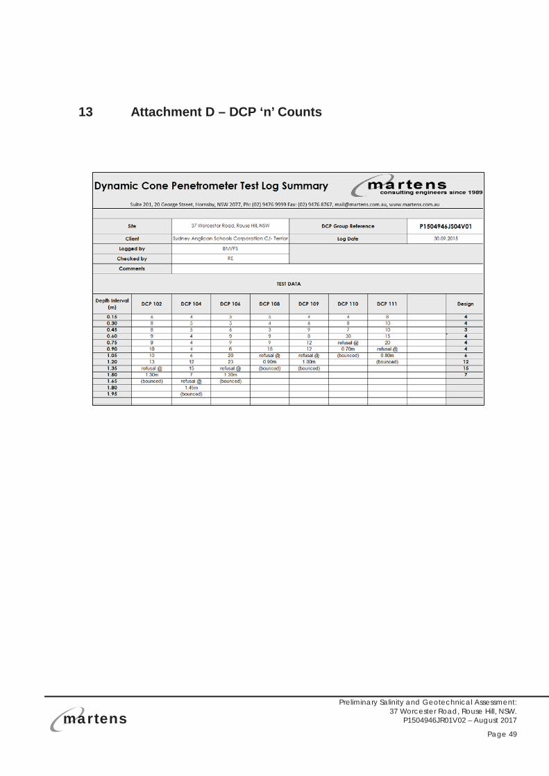
13 Attachment D – DCP ‘n’ Counts
martens
Preliminary Salinity and Geotechnical Assessment: 37 Worcester Road, Rouse Hill, NSW.
P1504946JR01V02 – August 2017
Page 50
14 Attachment E – Salinity Laboratory Report
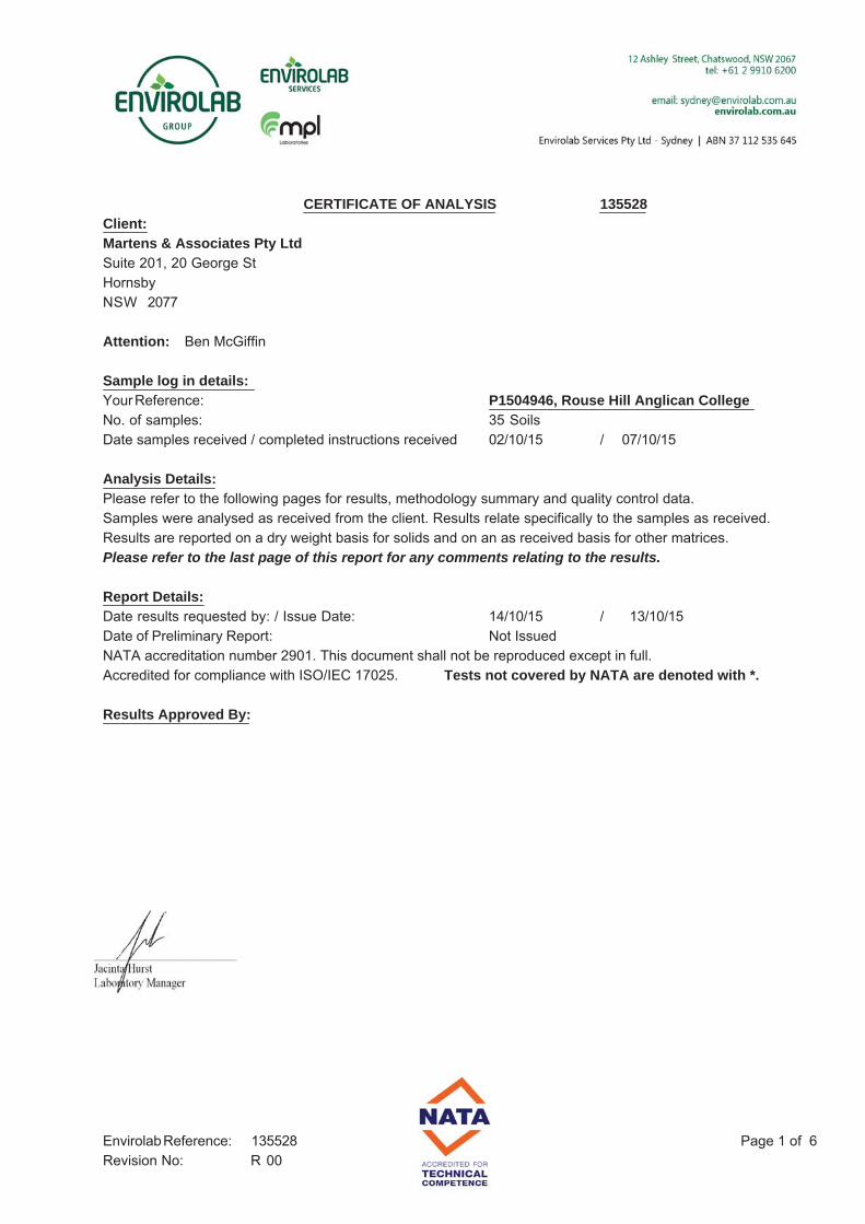
CERTIFICATE OF ANALYSIS 135528Client:Martens & Associates Pty LtdSuite 201, 20 George StHornsbyNSW 2077
Attention: Ben McGiffin
Sample log in details:Your Reference: P1504946, Rouse Hill Anglican CollegeNo. of samples: 35 SoilsDate samples received / completed instructions received 02/10/15 / 07/10/15
Analysis Details:Please refer to the following pages for results, methodology summary and quality control data.Samples were analysed as received from the client. Results relate specifically to the samples as received.Results are reported on a dry weight basis for solids and on an as received basis for other matrices.Please refer to the last page of this report for any comments relating to the results.
Report Details:Date results requested by: / Issue Date: 14/10/15 / 13/10/15Date of Preliminary Report: Not IssuedNATA accreditation number 2901. This document shall not be reproduced except in full.Accredited for compliance with ISO/IEC 17025. Tests not covered by NATA are denoted with *.
Results Approved By:
Page 1 of 6Envirolab Reference: 135528Revision No: R 00
Client Reference: P1504946, Rouse Hill Anglican College
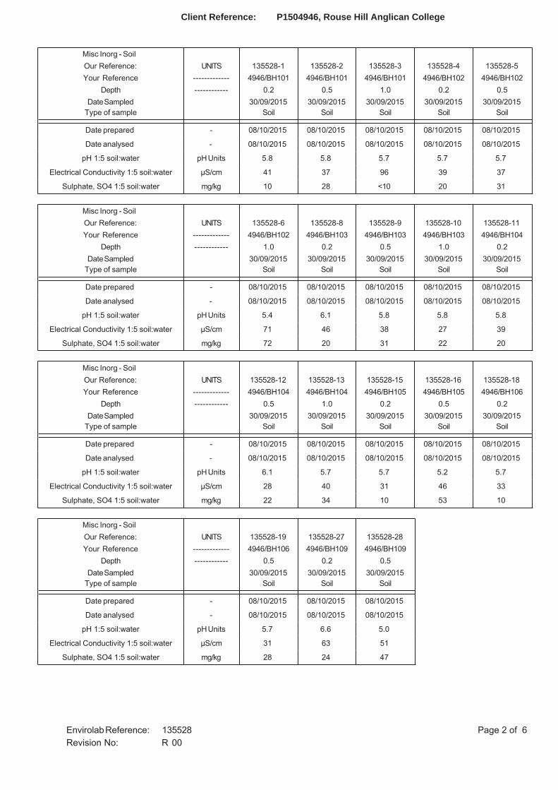
Misc Inorg - Soil Our Reference: UNITS 135528-1 135528-2 135528-3 135528-4 135528-5Your Reference ------------- 4946/BH101 4946/BH101 4946/BH101 4946/BH102 4946/BH102
Depth ------------ 0.2 0.5 1.0 0.2 0.5Date Sampled
Type of sample30/09/2015
Soil30/09/2015
Soil30/09/2015
Soil30/09/2015
Soil30/09/2015
Soil
Date prepared - 08/10/2015 08/10/2015 08/10/2015 08/10/2015 08/10/2015
Date analysed - 08/10/2015 08/10/2015 08/10/2015 08/10/2015 08/10/2015
pH 1:5 soil:water pH Units 5.8 5.8 5.7 5.7 5.7
Electrical Conductivity 1:5 soil:water μS/cm 41 37 96 39 37
Sulphate, SO4 1:5 soil:water mg/kg 10 28 <10 20 31
Misc Inorg - Soil Our Reference: UNITS 135528-6 135528-8 135528-9 135528-10 135528-11Your Reference ------------- 4946/BH102 4946/BH103 4946/BH103 4946/BH103 4946/BH104
Depth ------------ 1.0 0.2 0.5 1.0 0.2Date Sampled
Type of sample30/09/2015
Soil30/09/2015
Soil30/09/2015
Soil30/09/2015
Soil30/09/2015
Soil
Date prepared - 08/10/2015 08/10/2015 08/10/2015 08/10/2015 08/10/2015
Date analysed - 08/10/2015 08/10/2015 08/10/2015 08/10/2015 08/10/2015
pH 1:5 soil:water pH Units 5.4 6.1 5.8 5.8 5.8
Electrical Conductivity 1:5 soil:water μS/cm 71 46 38 27 39
Sulphate, SO4 1:5 soil:water mg/kg 72 20 31 22 20
Misc Inorg - Soil Our Reference: UNITS 135528-12 135528-13 135528-15 135528-16 135528-18Your Reference ------------- 4946/BH104 4946/BH104 4946/BH105 4946/BH105 4946/BH106
Depth ------------ 0.5 1.0 0.2 0.5 0.2Date Sampled
Type of sample30/09/2015
Soil30/09/2015
Soil30/09/2015
Soil30/09/2015
Soil30/09/2015
Soil
Date prepared - 08/10/2015 08/10/2015 08/10/2015 08/10/2015 08/10/2015
Date analysed - 08/10/2015 08/10/2015 08/10/2015 08/10/2015 08/10/2015
pH 1:5 soil:water pH Units 6.1 5.7 5.7 5.2 5.7
Electrical Conductivity 1:5 soil:water μS/cm 28 40 31 46 33
Sulphate, SO4 1:5 soil:water mg/kg 22 34 10 53 10
Misc Inorg - Soil Our Reference: UNITS 135528-19 135528-27 135528-28Your Reference ------------- 4946/BH106 4946/BH109 4946/BH109
Depth ------------ 0.5 0.2 0.5Date Sampled
Type of sample30/09/2015
Soil30/09/2015
Soil30/09/2015
Soil
Date prepared - 08/10/2015 08/10/2015 08/10/2015
Date analysed - 08/10/2015 08/10/2015 08/10/2015
pH 1:5 soil:water pH Units 5.7 6.6 5.0
Electrical Conductivity 1:5 soil:water μS/cm 31 63 51
Sulphate, SO4 1:5 soil:water mg/kg 28 24 47
Page 2 of 6Envirolab Reference: 135528Revision No: R 00

Client Reference: P1504946, Rouse Hill Anglican College
Method ID Methodology Summary
Inorg-001 pH - Measured using pH meter and electrode in accordance with APHA latest edition, 4500-H+. Please note that the results for water analyses are indicative only, as analysis outside of the APHA storage times.
Inorg-002 Conductivity and Salinity - measured using a conductivity cell at 25oC in accordance with APHA latest edition 2510 and Rayment & Lyons.
Inorg-081 Anions - a range of Anions are determined by Ion Chromatography, in accordance with APHA latest edition, 4110-B.
Page 3 of 6Envirolab Reference: 135528Revision No: R 00
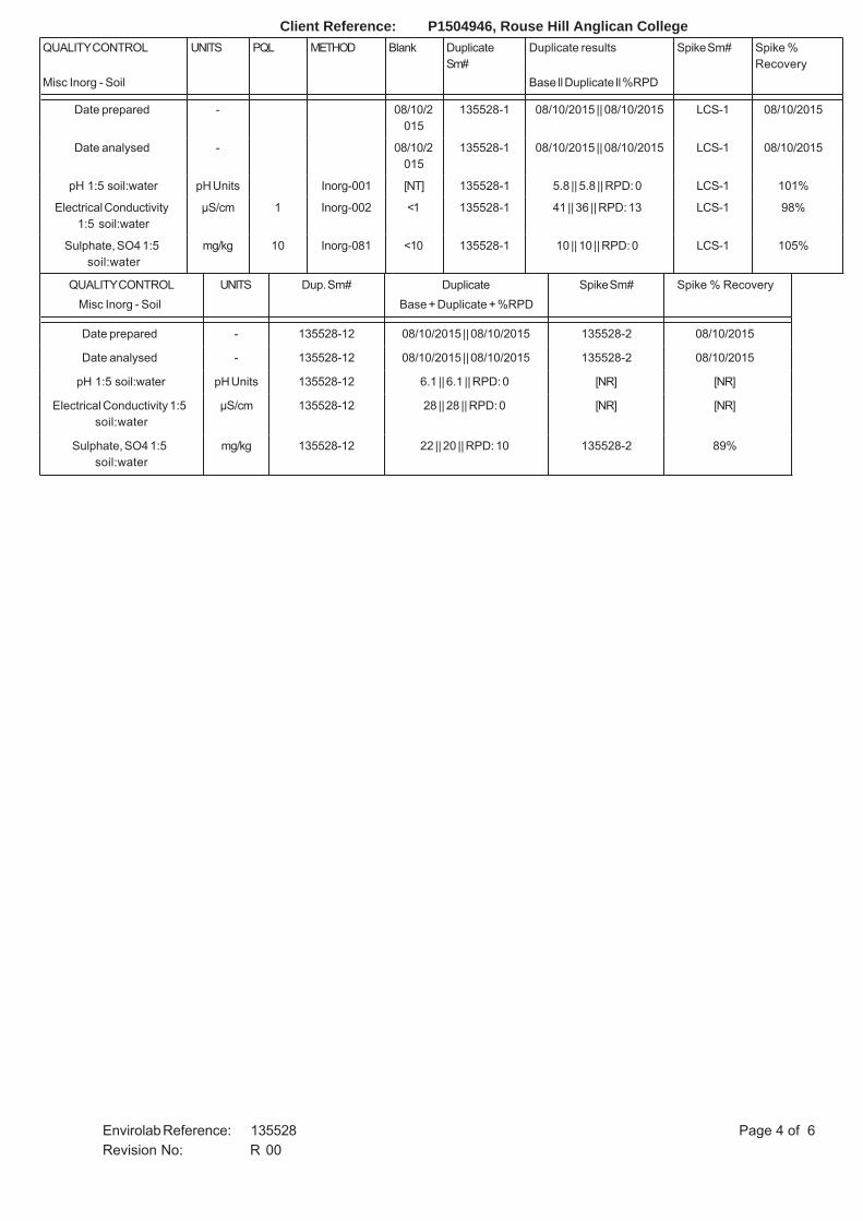
Client Reference: P1504946, Rouse Hill Anglican CollegeQUALITY CONTROL UNITS PQL METHOD Blank Duplicate
Sm#Duplicate results Spike Sm# Spike %
RecoveryMisc Inorg - Soil Base ll Duplicate ll %RPD
Date prepared - 08/10/2015
135528-1 08/10/2015 || 08/10/2015 LCS-1 08/10/2015
Date analysed - 08/10/2015
135528-1 08/10/2015 || 08/10/2015 LCS-1 08/10/2015
pH 1:5 soil:water pH Units Inorg-001 [NT] 135528-1 5.8 || 5.8 || RPD: 0 LCS-1 101%
Electrical Conductivity 1:5 soil:water
μS/cm 1 Inorg-002 <1 135528-1 41 || 36 || RPD: 13 LCS-1 98%
Sulphate, SO4 1:5 soil:water
mg/kg 10 Inorg-081 <10 135528-1 10 || 10 || RPD: 0 LCS-1 105%
QUALITY CONTROL UNITS Dup. Sm# Duplicate Spike Sm# Spike % RecoveryMisc Inorg - Soil Base + Duplicate + %RPD
Date prepared - 135528-12 08/10/2015 || 08/10/2015 135528-2 08/10/2015
Date analysed - 135528-12 08/10/2015 || 08/10/2015 135528-2 08/10/2015
pH 1:5 soil:water pH Units 135528-12 6.1 || 6.1 || RPD: 0 [NR] [NR]
Electrical Conductivity 1:5 soil:water
μS/cm 135528-12 28 || 28 || RPD: 0 [NR] [NR]
Sulphate, SO4 1:5 soil:water
mg/kg 135528-12 22 || 20 || RPD: 10 135528-2 89%
Page 4 of 6Envirolab Reference: 135528Revision No: R 00
Client Reference: P1504946, Rouse Hill Anglican College
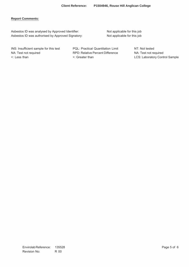
Report Comments:
Asbestos ID was analysed by Approved Identifier: Not applicable for this jobAsbestos ID was authorised by Approved Signatory: Not applicable for this job
INS: Insufficient sample for this test PQL: Practical Quantitation Limit NT: Not testedNA: Test not required RPD: Relative Percent Difference NA: Test not required<: Less than >: Greater than LCS: Laboratory Control Sample
Page 5 of 6Envirolab Reference: 135528Revision No: R 00
Client Reference: P1504946, Rouse Hill Anglican College
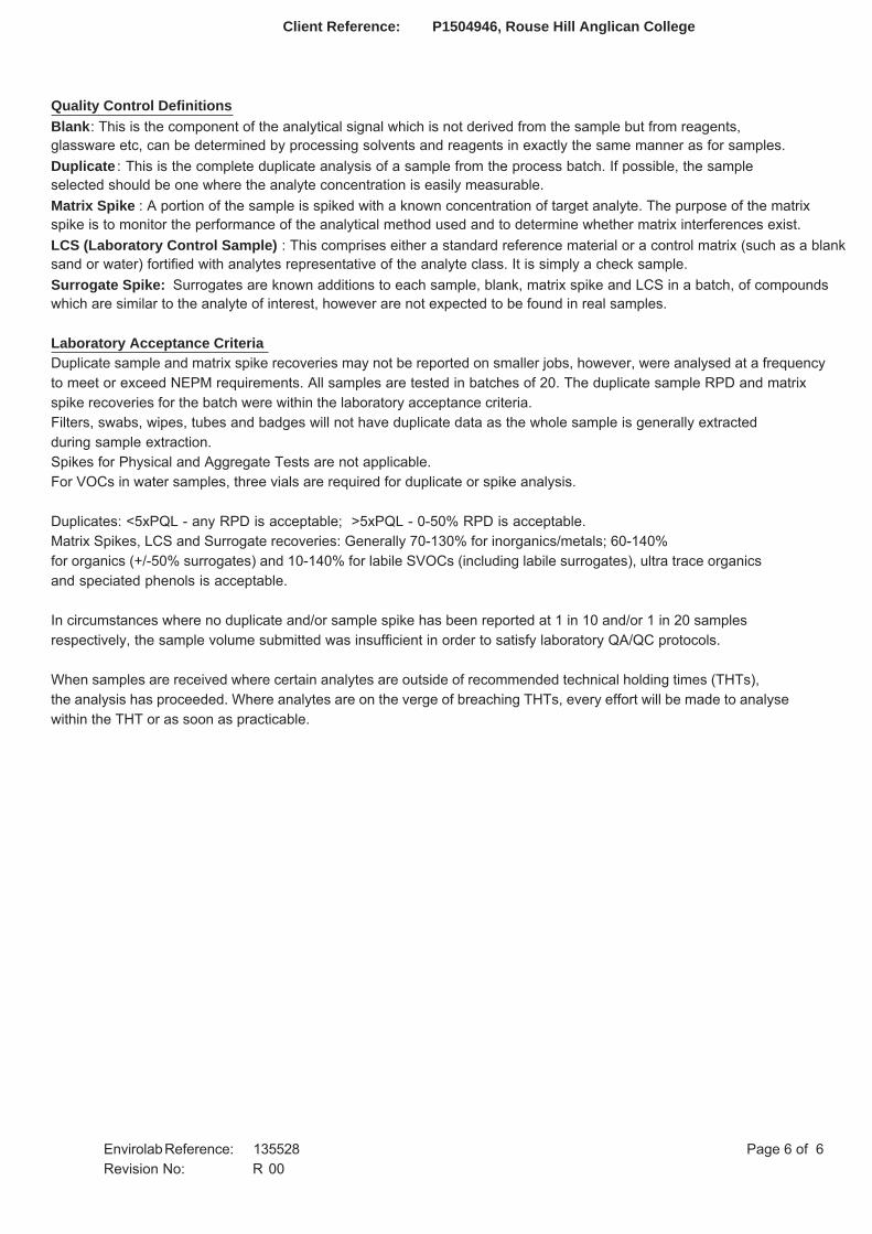
Quality Control DefinitionsBlank: This is the component of the analytical signal which is not derived from the sample but from reagents, glassware etc, can be determined by processing solvents and reagents in exactly the same manner as for samples. Duplicate : This is the complete duplicate analysis of a sample from the process batch. If possible, the sampleselected should be one where the analyte concentration is easily measurable. Matrix Spike : A portion of the sample is spiked with a known concentration of target analyte. The purpose of the matrix spike is to monitor the performance of the analytical method used and to determine whether matrix interferences exist. LCS (Laboratory Control Sample) : This comprises either a standard reference material or a control matrix (such as a blanksand or water) fortified with analytes representative of the analyte class. It is simply a check sample. Surrogate Spike: Surrogates are known additions to each sample, blank, matrix spike and LCS in a batch, of compoundswhich are similar to the analyte of interest, however are not expected to be found in real samples.
Laboratory Acceptance CriteriaDuplicate sample and matrix spike recoveries may not be reported on smaller jobs, however, were analysed at a frequencyto meet or exceed NEPM requirements. All samples are tested in batches of 20. The duplicate sample RPD and matrixspike recoveries for the batch were within the laboratory acceptance criteria.Filters, swabs, wipes, tubes and badges will not have duplicate data as the whole sample is generally extracted during sample extraction.Spikes for Physical and Aggregate Tests are not applicable.For VOCs in water samples, three vials are required for duplicate or spike analysis.
Duplicates: <5xPQL - any RPD is acceptable; >5xPQL - 0-50% RPD is acceptable.Matrix Spikes, LCS and Surrogate recoveries: Generally 70-130% for inorganics/metals; 60-140%for organics (+/-50% surrogates) and 10-140% for labile SVOCs (including labile surrogates), ultra trace organicsand speciated phenols is acceptable.
In circumstances where no duplicate and/or sample spike has been reported at 1 in 10 and/or 1 in 20 samples respectively, the sample volume submitted was insufficient in order to satisfy laboratory QA/QC protocols.
When samples are received where certain analytes are outside of recommended technical holding times (THTs), the analysis has proceeded. Where analytes are on the verge of breaching THTs, every effort will be made to analyse within the THT or as soon as practicable.
Page 6 of 6Envirolab Reference: 135528Revision No: R 00
martens
Preliminary Salinity and Geotechnical Assessment: 37 Worcester Road, Rouse Hill, NSW.
P1504946JR01V02 – August 2017
Page 57
15 Attachment F – CBR and Atterberg Limits Laboratory
Reports
ABN: 25 131 532 020
Sydney: 12/1 Boden Road Seven Hills NSW 2147 | PO Box 45 Pendle Hill NSW 2145 Ph: (02) 9674 7711 | Fax: (02) 9674 7755 | Email: [email protected]
Customer: Job number: 15-0092
Project: P1504946 Report number: 2
Location: Page: 1 of 1
Sampling method: Samples tested as received Test method(s):
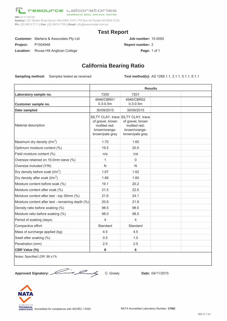
7200 72014946/CBR01
0.3-0.5m4946/CBR02
0.3-0.5m #N/A #N/A
30/09/2015 30/09/2015 #N/A #N/A
SILTY CLAY, trace of gravel, brown
mottled red-brown/orange-
brown/pale grey
SILTY CLAY, trace of gravel, brown
mottled red-brown/orange-
brown/pale grey
#N/A #N/A
1.70 1.65
19.5 20.5
n/a n/a
1 0
N N
1.67 1.62
1.66 1.60
19.1 20.2
21.5 22.5
21.6 24.1
20.8 21.8
98.5 98.5
98.0 98.5
4 4
Standard Standard
4.5 4.5
0.5 1.0
2.5 2.5
8 6
Approved Signatory: C. Greely Date: 04/11/2015
Accredited for compliance with ISO/IEC 17025. NATA Accredited Laboratory Number: 17062
R20.v7/ 1 of 1
Notes: Specified LDR: 98 ±1%
AS 1289.1.1, 2.1.1, 5.1.1, 6.1.1
CBR Value (%)
Compactive effort
Swell after soaking (%)
Penetration (mm)
Dry density after soak (t/m3)
Period of soaking (days)
Mass of surcharge applied (kg)
Density ratio before soaking (%)
Moisture ratio before soaking (%)
Moisture content after soak (%)
Moisture content after test - remaining depth (%)
Moisture content after test - top 30mm (%)
Moisture content before soak (%)
Test Report
California Bearing Ratio
Material description
Dry density before soak (t/m3)
Laboratory sample no.
Maximum dry density (t/m3)
Optimum moisture content (%)
Oversize retained on 19.0mm sieve (%)
Field moisture content (%)
Oversize included (Y/N)
Customer sample no.
Date sampled
Results
Martens & Associates Pty Ltd
Rouse Hill Anglican College
ABN: 25 131 532 020
ABN: 25 131 532 020
Sydney: 12/1 Boden Road Seven Hills NSW 2147 | PO Box 45 Pendle Hill NSW 2145 Ph: (02) 9674 7711 | Fax: (02) 9674 7755 | Email: [email protected]
Customer: Job number: 15-0092
Project: Report number: 1
Location: Page: 1 of 1
Sampling method: Samples tested as received Test method(s):.3.4.1
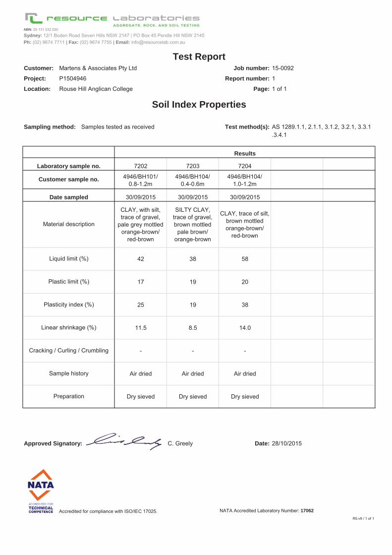
7202 7203 7204
4946/BH101/ 0.8-1.2m
4946/BH104/ 0.4-0.6m
4946/BH104/ 1.0-1.2m #N/A #N/A
30/09/2015 30/09/2015 30/09/2015 #N/A #N/A
CLAY, with silt, trace of gravel,
pale grey mottled orange-brown/
red-brown
SILTY CLAY, trace of gravel, brown mottled
pale brown/ orange-brown
CLAY, trace of silt, brown mottled orange-brown/
red-brown
#N/A #N/A
42 38 58
17 19 20
25 19 38
11.5 8.5 14.0
- - -
Air dried Air dried Air dried
Dry sieved Dry sieved Dry sieved
Approved Signatory: C. Greely Date: 28/10/2015
Accredited for compliance with ISO/IEC 17025. NATA Accredited Laboratory Number: 17062R5.v9 / 1 of 1
Test Report
Soil Index Properties
Results
Liquid limit (%)
Plastic limit (%)
Material description
AS 1289.1.1, 2.1.1, 3.1.2, 3.2.1, 3.3.1
Laboratory sample no.
Customer sample no.
Date sampled
Martens & Associates Pty Ltd
P1504946
Rouse Hill Anglican College
Cracking / Curling / Crumbling
Sample history
Preparation
Plasticity index (%)
Linear shrinkage (%)
ABN: 25 131 532 020
martens
Preliminary Salinity and Geotechnical Assessment: 37 Worcester Road, Rouse Hill, NSW.
P1504946JR01V02 – August 2017
Page 60
16 Attachment G – CSIRO Sheet BTF 18

martens
Preliminary Salinity and Geotechnical Assessment: 37 Worcester Road, Rouse Hill, NSW.
P1504946JR01V02 – August 2017
Page 65
17 Attachment H – Notes About This Report
ma
rten
s
cons
ultin
g en
gine
ers
Subsurface conditions cause more construction problems than any other factor. These notes have been prepared by Martens to help you interpret and understand the limitations of your report. Not all of course, are necessarily relevant to all reports, but are included as general reference. Engineering Reports - Limitations Geotechnical reports are based on information gained from limited sub-surface site testing and sampling, supplemented by knowledge of local geology and experience. For this reason, they must be regarded as interpretative rather than factual documents, limited to some extent by the scope of information on which they rely. Engineering Reports – Project Specific Criteria Engineering reports are prepared by qualified personnel and are based on the information obtained, on current engineering standards of interpretation and analysis, and on the basis of your unique project specific requirements as understood by Martens. Project criteria typically include the general nature of the project; its size and configuration; the location of any structures on the site; other site improvements; the presence of underground utilities; and the additional risk imposed by scope-of-service limitations imposed by the Client. Where the report has been prepared for a specific design proposal (eg. a three storey building), the information and interpretation may not be relative if the design proposal is changed (eg. to a twenty storey building). Your report should not be relied upon if there are changes to the project without first asking Martens to assess how factors that changed subsequent to the date of the report affect the report’s recommendations. Martens will not accept responsibility for problems that may occur due to design changes if they are not consulted. Engineering Reports – Recommendations Your report is based on the assumption that the site conditions as revealed through selective point sampling are indicative of actual conditions throughout an area. This assumption often cannot be substantiated until project implementation has commenced and therefore your site investigation report recommendations should only be regarded as preliminary. Only Martens, who prepared the report, are fully familiar with the background information needed to assess whether or not the report’s recommendations are valid and whether or not changes should be considered as the project develops. If another party undertakes the implementation of the recommendations of this report there is a risk that the report will be misinterpreted and Martens cannot be held responsible for such misinterpretation.
Engineering Reports – Use For Tendering Purposes Where information obtained from this investigation is provided for tendering purposes, Martens recommend that all information, including the written report and discussion, be made available. In circumstances where the discussion or comments section is not relevant to the contractual situation, it may be appropriate to prepare a specially edited document. Attention is drawn to the document ‘Guidelines for the Provision of Geotechnical Information in Tender Documents’, published by the Institution of Engineers, Australia. The Company would be pleased to assist in this regard and/or to make additional report copies available for contract purposes at a nominal charge. Engineering Reports – Data The report as a whole presents the findings of the site assessment and the report should not be copied in part or altered in any way. Logs, figures, drawings etc are customarily included in a Martens report and are developed by scientists, engineers or geologists based on their interpretation of field logs (assembled by field personnel) and laboratory evaluation of field samples. These data should not under any circumstances be redrawn for inclusion in other documents or separated from the report in any way. Engineering Reports – Other Projects To avoid misuse of the information contained in your report it is recommended that you confer with Martens before passing your report on to another party who may not be familiar with the background and the purpose of the report. Your report should not be applied to any project other than that originally specified at the time the report was issued. Subsurface Conditions - General Every care is taken with the report as it relates to interpretation of subsurface conditions, discussion of geotechnical aspects, relevant standards and recommendations or suggestions for design and construction. However, the Company cannot always anticipate or assume responsibility for: o Unexpected variations in ground conditions -
the potential for will depend partly on test point (eg. excavation or borehole) spacing and sampling frequency which are often limited by project imposed budgetary constraints.
o Changes in guidelines, standards and policy or interpretation of guidelines, standards and
Important Information About Your Report
ma
rten
s
cons
ultin
g en
gine
ers
policy by statutory authorities.
o The actions of contractors responding to commercial pressures.
o Actual conditions differing somewhat from those inferred to exist, because no professional, no matter how qualified, can reveal precisely what is hidden by earth, rock and time. The actual interface between materials may be far more gradual or abrupt than assumed based on the facts obtained. Nothing can be done to change the actual site conditions which exist, but steps can be taken to reduce the impact of unexpected conditions
If these conditions occur, the Company will be pleased to assist with investigation or advice to resolve the matter. Subsurface Conditions - Changes Natural processes and the activity of man create subsurface conditions. For example, water levels can vary with time, fill may be placed on a site and pollutants may migrate with time. Reports are based on conditions which existed at the time of the subsurface exploration. Decisions should not be based on a report whose adequacy may have been affected by time. If an extended period of time has elapsed since the report was prepared, consult Martens to be advised how time may have impacted on the project. Subsurface Conditions - Site Anomalies In the event that conditions encountered on site during construction appear to vary from those that were expected from the information contained in the report, the Company requests that it immediately be notified. Most problems are much more readily resolved at the time when conditions are exposed, rather than at some later stage well after the event. Report Use By Other Design Professionals To avoid potentially costly misinterpretations when other design professionals develop their plans based on a report, retain Martens to work with other project professionals who are affected by the report. This may involve Martens explaining the report design implications and then reviewing plans and specifications produced to see how they have incorporated the report findings.
Subsurface Conditions - Geoenvironmental Issues Your report generally does not relate to any findings, conclusions, or recommendations about the potential for hazardous or contaminated materials existing at the site unless specifically required to do so as part of the Company’s proposal for works. Specific sampling guidelines and specialist equipment, techniques and personnel are typically used to perform geoenvironmental or site contamination assessments. Contamination can create major health, safety and environmental risks. If you have no information about the potential for your site to be contaminated or create an environmental hazard, you are advised to contact Martens for information relating to such matters. Responsibility Geotechnical reporting relies on interpretation of factual information based on professional judgment and opinion and has an inherent level of uncertainty attached to it and is typically far less exact than the design disciplines. This has often resulted in claims being lodged against consultants, which are unfounded. To help prevent this problem, a number of clauses have been developed for use in contracts, reports and other documents. Responsibility clauses do not transfer appropriate liabilities from Martens to other parties but are included to identify where Martens’ responsibilities begin and end. Their use is intended to help all parties involved to recognize their individual responsibilities. Read all documents from Martens closely and do not hesitate to ask any questions you may have. Site Inspections Martens will always be pleased to provide engineering inspection services for aspects of work to which this report is related. This could range from a site visit to confirm that conditions exposed are as expected, to full time engineering presence on site. Martens is familiar with a variety of techniques and approaches that can be used to help reduce risks for all parties to a project, from design to construction.
ma
rten
s
cons
ultin
g en
gine
ers
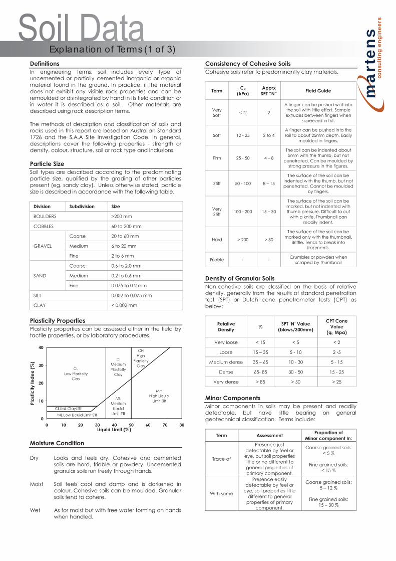
Definitions In engineering terms, soil includes every type of uncemented or partially cemented inorganic or organic material found in the ground. In practice, if the material does not exhibit any visible rock properties and can be remoulded or disintegrated by hand in its field condition or in water it is described as a soil. Other materials are described using rock description terms. The methods of description and classification of soils and rocks used in this report are based on Australian Standard 1726 and the S.A.A Site Investigation Code. In general, descriptions cover the following properties - strength or density, colour, structure, soil or rock type and inclusions. Particle Size Soil types are described according to the predominating particle size, qualified by the grading of other particles present (eg. sandy clay). Unless otherwise stated, particle size is described in accordance with the following table.
Division Subdivision Size
BOULDERS >200 mm
COBBLES 60 to 200 mm
GRAVEL
Coarse 20 to 60 mm
Medium 6 to 20 mm
Fine 2 to 6 mm
SAND
Coarse 0.6 to 2.0 mm
Medium 0.2 to 0.6 mm
Fine 0.075 to 0.2 mm
SILT 0.002 to 0.075 mm
CLAY < 0.002 mm
Plasticity Properties Plasticity properties can be assessed either in the field by tactile properties, or by laboratory procedures.
Moisture Condition Dry Looks and feels dry. Cohesive and cemented
soils are hard, friable or powdery. Uncemented granular soils run freely through hands.
Moist Soil feels cool and damp and is darkened in
colour. Cohesive soils can be moulded. Granular soils tend to cohere.
Wet As for moist but with free water forming on hands
when handled.
Consistency of Cohesive Soils Cohesive soils refer to predominantly clay materials.
Term Cu (kPa)
Apprx SPT “N” Field Guide
Very Soft <12 2
A finger can be pushed well into the soil with little effort. Sample extrudes between fingers when
squeezed in fist.
Soft 12 - 25 2 to 4 A finger can be pushed into the soil to about 25mm depth. Easily
moulded in fingers.
Firm 25 - 50 4 – 8
The soil can be indented about 5mm with the thumb, but not
penetrated. Can be moulded by strong pressure in the figures.
Stiff 50 - 100 8 – 15
The surface of the soil can be indented with the thumb, but not penetrated. Cannot be moulded
by fingers.
Very Stiff 100 - 200 15 – 30
The surface of the soil can be marked, but not indented with thumb pressure. Difficult to cut
with a knife. Thumbnail can readily indent.
Hard > 200 > 30
The surface of the soil can be marked only with the thumbnail.
Brittle. Tends to break into fragments.
Friable - - Crumbles or powders when scraped by thumbnail
Density of Granular Soils Non-cohesive soils are classified on the basis of relative density, generally from the results of standard penetration test (SPT) or Dutch cone penetrometer tests (CPT) as below:
Relative Density % SPT ‘N’ Value
(blows/300mm)
CPT Cone Value
(qc Mpa)
Very loose < 15 < 5 < 2
Loose 15 – 35 5 - 10 2 -5
Medium dense 35 – 65 10 - 30 5 - 15
Dense 65- 85 30 - 50 15 - 25
Very dense > 85 > 50 > 25
Minor Components Minor components in soils may be present and readily detectable, but have little bearing on general geotechnical classification. Terms include:
Term Assessment Proportion of Minor component In:
Trace of
Presence just detectable by feel or eye, but soil properties little or no different to general properties of primary component.
Coarse grained soils: < 5 %
Fine grained soils:
< 15 %
With some
Presence easily detectable by feel or
eye, soil properties little different to general
properties of primary component.
Coarse grained soils: 5 – 12 %
Fine grained soils:
15 – 30 %
Exp lana tion of Terms (1 of 3)
ma
rten
s
cons
ultin
g en
gine
ers
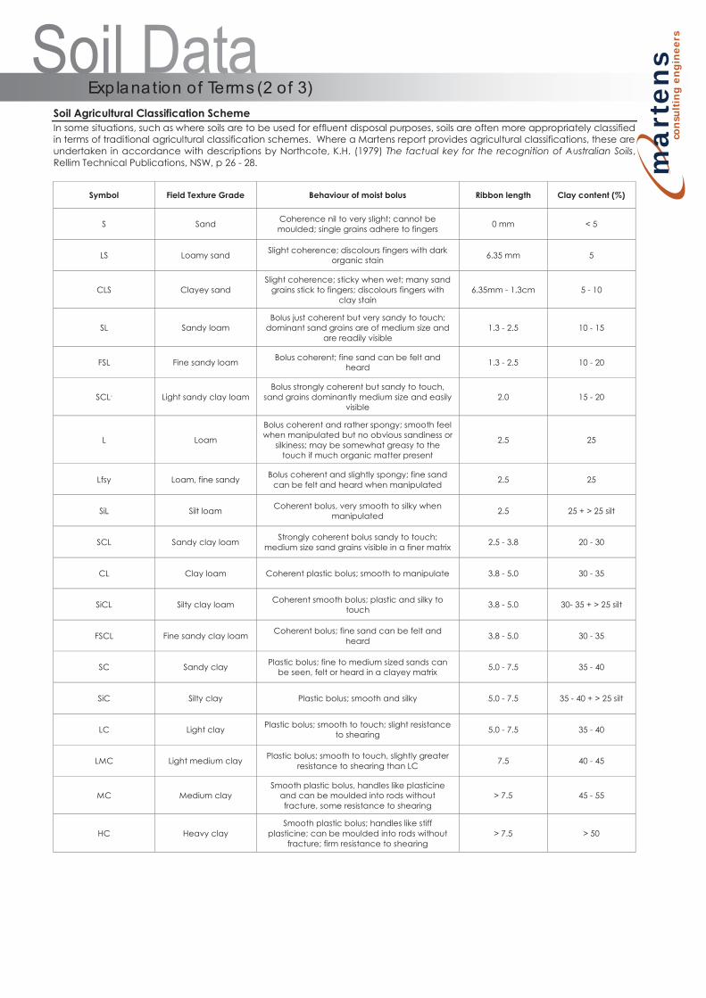
Soil Agricultural Classification Scheme In some situations, such as where soils are to be used for effluent disposal purposes, soils are often more appropriately classified in terms of traditional agricultural classification schemes. Where a Martens report provides agricultural classifications, these are undertaken in accordance with descriptions by Northcote, K.H. (1979) The factual key for the recognition of Australian Soils, Rellim Technical Publications, NSW, p 26 - 28.
Symbol Field Texture Grade Behaviour of moist bolus Ribbon length Clay content (%)
S Sand Coherence nil to very slight; cannot be moulded; single grains adhere to fingers 0 mm < 5
LS Loamy sand Slight coherence; discolours fingers with dark organic stain 6.35 mm 5
CLS Clayey sand Slight coherence; sticky when wet; many sand
grains stick to fingers; discolours fingers with clay stain
6.35mm - 1.3cm 5 - 10
SL Sandy loam Bolus just coherent but very sandy to touch;
dominant sand grains are of medium size and are readily visible
1.3 - 2.5 10 - 15
FSL Fine sandy loam Bolus coherent; fine sand can be felt and heard 1.3 - 2.5 10 - 20
SCL- Light sandy clay loam Bolus strongly coherent but sandy to touch,
sand grains dominantly medium size and easily visible
2.0 15 - 20
L Loam
Bolus coherent and rather spongy; smooth feel when manipulated but no obvious sandiness or
silkiness; may be somewhat greasy to the touch if much organic matter present
2.5 25
Lfsy Loam, fine sandy Bolus coherent and slightly spongy; fine sand can be felt and heard when manipulated 2.5 25
SiL Silt loam Coherent bolus, very smooth to silky when manipulated 2.5 25 + > 25 silt
SCL Sandy clay loam Strongly coherent bolus sandy to touch; medium size sand grains visible in a finer matrix 2.5 - 3.8 20 - 30
CL Clay loam Coherent plastic bolus; smooth to manipulate 3.8 - 5.0 30 - 35
SiCL Silty clay loam Coherent smooth bolus; plastic and silky to touch 3.8 - 5.0 30- 35 + > 25 silt
FSCL Fine sandy clay loam Coherent bolus; fine sand can be felt and heard 3.8 - 5.0 30 - 35
SC Sandy clay Plastic bolus; fine to medium sized sands can be seen, felt or heard in a clayey matrix 5.0 - 7.5 35 - 40
SiC Silty clay Plastic bolus; smooth and silky 5.0 - 7.5 35 - 40 + > 25 silt
LC Light clay Plastic bolus; smooth to touch; slight resistance to shearing 5.0 - 7.5 35 - 40
LMC Light medium clay Plastic bolus; smooth to touch, slightly greater resistance to shearing than LC 7.5 40 - 45
MC Medium clay Smooth plastic bolus, handles like plasticine
and can be moulded into rods without fracture, some resistance to shearing
> 7.5 45 - 55
HC Heavy clay Smooth plastic bolus; handles like stiff
plasticine; can be moulded into rods without fracture; firm resistance to shearing
> 7.5 > 50
Exp lana tion of Terms (2 of 3)
ma
rten
s
cons
ultin
g en
gine
ers
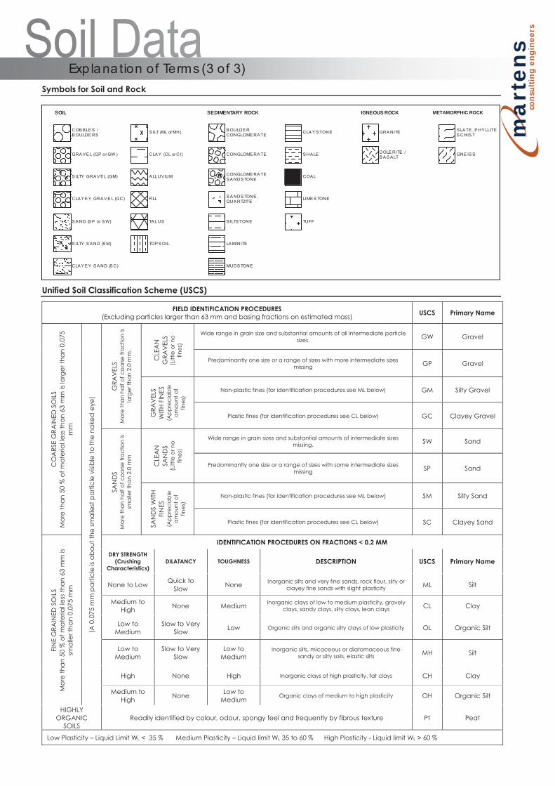
Symbols for Soil and Rock
Unified Soil Classification Scheme (USCS)
FIELD IDENTIFICATION PROCEDURES (Excluding particles larger than 63 mm and basing fractions on estimated mass) USCS Primary Name
CO
ARS
E G
RAIN
ED S
OIL
S M
ore
tha
n 50
% o
f ma
teria
l les
s tha
n 63
mm
is la
rger
tha
n 0.
075
mm
(A 0
.075
mm
pa
rticl
e is
ab
out t
he sm
alle
st p
arti
cle
visib
le to
the
nake
d e
ye)
GRA
VEL
S M
ore
than
hal
f of c
oarse
frac
tion
is la
rger
than
2.0
mm
.
CLE
AN
G
RAV
ELS
(Litt
le o
r no
fines
)
Wide range in grain size and substantial amounts of all intermediate particle sizes. GW Gravel
Predominantly one size or a range of sizes with more intermediate sizes missing GP Gravel
GRA
VEL
S W
ITH F
INES
(A
ppre
ciab
le
amou
nt o
f fin
es)
Non-plastic fines (for identification procedures see ML below) GM Silty Gravel
Plastic fines (for identification procedures see CL below) GC Clayey Gravel
SAN
DS
Mor
e th
an h
alf o
f coa
rse fr
actio
n is
smal
ler t
han
2.0
mm
CLE
AN
SA
ND
S (L
ittle
or n
o fin
es)
Wide range in grain sizes and substantial amounts of intermediate sizes missing. SW Sand
Predominantly one size or a range of sizes with some intermediate sizes missing SP Sand
SAN
DS
WITH
FI
NES
(A
ppre
ciab
le
amou
nt o
f fin
es)
Non-plastic fines (for identification procedures see ML below) SM Silty Sand
Plastic fines (for identification procedures see CL below) SC Clayey Sand
FIN
E G
RAIN
ED S
OIL
S M
ore
tha
n 50
% o
f ma
teria
l les
s tha
n 63
mm
is
sma
ller t
han
0.07
5 m
m
IDENTIFICATION PROCEDURES ON FRACTIONS < 0.2 MM
DRY STRENGTH (Crushing
Characteristics) DILATANCY TOUGHNESS
DESCRIPTION
USCS Primary Name
None to Low Quick to Slow None Inorganic silts and very fine sands, rock flour, silty or
clayey fine sands with slight plasticity ML Silt
Medium to High None Medium Inorganic clays of low to medium plasticity, gravely
clays, sandy clays, silty clays, lean clays CL Clay
Low to Medium
Slow to Very Slow Low Organic slits and organic silty clays of low plasticity OL Organic Silt
Low to Medium
Slow to Very Slow
Low to Medium
Inorganic silts, micaceous or diatomaceous fine sandy or silty soils, elastic silts MH Silt
High None High Inorganic clays of high plasticity, fat clays CH Clay
Medium to High None Low to
Medium Organic clays of medium to high plasticity OH Organic Silt
HIGHLY ORGANIC
SOILS Readily identified by colour, odour, spongy feel and frequently by fibrous texture Pt Peat
Low Plasticity – Liquid Limit WL < 35 % Medium Plasticity – Liquid limit WL 35 to 60 % High Plasticity - Liquid limit WL > 60 %
Exp lana tion of Terms (3 of 3)
SOIL
COB B LE S /B OULDE RS
GRA V E L (GP or GW )
S ILTY GRA V E L (GM)
CLA Y E Y GRA V E L (GC)
S A ND (S P or S W)
S ILTY S A ND (S M)
CLA Y E Y S A ND (S C)
S ILT (ML or MH)
CLA Y (CL or CI)
A LLUV IUM
FILL
TA LUS
TOP S OIL
SEDIMENTARY ROCK
B OULDE RCONGLOME RA TE
CONGLOME RA TE
CLA Y S TONE
CONGLOME RA TES A NDS TONE
S A NDS TONE ,QUA RTZITE
S HA LE
S ILTS TONE
LA MINITE
MUDS TONE
COA L
LIME S TONE
TUFF
IGNEOUS ROCK
GRA NITE
DOLE RITE /B A S A LT
IGNEOUS ROCK
S LA TE , P HY LLITES CHIS T
GNE IS S
METAMORPHIC ROCK
ma
rten
s
cons
ultin
g en
gine
ers
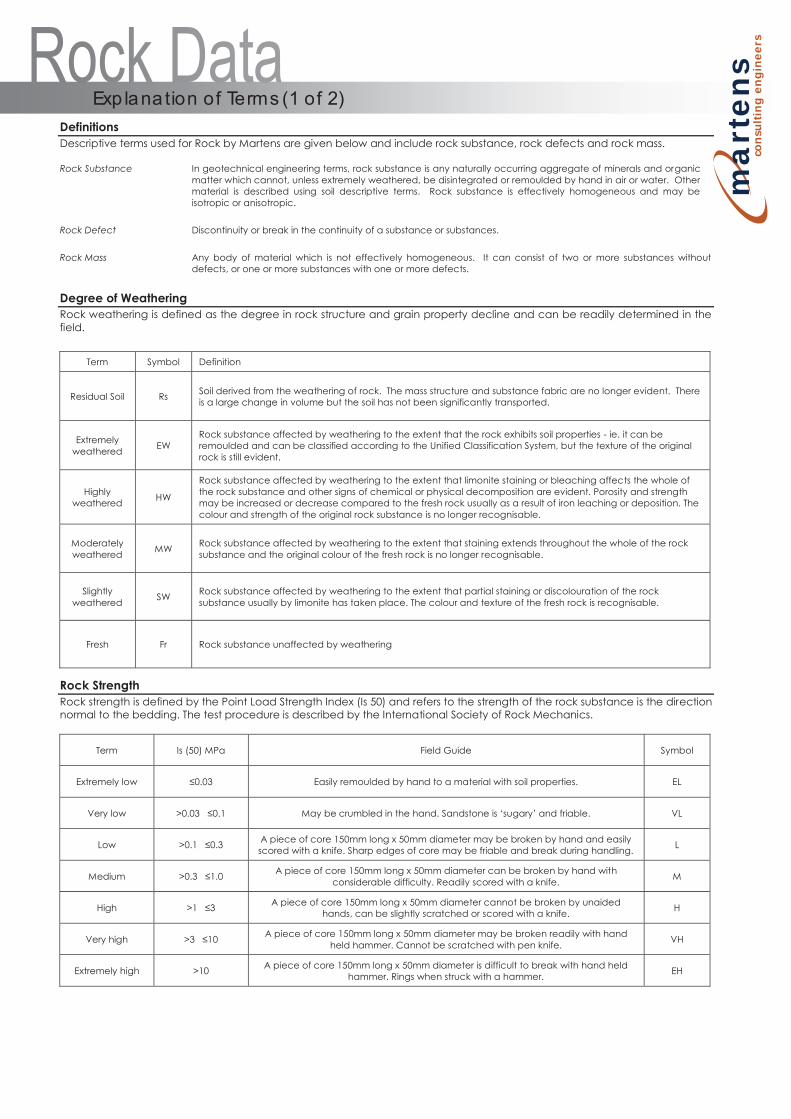
Definitions Descriptive terms used for Rock by Martens are given below and include rock substance, rock defects and rock mass. Rock Substance In geotechnical engineering terms, rock substance is any naturally occurring aggregate of minerals and organic
matter which cannot, unless extremely weathered, be disintegrated or remoulded by hand in air or water. Other material is described using soil descriptive terms. Rock substance is effectively homogeneous and may be isotropic or anisotropic.
Rock Defect Discontinuity or break in the continuity of a substance or substances.
Rock Mass Any body of material which is not effectively homogeneous. It can consist of two or more substances without defects, or one or more substances with one or more defects.
Degree of Weathering Rock weathering is defined as the degree in rock structure and grain property decline and can be readily determined in the field.
Term Symbol Definition
Residual Soil Rs Soil derived from the weathering of rock. The mass structure and substance fabric are no longer evident. There is a large change in volume but the soil has not been significantly transported.
Extremely weathered EW
Rock substance affected by weathering to the extent that the rock exhibits soil properties - ie. it can be remoulded and can be classified according to the Unified Classification System, but the texture of the original rock is still evident.
Highly weathered HW
Rock substance affected by weathering to the extent that limonite staining or bleaching affects the whole of the rock substance and other signs of chemical or physical decomposition are evident. Porosity and strength may be increased or decrease compared to the fresh rock usually as a result of iron leaching or deposition. The colour and strength of the original rock substance is no longer recognisable.
Moderately weathered MW Rock substance affected by weathering to the extent that staining extends throughout the whole of the rock
substance and the original colour of the fresh rock is no longer recognisable.
Slightly weathered SW Rock substance affected by weathering to the extent that partial staining or discolouration of the rock
substance usually by limonite has taken place. The colour and texture of the fresh rock is recognisable.
Fresh Fr Rock substance unaffected by weathering
Rock Strength Rock strength is defined by the Point Load Strength Index (Is 50) and refers to the strength of the rock substance is the direction normal to the bedding. The test procedure is described by the International Society of Rock Mechanics.
Term Is (50) MPa Field Guide Symbol
Extremely low ≤0.03 Easily remoulded by hand to a material with soil properties. EL
Very low >0.03 ≤0.1 May be crumbled in the hand. Sandstone is ‘sugary’ and friable. VL
Low >0.1 ≤0.3 A piece of core 150mm long x 50mm diameter may be broken by hand and easily scored with a knife. Sharp edges of core may be friable and break during handling. L
Medium >0.3 ≤1.0 A piece of core 150mm long x 50mm diameter can be broken by hand with considerable difficulty. Readily scored with a knife. M
High >1 ≤3 A piece of core 150mm long x 50mm diameter cannot be broken by unaided hands, can be slightly scratched or scored with a knife. H
Very high >3 ≤10 A piece of core 150mm long x 50mm diameter may be broken readily with hand held hammer. Cannot be scratched with pen knife. VH
Extremely high >10 A piece of core 150mm long x 50mm diameter is difficult to break with hand held hammer. Rings when struck with a hammer. EH
Exp lana tion of Terms (1 of 2)
ma
rten
s
cons
ultin
g en
gine
ers
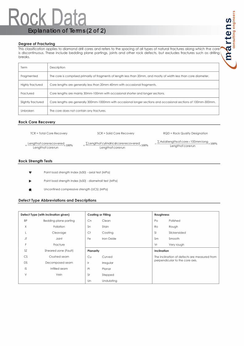
Degree of Fracturing This classification applies to diamond drill cores and refers to the spacing of all types of natural fractures along which the core is discontinuous. These include bedding plane partings, joints and other rock defects, but excludes fractures such as drilling breaks.
Term Description
Fragmented The core is comprised primarily of fragments of length less than 20mm, and mostly of width less than core diameter.
Highly fractured Core lengths are generally less than 20mm-40mm with occasional fragments.
Fractured Core lengths are mainly 30mm-100mm with occasional shorter and longer sections.
Slightly fractured Core lengths are generally 300mm-1000mm with occasional longer sections and occasional sections of 100mm-300mm.
Unbroken The core does not contain any fractures.
Rock Core Recovery
TCR = Total Core Recovery SCR = Solid Core Recovery RQD = Rock Quality Designation
%100run core of Length
recovered core of Length %100
run core of Lengthrecovered core lcylindrica of Length %100
run core of Lengthlong mm 100 core of lengths Axial
Rock Strength Tests
Point load strength Index (Is50) - axial test (MPa)
Point load strength Index (Is50) - diametrall test (MPa)
Unconfined compressive strength (UCS) (MPa)
Defect Type Abbreviations and Descriptions
Defect Type (with inclination given) Coating or Filling Roughness
BP
X
L
JT
F
SZ
CS
DS
IS
V
Bedding plane parting
Foliation
Cleavage
Joint
Fracture
Sheared zone (Fault)
Crushed seam
Decomposed seam
Infilled seam
Vein
Cn
Sn
Ct
Fe
Clean
Stain
Coating
Iron Oxide
Po
Ro
Sl
Sm
Vr
Polished
Rough
Slickensided
Smooth
Very rough
Planarity Inclination
Cu
Ir
Pl
St
Un
Curved
Irregular
Planar
Stepped
Undulating
The inclination of defects are measured from perpendicular to the core axis.
Exp lana tion of Terms (2 of 2) Exp lana tion of Terms (2 of 2) Exp lana tion of Terms (2 of 2) Exp lana tion of Terms (2 of 2)
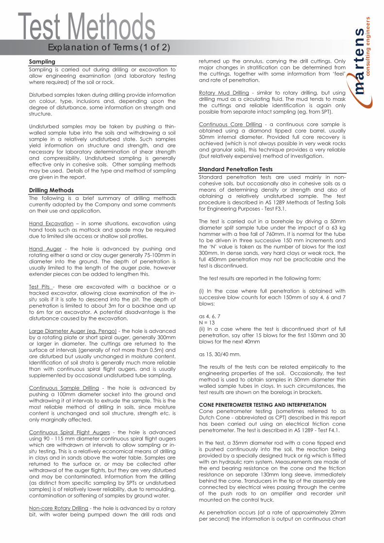
ma
rten
s
cons
ultin
g en
gine
ers
Sampling Sampling is carried out during drilling or excavation to allow engineering examination (and laboratory testing where required) of the soil or rock. Disturbed samples taken during drilling provide information on colour, type, inclusions and, depending upon the degree of disturbance, some information on strength and structure. Undisturbed samples may be taken by pushing a thin-walled sample tube into the soils and withdrawing a soil sample in a relatively undisturbed state. Such samples yield information on structure and strength, and are necessary for laboratory determination of shear strength and compressibility. Undisturbed sampling is generally effective only in cohesive soils. Other sampling methods may be used. Details of the type and method of sampling are given in the report. Drilling Methods The following is a brief summary of drilling methods currently adopted by the Company and some comments on their use and application. Hand Excavation – in some situations, excavation using hand tools such as mattock and spade may be required due to limited site access or shallow soil profiles. Hand Auger - the hole is advanced by pushing and rotating either a sand or clay auger generally 75-100mm in diameter into the ground. The depth of penetration is usually limited to the length of the auger pole, however extender pieces can be added to lengthen this. Test Pits - these are excavated with a backhoe or a tracked excavator, allowing close examination of the in-situ soils if it is safe to descend into the pit. The depth of penetration is limited to about 3m for a backhoe and up to 6m for an excavator. A potential disadvantage is the disturbance caused by the excavation. Large Diameter Auger (eg. Pengo) - the hole is advanced by a rotating plate or short spiral auger, generally 300mm or larger in diameter. The cuttings are returned to the surface at intervals (generally of not more than 0.5m) and are disturbed but usually unchanged in moisture content. Identification of soil strata is generally much more reliable than with continuous spiral flight augers, and is usually supplemented by occasional undisturbed tube sampling. Continuous Sample Drilling - the hole is advanced by pushing a 100mm diameter socket into the ground and withdrawing it at intervals to extrude the sample. This is the most reliable method of drilling in soils, since moisture content is unchanged and soil structure, strength etc. is only marginally affected. Continuous Spiral Flight Augers - the hole is advanced using 90 - 115 mm diameter continuous spiral flight augers which are withdrawn at intervals to allow sampling or in-situ testing. This is a relatively economical means of drilling in clays and in sands above the water table. Samples are returned to the surface or, or may be collected after withdrawal of the auger flights, but they are very disturbed and may be contaminated. Information from the drilling (as distinct from specific sampling by SPTs or undisturbed samples) is of relatively lower reliability, due to remoulding, contamination or softening of samples by ground water. Non-core Rotary Drilling - the hole is advanced by a rotary bit, with water being pumped down the drill rods and
returned up the annulus, carrying the drill cuttings. Only major changes in stratification can be determined from the cuttings, together with some information from ‘feel’ and rate of penetration. Rotary Mud Drilling - similar to rotary drilling, but using drilling mud as a circulating fluid. The mud tends to mask the cuttings and reliable identification is again only possible from separate intact sampling (eg. from SPT). Continuous Core Drilling - a continuous core sample is obtained using a diamond tipped core barrel, usually 50mm internal diameter. Provided full core recovery is achieved (which is not always possible in very weak rocks and granular soils), this technique provides a very reliable (but relatively expensive) method of investigation. Standard Penetration Tests Standard penetration tests are used mainly in non-cohesive soils, but occasionally also in cohesive soils as a means of determining density or strength and also of obtaining a relatively undisturbed sample. The test procedure is described in AS 1289 Methods of Testing Soils for Engineering Purposes - Test F3.1. The test is carried out in a borehole by driving a 50mm diameter split sample tube under the impact of a 63 kg hammer with a free fall of 760mm. It is normal for the tube to be driven in three successive 150 mm increments and the ‘N’ value is taken as the number of blows for the last 300mm. In dense sands, very hard clays or weak rock, the full 450mm penetration may not be practicable and the test is discontinued. The test results are reported in the following form: (i) In the case where full penetration is obtained with successive blow counts for each 150mm of say 4, 6 and 7 blows: as 4, 6, 7 N = 13 (ii) In a case where the test is discontinued short of full penetration, say after 15 blows for the first 150mm and 30 blows for the next 40mm as 15, 30/40 mm. The results of the tests can be related empirically to the engineering properties of the soil. Occasionally, the test method is used to obtain samples in 50mm diameter thin walled sample tubes in clays. In such circumstances, the test results are shown on the borelogs in brackets. CONE PENETROMETER TESTING AND INTERPRETATION Cone penetrometer testing (sometimes referred to as Dutch Cone - abbreviated as CPT) described in this report has been carried out using an electrical friction cone penetrometer. The test is described in AS 1289 - Test F4.1. In the test, a 35mm diameter rod with a cone tipped end is pushed continuously into the soil, the reaction being provided by a specially designed truck or rig which is fitted with an hydraulic ram system. Measurements are made of the end bearing resistance on the cone and the friction resistance on separate 130mm long sleeve, immediately behind the cone. Tranducers in the tip of the assembly are connected by electrical wires passing through the centre of the push rods to an amplifier and recorder unit mounted on the control truck. As penetration occurs (at a rate of approximately 20mm per second) the information is output on continuous chart
Exp lana tion of Terms (1 of 2)
ma
rten
s
cons
ultin
g en
gine
ers
recorders. The plotted results given in this report have been traced from the original records. The information provided on the charts comprises: Cone resistance - the actual end bearing force divided by the cross sectional area of the cone - expressed in MPA. Sleeve friction - the frictional force of the sleeve divided by the surface area - expressed in kPa. Friction ratio - the ratio of sleeve friction to cone resistance - expressed in percent. There are two scales available for measurement of cone resistance. The lower (A) scale (0 - 5 Mpa) is used in very soft soils where increased sensitivity is required and is shown in the graphs as a dotted line. The main (B) scale (0 - 50 Mpa) is less sensitive and is shown as a full line. The ratios of the sleeve resistance to cone resistance will vary with the type of soil encountered, with higher relative friction in clays than in sands. Friction ratios of 1%-2% are commonly encountered in sands and very soft clays rising to 4%-10% in stiff clays. In sands, the relationship between cone resistance and SPT value is commonly in the range: qc (Mpa) = (0.4 to 0.6) N (blows/300mm) In clays, the relationship between undrained shear strength and cone resistance is commonly in the range: qc = (12 to 18) cu Interpretation of CPT values can also be made to allow estimation of modulus or compressibility values to allow calculation of foundation settlements. Inferred stratification as shown on the attached reports is assessed from the cone and friction traces and from experience and information from nearby boreholes etc. This information is presented for general guidance, but must be regarded as being to some extent interpretive. The test method provides a continuous profile of engineering properties, and where precise information on soil classification is required, direct drilling and sampling may be preferable. DYNAMIC CONE (HAND) PENETROMETERS Hand penetrometer tests are carried out by driving a rod into the ground with a falling weight hammer and measuring the blows for successive 150mm increments of penetration. Normally, there is a depth limitation of 1.2m but this may be extended in certain conditions by the use of extension rods. Two relatively similar tests are used. Perth sand penetrometer - a 16 mm diameter flat ended rod is driven with a 9kg hammer, dropping 600mm (AS 1289 - Test F 3.3). This test was developed for testing the density of sands (originating in Perth) and is mainly used in granular soils and filling. Cone penetrometer (sometimes known as the Scala Penetrometer) - a 16mm rod with a 20mm diameter cone end is driven with a 9kg hammer dropping 510mm (AS 1289 - Test F 3.2). The test was developed initially for pavement sub-grade investigations, with correlations of the test results with California bearing ratio published by various Road Authorities. LABORATORY TESTING Laboratory testing is carried out in accordance with AS 1289 Methods of Testing Soil for Engineering Purposes. Details of the test procedure used are given on the individual report forms.
TEST PIT / BORE LOGS The test pit / bore log(s) presented herein are an engineering and/or geological interpretation of the sub-surface conditions and their reliability will depend to some extent on frequency of sampling and the method of excavation / drilling. Ideally, continuous undisturbed sampling or excavation / core drilling will provide the most reliable assessment, but this is not always practicable, or possible to justify on economic grounds. In any case, the boreholes represent only a very small sample of the total subsurface profile. Interpretation of the information and its application to design and construction should therefore take into account the spacing of boreholes, the frequency of sampling and the possibility of other than ‘straight line’ variation between the boreholes. GROUND WATER Where ground water levels are measured in boreholes, there are several potential problems: In low permeability soils, ground water although present, may enter the hole slowly, or perhaps not at all during the time it is left open. A localised perched water table may lead to an erroneous indication of the true water table. Water table levels will vary from time to time with seasons or recent prior weather changes. They may not be the same at the time of construction as are indicated in the report. The use of water or mud as a drilling fluid will mask any ground water inflow. Water has to be blown out of the hole and drilling mud must first be washed out of the hole if water observations are to be made. More reliable measurements can be made by installing standpipes which are read at intervals over several days, or perhaps weeks for low permeability soils. Piezometers sealed in a particular stratum, may be advisable in low permeability soils or where there may be interference from a perched water table.
Exp lana tion of Terms (2 of 2)