Embed Size (px)
Citation preview
1
CHAPTER-1
INTRODUCTION
1.1 OVERVIEW OF FREQUENCY SELECTIVE SURFACE
The frequency selective surface (FSS) structure is an array of periodically arranged
metallic patches on a dielectric substrate or slots in the metallic screen, which behaves
as a spatial filter to the electromagnetic waves and offer selectivity in frequency,
angle-of-incidence (AOI) and polarization of the incident waves [1]. The FSS can be
classified as high-pass, low-pass, bandpass and bandstop filter. These features make
them suitable to control the propagation of electromagnetic energy and therefore, they
can be employed in radomes, Cassegrain sub-reflector, diffraction gratings, frequency
scanned antennas, microwave absorbers and recently in applications associated with
security and efficiency of the wireless network communications [1-11]. As, Sinclair
[12] has realized that the antennas placed on the aircraft provide significant scatterers,
however, it is required to control the radar cross-section (RCS) of the antenna, which
is significantly accomplished to an extent by using the FSS structure [13]. The basic
principle underlying the physics of FSS structure is directly been evolved from the
investigation of diffraction gratings in optics, which is used to decompose a beam of
non-monochromatic light into its spectral orders. However, the study of FSS
structures and their interaction with electromagnetic waves received potential
attention in the mid-1960s. In addition to this, there are many literatures, which had
been reported from 1919 to the famous Marconi and Franklin reflector for use in
wireless telegraphy and telephony [1]. The patch- and slot-type FSS structures ideally
exhibit total reflection and transmission, respectively, in the neighbourhood of the
fundamental resonance frequency. The type of element geometry, size, inter-element
spacing, dielectric substrate parameters and presence or absence of superstrate, which
constitutes the unit-cell element, determines the overall resonance frequency,
bandwidth and dependency on the AOI as well as polarization of the planar incoming
wave. Therefore, in order to design a FSS structure for a desired frequency response,
the appropriate selection of geometrical parameters is of prime importance because
these parameters have potential to significantly vary the frequency response. The

2
unique characteristics and practical significances of FSS structures realized over many
years have offered an extensive work both in academia and industrial sectors.
(a)
(b)
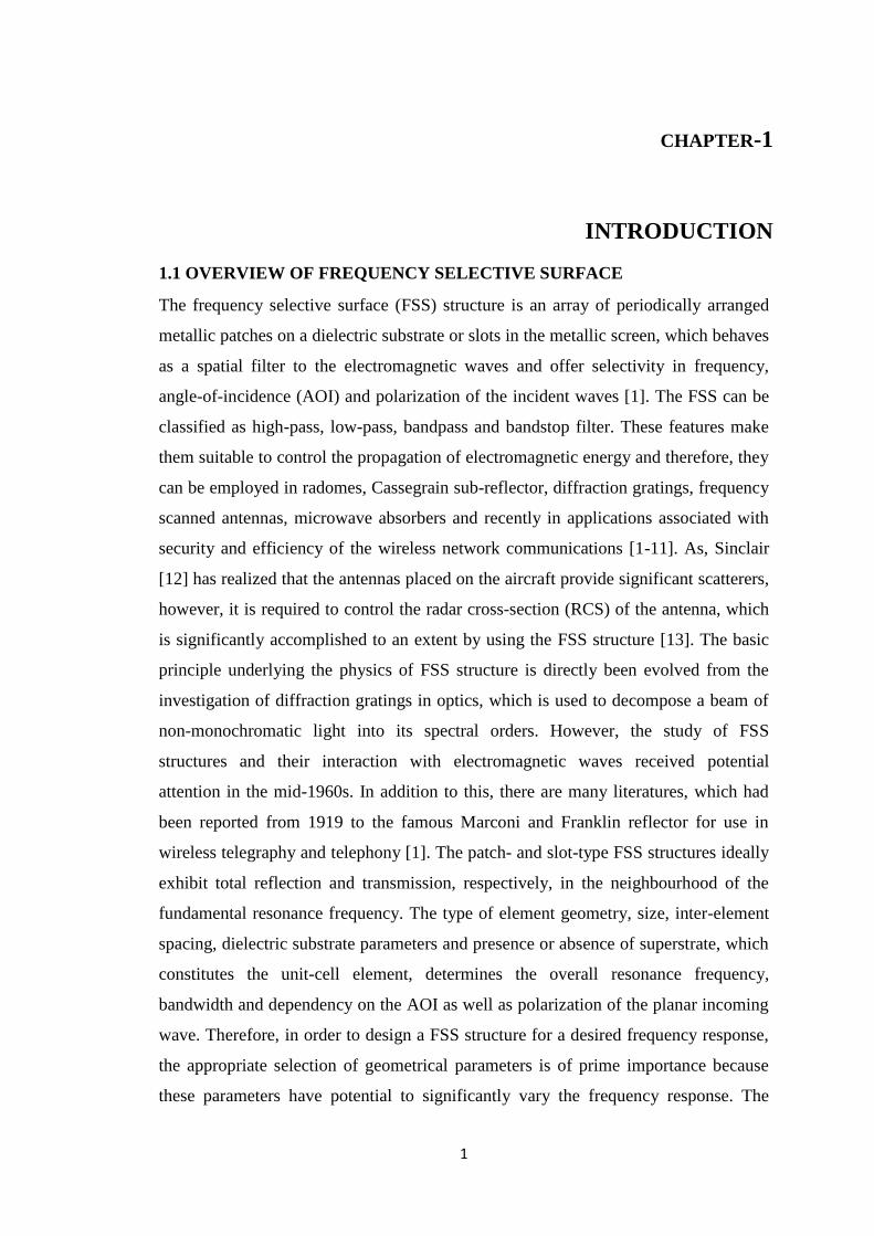
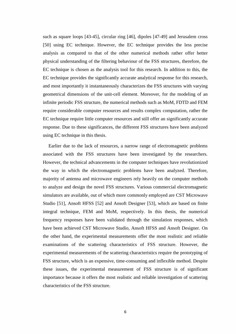
Fig.1.1 The basic filtering mechanism of FSS structure for E-vector (a) parallel and (b)
orthogonal to the metallic dipole [14].
In order to understand the physical mechanism of the FSS filtering characteristics,
two scenarios of the plane wave incidence on a metallic dipole FSS structure is
presented as shown in Fig. 1.1. In the first scenario, a plane wave impinges on a
metallic dipole FSS structure in such a way that the FSS structure is orthogonal to the
Poynting vector and electric field vector is oriented along the length of the dipole as
shown in Fig. 1.1(a) [14]. The electric field vector oscillates the electrons due to
which a portion of incidence plane wave energy is transformed into kinetic energy
and gives rise to re-radiated waves/energy. These re-radiated waves on the right side
of the FSS structure results in the cancellation of the incidence plane wave, which are
3
on the left side of the FSS structure. In addition to this, the re-radiated waves on the
left side of the FSS structure refer to as the reflected wave and this scenario result the
low transmittance through the FSS filter [15]. In the second scenario, the electric field
vector is orthogonal to the parallel metallic dipole FSS, which is shown in Fig. 1.1(b)
[14]. In this case, the electrons do not re-radiate because of their inability to oscillate
up and down. Therefore, the FSS structure remains invisible to the incidence plane
wave and total transmission occurs or transmittance will be higher [15].
1.2 NUMERICAL TECHNIQUES FOR ANALYSIS OF FSS
In the computation of electromagnetic fields scattered by the FSS, several numerical
methods are used. Various researchers have analyzed the reflection and transmission
characteristics of different FSS structures through numerical techniques and validated
the results through experimental measurements. However, all the numerical
techniques are based on the well established Maxwell‟s equations and in general,
these techniques are unable to provide exact solutions of the electromagnetic problem
rather offer approximate solutions of sufficient accuracy. In the last five decades,
various numerical techniques such as plane wave expansion method [16], spectral-
domain Galerkin method [17, 18], method-of-moment (MoM) [19], finite methods
(finite-difference-time-domain (FDTD) method [20, 21]/finite-element method (FEM)
[22]) and equivalent circuit (EC) [23] method have been discussed to investigate the
scattering characteristics of different FSS structures. Among the above mentioned
numerical techniques, MoM, FDTD, FEM and EC technique are the most widely used
numerical techniques. However, the MoM, FDTD and FEM are the computational
intensive techniques and EC technique is comparatively simpler one. The selection of
optimal technique for numerical modeling of FSS structure remains open. In this
Section, we have discussed the state-of-the-art of different numerical techniques,
which are available for the simulation of electromagnetic problems associated with
the FSS structures.
The MoM technique investigated the scattering characteristics of the FSS structure
in the frequency domain. The numerical modeling of FSS structure using MoM is
initially discussed by Chen [24], which evaluates the current flowing on the metallic
pattern by matching the tangential field at the surface of the unit-cell element and
forms the integral equation for the unknown current. Further, the unknown electric
4
field depends upon the unknown current near the metallic pattern, which is expanded
into a set of Floquet modes and by satisfying the boundary conditions on the surface
of the metallic pattern, an integral equation for the unknown current is obtained. At
the final stage, the MoM is used to reduce the integral equation into a set of linear
algebraic equations. Earlier, the approach discussed by Chen [24], is referred as the
integral equation approach. The generalized steps to solve the scattering problem
using MoM method are:
1) Expand the unknown function in terms of a set of N basis function with
unknown coefficient,
2) Enforce boundary conditions of the problems to generate a linear system of N
equations, and
3) Solve the linear system of equations for unknown coefficients.
Thereafter, various researchers have discussed the different advancements in the
MoM method to reduce its computational complexity [25-29]. The MoM approach
has the potential to evaluate the scattering characteristics over a wide range of AOIs,
however it is usually restricted up to periodic FSS structures, which have supported
homogeneous dielectric substrate.
In order to investigate the complex FSS structure, which are backed with
inhomogeneous dielectric substrate, the FDTD and FEM approach comes out to be an
effective numerical tool [30]. These two methods come under the category of finite
methods.
The FDTD technique investigates the scattering characteristics of FSS structure in
time domain and covers a wide frequency range in a single simulation run. This
technique is a direct solution of Maxwell's time dependent curl equations [31]. The
steps to solve the scattering problem using FDTD are:
1) Breakdown the solution region into grid of nodes such as dividing the solution
region into two different grids of nodes, one for the calculation of magnetic
field and the other for the calculation of electric field,
2) Approximating the given differential equation by finite difference equivalent
that relates the dependent variable at a point in the solution region to its values
5
at neighbouring point such as the value of magnetic field at an instant is
calculated by the electric field at previous grid points, in other words, the
electric field is solved at a given instant in time, then the magnetic field is
solved at the next instant in time and so on [32], and
3) Solving the difference equations subjected to the prescribed boundary/initial
conditions [33, 34]. In addition to this, various other scientists have discussed
the numerical modeling of different FSS structures using the FDTD as discussed
in [35-37].
The FEM technique investigates the scattering characteristics of different FSS
structures in frequency domain and initialize with the partial differential equation
form of Maxwell‟s equation. The generalized steps for the scattering problem using
FEM technique are:
1) Discretize the solution region into finite number of sub regions and corner of
each sub-region is called as node. In the first step, this method determine the
field quantities at these nodes,
2) Derive governing equations for a typical sub region,
3) Integrating all sub-regions over the entire geometry, and
4) Solving the system of equations obtained from above steps.
The technical advancements in the FEM are discussed by various researchers as
discussed in [38-40].
In comparison to the aforementioned numerical techniques, which are
computationally intensive, the EC technique provides a simpler method to investigate
the scattering characteristics of the different FSS structures. The EC technique is
based on the transmission line analogy, where the EC parameters of a FSS structure is
obtained due to the inductive and capacitive behavior of its geometrical parameters as
discussed by Marcuvitz [41, 42]. This technique is a scalar technique due to which the
modeling is limited upto linear polarizations and simple FSS geometries only.
However, the dielectric substrates parameters and AOIs have been taken into account
in the EC equations and the accuracy of the technique depends upon the assumptions
made in the analysis. Various researchers have analyzed the different FSS structures
6
such as square loops [43-45], circular ring [46], dipoles [47-49] and Jerusalem cross
[50] using EC technique. However, the EC technique provides the less precise
analysis as compared to that of the other numerical methods rather offer better
physical understanding of the filtering behaviour of the FSS structures, therefore, the
EC technique is chosen as the analysis tool for this research. In addition to this, the
EC technique provides the significantly accurate analytical response for this research,
and most importantly it instantaneously characterizes the FSS structures with varying
geometrical dimensions of the unit-cell element. Moreover, for the modeling of an
infinite periodic FSS structure, the numerical methods such as MoM, FDTD and FEM
require considerable computer resources and results complex computation, rather the
EC technique require little computer resources and still offer an significantly accurate
response. Due to these significances, the different FSS structures have been analyzed
using EC technique in this thesis.
Earlier due to the lack of resources, a narrow range of electromagnetic problems
associated with the FSS structures have been investigated by the researchers.
However, the technical advancements in the computer techniques have revolutionized
the way in which the electromagnetic problems have been analyzed. Therefore,
majority of antenna and microwave engineers rely heavily on the computer methods
to analyze and design the novel FSS structures. Various commercial electromagnetic
simulators are available, out of which more commonly employed are CST Microwave
Studio [51], Ansoft HFSS [52] and Ansoft Designer [53], which are based on finite
integral technique, FEM and MoM, respectively. In this thesis, the numerical
frequency responses have been validated through the simulation responses, which
have been achieved CST Microwave Studio, Ansoft HFSS and Ansoft Designer. On
the other hand, the experimental measurements offer the most realistic and reliable
examinations of the scattering characteristics of FSS structure. However, the
experimental measurements of the scattering characteristics require the prototyping of
FSS structure, which is an expensive, time-consuming and inflexible method. Despite
these issues, the experimental measurement of FSS structure is of significant
importance because it offers the most realistic and reliable investigation of scattering
characteristics of the FSS structure.
7
1.3 RELATED WORK
The FSS structures offer various applications in microwave, optical wave and
terahertz regime of the electromagnetic spectrum [54-62]. The FSS structure is used
to mitigate the interference, improve the gain/directivity of an antenna, and design the
radome in the microwave regime of the electromagnetic spectrum. In addition to this,
these structures provide potential applications in the satellite communication where it
is required to maintain the purity of the signal in the specific band and to control the
scattering characteristics of the signal to the desired level [63, 64]. The FSS structures
have been used as polarizer, beam splitter and solar-energy collector in the optical
wave regime and offer applications in imaging, sensing and communication in the
terahertz regime of electromagnetic spectrum [65, 66]. However, for the significant
functioning of FSS structures in microwave applications, these structures must
provide a frequency response, which is close to the ideal filter‟s frequency response
and must be stable to the wide range of AOIs and different polarizations of the
incidence wave. However, the complete knowledge of reflection and transmission
characteristics at the periodic array face is very essential to achieve the
aforementioned frequency characteristics. Therefore, in this section, we have
discussed the circuit parameter characterization to achieve the desired frequency
response and the effect of AOIs/polarization of the incoming wave on the frequency
response of FSS structure. Further, in the context of aforementioned performance
requirements, the following sub-sections discuss the frequency characteristics of two
dimensional FSS structure for single and multiband frequency characteristics through
number of design examples.
1.3.1 CIRCUIT PARAMETER CHARACTERIZATION
There are various well established numerical techniques as discussed in Section 1.2 to
analyze the different FSS structures. In this sub-section, we have discussed recent
advanced numerical methods, which have been used for the analysis of different FSS
structures. Kristensson et al in [67] have discussed the dielectric (bianisotropic
material) backed FSS structure using the improved MoM, which also provide the
integral representation of electromagnetic fields outside the dielectric slab. The MoM
is used to obtain the unknown current on the FSS and from this current quantity, other
parameters have been calculated. However, to design the FSS structure, the relevant
8
parameter selection process depends on the trial-error method and nature-inspired
population based methods such as the genetic algorithm (GA) and particle swarm
optimization (PSO), which demands the pattern of periodic structure and the
parameters of the fixed pattern, need to be determined. In this view, Li et al [68] have
integrated GA, used for optimization with fast full-wave numerical methods. In [69],
the PSO has been used to adjust the geometrical parameters such as element size and
spacing of the square loop FSS structure for the desired features and further the EC
technique has been used for the analysis. For implementing PSO, first revisit the
derivation of the EC formulation and then an objective function, which is based on the
transmission coefficients at various frequencies at the pass/stop-bands, is defined. In
PSO, instead of using a totally-chance oriented trial-error method, a multi-
dimensional search operation is performed systematically by means of swarm
intelligence. Dubrovka et al [70] have proposed a new general EC approach for a thin
FSS, which is valid for any AOI and for any lattices, known as modal decomposition
EC model (MDECM). This method is based on determining the admittances that
relate the voltage and current intensity amplitudes for any incident Floquet mode and
is achieved by studying the interaction of the plane waves of arbitrary AOI with the
structure. Since, the general formulation of the method is very complex, so an
approximate (testing) function for the aperture field is used to produce relatively
simple circuits that can approximate the true admittance of the frequency selective
surface and accuracy of the procedure depends upon the choice of the testing function.
In order to validate the method, a theoretical study of the method has been considered
using the ring slot and rectangular slot elements as test elements and the results of
theoretical analysis are comparable with the computational electromagnetics (CEM)
simulation. This method exhibits higher accuracy compared with conventional EC
approaches and provides a better understanding of operation of FSS and potentially
allows the synthesis by optimization of the circuit parameters, however, this method
becomes rigorous for the highly complex structures such as Jerusalem cross. Sung et
al [71] have implemented FSS-wall, which filter out undesired interference and
accordingly improve the wireless system performance. Moreover, the scattering
performance of FSS-wall is investigated using the EC modelling, which provides the
comparable frequency response with the measured results. A dielectric backed FSS

9
structure, which provides compact (half of the original size) spatial band-pass filtering
characteristics, is designed using GA and analyzed using the EC approach [72].
However, the designing approach discussed in [72] is only valid for normal wave
incidences. In [73], a novel EC model using the GA is proposed to optimize the
square loop FSS parameters for the desired transmission/reflection response
effectively. The fitness function of GA is defined with the help of the EC model and a
significantly short simulation time is achieved as compared to that of the GA without
EC model. Various researchers have discussed different other novel numerical
techniques such as Su et al [74] have analyzed the arbitrary shape patch/aperture FSS
array using spectral domain integral equation method with Ewald transformation,
which accelerates the computation. In order to further reduce the computation time,
the lattice symmetry is introduced which reduce the number of unknown functions
and linear equations [74]. The scale changing technique and finite element technique
is compared for the analysis of finite size and thick FSS and reveals that the
computation time in the scale changing technique significantly very less as compared
to that of the FEM [75].
1.3.2 ANGULAR STABILITY
However, the resonance frequency of the FSS structure depends on the AOIs and
polarization states of the incidence wave [76, 77] and there are various ways to reduce
its dependency such as through the reactive loading of the dipoles, which is discussed
in [78]. In [79], Xu et al have demonstrated angular insensitivity and narrow band
transmission using capacitive loaded ring slot FSS structure, which is miniaturized to
0.082λ. The FSS structure discussed in [79] is placed in a Faraday cage structure
created by a row of metallic substrate to eliminate the undesired coupling between the
unit-cells. In order to improve the frequency response of the FSS structures in terms
of the angular sensitivity, cross-polarization, reflection/transmission bandwidth and
band-separation, several researchers have investigated the loaded (active/tunable,
passive) FSS structures [80-83]. In addition to this, in [84], an active loaded FSS has
been designed using PIN diodes between the FSS elements as well as DC magnetic
biasing has been performed with ferrite substrate to ensure the loading effect, which
tune the resonant frequency over a wide range and also switch the frequency response.
In [85], the loading has been achieved through the varactor diodes which act as
10
capacitive loading in the ring and makes the FSS structure tunable. Mias [86] has
been achieved loading through the surface mount reactive lumped element, which
shifts the bandstop frequency from higher to lower value and vice-versa. However,
these types of the structures are difficult to fabricate because of the complexity and
cost of fabrication. In [87], the passively loaded slot elements have been discussed to
achieve the dual band FSS structures, which significantly improve the bandwidth. In
[88], a short-length (less than λ/2) loaded dipole FSS array, which provide unity
reflection/transmission coefficient over a narrow bandwidth and is nearly independent
up to 65o
AOI at desired frequency is achieved. The angular independence is achieved
because the mutual impedance of short-length loaded dipole is less than the self
impedance, which reduces the coupling effect between the scattering elements. Shaker
and Shafai [89] have discussed the angular sensitivity of square patch elements
surrounded by square short or open circuited conducting square rings. The angular
sensitivity of the open and short square ring without the central square patch is
discussed and demonstrated that the open ring is more angular stable [89]. In addition
to this, loading of open and short square ring with the square patch further improves
the angular stability. It is also been demonstrated that due to the asymmetrical
geometry, the single layered open circuited square ring loaded with central square
patch is not suitable for dual/circular polarization [89]. On the other hand, the short
circuited square ring provides higher angular sensitivity while placed on a single layer
substrate [89]. Further, a double-layer shorted ring FSS array, which provide an
angular stable FSS structure for the certain separation of the dielectric layer is
discussed [90]. Ghaffer et al [91] have discussed the angular stability of square loop
FSS structure loaded with four PIN diodes across the aperture at 90o intervals up to
45o AOIs. Another tunable circular ring, split ring and convoluted ring FSS
structures loaded with varactor diodes and surface mount resistors, which provide
independent tuning for vertical and horizontal polarizations is discussed [92].
As discussed in section 1.2, there are various numerical techniques, which are
discussed in reported literature however the synthesis technique, which is used to
obtain the geometrical parameters of the FSS structure is also of significant
importance. In view of this, we have discussed a generalized synthesis technique of
single square loop FSS (SSLFSS), which provide the potential to meet the specific

11
resonance and bandwidth requirements. With the consideration of the angular and
polarization stability taken into account, in this thesis, the novel FSS structures have
been discussed, which are simple and provide significant angular and polarization
stability.
1.3.3 MULTIBAND PERFORMANCE
Various researchers have discussed the different ways of achieving multiband
characteristics in FSS structures, which accomplish these structures as the highly
effective communication devices. However, to fulfil the increasing demand of
multifunctional antennas/filters for the advanced communication systems, for
example, the multi-functional sub-reflectors for satellite communication, there is need
to develop multiband FSS structures [93-104]. FSS structures have widely used as
sub-reflectors for the satellite communication in which a single main reflector share
the different frequency bands and to increase the capabilities of multifunction and
multi-frequency antennas, a subreflector equipped with FSS structure is required to
operate at multi-frequency bands. In order to achieve the multiband frequency
response, there are various available approaches such as layered/stacked FSS [105,
106], fractal/convoluted FSS [107-111], perturbation of a single-layered FSS [112],
multi-resonant element FSS [113-116], and combination of these approaches [117,
118]. Initially, the layered/stacked FSS structures have been employed to provide the
multiband frequency characteristics, which offer significant frequency response over a
wide range of AOIs and different polarizations of the incidence wave. However these
structures are complex, heavier, larger in volume and expensive, which are not
suitable from practical perspectives [105, 106]. Further, the fractal/convoluted FSS
structures have been explored, however these require high degree of iterations and are
difficult to manufacture [107-111]. However, Werner and Lee [109] have discussed
the three- stage design methodology to obtain the fractal crossbar tree based FSS
structure, which provides the dual polarized (TE and TM) tri-band frequency response
and may have further extended to achieve the multi-band frequency response. Ohira et
al [110] have designed a single layer fractal FSS structure using micro-GA, which
offer significant close reflection band separation and bandwidth as compared to that
of the convoluted double square loop FSS structure. Further, Chiu and Wang [111]
have presented a FSS structure with four symmetrical patterns of metallic meander

12
lines with a central patch, which is printed on only one surface of a substrate for the
different polarization states and up to 60o AOIs. The FSS structure discussed in [111]
provides a dual-band frequency response, closely spaced bands of operation,
miniaturization of ~ 8% of the free-space wavelength at the first resonance frequency
and ~ 1.4 band separation. Hill and Munk [112] have designed a single layer dual-
band FSS using the perturbation technique, whose frequency response is sensitive to
different polarization states of the incidence wave. However, for the satellite
communication applications, a simplified design, low profile, lighter in weight FSS
structure is the prime demand, which is satisfied using the FSS structure with multi-
resonant elements [113-116]. Parker et al [113] have discussed the concentric ring
FSS, which is largely sensitive to the AOIs. Huang et al [114] have discussed a dual-
layer (single and double screen) circular ring FSS structure has been discussed, which
reflects X-band frequencies as well as transmits the S-band/Ku-band frequencies and
results in a complex tri-band FSS structure. It has also been demonstrated that the
double-screen panel of this FSS design that is backed with high dielectric constant
material provides the lower transmission loss at S-band and wider reflection
bandwidth at X-band than the single-screen panel [114]. Wu [115] has discussed a
multiband (reflect Ka-band signal and transmit S-band/X-band/Ku-band signals)
double square loop FSS with two dielectric layers, which are separated by a honey-
comb and provides a complex FSS structure. Wu and Lee [116] have discussed a
three layer FSS with circular concentric non-symmetric rings, which provide the
similar frequency response as discussed in 115]. On the other hand, Delihacioglu et al
[119] have discussed the angular and polarization behavior of dielectric backed L-
shaped and one-turn helix shape FSS structure up to 60o and 45
o, respectively for the
perpendicular and parallel polarized wave using modal expansion method. The
numerical frequency response of the FSS structure is comparable as compared to that
of the measured frequency response. In [120], the scattering characteristics
(reflection/transmission) of bandstop triangular FSS structure for the perpendicular
and parallel polarized wave incidence up to 45o are discussed. In addition to this, the
results demonstrated in [120] reveal that the equilateral triangular conducting element/
isosceles triangular conducting elements exhibit same filtering properties as compared
to that of the reported FSS structures.
13
With the consideration of aforementioned issues into account and to achieve
simplified, low profile, lighter weight and spectral efficient multiband FSS in terms of
angular and polarization (horizontal and vertical), we have proposed single layer
novel multi-resonant FSS structure, which provide the bandstop and bandpass
filtering characteristics as discussed in Chapter-5.
1.4 FACTORS AFFECTING THE FSS FREQUENCY RESPONSE
There are various factors, which govern the performance of the FSS structures, out of
which the critical factors are:
A) Shape and parameters of element,
B) Dielectric substrate parameters,
C) AOIs and polarizations of the incidence wave, and
D) Element conductivity
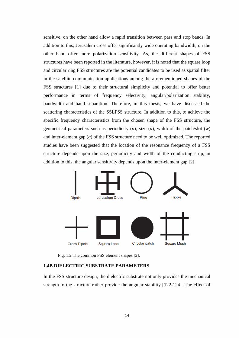
1.4A SHAPE AND PARAMETER OF THE ELEMENT
The shape of FSS element has the potential of providing the desired frequency
characteristics [121]. The FSS structure is composed of a metallic pattern, which is
placed on a dielectric substrate and the choice of the metallic pattern depends upon
the type of the application to which it has been used. The shape of the metallic pattern
is unconstrained, however Munk [2], has categorized the shape of the metallic pattern
of the FSS structures into four basic sections such as:
1) Centre connected or N-pole type: simple straight element, three legged
element such as dipole, tri-pole, cross dipole, anchor element and Jerusalem
cross.
2) Loop type: square, circular and hexagonal loop.
3) Solid interior type: also referred as patch type elements such as square meshes
and circular patches.
4) Combination type: achieved through the combination of the aforementioned
three types, this list is endless.
Fig. 1.2 shows some of FSS elements from these four categories. Each shape of the
FSS element has its own merits and demerits depending upon the applications such as
some of the geometrical shapes (dipole, cross-dipole and tri-pole) are more angular
14
sensitive, on the other hand allow a rapid transition between pass and stop bands. In
addition to this, Jerusalem cross offer significantly wide operating bandwidth, on the
other hand offer more polarization sensitivity. As, the different shapes of FSS
structures have been reported in the literature, however, it is noted that the square loop
and circular ring FSS structures are the potential candidates to be used as spatial filter
in the satellite communication applications among the aforementioned shapes of the
FSS structures [1] due to their structural simplicity and potential to offer better
performance in terms of frequency selectivity, angular/polarization stability,
bandwidth and band separation. Therefore, in this thesis, we have discussed the
scattering characteristics of the SSLFSS structure. In addition to this, to achieve the
specific frequency characteristics from the chosen shape of the FSS structure, the
geometrical parameters such as periodicity (p), size (d), width of the patch/slot (w)
and inter-element gap (g) of the FSS structure need to be well optimized. The reported
studies have been suggested that the location of the resonance frequency of a FSS
structure depends upon the size, periodicity and width of the conducting strip, in
addition to this, the angular sensitivity depends upon the inter-element gap [2].
Fig. 1.2 The common FSS element shapes [2].
1.4B DIELECTRIC SUBSTRATE PARAMETERS
In the FSS structure design, the dielectric substrate not only provides the mechanical
strength to the structure rather provide the angular stability [122-124]. The effect of

15
the dielectric permittivity and thickness of the dielectric substrate on the resonance
frequency of FSS structure is interrelated. The dielectric substrate is categorized as:
1) Thick dielectric substrate
The substrate thickness is greater than the 0.05×λo, where λo is the operating
wavelength. In this case, the resonance frequency (fr) of the FSS structure downshifts
by a factor of 𝜀𝑒𝑓𝑓 from the original resonance frequency, where εeff is the effective
dielectric permittivity of the FSS structure and is equal to the (εr+1)/2; if the FSS
structure is attached to only one side of the dielectric substrate (in this case, dielectric
permittivity of air is used, which is equal to 1) otherwise replaced by the dielectric
permittivity of the other material (if FSS is sandwiched between the dielectrics).
2) Thin dielectric substrate
The substrate thickness is less than the 0.05×λo, where λo is the operating wavelength.
In case of the thin dielectric FSS structure, the higher order evanescent modes, which
are excited by the metallic pattern, remain significant at the air-dielectric boundary
also. These higher order evanescent modes alter the storage energy near the FSS
elements and vary the resultant resonance frequency, which results in a complicated
modeling of the structure. In addition to this, the effect of the loss tangent is
negligible on the resonance frequency of the FSS structure.
1.4C AOIs AND POLARIZATIONS OF THE INCIDENCE WAVE
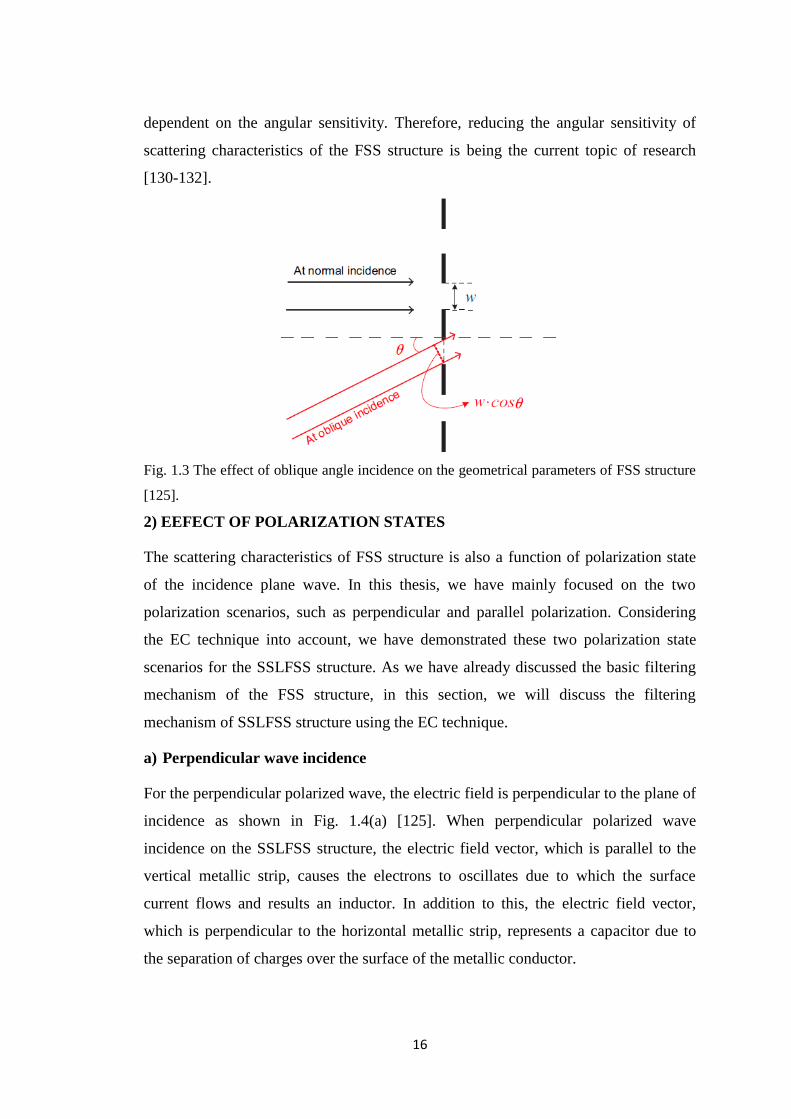
1) EFFECT OF AOIs
When a plane wave impinges on the FSS structure at an oblique angle, the width of
unit-cell metallic pattern and the inert-element gap between the unit-cells is reduced
by a factor of cosθ, where θ is the incidence angle as shown in Fig. 1.3 [125].
Therefore, the geometrical parameters of the FSS structure at the oblique incidence
differ from the scenario of the normal incidence, which also varies the scattering
characteristics of the FSS structure [126-128]. In this thesis, we have discussed the
effect of different AOIs on the resonance frequency of SSLFSS structure by EC
technique, which determine the equivalent inductive and capacitive behaviour of
SSLFSS structure as a function of θ [42, 129]. For practical scenario, the plane waves
are incidence on the FSS structure at different angles and the structure performance is
16
dependent on the angular sensitivity. Therefore, reducing the angular sensitivity of
scattering characteristics of the FSS structure is being the current topic of research
[130-132].
Fig. 1.3 The effect of oblique angle incidence on the geometrical parameters of FSS structure
[125].
2) EEFECT OF POLARIZATION STATES
The scattering characteristics of FSS structure is also a function of polarization state
of the incidence plane wave. In this thesis, we have mainly focused on the two
polarization scenarios, such as perpendicular and parallel polarization. Considering
the EC technique into account, we have demonstrated these two polarization state
scenarios for the SSLFSS structure. As we have already discussed the basic filtering
mechanism of the FSS structure, in this section, we will discuss the filtering
mechanism of SSLFSS structure using the EC technique.
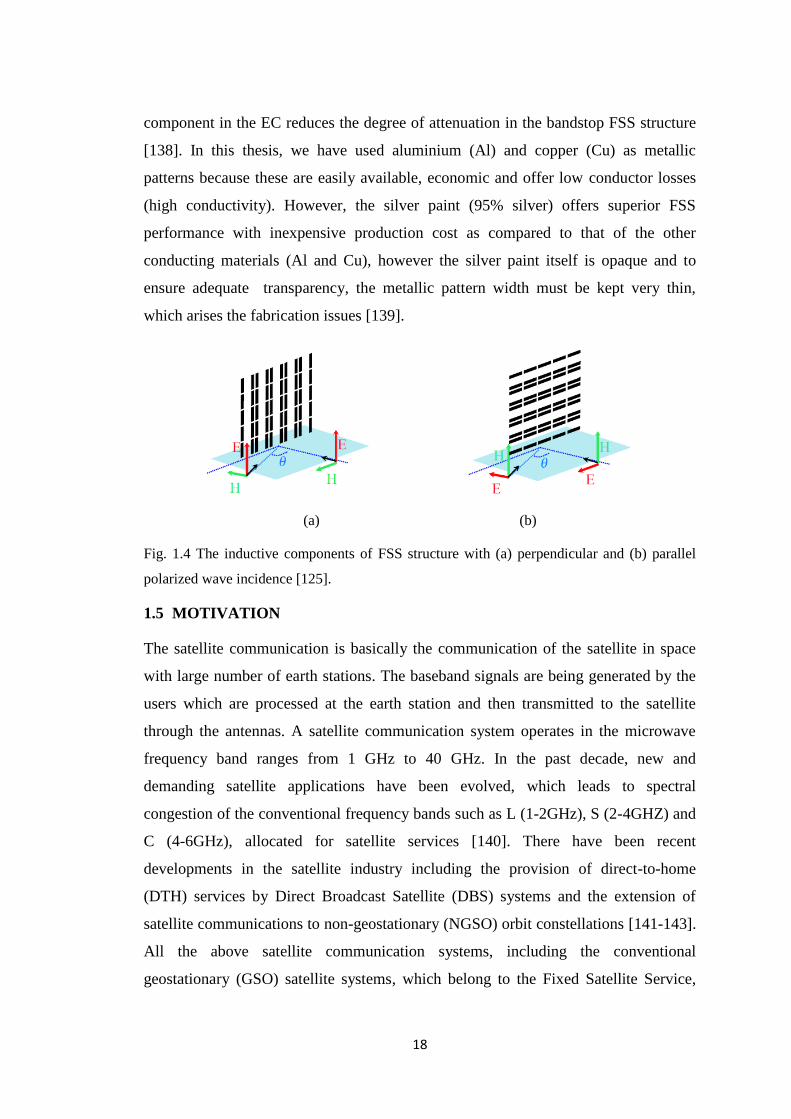
a) Perpendicular wave incidence
For the perpendicular polarized wave, the electric field is perpendicular to the plane of
incidence as shown in Fig. 1.4(a) [125]. When perpendicular polarized wave
incidence on the SSLFSS structure, the electric field vector, which is parallel to the
vertical metallic strip, causes the electrons to oscillates due to which the surface
current flows and results an inductor. In addition to this, the electric field vector,
which is perpendicular to the horizontal metallic strip, represents a capacitor due to
the separation of charges over the surface of the metallic conductor.
17
b) Parallel wave incidence
In parallel polarized wave, the electric field vector is parallel to the plane of incidence
as shown in Fig. 1.4(b) [125]. When parallel polarized wave incidence on the SSLFSS
structure, the electric field vector, which is parallel to the horizontal metallic strip,
causes the electrons to oscillates due to which the surface current flows and results an
inductor. In addition to this, the electric field vector, which is perpendicular to the
vertical metallic strip, represents a capacitor due to the separation of charges over the
surface of the metallic conductor. The patch type SSLFSS structure is represented as
the single series LC circuit shunted across the transmission line of the characteristics
impedance (Zo). In both the polarization states, the electric field vector is polarized
parallel to the conducting strip, which result an inductive component, however, the
currents induced on the conducting strip due to the oscillations of electrons are
different when plane wave incidence at oblique angles. This is because in the
perpendicular-incidence wave scenario, the electric field vector is always parallel to
the strip and excites the full length of each conducting strip irrespective of the
incidence angle and in parallel-incidence wave scenario, the electric field vector
arrives obliquely to the broadside of the strip, resulting in a shorter projected
conducting strip length as the incident angle increases. The variations of the scattering
characteristics of FSS structures with different AOIs and polarizations are undesirable
and a FSS structure with significant angular as well as polarization stability is
required for the various applications [133-136].
1.4D ELEMENT CONDUCTIVITY
When a FSS structure is illuminated by a plane wave, the surface current induced on
the conducting metallic pattern. These induced currents reradiate the electromagnetic
waves from the metallic pattern in the same way as the conductive strips inside a
rectangular waveguide [137]. In case of the perfect electric conductor (PEC) metallic
pattern, the SSLFSS structure is represented as series combination of inductor (L) and
capacitor (C) using EC technique. On the other hand, for a lossy metallic pattern, the
power dissipation occurs, which affect the overall frequency response of the FSS
structure and alters the equivalent circuit representation of the SSLFSS structure,
which has a resistor (R) in series with the L and C component. The resistive
18
component in the EC reduces the degree of attenuation in the bandstop FSS structure
[138]. In this thesis, we have used aluminium (Al) and copper (Cu) as metallic
patterns because these are easily available, economic and offer low conductor losses
(high conductivity). However, the silver paint (95% silver) offers superior FSS
performance with inexpensive production cost as compared to that of the other
conducting materials (Al and Cu), however the silver paint itself is opaque and to
ensure adequate transparency, the metallic pattern width must be kept very thin,
which arises the fabrication issues [139].
(a) (b)
Fig. 1.4 The inductive components of FSS structure with (a) perpendicular and (b) parallel
polarized wave incidence [125].
1.5 MOTIVATION
The satellite communication is basically the communication of the satellite in space
with large number of earth stations. The baseband signals are being generated by the
users which are processed at the earth station and then transmitted to the satellite
through the antennas. A satellite communication system operates in the microwave
frequency band ranges from 1 GHz to 40 GHz. In the past decade, new and
demanding satellite applications have been evolved, which leads to spectral
congestion of the conventional frequency bands such as L (1-2GHz), S (2-4GHZ) and
C (4-6GHz), allocated for satellite services [140]. There have been recent
developments in the satellite industry including the provision of direct-to-home
(DTH) services by Direct Broadcast Satellite (DBS) systems and the extension of
satellite communications to non-geostationary (NGSO) orbit constellations [141-143].
All the above satellite communication systems, including the conventional
geostationary (GSO) satellite systems, which belong to the Fixed Satellite Service,
19
gradually tend to employ higher frequency bands to satisfy the growing capacity
requirements [144]. In addition to this, on operating above 10 GHz frequency, the
atmospheric attenuations, which are mainly because of the humidity and oxygen,
increases, therefore one have to choose the selected frequency bands, where the
atmospheric attenuation is low. Therefore, the research has been focused on the
investigation of the satellite communication systems at the Ku band (12-18 GHz), Ka
band (26.5-40 GHz) and even at higher frequency bands. Moreover, the volume and
weight constraints imposed by the launch vehicle generally demand a satellite
communication antenna design using a single reflector to operate over multi-
frequency bands. One possible way is to design a feed, which operate at different
frequency bands, which results an inefficient solution. The researchers come up with a
more desirable way, which is the designing of a FSS structure to a reflector system,
which create different focal points and allow separate placement of feeds optimally
designed for each frequency band. The FSS structures have the essential
characteristics, which is transparent for one band of frequencies and reflective at other
frequency band. However, various researchers have discussed physical insight and
electromagnetic behaviour of variety of FSS structures using different numerical
techniques as reported in [16-22]. In satellite communication applications, the
frequency response of the FSS structures undergoes polarization variation in the
direction of electric field due to the Faraday rotation effect as wave propagates in the
ionosphere [23]. However, in realistic world, the electromagnetic waves propagating
through space exhibit different AOIs and polarizations, therefore, in order to design a
potential FSS structure in these respects, the structure must have a stable frequency
response with respect to transmission and reflection characteristics for different AOIs
and polarizations. The existing literatures in the microwave regime of the
electromagnetic spectrum discuss only about the investigation of the FSS structures
using different numerical techniques but not its synthesis, which is very important
aspect to find the values of the geometrical parameters of FSS structure in order to
meet the specific scattering characteristics. The motivation for the realization of this
thesis lies in the need for developing a simple synthesis technique to obtain the
geometrical parameters of SSLFSS structure. In addition to this, we have proposed
novel geometrical shapes of FSS structures, which provide significantly much better
20
scattering characteristics as compared to that of the various reported FSS structures.
In this thesis, the proposed geometrical shapes have provided the significant single-
band and multiband scattering characteristics in microwave regime of the
electromagnetic spectrum.
1.6 PROBLEM FORMULATION
The FSS structures have been investigated in the microwave regime of the
electromagnetic spectrum since past five decades. In the microwave regime, the
researchers have focused to develop the novel geometrical shapes of FSS structures,
which have the potential to provide significant frequency response as compared to
that of the reported FSS structures. In this regard, initially the focus was to design and
analyze the novel FSS structures, which exhibits single resonance (bandstop and
bandpass). Various simple geometries such as discussed in [43-50] have been
explored to provide the single-band frequency characteristics. Thereafter, several
researchers have investigated the loaded FSS structures [145-154], which have been
classified as active loaded and passive loaded FSS structures. An active loaded FSS
has been designed by implementing a tuning circuit as a part of FSS pattern to switch
the frequency response (reflections and transmission) from transmission to reflection
and vice-versa over the chosen frequency range [146-150]. However, these types of
the structures are difficult to fabricate because of the complexity and cost of
fabrication. On the other hand, the passive loaded FSS structures are of significant
importance because the reflection/ transmission bandwidth and the resonant frequency
is less sensitive to the angle of plane wave incidence. In addition to this, the
fabrication of passive loaded FSS structures is easier due to the reduced complexity
and cost of fabrication as compared to that of the active loaded FSS structure.
Therefore, various researchers [151-154] have studied the passive element loaded FSS
structures.
However, for the satellite communication applications, the FSS structure must be
simple, low profile, and provide the significant angular/polarization stability for wide
range of AOIs and different polarizations. With these aspects taken into consideration,
we have proposed simple passive loaded FSS structures, which provide the significant
scattering characteristics as compared to that of the other reported FSS structures in
21
the microwave regime of the electromagnetic spectrum. Moreover, in order to design
the multiband FSS structure for the satellite communication applications, a simplified
design, low profile and light weight FSS structure is the prime demand, therefore, in
this thesis, we have discussed multi-resonant element FSS structure, which provide
the multi-band frequency characteristics with significantly stable angular and
polarization response. Moreover, the following design issues have been taken into
consideration in order to propose the novel FSS structures.
Design, analysis and control of behavior of flat-screen FSS in S (2-4 GHz)-band,
and Ku (12-15 GHz)/Ka (24-28 GHz)-band,
Parametric optimization of FSS structure for significant reflection and transmission
characteristics in S, Ku and Ka-band,
Analysis to enhance approximately 10% bandwidth,
Prediction of the reflection and transmission characteristics with varying incident
angle of plane wave in the range of ± 50o,
Prediction of reflection and transmission characteristics with the variations in the
polarization (perpendicular and parallel) states, and
Validation of frequency responses using commercial simulators.
With the aforementioned design issues taken into consideration, we have discussed
the SSLFSS as well as proposed novel unit-cell FSS structures such as modified
circular ring FSS with four pairs of parallel straight conductors/slots and azimuthally
periodic wedge shaped metallic vane, which have been achieved through the passive
loading of the classical circular ring FSS structure. With the further geometrical
modifications in the proposed FSS structures, we have discussed single layer
multiband FSS structures (patch/aperture), which provide significant angular (up to
50o) and polarization (horizontal and vertical) insensitive response using
multiresonant approach.
1.7 THESIS ORGANIZATION
The remainder of thesis is organized as follows. Chapter 2 discusses the synthesis
technique of bandstop SSLFSS structure (without the dielectric substrate) and find
22
suitable applications in the fast analysis as well as fabrication of FSS structure.
Moreover, a way to control the reflection at any frequency is discussed, which find an
application in controlling the reflection level at any frequency. In addition to this, the
two simple, cheaper and lightweight FSS structures for satellite communications have
been investigated.
The Chapter 3 provides a detailed description of the issues related to the structural
transformation from SSLFSS to circular ring FSS structure. Further, the need to
develop a modified circular ring FSS from the geometrical variations in the classical
circular ring FSS structure has been discussed. In this Chapter, the effect of the
supporting dielectric to proposed FSS structure is also investigated.
Chapter 4 presents the extension of proposed synthesis technique for the bandpass
FSS, which is backed with the dielectric substrate and investigate the scattering
characteristics of the proposed bandpass FSS structure at S, Ku/Ka and X-band. At
each frequency of interest, the angular and polarization stability of proposed bandpass
FSS is also discussed. In addition to this, the frequency response of proposed
bandpass FSS structure is experimentally measured at X-band.
Chapter 5 explores the scattering characteristics such as resonance frequency and
bandwidth of proposed planar multiband FSS structures (slot-and patch-type) in the
microwave regime of the electromagnetic spectrum. The angular/polarization stability
and electric field distribution of the planar multiband FSS structure has been
discussed in the microwave regime of the electromagnetic spectrum.
Chapter 6 discusses the structure for bandstop and bandpass filtering characteristics.
It includes the radial optimization and performance evaluation of the structure with
respect to the wide range of AOIs and different polarization states. Finally, Chapter 7
concludes the thesis and recommends the possible future directions.