Embed Size (px)
Citation preview

Rev. (2008-09) by Luciano Gualà 111 -
William Stallings Computer Organization and Architecture
Chapter 12CPU Structure and Function
Rev. (2008-09) by Luciano Gualà 211 -
CPU Functions
• CPU must: Fetch instructions Decode instructions Fetch operands Execute instructions / Process data Store data Check (and possibly serve) interrupts

Rev. (2008-09) by Luciano Gualà 311 -
CPU Components
Control Unit
ALU
Registri
CP
U I
nte
rna
l Bu
s
Control Signals
PC
MAR
IR
MBRAC
Dat
a Li
nes
Add
ress
Lin
es
Con
trol
Lin
es

Rev. (2008-09) by Luciano Gualà 411 -
Kind of Registers
• User visible and modifiable General Purpose Data (e.g. accumulator) Address (e.g. base addressing, index addressing)
• Control registers (not visible to user) Program Counter (PC) Instruction Decoding Register (IR) Memory Address Register (MAR) Memory Buffer Register (MBR)
• State register (visible to user but not directly modifiable) Program Status Word (PSW)

Rev. (2008-09) by Luciano Gualà 511 -
Kind of General Purpose Registers
• May be used in a general way or be restricted to contains only data or only addresses
• address registers: e.g. segment pointers, indexing registers, stack pointer
• Advantages of general purpose registers Increase flexibility and programmer options Increase instruction size & complexity
• Advantages of specialized (data/address) registers Smaller (faster) instructions Less flexibility

Rev. (2008-09) by Luciano Gualà 611 -
How Many General Purposes Registers?
• Between 8 - 32• Fewer = more memory references• More does not reduce memory references

Rev. (2008-09) by Luciano Gualà 711 -
How many bits per register?
• Large enough to hold full address value• Large enough to hold full data value• Often possible to combine two data
registers to obtain a single register with a double length

Rev. (2008-09) by Luciano Gualà 811 -
State Registers
• Sets of individual bits e.g. store if result of last operation was zero or not
• Can be read (implicitly) by programs e.g. Jump if zero
• Can not (usually) be set by programs• There is always a Program Status Word (see later)• Possibly (for operating system purposes):
Memory page table (virtual memory) Process control blocks (multitasking)
• How to store control information? registers VS main memory

Rev. (2008-09) by Luciano Gualà 911 -
Program Status Word
• A set of bits, including condition code bits, giving the status of the program Sign of last result Zero Carry Equal Overflow Interrupt enable/disable Supervisor mode (allow to execute privileged
instructions)• Used by operating system (not available to user
programs)

Rev. (2008-09) by Luciano Gualà 1011 -
Example Register Organizations

Rev. (2008-09) by Luciano Gualà 1111 -
Instruction Cycle (with Interrupt)
Fetch Phase Execute Phase Interrupt Phase

Rev. (2008-09) by Luciano Gualà 1211 -
Instruction Cycle (with Indirect Addressing)
Rev. (2008-09) by Luciano Gualà 1311 -
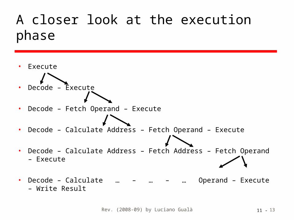
• Execute
• Decode – Execute
• Decode – Fetch Operand – Execute
• Decode – Calculate Address – Fetch Operand – Execute
• Decode – Calculate Address – Fetch Address – Fetch Operand – Execute
• Decode – Calculate … – … – … Operand – Execute – Write Result
A closer look at the execution phase

Rev. (2008-09) by Luciano Gualà 1411 -
Instruction Cycle State Diagram (with Indirection)

Rev. (2008-09) by Luciano Gualà 1511 -
Data Flow for Instruction Fetch
• PC contains address of next instruction• Sequence of actions needed to execute
instruction fetch:1. PC is moved to MAR2. MAR content is placed on address bus3. Control unit requests memory read4. Memory read address bus and places result on data
bus5. Data bus is copied to MBR6. MBR is copied to IR7. Meanwhile, PC is incremented by 1
• Action 7 can be executed in parallel with any other action after the first

Rev. (2008-09) by Luciano Gualà 1611 -
Diagrams representing Data Flows
• The previous example shows 7 distinct actions, each corresponding to a DF (= data flow)
• Distinct DFs are not necessarily executed at distinct time steps (i.e.: DFn and DFn+1 might be executed during the same time step)
• Large arrows in white represents DFs with a true flow of data
• Large hatched arrows represents DFs where flow of data acts as a control: only the more relevant controls are shown

Rev. (2008-09) by Luciano Gualà 1711 -
Data Flow Diagram for Instruction Fetch
IR MBR
ControlUnit
MAR
DataBus
AddressBus
ControlBus
Memory
CPU
MAR = Memory Address RegisterMBR = Memory Buffer RegisterIR = Instruction RegisterPC = Program Counter
PC2
3
3
4
4
5
1
6
7
Rev. (2008-09) by Luciano Gualà 1811 -
Data Flow for Data Fetch: Immediate and Register Addressing
• ALWAYS: IR is examined to determine addressing mode
• Immediate addressing: The operand is already in IR
• Register addressing: Control unit requests read from register
selected according to value in IR

Rev. (2008-09) by Luciano Gualà 1911 -
Data Flow Diagram for Data Fetch with Register Addressing
IR
ControlUnit
Registers
DataBus
AddressBus
ControlBus
CPU
MAR = Memory Address RegisterMBR = Memory Buffer RegisterIR = Instruction RegisterPC = Program Counter

Rev. (2008-09) by Luciano Gualà 2011 -
Data Flow for Data Fetch:Direct Addressing• Direct addressing:
1. Address field is moved to MAR2. MAR content is placed on address bus3. Control unit requests memory read4. Memory reads address bus and places result
on data bus5. Data bus (= operand) is copied to MBR

Rev. (2008-09) by Luciano Gualà 2111 -
Data Flow Diagram for Data Fetch with Direct Addressing
MBR
ControlUnit
MAR
DataBus
AddressBus
ControlBus
Memory
CPU
MAR = Memory Address RegisterMBR = Memory Buffer RegisterIR = Instruction RegisterPC = Program Counter
2
3
3
4
4
5
1
IR

Rev. (2008-09) by Luciano Gualà 2211 -
Data Flow for Data Fetch: Register Indirect Addressing
• Register indirect addressing:1. Control unit requests read from register
selected according to value in IR2. Selected register value is moved to MAR3. MAR content is placed on address bus4. Control unit requests memory read5. Memory reads address bus and places result
on data bus6. Data bus (= operand) is moved to MBR

Rev. (2008-09) by Luciano Gualà 2311 -
Data Flow Diagram for Data Fetch with Register Indirect Addressing
IR MBR
ControlUnit
MAR
DataBus
AddressBus
ControlBus
Memory
CPU
MAR = Memory Address RegisterMBR = Memory Buffer RegisterIR = Instruction RegisterPC = Program Counter
Registers
3
4
4
5
5
6
1
1
2
Rev. (2008-09) by Luciano Gualà 2411 -
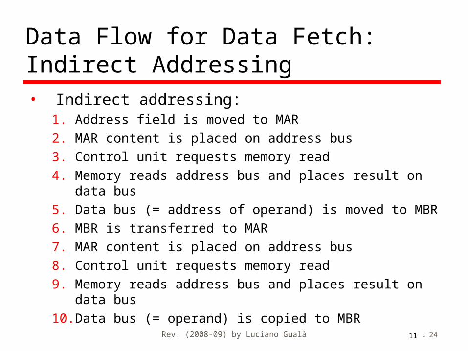
Data Flow for Data Fetch: Indirect Addressing• Indirect addressing:
1. Address field is moved to MAR2. MAR content is placed on address bus3. Control unit requests memory read4. Memory reads address bus and places result on data
bus5. Data bus (= address of operand) is moved to MBR6. MBR is transferred to MAR7. MAR content is placed on address bus8. Control unit requests memory read9. Memory reads address bus and places result on data
bus10. Data bus (= operand) is copied to MBR

Rev. (2008-09) by Luciano Gualà 2511 -
Data Flow Diagram for Data Fetch with Indirect Addressing
MBR
ControlUnit
MAR
DataBus
AddressBus
ControlBus
Memory
CPU
MAR = Memory Address RegisterMBR = Memory Buffer RegisterIR = Instruction RegisterPC = Program Counter
2 - 7
3 - 8
3 - 8
4 - 9
4 - 9
5 - 10
1
IR
6

Rev. (2008-09) by Luciano Gualà 2611 -
Data Flow for Data Fetch: Relative Addressing• Relative addressing (a form of
displacement):1. Address field is moved to ALU 2. PC is moved to ALU3. Control unit requests sum to ALU4. Result from ALU is moved to MAR5. MAR content is placed on address bus6. Control unit requests memory read7. Memory reads address bus and places result on
data bus8. Data bus (= operand) is copied to MBR

Rev. (2008-09) by Luciano Gualà 2711 -
Data Flow Diagram for Data Fetch with Relative Addressing
IR MBR
ControlUnit
MAR
DataBus
AddressBus
ControlBus
Memory
CPU
MAR = Memory Address RegisterMBR = Memory Buffer RegisterIR = Instruction RegisterPC = Program CounterALU = Arithmetic Logic Unit
ALU
PC
5
6
6
7
7
8
1
2
3
4

Rev. (2008-09) by Luciano Gualà 2811 -
Data Flow for Data Fetch: Base Addressing• Base addressing (a form of displacement):
1. Control unit requests read from register selected according to value in IR (explicit selection)
2. Selected register value is moved to ALU3. Address field is moved to ALU4. Control unit requests sum to ALU5. Result from ALU is moved to MAR6. MAR content is placed on address bus7. Control unit requests memory read8. Memory reads address bus and places result on data
bus9. Result (= operand) is moved to MBR

Rev. (2008-09) by Luciano Gualà 2911 -
Data Flow Diagram for Data Fetch with Base Addressing
IR MBR
ControlUnit
MAR
DataBus
AddressBus
ControlBus
Memory
CPU
MAR = Memory Address RegisterMBR = Memory Buffer RegisterIR = Instruction RegisterPC = Program CounterALU = Arithmetic Logic Unit
Registers
1
1
2
3
5
ALU
4
6
7
7
8
8
9

Rev. (2008-09) by Luciano Gualà 3011 -
Data Flow for Data Fetch: Indexed Addressing
• Same data flow as Base addressing • Indexed addressing (a form of displacement):
1. Control unit requests read from register selected according to value in IR (explicit selection)
2. Selected register value is moved to ALU3. Address field is moved to ALU4. Control unit requests sum to ALU5. Result from ALU is moved to MAR6. MAR content is placed on address bus7. Control unit requests memory read8. Memory reads address bus and places result on data
bus9. Result (= operand) is moved to MBR

Rev. (2008-09) by Luciano Gualà 3111 -
Data Flow Diagram for Data Fetch with Indexed Addressing
• The diagram is the same as for Base addressing

Rev. (2008-09) by Luciano Gualà 3211 -
Data Flow for Data Fetch with indirection and displacement
• Two different combinations of displacement and indirection (pre-index and post-index)
• See chapter 11 for the logical diagrams• The data flow is a combination of what
happens with the two techniques• Try drawing the data flow diagrams
yourself !

Rev. (2008-09) by Luciano Gualà 3311 -
Data Flow for Execute
• May take many forms• Depends on the actual instruction being
executed• May include
Memory read/write Input/Output Register transfers ALU operations

Rev. (2008-09) by Luciano Gualà 3411 -
Data Flow for Interrupt
• Current PC has to be saved (usually to stack) to allow resumption after interrupt and execution has to continue at the interrupt handler routine
1. Save the content of PCa. Contents of PC is copied to MBRb. Special memory location (e.g. stack pointer) is loaded to MARc. Contents of MAR and MBR are placed, respectively, on address and
data busd. Control unit requests memory writee. Memory reads address and data bus and store to memory location
2. PC is loaded with address of the handling routine for the specific interrupta. Move to MAR the address into the interrupt vector for the specific
interruptb. MAR content is placed on address busc. Control unit requests memory readd. Memory reads address bus and places result on data buse. Data bus is copied to MBRf. MBR is moved to PC
• Next instruction (first of the specific interrupt handler) can now be fetched

Rev. (2008-09) by Luciano Gualà 3511 -
Data Flow Diagram for Interrupt
MAR
DataBus
AddressBus
ControlBus
Memory
CPU
MAR = Memory Address RegisterMBR = Memory Buffer RegisterIR = Instruction RegisterPC = Program Counter
Registers
PC
ControlUnit
MBR
1b
1a
1b
1c - 2b
1c
1d - 2c
1d - 2c
1e
1e - 2d
2a
2d
2e2f

Rev. (2008-09) by Luciano Gualà 3611 -
Istruction pipelining
• similar to the use in an assembly line in a manufacturing plant product goes through various stages of
production products at various stages can be worked on
simultaneously
• in a pipeline, new inputs are accepted at one end before previously accepted inputs appear as outputs at the other end

Rev. (2008-09) by Luciano Gualà 3711 -
Prefetch
• Fetch accesses main memory• Execution usually does not access main
memory• CPU could fetch next instruction during
the execution of current instruction• Requires two sub-parts in CPU able to
operate independently• Called instruction prefetch
How much does the performance improve?

Rev. (2008-09) by Luciano Gualà 3811 -
Improved Performance
• But performance is not doubled: Fetch usually shorter than execution
• Prefetch more than one instruction?
Any conditional jump or branch means that prefetched instructions may be useless
• Performance can be improved by adding more stages in instruction processing ... … and more independent sub-parts in CPU

Rev. (2008-09) by Luciano Gualà 3911 -
Pipelining
• Instruction cycle can be decomposed in elementary phases, for example: FI: Fetch instruction DI: Decode instruction CO: Calculate operands (i.e. calculate EAs) FO: Fetch operands EI: Execute instructions WO: Write output
• Pipelining improves performance by overlapping these phases (ideally can all be overlapped)

Rev. (2008-09) by Luciano Gualà 4011 -
Timing of Pipeline
Set up time Time

Rev. (2008-09) by Luciano Gualà 4111 -
Some remarks
• An instruction can have only some of the six phases
• We are assuming that all the phases can be performed in parallel e.g., no bus conflicts, no memory conflicts…
• the maximum improvement is obtained when the phases take more or less the same time
Rev. (2008-09) by Luciano Gualà 4211 -
A general principle
• The more overlapping phases are in a pipeline the more additional processing is needed to manage each phase and synchronization among phases Logical dependencies between phases
• There is a trade-off between number of phases and speed-up of instruction execution

Rev. (2008-09) by Luciano Gualà 4311 -
Controlflow (1)

Rev. (2008-09) by Luciano Gualà 4411 -
Branch in a Pipeline (1)
Branch Penalty Time
• Instruction 3 is a conditional branch to instruction 15
WO

Rev. (2008-09) by Luciano Gualà 4511 -
Controlflow (2)
EmptyBack Pipe
• But an unconditional branch might be managed earlier than EI phase

Rev. (2008-09) by Luciano Gualà 4611 -
Branch in a Pipeline (2)
• The unconditional branch is managed after CO phase
Branch Penalty Time Branch PenaltyTime
FO EI WO

Rev. (2008-09) by Luciano Gualà 4711 -
Controlflow (3)
EmptyBack Pipe
• But conditional branches still have a large penalty
Rev. (2008-09) by Luciano Gualà 4811 -
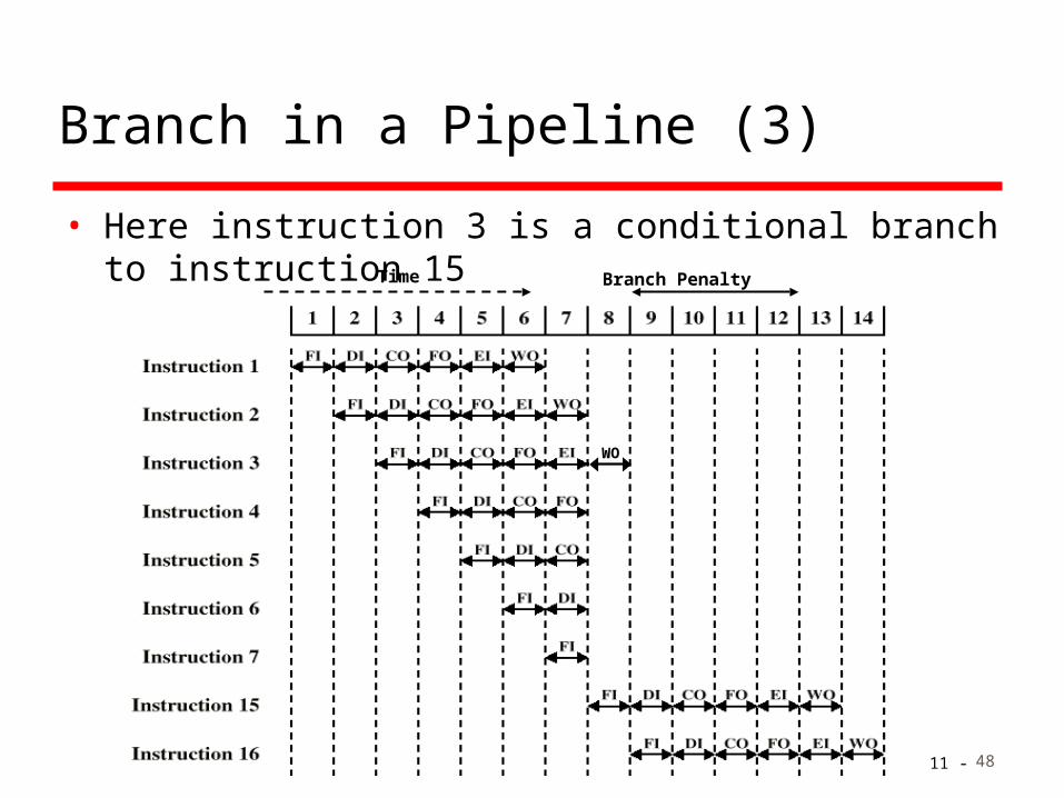
Branch in a Pipeline (3)
Branch Penalty Time
• Here instruction 3 is a conditional branch to instruction 15
WO

Rev. (2008-09) by Luciano Gualà 4911 -
Dealing with Branches
• Multiple Streams• Prefetch Branch Target• Loop buffer• Branch prediction• Delayed branching
Rev. (2008-09) by Luciano Gualà 5011 -
Multiple Streams
• Have two pipelines• Prefetch each branch into a separate pipeline• Use appropriate pipeline
• Leads to bus & register contention (only the sub-parts making up the pipeline are doubled)
• Additional branches entering the pipeline lead to further pipelines being needed
Rev. (2008-09) by Luciano Gualà 5111 -
Prefetch Branch Target
• Target of branch is prefetched in addition to instructions following branch and stored in an additional dedicated register
• Keep target until branch is executed• Used by IBM 360/91

Rev. (2008-09) by Luciano Gualà 5211 -
Loop Buffer
• Very fast memory internal to CPU• Record the last n fetched instructions• Maintained by fetch stage of pipeline• Check loop buffer before fetching from
memory• Very good for small loops or close jumps• The same concept as cache memory• Used by CRAY-1

Rev. (2008-09) by Luciano Gualà 5311 -
Branch Prediction (1)
• Predict never taken Assume that jump will not happen Always fetch next instruction 68020 & VAX 11/780 VAX will not prefetch after branch if a page
fault would result (O/S v CPU design)
• Predict always taken Assume that jump will happen Always fetch target instruction

Rev. (2008-09) by Luciano Gualà 5411 -
Branch Prediction (2)
• Predict by Opcode Some instructions are more likely to result in a
jump than others Can get up to 75% success
• Taken/Not taken switch Based on previous history of the instruction Good for loops Where do we store the history of the
instruction?• cache

Rev. (2008-09) by Luciano Gualà 5511 -
Branch Prediction State Diagram

Rev. (2008-09) by Luciano Gualà 5611 -
Delayed Branch
• Do not take jump until you have to• Rearrange instructions
• Used for RISC architectures
RISC: reduced instructions set computerCISC: complex instructions set computer


![Sistemi Operativi [William Stallings]](https://img.pdfslide.net/doc/110x75/543cd117b1af9fc42e8b4811/sistemi-operativi-william-stallings.jpg)