Embed Size (px)
Citation preview
1111111111111111111inmm1111111111u~(12) United States Patent
Jansen et al.
(54) BEARINGLESS FLYWHEEL SYSTEMS,WINDING AND CONTROL SCHEMES, ANDSENSORLESS CONTROL
(71) Applicant: The United States of America, asrepresented by the Administrator ofthe National Aeronautics and SpaceAdministration, Washington, DC (US)
(72) Inventors: Ralph H Jansen, Westlake, OH (US);Larry M Trase, Litchfield, OH (US);Timothy P Dever, Westlake, OH (US);Peter E Kascak, Cleveland, OH (US);Thomas G Kraft, Cleveland, OH (US)
(73) Assignee: The United States of America asRepresented by the Administrator ofNational Aeronautics and SpaceAdministration, Washington, DC (US)
(*) Notice: Subject to any disclaimer, the term of thispatent is extended or adjusted under 35U.S.C. 154(b) by 672 days.
(21) Appl. No.: 13/723,598
(22) Filed: Dec. 21, 2012
(65) Prior Publication Data
US 2014/0028132 Al Jan. 30, 2014
Related U.S. Application Data
(60) Provisional application No. 61/631,443, filed on Dec.23, 2011, provisional application No. 61/583,425,filed on Jan. 5, 2012, provisional application No.61/584,364, filed on Jan. 9, 2012.
(51) Int. Cl.H02K 7/02 (2006.01)H02K 5/00 (2006.01)H02K 7/09 (2006.01)
(io) Patent No.: US 9,515,531 B2(45) Date of Patent: Dec. 6, 2016
H02P 9/02 (2006.01)H02K 5/16 (2006.01)F16C 32104 (2006.01)
(52) U.S. Cl.CPC H02K 5/00 (2013.01); H02K 5/16 (2013.01);
H02K 7/025 (2013.01); H02K 7/09 (2013.01);H02P 9/02 (2013.01); F16C 3210497
(2013.01); Y02E 60116 (2013.01)(58) Field of Classification Search
CPC ............. H02K 7/09; H02K 5/16; H02K 7/025USPC ............................................................ 310/74See application file for complete search history.
(56) References Cited
U.S. PATENT DOCUMENTS
4,077,678 A 3/1978 Studer et al.4,370,004 A 1/1983 Morikawa et al.4,412,170 A 10/1983 Roesel, Jr.4,870,310 A 9/1989 Triplett5,703,423 A 12/1997 Fukao et al.5,747,907 A 5/1998 Miller5,760,508 A 6/1998 Jennings et al.5,969,457 A 10/1999 Clifton et al.
(Continued)
Primary Examiner Hanh Nguyen(74) Attorney, Agent, or Firm Robert H. Earp, III
(57) ABSTRACT
Flywheel systems are disclosed that provide increasedenergy density and operational effectiveness. A first bear-ingless motor and a second bearingless motor may beconfigured to simultaneously suspend the central rotor in aradial direction and to rotate the central rotor. However,certain implementations may have one motor or more thantwo motors, depending on the design. A plurality of theflywheel systems may be collectively controlled to performcommunity energy storage with higher storage capacitiesthan individual flywheel systems.
20 Claims, 25 Drawing Sheets
https://ntrs.nasa.gov/search.jsp?R=20170000205 2018-07-17T18:15:45+00:00Z

US 9,515,531 B2Page 2
(56) References Cited
U.S. PATENT DOCUMENTS
6,019,319 A 2/2000 Falbel6,166,469 A * 12/2000 Osama et al . ............... 310/90.56,166,472 A 12/2000 Pinkerton et al.6,262,505 B1 7/2001 Hockney et al.6,388,347 B1 * 5/2002 Blake et al . .................... 310/746,703,735 B1 * 3/2004 Gabrys ........................ 310/90.56,707,187 B1 3/2004 Gabrys6,798,092 B1 * 9/2004 Gabrys et al . .................. 310/456,825,588 B2 11/2004 Gabrys et al.6,867,520 B2 3/2005 Jennings6,897,587 B1 * 5/2005 McMullen et al........... 310/90.56,927,517 B2 * 8/2005 Brunet et al ................. 310/90.57,608,951 B2 10/2009 Potter et al.8,242,649 B2 8/2012 Fradella8,314,527 B2 11/2012 Wang
2 00 6/023 80 53 Al 10/2006 Kascak et al.2008/0303363 Al 12/2008 Alston2010/0231076 Al 9/2010 Chiba et al.2010/0282528 Al 11/2010 Palti2010/0283340 Al* 11/2010 Fradella .......................... 310/742012/0187922 Al 7/2012 Dubois et al.2012/0198960 Al 8/2012 Dubois et al.
* cited by examiner
U.S. Patent Dec. 6, 2016 Sheet 1 of 25
F I G. 1111\11\
ME
141
US 9,515,531 B2
150
U.S. Patent Dec. 6, 2016
200'
US 9,515,531 B2
U.S. Patent Dec. 6, 2016 Sheet 3 of 25 US 9,515,531 B2
U.S. Patent Dec. 6, 2016 Sheet 4 of 25 US 9,515,531 B2
U.S. Patent Dec. 6, 2016 Sheet 5 of 25 US 9,515,531 B2
U.S. Patent Dec. 6, 2016 Sheet 6 of 25 US 9,515,531 B2
U.S. Patent Dec. 6, 2016 Sheet 7 of 25 US 9,515,531 B2
U.S. Patent Dec. 6, 2016 Sheet 8 of 25 US 9,515,531 B2
U.S. Patent Dec. 6, 2016 Sheet 9 of 25
U.S. Patent Dec. 6, 2016 Sheet 10 of 25 US 9,515,531 B2
NCD
U.S. Patent Dec. 6, 2016 Sheet 11 of 25 US 9,515,531 B2
U.S. Patent Dec. 6, 2016 Sheet 12 of 25 US 9,515,531 B2
r_
1200
FIG. 12
spat
ial ph
ase-a MMF wav
e Qa
.=1)
0
50
100
150
200
250
300
350
spat
ial ph
ase-b MMF wav
e Qb=1)
1 0 -10
50
im
150
200
250
300
350
spat
ial ph
ase-c MMF wav
e Qc=1)
1 0L--7, /1\/.
,-10
50
100
150
200
250
300
350
U.S. Patent Dec. 6, 2016 Sheet 14 of 25 US 9,515,531 B2
1300
6
Vol
12 13 14 15 16 17 18
---ova2-Phase A
1 2 3 4 5 6 7 8 9 10
Vbl
112 3 4 5
VC3- VCl+c
Phase B
12 13 14 15 16 17 18
9 10 11 12 13 14 15 16 17 18
(Cl- Vc2* VC2- VC3*Phase C
Related art
Figure 13
1400
spafiel p
hase
-at MMF
5 0 5 1 0
100
2m
300
spatial phwa bl MMF
Q5 0 M5 a
1m
an
~n
spatial ptmm ct MMF
0.5 0
0.5 10
103
100
xn
FIG. 14
spotial p
hase a2 MMF
0.5 0
05 0
100
200
sp01fo1 ph3sa.b2 MMF
).5 0 1.5 0
100
2m
inn
spaw pha
se-O MMF
RELATED AR1
sp011o1 phase-03 MMF
0.5
05 a
tmmn
aoo
apat
ial p
haaa W MMF
spatial ph
ase-c3 MMF
0.5 0 10
100
200
300
Zi
1500
IV(Cl.A2,B2)
170°
_
FIG. 15
I!I(
B1,C
1,A2
)
130°
MOM
B2 (te0ry ~~
C2 CAW)
V(A2,B2,C2)
rr
210°
VI(B2,C2,A3)
w
II(A
1,B1
,C1)
/.
c2 w
A3 OAM
1
1 t
!
11 /
1/
1r
250°
290°
270%
VII(C2,A3,B3)
I(C3
,A1,
81)
B3,C3,A9)
Vlll(A3,B3,C3)
U.S. Patent Dec. 6, 2016 Sheet 17 of 25 US 9,515,531 B2
1600
Pole Pair I
4ii
i
1 14
b1+ b1—
Pole Pair II
(?i~i0 1
1
11 1I
a2+ a2-
7 (/10 11 12
I
b2+ b2-
Figure 16
Pole Pair III
13 14 n15 16 17 118
I I
a3+ a3-
14 14 15 16 17 1811b3+ b3-
U.S. Patent Dec. 6, 2016 Sheet 18 of 25 US 9,515,531 B2
~V'f
n
U.S. Patent Dec. 6, 2016 Sheet 19 of 25
-R-
-R-
~P-
~-,,A
US 9,515,531 B2
;~I''d
IN
46
U.S. Patent Dec. 6, 2016 Sheet 20 of 25 US 9,515,531 B2
2000
FIG.20
Vl(Clp, Bin, A2p) go , V(Aln, Cop, Bin)
Vll(89 n,
A2p, C1 n) 11
13°
60e IV(Sl p, Al n Cl p)
VIN(A2p, Cl n,
82p) 130 ,
~~J!
, 5C3°
Ill(C3n, Btp, Ain)
1500
~'~
~11J
r r
30°
~
IX(Cl n, B2p, A2n)
#1 ~{1 t
r~ J'(661
Can, Sip)
amp (180
1
'eIl(Alp,
~#~
{°
X(82p, A2n, C2p) 18
f1°
—
N ° 1
(B3n
,A1p
,C3n
)_
351D°
a2+e
(?YQ'V
JaD €3M
#
Xl(A2n, Up, B2n)
{ Ca
r
Ain ("an
t ~
N.
XVIII(C3p, Ban, Alp)
'` '
2100'
r
J1
~
330*
r !
~
Xll(C2p, Ben, A3p) 2W
1Jtt
310*
XVII(A3n, Cap, 83n)
25W
2913
°
XIII(82n, A3p, C2n)
XVl(B3p, A3n, Cap)
WOO
XIV(A3p, C2n, 83p)
XV(C2n, Bap, A3n)
U.S. Patent Dec. 6, 2016 Sheet 22 of 25 US 9,515,531 B2
2100
Figure 21
U.S. Patent Dec. 6, 2016 Sheet 23 of 25 US 9,515,531 B2
2200
Current model
~s
kr i I exr
~s
arctgO,nArd) Xr
is
Figure 22
Rs Us
P!UCOmp Voltage model
~s
Xr
U.S. Patent Dec. 6, 2016 Sheet 24 of 25 US 9,515,531 B2
Figure
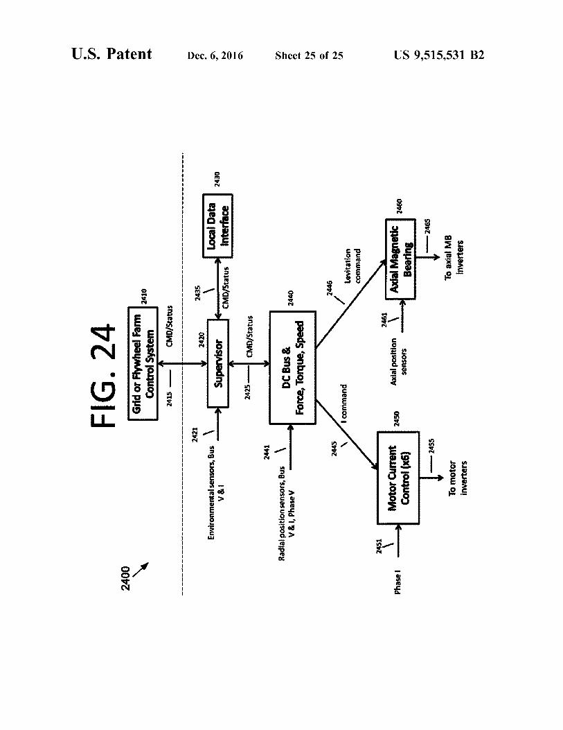
FIG. 24
b
2400
Grid
or Flywheel Farm
2410
Control S
ystem
2415 —
CMD/Status
------------------------------------------------- ----------------------------------------------
2421
2435
2420
d
Environmental s
enso
rs, Bus
,
Local Data
V & i
supervisor
2430
CMD/
Stat
us
Intterface
n' 0 a2425 —
T CMD
/Sta
tus
2441
Radial position s
enso
rs, Bus
V & i, Phase V
DC Bus &
2440
Forc
e, Torq
ue, Speed
N 0
2445
`2 446
Nt
1 command
Levi
tati
oncommand
7
2451
z4e1
Phase i -~
Motor Cu
rren
t 24
50Axial position ,
Axial M
agne
tic U.
Cont
rol (XG)
sensors
Bear
ing
---2455
2fts
To mot
orTo axial MB
inve
rter
sin
vert
ers
N
US 9,515,531 B2
BEARINGLESS FLYWHEEL SYSTEMS,WINDING AND CONTROL SCHEMES, AND
SENSORLESS CONTROL
CROSS REFERENCE TO RELATEDAPPLICATIONS
This application claims the benefit of U.S. ProvisionalApplication Ser. Nos. 61/631,443, filed on Dec. 23, 2011,61/583,425, filed on Jan. 5, 2012, and 61/584,364, filed onJan. 9, 2012. The subject matter of these earlier filedprovisional patent applications is hereby incorporated byreference in its entirety.
ORIGIN OF THE INVENTION
The invention described herein was made by employeesof the United States Government and may be manufacturedand used by or for the Government for Government pur-poses without the payment of any royalties thereon ortherefore.The invention described herein was also made in the
performance of work under a NASA contract and is subjectto the provisions of Section 305 of the National Aeronauticsand Space Action of 1958, Public Law 85-568 (72 Star. 435;42 U.S.C. 2457).
FIELD
The present invention generally pertains to flywheel sys-tems, and more specifically, to flywheel systems with abearingless motor/generator ("MG"), flywheel winding andcontrol schemes, and sensorless pole-pair separated bear-ingless motor/generators.
BACKGROUND
Flywheel systems for power storage include a rotor thatstores energy when rotated, a motor/generator ("MG") thatconverts energy between electrical and mechanical forms,and a bearing system that supports the rotating components.However, current flywheel-based energy storage devices areunable to provide power continuously for greater than fifteenminutes and are still too expensive for wide acceptance. Forinstance, the best conventional system available from theflywheel industry provides power for approximately twominutes, and the best available solution on grid runs forapproximately fifteen minutes. Accordingly, an improvedsystem design having a lower cost and higher reliability maybe beneficial. Also, reducing the mass and volume andincreasing the power density over conventional systems maybe beneficial.
SUMMARY
Certain embodiments of the present invention may beimplemented and provide solutions to the problems andneeds in the art that have not yet been fully solved byconventional flywheel systems. For example, certainembodiments of the present invention drive a flywheel (i.e.,a central rotor) with a bearingless motor/generator ("MG").Such embodiments may entirely eliminate a conventionalmechanical or magnetic bearing system, which leads to areduction in mass and cost savings.Some embodiments may employ a control approach that
provides improved performance for bearingless MGs byresolving gaps in spatial magnetomotive force ("MMF")
2generation. Stated differently, the control approach generatessymmetrical levitation forces. Certain embodiments maygather position and rotation information without using spe-cific sensors for the task, which reduces mass and cost.
5 In one embodiment of the present invention, an apparatusincludes a first bearingless motor and a second bearinglessmotor and an axial magnetic bearing configured to provideaxial control. The first bearingless motor and the secondbearingless motor are configured to suspend the central rotor
10 in a radial direction and to rotate the central rotor.In another embodiment of the present invention, an appa-
ratus includes a bearingless motor, an axial magnetic bearingconfigured to provide axial control, and a central rotor. The
15 bearingless motor and the axial magnetic bearing are con-figured to suspend the central rotor from above in a pendu-lum configuration.
In yet another embodiment of the present invention, acommunity energy storage system includes a plurality of
20 flywheel systems. The community energy storage systemalso includes an electronic control system configured tocontrol the plurality of flywheel systems. The communityenergy storage system is configured to provide communityenergy storage to a plurality of energy consumers.
25
BRIEF DESCRIPTION OF THE DRAWINGS
In order that the advantages of certain embodiments of theinvention will be readily understood, a more particular
3o description of the invention briefly described above will berendered by reference to specific embodiments that areillustrated in the appended drawings. While it should beunderstood that these drawings depict only typical embodi-ments of the invention and are not therefore to be considered
35 to be limiting of its scope, the invention will be describedand explained with additional specificity and detail throughthe use of the accompanying drawings, in which:
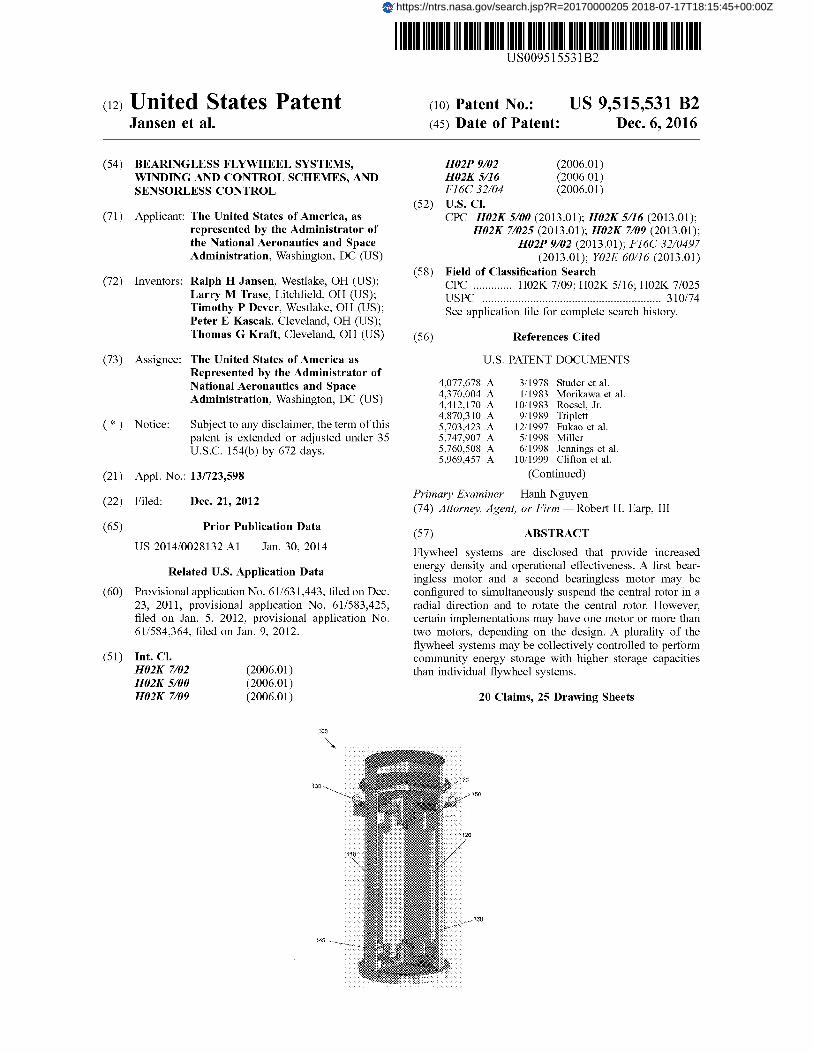
FIG. 1 illustrates a perspective cutaway view of a cylin-drical flywheel system, according to an embodiment of the
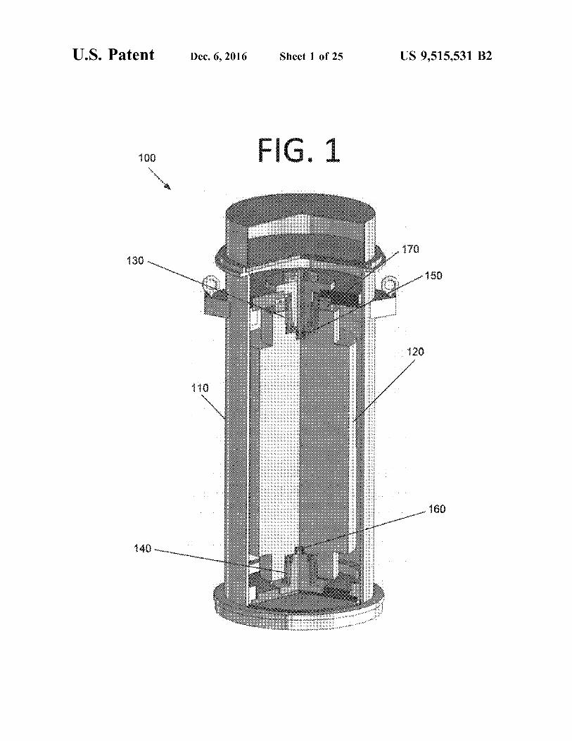
40 present invention.FIG. 2 illustrates a side view of a cylindrical flywheel
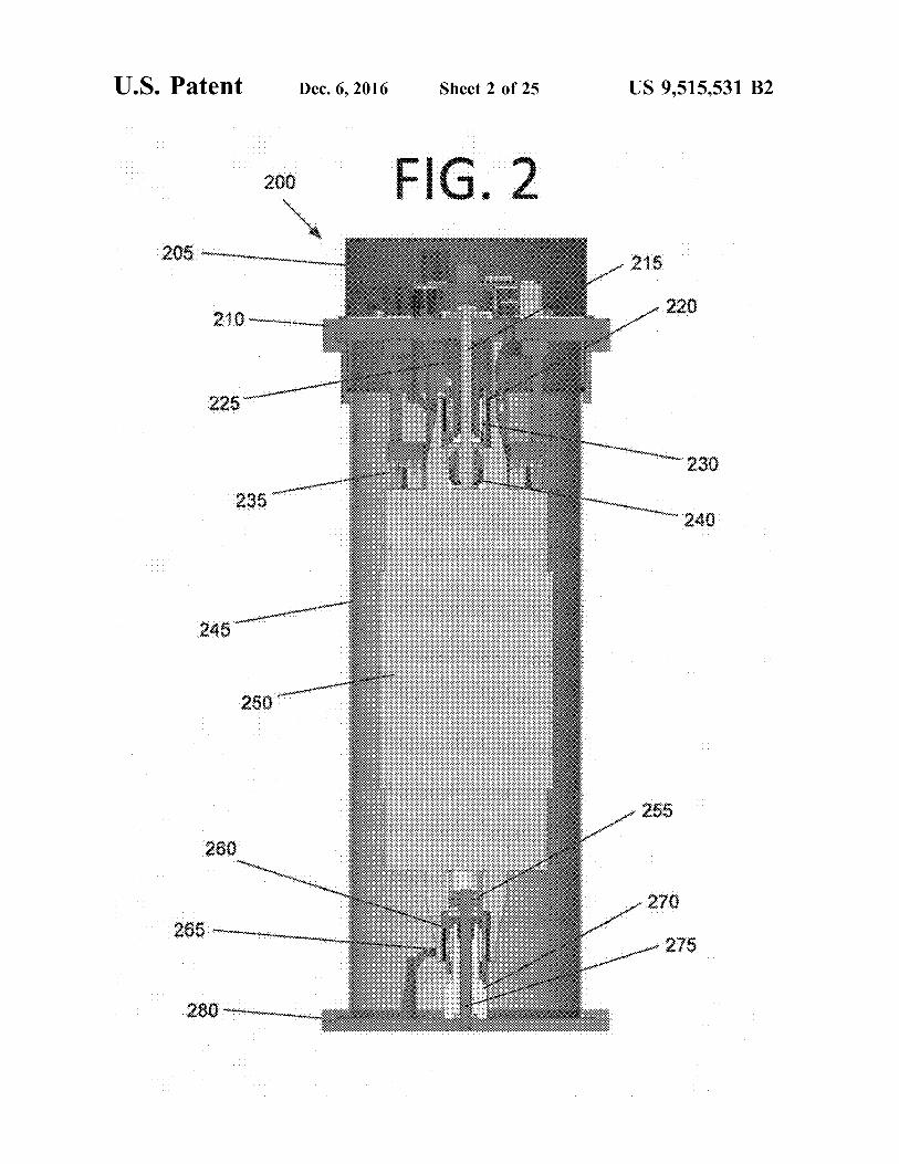
system, according to an embodiment of the present inven-tion.FIG. 3 illustrates a side view of an upper portion of a
45 cylindrical flywheel system, according to an embodiment ofthe present invention.
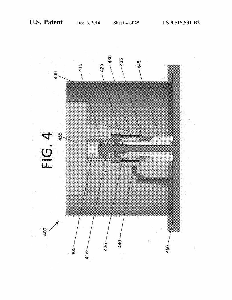
FIG. 4 illustrates a side view of a lower portion of acylindrical flywheel system, according to an embodiment ofthe present invention.
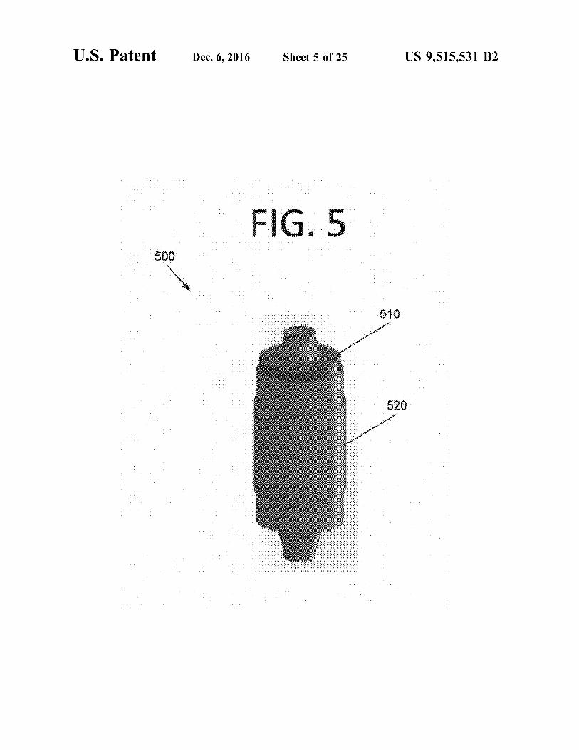
50 FIG. 5 illustrates a side perspective view of an axialmagnetic bearing ("AMB") that shows the location of theAMB on a rotor, according to an embodiment of the presentinvention.
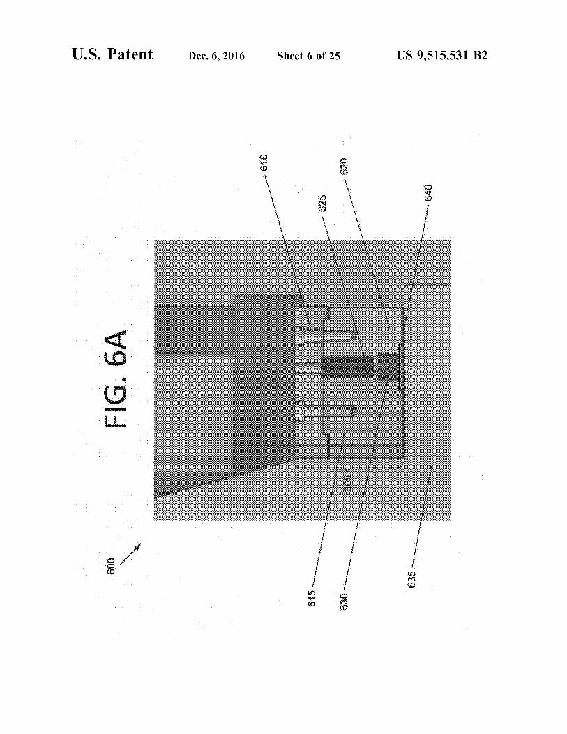
FIG. 6A illustrates a side view of an AMB, according to55 an embodiment of the present invention.
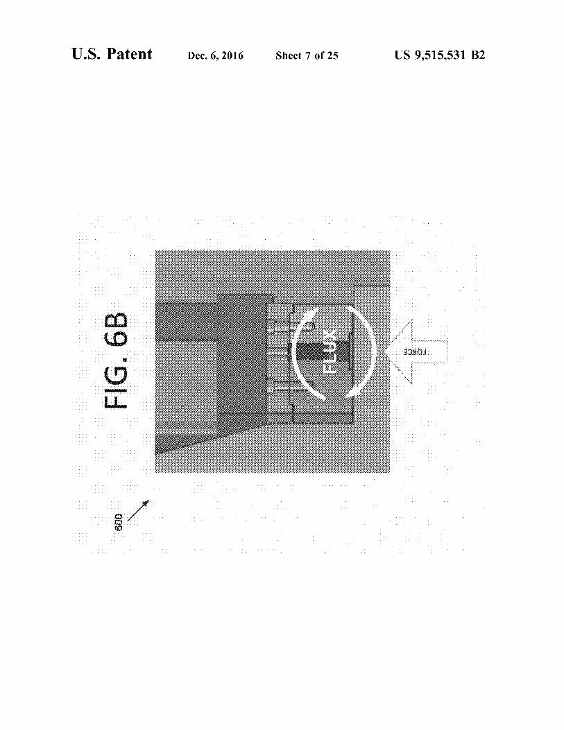
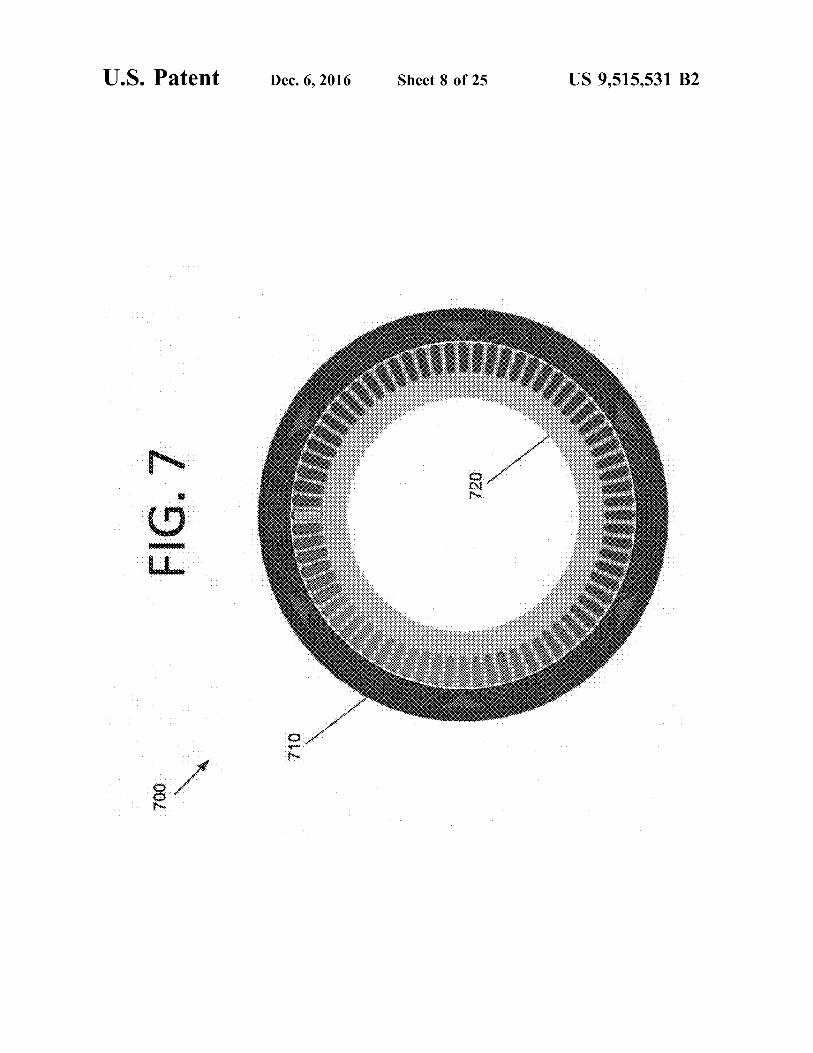
FIG. 6B illustrates a side view of forces acting on theAMB of FIG. 6A, according to an embodiment of thepresent invention.FIG. 7 illustrates a cross-sectional view of a cylindrical
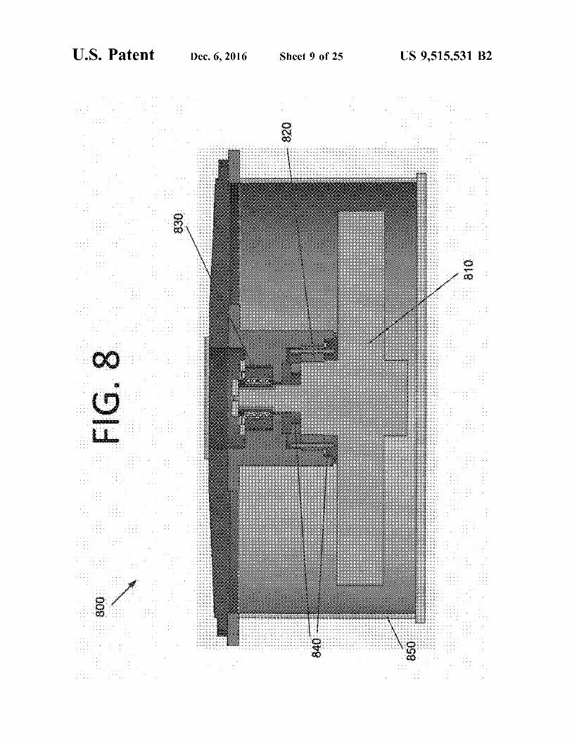
60 module bearingless motor/generator ("MG"), according toan embodiment of the present invention.FIG. 8 illustrates a side view of a high aspect ratio
("HAR") flywheel system, according to an embodiment ofthe present invention.
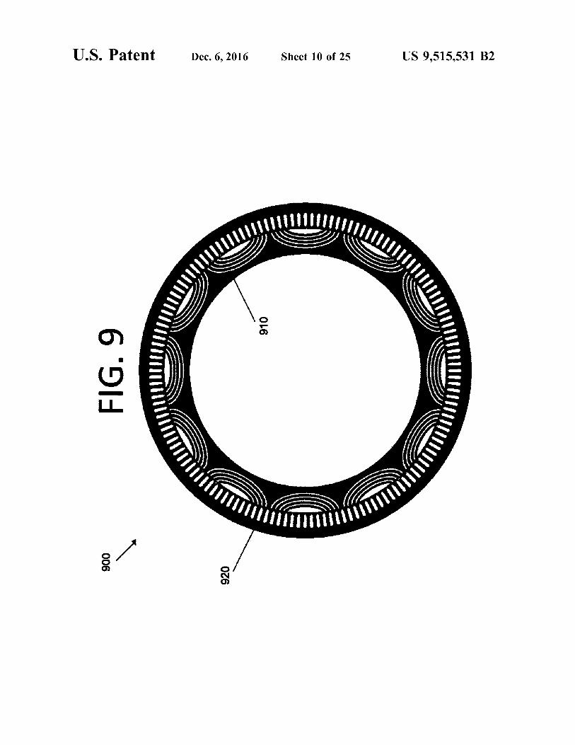
65 FIG. 9 illustrates a cross-sectional view of a HAR bear-ingless motor/generator ("MG"), according to an embodi-ment of the present invention.
US 9,515,531 B2
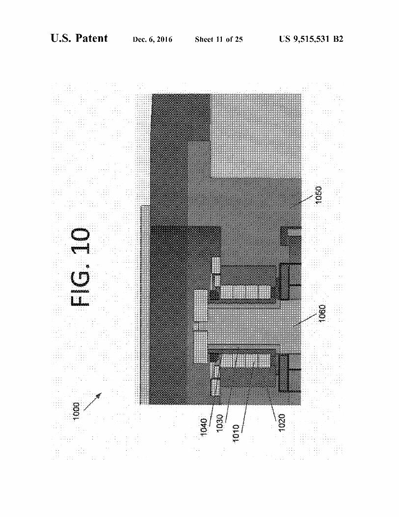
3FIG. 10 illustrates a side view of an upper portion of a
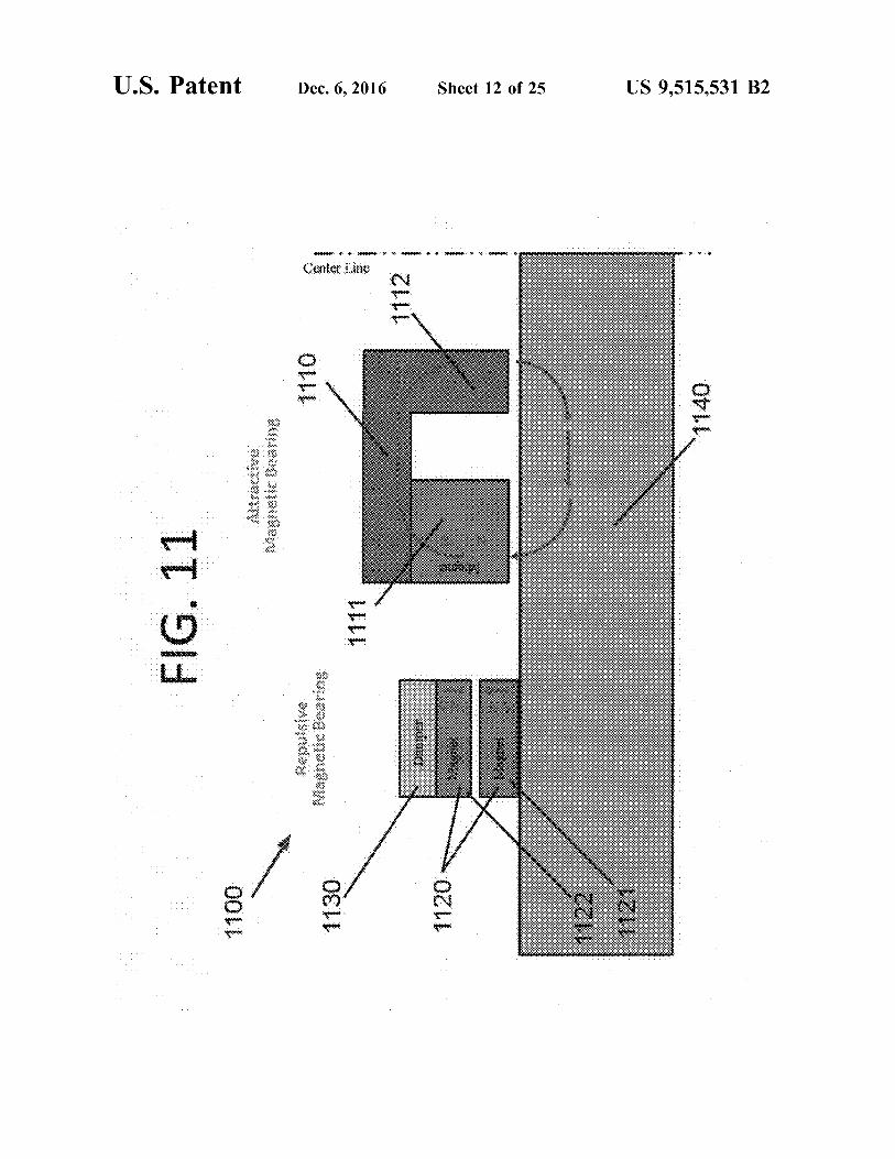
HAR, according to an embodiment of the present invention.FIG. 11 illustrates a passive MB schematic, according to
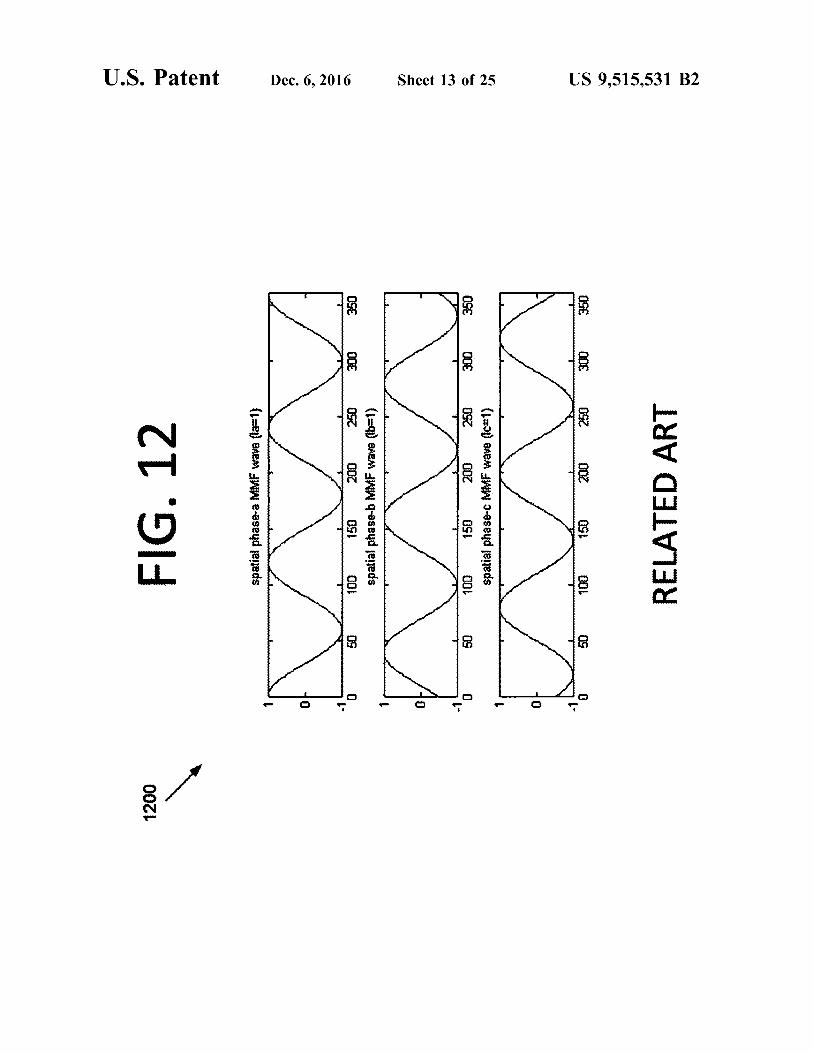
an embodiment of the present invention.FIG. 12 illustrates graphs of the spatial magnetomotive
force ("MMF") generated in a standard motor using tradi-tional windings.
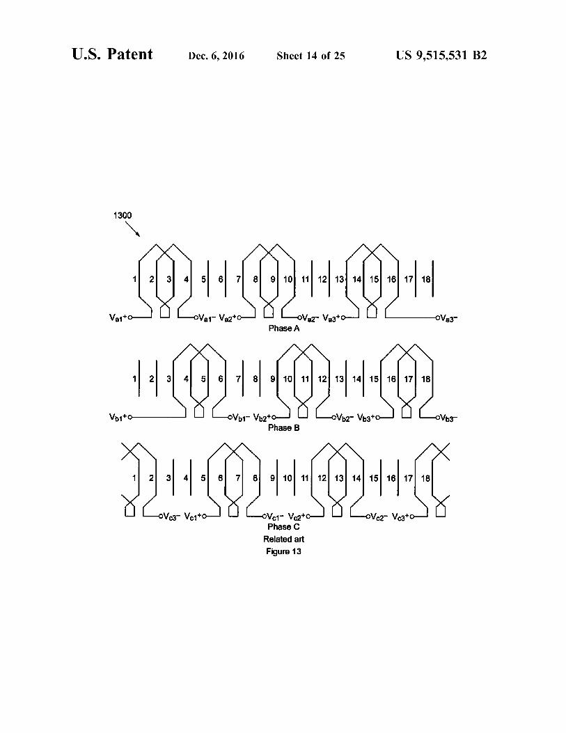
FIG. 13 illustrates a previous winding scheme for abearingless MG.
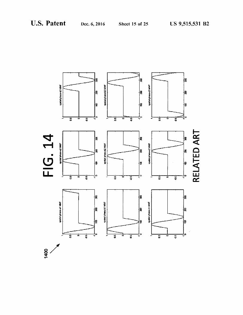
FIG. 14 illustrates graphs of spatial MMFs generated bya previous bearingless MG.
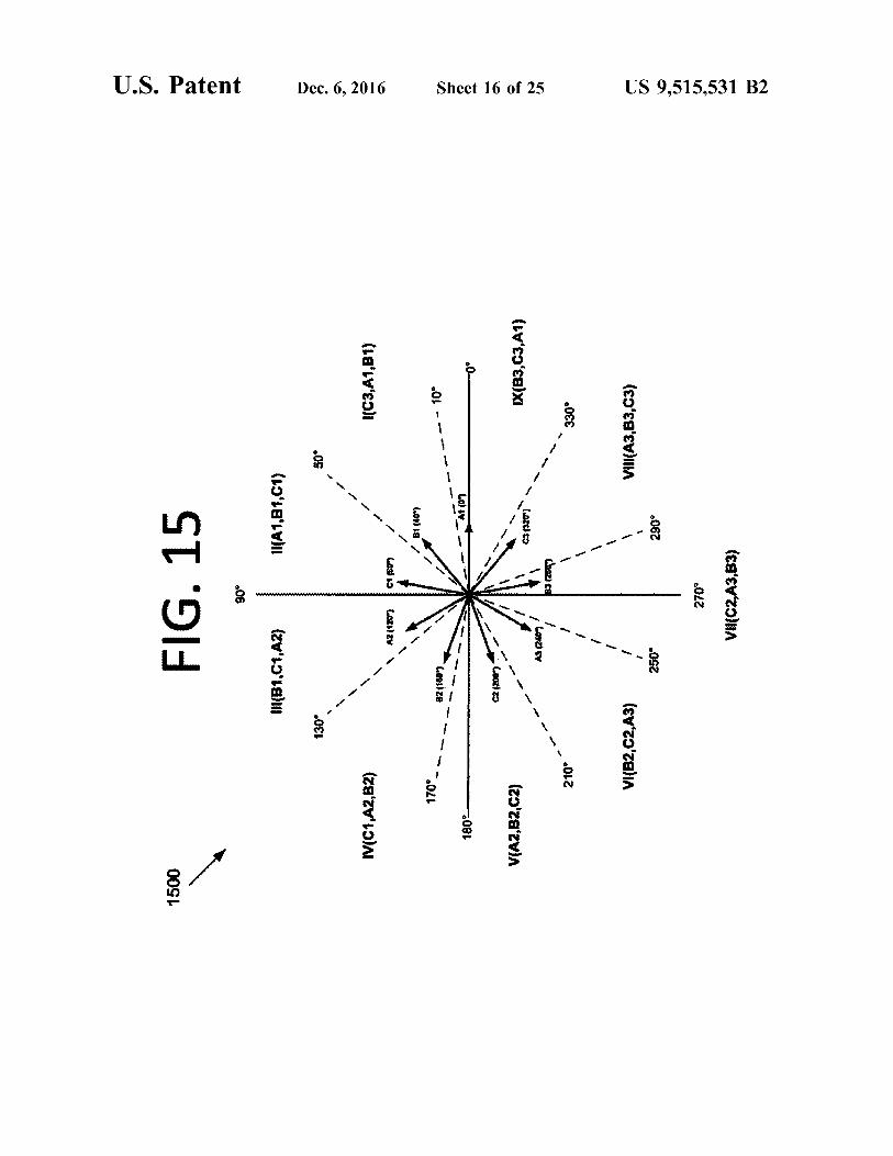
FIG. 15 illustrates an improved pole-pair reference frame,according to an embodiment of the present invention.
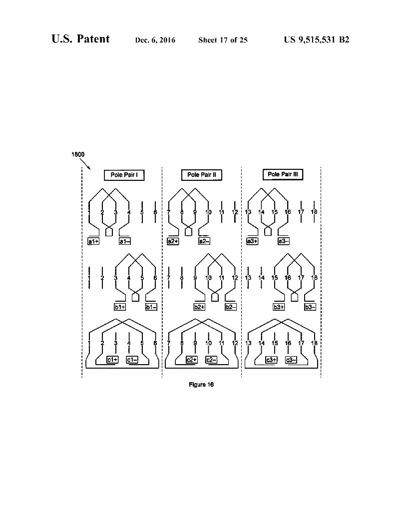
FIG. 16 illustrates a winding improvement for theimproved pole-pair reference frame scheme, according to anembodiment of the present invention.
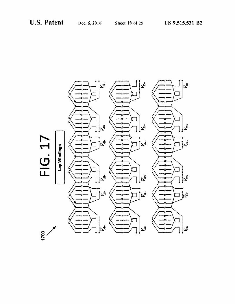
FIG. 17 illustrates a lap winding scheme, according to anembodiment of the present invention.
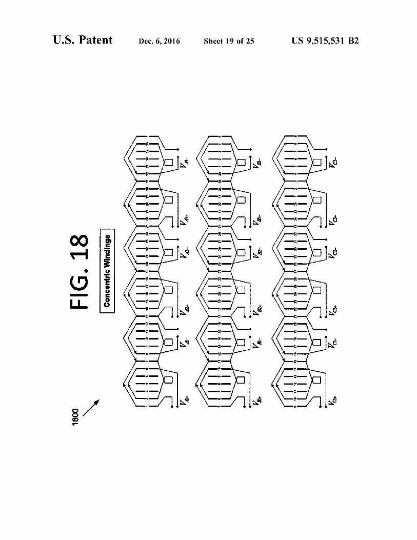
FIG. 18 illustrates a concentric winding scheme, accord-ing to an embodiment of the present invention.
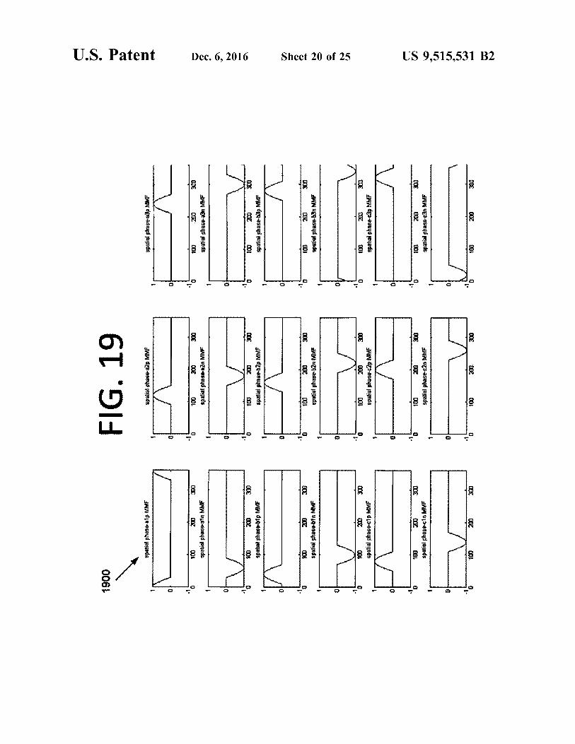
FIG. 19 illustrates IS possible spatial MMFs generated bya separate pole approach, according to an embodiment of thepresent invention.
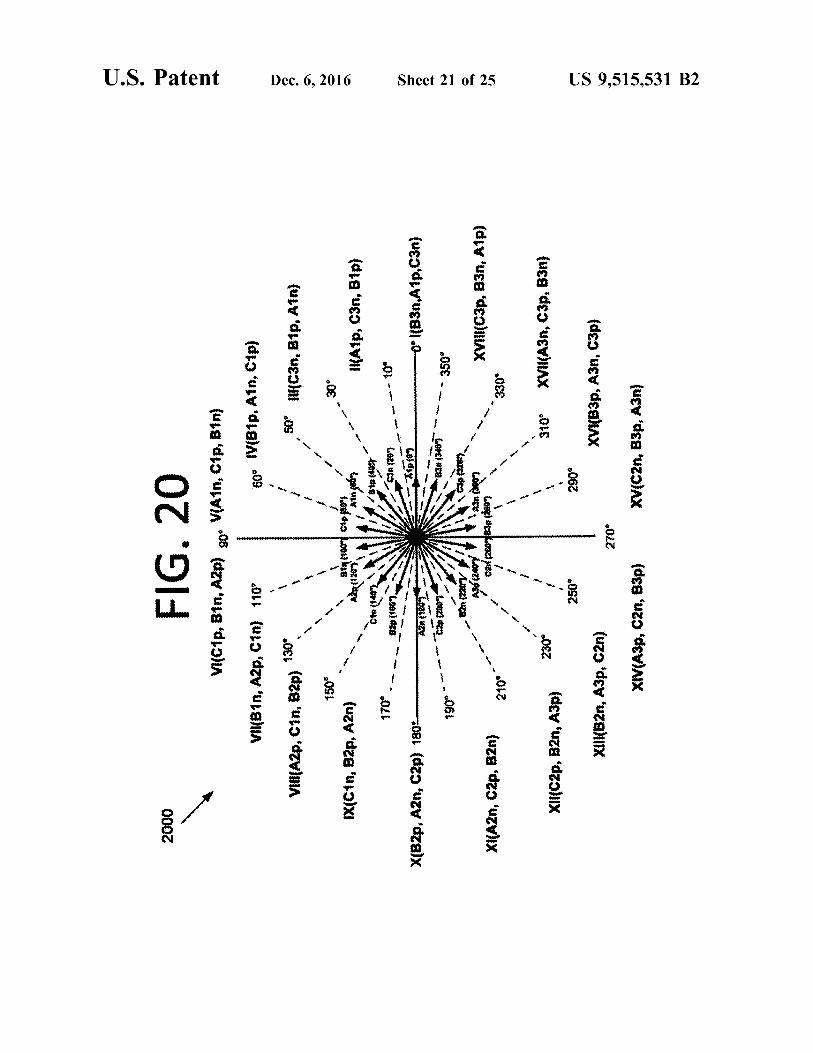
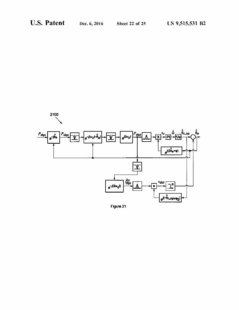
FIG. 20 illustrates a possible reference frame configura-tion for the separate pole approach, according to an embodi-ment of the present invention.FIG. 21 illustrates a logic flow diagram of rotor angle
extraction from an injected rotating vector, according to anembodiment of the present invention.
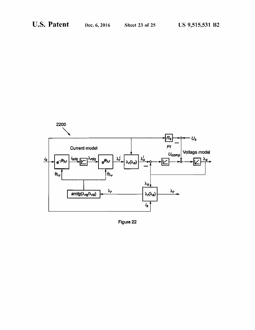
FIG. 22 illustrates a logic flow diagram of a flux observer,according to an embodiment of the present invention.
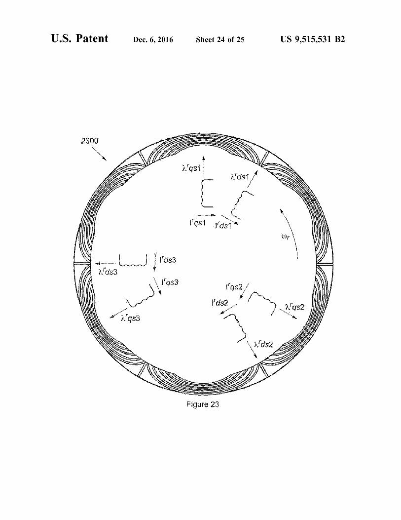
FIG. 23 illustrates a novel reference frame, according toan embodiment of the present invention.
FIG. 24 illustrates a control system for controlling andmonitoring one or more flywheel systems, according to anembodiment of the present invention.
DETAILED DESCRIPTION OF THEEMBODIMENTS
Some embodiments of the present invention pertain to anovel flywheel design, novel control and winding schemes,and/or sensorless control. The advanced technologiesinvolved, including motor, rotor and electronics designs,hold the promise to significantly increase the energy densityof high speed flywheel systems, while reducing cost. Thehigher the energy density, the lower the mass and cost of thesystem. These are important factors for terrestrial and spaceapplications. Terrestrial applications include local electricalgrid energy storage.Some embodiments of the present invention provide a
flywheel system with motor/generators ("MGs") that do nothave bearings. Such embodiments may be able to providepower for greater than three hours, and the technology maybe benchmarked as an industry driver. This is far superior toconventional run times of two to fifteen minutes. Also,individual units in some embodiments may achieve 25kilowatts ("kW"), 75 kilowatt-hours ("kW-h"), a 10 yearoperational lifetime, and a wide operating temperaturerange. Furthermore, the production cost of some embodi-ments is lower than many other energy storage technologies.
There are various benefits to local energy storage. Theseinclude providing backup power if the grid is down andproviding backup power in remote, non-grid-connectedareas. Flywheel systems may also be used to level peakversus average power usage, which is a large cost for
4utilities. This may lead to rate benefits and a reduction inpower generation and distribution infrastructure.
Flywheel energy storage itself also has various benefits.The high frequency response of flywheel systems allows for
5 the additional function of voltage regulation. Such systemsalso typically have a long operational lifetime, giving fly-wheel systems of some embodiments the potential to be acapital asset instead of an operational cost. Furthermore,flywheel systems tend to have a low environmental impact
l0 since, unlike other energy storage systems such as chemicalbatteries, flywheels generally do not contain chemicals orhazardous materials.In certain embodiments, multiple flywheel systems may
15 be grouped together (i.e., connected in series or parallel) tocreate a higher power output system. Such "flywheel farms"may have grid-level applications and could provide backuppower for higher power uses, such as for factories, largeoffices, neighborhoods, or even cities if the flywheel farm is
20 large enough. The amount of power that may be stored willdepend on the number of flywheel systems in the flywheelfarm, as well as the power storage and output capabilities ofindividual systems.One such "flywheel farm" implementation is Community
25 Energy Storage ("CES"). The maximum benefit of CES is atlocations at or near the edge of the grid, which may serve agroup of homes, for example. However, embodiments of thepresent invention may be implemented at any desired leveland are not limited to CES. The local benefits of CES
30 include renewable integration, backup power, and voltagecorrection. The grid benefits include load leveling at sub-stations, power factor correction, and ancillary services.The flywheel system of some embodiments may include
an advanced touchdown bearing design. In addition,35 advanced rotor, motor/generator ("MG"), housing, software,
power electronics, and control designs may also be includedin some embodiments. An advantage of using a MG overjust a motor is that a motor only provides rotation, whereasthe MG can convert electrical power into rotation (i.e.,
40 motor functionality) or convert mechanical rotation of therotor from an external source, such as a central rotor, intoelectrical energy (i.e., generator functionality). For practicalflywheel systems, both motoring and generation are needed.These features combine to provide a flywheel with a higher
45 energy density for grid storage applications than conven-tional systems. An all-steel rotor may be used to furtherlower costs, although any suitable material may be used.
Bearingless MGs levitate and spin the rotor (i.e., therotating portion) of the MG on a magnetic field, without the
50 use of traditional mechanical bearings (e.g., ball bearings ormagnetic bearings). Thus, bearingless MGs combine thefunctions of magnetic bearings and a motor/generator. Inflywheel applications using bearingless MGs, the centralrotor (rotating portion, or flywheel) is levitated and spun on
55 a magnetic field. A bearingless MG, or a set of bearinglessMGs, levitate and rotate the central rotor using combinedactuators. This is a complex problem since the actuatorshould be designed to work in tandem with the controlsystem, power electronics, sensors, and other systems to
60 provide levitation and spinning of the rotor without physicalcontact.In practice, some systems separate motor coils into pole-
pairs, which are each driven separately. This may allow thegeneration of six radial force vectors that are used to levitate
65 the rotor. However, these approaches leave some gaps in thespatial MMF generation, resulting in generated levitationforces that are not symmetrical.
US 9,515,531 B2
5In some embodiments, smoother force generation over
conventional systems may be provided that allows forimproved fidelity in the generation of arbitrary MMF waves.This can be implemented using two approaches: animproved pole-pair reference frame approach and a separatepole approach. The improved pole-pair reference frameapproach provides a new reference frame that takes advan-tage of improved combinations of motor spatial phases. Theseparate pole approach further subdivides motor phases intosingle poles, and may optimally combine these MMFs suchthat even greater fidelity force commands can be generated.
In order for the bearingless MG control system to operate,information on the position of the rotor in space (i.e., x, y,and z direction) and the rotational angle of the rotor isgathered and fed back to the controller. Since the rotor islevitated during operation, this position and angle informa-tion is gathered without any contact with the rotor. Inconventional systems, separate sensor subsystems are usedto gather position data and angle data. Position data forlevitated rotors (e.g., in magnetic bearings) has been gath-ered using non-contact sensors, for example, eddy currentsensors, reluctance sensors, or capacitive sensors. Rotationangle for existing motor/generators is often measured usingencoders or resolvers. Separate techniques have beendescribed for sensorless rotor position sensing, and rotorangle measurement, but no combined measurement isknown.
Certain embodiments are able to sense rotation and posi-tion information for bearingless MGs without using separatesensors. Such embodiments may provide improved dataquality (e.g., minimum noise, minimum error) at a lowercost and higher reliability. Additionally, mass and volumemay be minimized, which is desirable in many systems.Control of bearingless MGs requires accurate, non-noisyinformation of both the position of the rotor in space and theangle of the rotor's rotation, without physical contact withthe levitated rotor. Magnetic bearing systems require posi-tion information to levitate the rotor, and MGs in manyapplications require rotor angle information. In the case ofthe bearingless MG, all information on the rotor position aswell as the rotor angle must be provided, without any directcontact with the rotor. This is a complex problem, becauselateral movement of the rotor, which is allowed in bearing-less systems, will change the measured angular estimate, andvice versa. Care should be taken to correctly estimate allposition information and the angular data.
There are a number of disadvantages to using sensors togather position and angle data. Sensor systems requireadditional parts to be added to the flywheel system, whichwill increase overall flywheel system cost, introduce morepotential malfunctions, decrease system reliability, andincrease system volume and mass. These sensors can alsopick up noise, which hinders control. The noise may comefrom other electromagnetic systems (such as the MG, powerelectronics, or magnetic bearings), as well as cross-talknoise from other nearby sensors. Conventional attempts toeliminate this noise generally require additional hardware,complexity, and cost. Resolvers and encoders, which aresensors used to provide angle feedback, also have a numberof disadvantages. Acquiring the angle information withcorrect resolution and sufficient accuracy can be difficult,especially at higher speeds. Mechanical difficulties canprevent high speed operation, and these sensor types are alsosusceptible to noise, possibly from the MG itself. Thesensorless approach of some embodiments has the advan-
6tage of reducing the complexity of the system by eliminatinghardware components and their associated failure modes,volume, and mass.
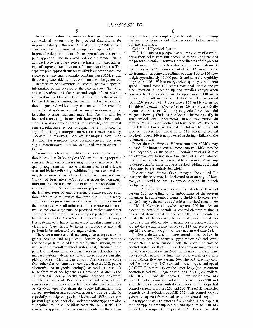
Cylindrical Flywheel System5 FIG. 1 illustrates a perspective cutaway view of a cylin-
drical flywheel system 100, according to an embodiment ofthe present invention. However, embodiments of the presentinvention are not limited to cylindrical implementations. Avacuum cylinder 110 houses a central rotor 120 in an air-free
io environment. In some embodiments, central rotor 120 mayweigh approximately 15,000 pounds and have the capabilityto provide —108 kW-h of energy when spun up to sufficientspeed. Central rotor 120 stores rotational kinetic energywhen rotation is speeding up and supplies energy when
15 central rotor 120 slows down. An upper motor 130 and alower motor 140 are positioned above and below centralrotor 120, respectively. Upper motor 130 and lower motor140 drive the rotation of central rotor 120, as well as radiallylevitate central rotor 120 using magnetic force. An axial
20 magnetic bearing 170 is used to levitate the rotor axially. Insome embodiments, upper motor 130 and lower motor 140may be MGs. Upper mechanical touchdown ("TD") bear-ings 150 and lower mechanical touchdown bearings 160provide support for central rotor 120 when cylindrical
25 flywheel system 100 is not powered or during a failure of thelevitation system.
In certain embodiments, different numbers of MGs maybe used. For instance, one or more than two MGs may beused, depending on the design. In certain situations, it may
so be advantageous to use more than two MGs. For instance,when the rotor is heavy, control of bending modes/dampingis desired, and/or more torque is desired, adding additionalMGs may be particularly beneficial.In certain embodiments, the rotor may not be vertical. For
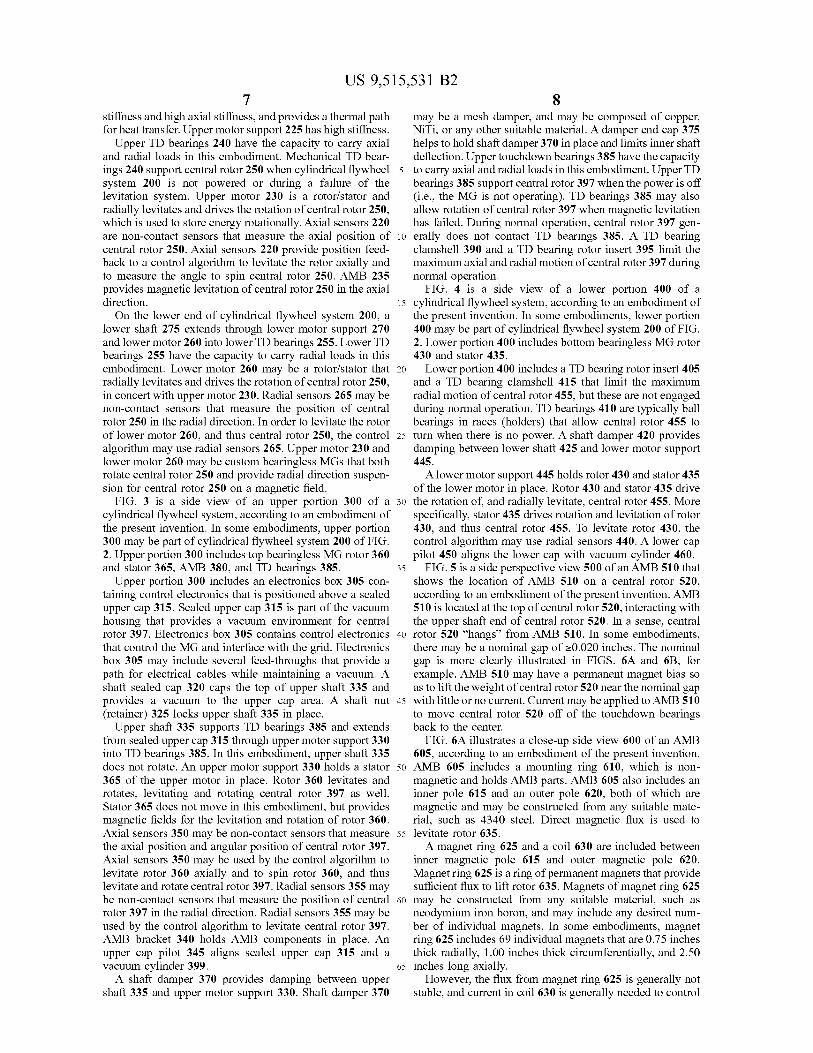
35 instance, the rotor may be horizontal or at an angle. How-ever, care should be taken to provide enough lift in suchconfigurations.FIG. 2 illustrates a side view of a cylindrical flywheel
system 200, according to an embodiment of the present40 invention. In some embodiments, cylindrical flywheel sys-
tem 200 may be the same as cylindrical flywheel system 100of FIG. 1. Cylindrical flywheel system 200 includes anelectronics box 205 containing control electronics that ispositioned above a sealed upper cap 210. In some embodi-
45 ments, the electronics may be external to cylindrical fly-wheel system 200, or placed in another location within oraround the system. Sealed upper cap 210 and sealed lowercap 280 create an airtight seal for vacuum cylinder 245.In this embodiment, software stored on controllers in
50 electronics box 205 controls upper motor 230 and lowermotor 260. In some embodiments, the controller may becontrol system 2400 of FIG. 24. The software may exist asmodules in control system 2400, for example. The softwaremay provide supervisory functions to the overall operations
55 of cylindrical flywheel system 200. The software may con-trol the outer loop (DC bus and force, torque, and speed("DC-FTS") controller) or the inner loop (motor currentcontrollers and axial magnetic bearing ("AMB") controller).The DC-FTS controller converts input sensor data into
60 current control signals to rotate and spin motors 230 and260. The motor current controller includes control loops thatcontrol current in motors 230 and 260. The AMB controllercontrols axial levitation of AMB 235. This control loop isgenerally separate from radial levitation control loops.
65 An upper shaft 215 extends from sealed upper cap 210through upper motor support 225 and upper motor 230 intoupper TD bearings 240. Upper shaft 215 has a low radial
US 9,515,531 B2
7stiffness and high axial stiffness, and provides a thermal pathfor heat transfer. Upper motor support 225 has high stiffness.
Upper TD bearings 240 have the capacity to carry axialand radial loads in this embodiment. Mechanical TD bear-ings 240 support central rotor 250 when cylindrical flywheelsystem 200 is not powered or during a failure of thelevitation system. Upper motor 230 is a rotor/stator andradially levitates and drives the rotation of central rotor 250,which is used to store energy rotationally. Axial sensors 220are non-contact sensors that measure the axial position ofcentral rotor 250. Axial sensors 220 provide position feed-back to a control algorithm to levitate the rotor axially andto measure the angle to spin central rotor 250. AMB 235provides magnetic levitation of central rotor 250 in the axialdirection.On the lower end of cylindrical flywheel system 200, a
lower shaft 275 extends through lower motor support 270and lower motor 260 into lower TD bearings 255. Lower TDbearings 255 have the capacity to carry radial loads in thisembodiment. Lower motor 260 may be a rotor/stator thatradially levitates and drives the rotation of central rotor 250,in concert with upper motor 230. Radial sensors 265 may benon-contact sensors that measure the position of centralrotor 250 in the radial direction. In order to levitate the rotorof lower motor 260, and thus central rotor 250, the controlalgorithm may use radial sensors 265. Upper motor 230 andlower motor 260 may be custom bearingless MGs that bothrotate central rotor 250 and provide radial direction suspen-sion for central rotor 250 on a magnetic field.
FIG. 3 is a side view of an upper portion 300 of acylindrical flywheel system, according to an embodiment ofthe present invention. In some embodiments, upper portion300 may be part of cylindrical flywheel system 200 of FIG.2. Upper portion 300 includes top bearingless MG rotor 360and stator 365, AMB 380, and TD bearings 385.Upper portion 300 includes an electronics box 305 con-
taining control electronics that is positioned above a sealedupper cap 315. Sealed upper cap 315 is part of the vacuumhousing that provides a vacuum environment for centralrotor 397. Electronics box 305 contains control electronicsthat control the MG and interface with the grid. Electronicsbox 305 may include several feed-throughs that provide apath for electrical cables while maintaining a vacuum. Ashaft sealed cap 320 caps the top of upper shaft 335 andprovides a vacuum to the upper cap area. A shaft nut(retainer) 325 locks upper shaft 335 in place.
Upper shaft 335 supports TD bearings 385 and extendsfrom sealed upper cap 315 through upper motor support 330into TD bearings 385. In this embodiment, upper shaft 335does not rotate. An upper motor support 330 holds a stator365 of the upper motor in place. Rotor 360 levitates androtates, levitating and rotating central rotor 397 as well.Stator 365 does not move in this embodiment, but providesmagnetic fields for the levitation and rotation of rotor 360.Axial sensors 350 may be non-contact sensors that measurethe axial position and angular position of central rotor 397.Axial sensors 350 may be used by the control algorithm tolevitate rotor 360 axially and to spin rotor 360, and thuslevitate and rotate central rotor 397. Radial sensors 355 maybe non-contact sensors that measure the position of centralrotor 397 in the radial direction. Radial sensors 355 may beused by the control algorithm to levitate central rotor 397.AMB bracket 340 holds AMB components in place. Anupper cap pilot 345 aligns sealed upper cap 315 and avacuum cylinder 399.A shaft damper 370 provides damping between upper
shaft 335 and upper motor support 330. Shaft damper 370
8may be a mesh damper, and may be composed of copper,NiTi, or any other suitable material. A damper end cap 375helps to hold shaft damper 370 in place and limits inner shaftdeflection. Upper touchdown bearings 385 have the capacity
5 to carry axial and radial loads in this embodiment. Upper TDbearings 385 support central rotor 397 when the power is off(i.e., the MG is not operating). TD bearings 385 may alsoallow rotation of central rotor 397 when magnetic levitationhas failed. During normal operation, central rotor 397 gen-
io erally does not contact TD bearings 385. A TD bearingclamshell 390 and a TD bearing rotor insert 395 limit themaximum axial and radial motion of central rotor 397 duringnormal operation.FIG. 4 is a side view of a lower portion 400 of a
15 cylindrical flywheel system, according to an embodiment ofthe present invention. In some embodiments, lower portion400 may be part of cylindrical flywheel system 200 of FIG.2. Lower portion 400 includes bottom bearingless MG rotor430 and stator 435.
20 Lower portion 400 includes a TD bearing rotor insert 405and a TD bearing clamshell 415 that limit the maximumradial motion of central rotor 455, but these are not engagedduring normal operation. TD bearings 410 are typically ballbearings in races (holders) that allow central rotor 455 to
25 turn when there is no power. A shaft damper 420 providesdamping between lower shaft 425 and lower motor support445.A lower motor support 445 holds rotor 430 and stator 435
of the lower motor in place. Rotor 430 and stator 435 drive30 the rotation of, and radially levitate, central rotor 455. More
specifically, stator 435 drives rotation and levitation of rotor430, and thus central rotor 455. To levitate rotor 430, thecontrol algorithm may use radial sensors 440. A lower cappilot 450 aligns the lower cap with vacuum cylinder 460.
35 FIG. 5 is a side perspective view 500 of an AMB 510 thatshows the location of AMB 510 on a central rotor 520,according to an embodiment of the present invention. AMB510 is located at the top of central rotor 520, interacting withthe upper shaft end of central rotor 520. In a sense, central
4o rotor 520 "hangs" from AMB 510. In some embodiments,there may be a nominal gap of 2_0.020 inches. The nominalgap is more clearly illustrated in FIGS. 6A and 613, forexample. AMB 510 may have a permanent magnet bias soas to lift the weight of central rotor 520 near the nominal gap
45 with little or no current. Current may be applied to AMB 510to move central rotor 520 off of the touchdown bearingsback to the center.FIG. 6A illustrates a close-up side view 600 of an AMB
605, according to an embodiment of the present invention.5o AMB 605 includes a mounting ring 610, which is non-
magnetic and holds AMB parts. AMB 605 also includes aninner pole 615 and an outer pole 620, both of which aremagnetic and may be constructed from any suitable mate-rial, such as 4340 steel. Direct magnetic flux is used to
55 levitate rotor 635.A magnet ring 625 and a coil 630 are included between
inner magnetic pole 615 and outer magnetic pole 620.Magnet ring 625 is a ring of permanent magnets that providesufficient flux to lift rotor 635. Magnets of magnet ring 625
60 may be constructed from any suitable material, such asneodymium iron boron, and may include any desired num-ber of individual magnets. In some embodiments, magnetring 625 includes 69 individual magnets that are 0.75 inchesthick radially, 1.00 inches thick circumferentially, and 2.50
65 inches long axially.However, the flux from magnet ring 625 is generally not
stable, and current in coil 630 is generally needed to control
US 9,515,531 B2
9levitation. Coil 630 carries current that provides adjustableflux to control levitation. In some embodiments, coil 630may be constructed from 16-gauge wire with 15 amps ofmaximum allowable current. Coil 630 may be 1.0x1.0inches with a maximum current density of 2500 amps/in.2 at15 amps, and have 167 turns. A magnetic rotor 635 ispositioned below AMB 605. Rotor 635 is the central rotor ofthe flywheel, and may be constructed from any suitablematerial, such as 15-5 PH stainless steel. Flux also flowsthrough rotor 635 and levitates rotor 635.
FIG. 6B illustrates a side view of forces acting on theAMB of FIG. 6A, according to an embodiment of thepresent invention. Magnet ring 625 sets the nominal fluxthrough inner pole 615 and outer pole 620, as well asthrough rotor 635. The force generated by this flux at anominal gap 640 is equivalent to the weight of rotor 635.Nominal gap 640 runs horizontally, and is located betweenthe flat portion of rotor 635 and the bottom sides of innerpole 615 and outer pole 620. Positive or negative currentrunning through coil 620 increases or decreases both the fluxand force, respectively.
FIG. 7 illustrates a cross-sectional view of a cylindricalmodule bearingless MG 700, according to an embodiment ofthe present invention. Bearingless MG 700 includes a rotor710, which surrounds a stator 720. Rotor 710 may have asolid design composed of high-strength steel, which mayallow rotor 710 to levitate and rotate a central rotor that hasa total kinetic energy of 104 kW-h and a normal operatingspeed of less than 12,000 rotations per minute ("rpms") insome embodiments. Bearingless MG 700 may be a synchro-nous reluctance bearingless motor.
In some embodiments, two bearingless MGs may be usedin tandem. In certain embodiments, each bearingless MGmay provide a maximum steady-state power of 31 kWacross the operating speed range. Bearingless MG 700 isunusual in that it is an inside-out motor, meaning that rotor710 (the portion that rotates) is on the outside, and stator 720(the stationary portion) is on the inside.Some embodiments may be capable of meeting perfor-
mance requirements that are superior to conventional sys-tems. For instance, some embodiments are able to operatevery safely, with little or no risk of loss of life, injury, orproperty damage. The operating life of flywheel systemsmay exceed 15 years. Some flywheel systems may providerated energy at rated power at the end of 1,000 cycles at atemperature of 25° C. Further, the service life may be greaterthan 1,000 startup/shutdown cycles.
Flywheel system storage life may be greater than fiveyears, and the flywheel system may be designed to operatewithout scheduled maintenance for at least ten years. Someembodiments may be able to operate successfully withoutcorrective maintenance for at least ten years. Also, someembodiments may be able to provide energy storage for atypical American suburb at a 25 kW/75 kW capacity levelfor clusters of 3 to 4 homes.
There is wide commercial potential for many embodi-ments of the present invention. For terrestrial implementa-tions, significant benefits could be realized for future highenergy, high speed flywheel systems. Entities that maybenefit include energy companies and U.S. governmentagencies. On a commercial grid, flywheel systems could beused for CES. Furthermore, such systems could be used forforward bases and local bases for defense applications.
High Aspect Ratio ("HAR") Flywheel SystemSome embodiments use a HAR design that may be less
expensive while providing improved performance. TheHAR design may be referred to as a disk design due to the
10relatively wide, flat shape of the rotor. Some of the improve-ments that may be realized by a HAR design includemanufacturability improvement with respect to heat treat-ment, manufacturability/assembly improvements with
5 respect to tolerance issues, a reduction in the overall partscount due to a pendulum configuration and passive AMBs.
Certain rotor designs, such as some cylindrical designs,have a practical diameter limit due to manufacturing issues.This is primarily because the heat treatment that is required
10 to guarantee performance at speed generally cannot beprovided beyond a certain size ingot of steel. Certain rotorshapes would exceed this practical limit for some intendeddesigns, providing diminished performance (e.g., top rotorspeed would be lowered). This problem could be overcome
15 by using multiple units with smaller rotors in combination tomeet required performance, but this approach would likelyalso increase cost. In order to develop a lower cost approach,a new rotor configuration that does not have heat treatlimitation issues.
20 The HAR design avoids these heat treatment issues. Withthe HAR rotor, forgings can be made with a larger size,while still guaranteeing heat treatment quality. These rotorsmay only be 12 inches thick or less in some embodiments,and heat treatment can be performed at this thickness, unlike
25 at thicker diameters used in some rotor designs.The nature of some designs, such as certain cylindrical
designs, is such that they require close tolerance control. Forexample, in some cylindrical designs, tolerances of 0.010"would need to be maintained over a ten foot length. This
30 would drive up cost because design requirements would beexacting on the manufacturer, and assembly requirementswould also be complex. Using a HAR design significantlyreduces the tolerance requirements, thus significantly reduc-ing the burden on manufacturing and assembly, and reducing
35 cost considerably.Using a single bearingless motor and a single magnetic
bearing, such as in HAR flywheel system 800 of FIG. 8,results in a "pendulum configuration", thusly named becausethe rotor in this case is not constrained at both ends, as it is
40 in the cylindrical configuration of FIGS. 1 and 2, forexample. Thus, HAR embodiments may be able to move likea pendulum. This configuration reduces the parts count byelimination of one BMG and one TD bearing, which willgenerally save cost and increase reliability.
45 Although an active MB may work for HAR designs, sucha configuration also lends itself to use of a passive MB. Thispassive approach may further reduce initial cost due toelimination of active MB parts, and also provide a moreefficient, lower power design. Additionally, a passive MB
5o reduces the requirements on the TD bearing, thereby result-ing in a lower cost TD bearing system as well. Suchembodiments, the touchdown bearing may only need tosupport radial loads, not the mass of the rotor. Additionally,the TD bearing may only need to provide radial damping,
55 rather than both radial and axial damping.FIG. 8 illustrates a side view of a HAR flywheel system
800, according to an embodiment of the present invention.As can be seen in FIG. 8, HAR flywheel system 800 has aflat, wide HAR rotor 810, a single bearingless motor 820, a
60 single touchdown bearing 830, MBs 840, and a vacuumhousing 850.FIG. 9 illustrates a cross-sectional view of a HAR BMG
900, according to an embodiment of the present invention.In some embodiments, HAR BMG 900 may be bearingless
65 motor 820 of FIG. 8. HAR BMG 900 may be a synchronousreluctance BMG. However, HAR BMG 900 is different fromthe cylindrical implementation depicted in FIG. 7 since
US 9,515,531 B211
HAR BMG 900 is not inside-out. In other words, rotor(rotating portion) 910 is on the inside, and stator (stationaryportion) 920 is on the outside.
FIG. 10 illustrates a side view of an upper portion 1000of a HAR, according to an embodiment of the presentinvention. Upper portion 1000 includes HAR TD bearings1010. HAR TD bearings 1010 have a unique bearing, mount,and damper design configuration. The touchdown bearingsystem consists of three main components: bearings 1010,spring/damper mechanism 1020, and touchdown surfaces1030 and 1040. Spring/damper mechanism 1020 is mountedin stator mount structure 1050. Spring/damper mechanism1020 provides radial spring stiffness and damping to reducethe force on central rotor 1060 and displacement of centralrotor 1060 during operation on HAR TD bearings 1010.
Spring/damper mechanism 1020 also provides a thermalpath for bearing heat transfer. Stator mount structure 1050has high stiffness. HAR TD bearings 1010 have the capacityto carry axial and radial loads in this embodiment. HAR TDbearings 1010 support central rotor 1060 when the unit is notpowered or during a failure of the levitation system. In someembodiments, HAR TD bearings will be designed such thatthe rotor drop is stable (no whirl), the rotor displacementsare low (no contact with the motor(s)), and the forces onHAR TD bearings 1010 are reasonable.A wire mesh damper may be part of spring/damper 1020.
Copper, stainless steel, or other suitable materials may beused. Spring/damper 1020 should minimize forces on cen-tral rotor 1060 while limiting the maximum displacement ofcentral rotor 1060. The target for some embodiments was tofind a spring/damper with a stiffness of 10,000 pounds perinch and damping of 100 lb-s/in. for low frequency modes.
Active MBs generally perform well. However, their usegenerally increases the parts count. This is because sensors,power electronics, controller analog-to-digital ("A/D") con-verters and digital-to-analog ("D/A") converters, and soft-ware are all generally needed to make active MBs work. Atcontroller input, the analog signals from the sensors areconverted using A/D converters to digital signals the con-troller can interpret. Conversely, the D/A converters convertthe controller digital signal to analog to interface with thebearing power electronics. The A/D converters and D/Aconverters are resources that might not need to be provided,saving cost, reducing complexity, reducing possible failuremodes, etc. Accordingly, some flywheel system embodi-ments use a passive MB design that lowers parts count andincreases reliability.
Passive MB embodiments typically use permanent mag-nets ("PMs") instead of electromagnets. This simplifies thedesign and reduces the parts count. Since the PMs providethe flux without the need for electric current (unlike activeMBs), this approach will also generally save power, makingthe system more efficient. The passive MB is generallyseparated into two sections an attractive magnetic bearingand a repulsive magnetic bearing (see, for example, attrac-tive magnetic bearing 1110 and repulsive magnetic bearing1120 of FIG. 11).
FIG. 11 illustrates a passive MB schematic, according toan embodiment of the present invention. Attractive magneticbearing 1110 includes a permanent magnet ring 1111 and aniron flux path 1112, and attractive magnetic bearing 1110interacts with central rotor 1140. Repulsive magnetic bear-ing 1120 includes two permanent magnet rings 1121 and1122 oriented in an opposing configuration. Lower perma-nent magnet ring 1121 is mounted on central rotor 1140.Upper permanent magnet ring 1122 may be mounted in adamper structure 1130.
12The combination of the forces and stiffnesses of attractive
magnetic bearing 1110 and repulsive magnetic bearing 1120,and the weight of rotor 1140, create a passive axial levitationsystem in which an air gap is present between attractive
5 magnetic bearing 1110 and central rotor 1140, as well asbetween magnetic rings 1121 and 1122. The componentscreate a neutral point in space with zero net force that centralrotor 1140 moves to when displaced. An axial restoring forceis provided when central rotor 1140 moves away from the
to neutral point. Repulsive magnetic bearing 1120 may createa small radial destabilizing force that will be counteracted bythe bearingless motor in some embodiments. Additionally,repulsive magnetic bearing 1120 provides a restoring torque
15 to central rotor 1140 if the centerline is tilted through anangle like a pendulum. Magnetic ring 1122 of repulsivemagnetic bearing 1120 may be mounted on mechanicaldamper 1130 that provides damping to reduce the amplitudeof any tilting motion mentioned above.
20 Winding and Control SchemesIn bearingless MGs such as those discussed above, the
rotor is completely levitated and spun on a magnetic field. Itis generally desirable to use schemes for winding andcontrolling bearingless MGs that provide force generation
25 that is as smooth as possible. Some embodiments employ animproved pole-pair reference frame approach or a separatepole approach.The improved pole-pair reference frame approach pro-
vides a new reference frame that takes advantage of30 improved combinations of motor spatial phases. The per-
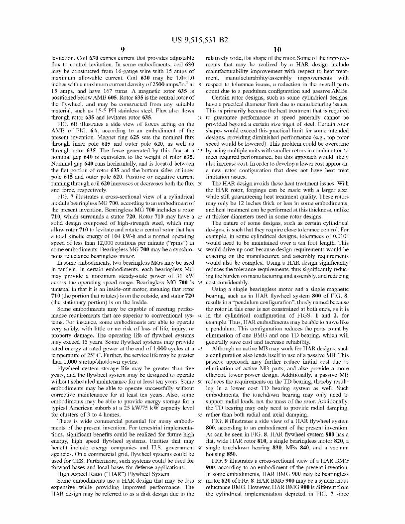
formance improvements provided by some embodimentsmay be explained in terms of generated spatial MMFs.Graphs 1200 of the spatial MMF generated in a standardmotor, using traditional windings, are shown in FIG. 12. In
35 this case, Ia, lb, and Ic are set to 1 amp (and, for simplicity,the total equivalent turns is also 1). The resulting MMF isplotted versus mechanical angle.
Note that in the standard motor, there is no net MMF. Inother words, all three MMFs cancel each other out, leaving
4o no net force. This is of no use in levitating the rotor. In orderto generate a net levitation force, the motor coils should beseparated.In some bearingless MGs, the pole pairs are driven
separately. FIG. 13 illustrates a previous winding scheme45 1300 for a bearingless MG. Graphs 1400 of the spatial
MMFs generated in a bearingless MG are shown in FIG. 14.Note that these MMFs can be arbitrarily controlled. Thisallows generation of an imbalanced MMF, and thus creationof radial levitation forces.
50 It is possible to make improvements over existing bear-ingless MGs without making motor winding changes. Notethat in previous systems, al, bl, and cl are controlledtogether, and likewise a2-c2 are controlled together and a3-c3 are controlled together. This approach groups the force
55 by motor phases (stator windings). Thus, the control islinked to the stator, not the rotor. However, this leaves somegaps in the spatial force generation capability.
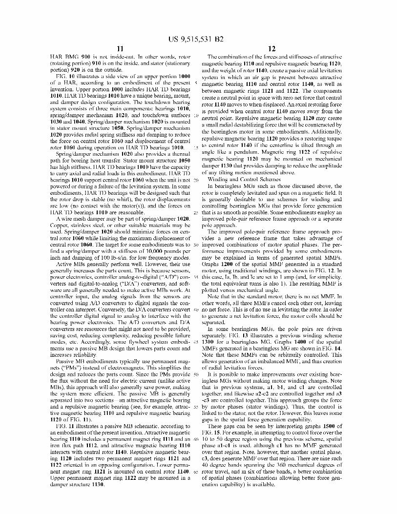
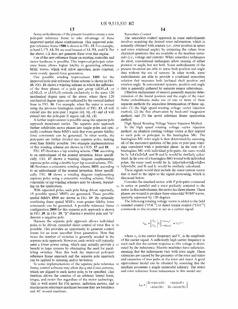
These gaps can be seen by interpreting graphs 1500 ofFIG. 15. For example, in attempting to control force over the
60 10 to 50 degree region using the previous scheme, spatialphase al-cl is used, although cl has no MMF generatedover that region. Note, however, that another spatial phase,c3, does generate MMF over that region. There are nine such40 degree bands spanning the 360 mechanical degrees of
65 rotor travel, and in six of these bands, a better combinationof spatial phases (combinations allowing better force gen-eration capability) is available.
US 9,515,531 B2
13Some embodiments of the present invention create a new
pole-pair reference frame to take advantage of theseimproved spatial phase combinations. This improved pole-pair reference frame 1500 is shown in FIG. 15. For example,at band I, C3, Al, Bl are used instead ofA1, Bl, and Cl. Perthe above, Cl does not generate force over this region.Use of the new reference frame on existing controller and
motor hardware is possible. This improved pole-pair refer-ence frame allows higher fidelity in generating arbitraryMMF waves, which will allow smoother, more constant,more evenly spaced force generation.One possible winding improvement 1600 for the
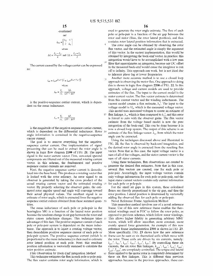
improved pole-pair reference frame scheme is shown in FIG.16. FIG. 16 shows a winding scheme in which the influenceof the three phases of a pole pair group (al,bl,cl, ora2,b2,c2, or a3,b3,c3) extends exclusively to the same 120mechanical degree span of the stator, where these 120mechanical degree spans are indicated by the vertical dashedlines in FIG. 16. For example, when the stator is woundusing the previous bearingless method of FIG. 13, c3 willextend into the pole-pair I region (al, bl, cl) and cl willextend into the pole-pair II region (a2, b2, c2).A further improvement is possible using the separate pole
approach mentioned earlier. The separate pole approachfurther subdivides motor phases into single poles and opti-mally combines these MMFs such that even greater fidelityforce commands can be generated. In other words, thepole-pairs are further divided into separate poles, makingeven finer fidelity possible. Two example implementationsof this winding scheme are shown in FIGS. 17 and 18.
FIG. 17 illustrates a lap winding scheme 1700, accordingto an embodiment of the present invention. More specifi-cally, FIG. 17 shows a winding diagram implementingseparate poles using a double layer lap wound scheme. FIG.18 illustrates a concentric winding scheme 1800, accordingto an embodiment of the present invention. More specifi-cally, FIG. 18 shows a winding diagram implementingseparate poles using a concentric winding scheme. Eitherconcentric or lap winding schemes may be chosen, depend-ing on the application.
With separated poles, each pole being driven separately,1S possible spatial MMFs are generated. These possiblespatial MMFs 1900 are shown in FIG. 19. By optimallycombining these spatial MMFs, even greater fidelity forcecommands can be generated. A possible reference frameconfiguration 2000 for this separate pole approach is shownin FIG. 20. In FIG. 20, "p" denotes a positive pole and "n"denotes a negative pole.
Because the separate pole approach allows individualpoles to be driven, extended direct control of rotor flux ispossible. This provides an opportunity to generate controlforces for an even smoother force generation. Note thattwice the number of switches is generally needed in theseparate pole approach. However, each switch will typicallyneed a lower power rating, which may actually provide abenefit in large systems by eliminating the need for paral-leling switches. Note that both the improved pole-pairreference frame approach and the separate pole approachcan be applied to spinning and/or levitation.
In some implementations of the separate pole referenceframe, control software may allow the q and d axis currents,which are aligned to each motor pole, to be specified. Thisfreedom allows the creation of an arbitrary lateral force,torque, and motor flux regardless of the motor technology.This is well suited for PM motors, induction motors, andsynchronous reluctance machines because they are brushlessand AC wound machines.
14Sensorless ControlThe sensorless control approach in some embodiments
involves acquiring the desired rotor information, which isnormally obtained with sensors (i.e., rotor position in space
5 and rotor rotational angle), by extracting the values fromelectrical quantities that are available at the machine termi-nals (i.e., voltage and current). While sensorless techniquesdo exist, conventional techniques allow sensing of eitherposition or angle, but not both. Some embodiments of the
to present invention are able to sense both position and angledata without the use of sensors. In other words, someembodiments are able to provide a combined sensorlesssolution that measures both levitated shaft position androtation angle. In conventional systems, position and angle
15 data is generally gathered by separate sensor subsystems.Effective replacement of sensors generally requires deter-
mination of the lateral position and the angle of the rotor.Some embodiments make use of one or more of threeseparate methods for sensorless determination of these sig-
2o nals: (1) the high speed rotating voltage vector injectionmethod; (2) the flux observation by back-emf integrationmethod; and (3) the novel reference frame applicationmethod.High Speed Rotating Voltage Vector Injection Method
25 In the high speed rotating voltage vector injectionmethod, an identical rotating voltage vector is first appliedto each pole or pole-pair in the bearingless MG. Thebearingless MG rotor angle is then determined by summingall of the measured qualities of the pole or pole-pair wind-
30 ings associated with a particular phase. In the case of abearingless MG with individual pole-pairs, the sums wouldbe Ia=Ia1+Ia2+Ia3, and lb and Ic would be similarly calcu-lated. In the case of a bearingless MG wound with individualpoles, the sums used would be Ia=Ialp+Ialn+Ia2p+Ia2n+
35 Ia3p+Ia3n, and lb and Ic would be similarly calculated.These signals would then include the stator current vector
that is used as the input to the signal processing, which isdiscussed below.
Consider the standard motor, with P pole-pairs connected
40 in series or parallel and a rotor perfectly centered to thestator. In this embodiment, the motor has three phases. Thesephases are wound to produce three sinusoidal WIMP waves,spatially separated by 120 degrees.The following rotating voltage vector is added to the field
45 oriented control ("FOC") or direct torque control ("DTC")commands to the inverter to act as a carrier signal:
V m,tV Rc
_ VL~ COS &),t
VLF®rl~r
50 Vq, —sinm't
where w, is the carrier frequency and V, is the amplitudeof the carrier signal. A sufficiently high carrier frequency is
55 used such that the current response to this voltage is domi-nated by the inductance. Electric machines have saliencies,meaning that the inductances vary with rotor angle. Thesesaliencies are caused by the geometry of the rotor and statorand saturation of iron paths in the rotor and stator. A good
60 approximate model can be obtained by assuming that themachine possesses a single sinusoidal saliency. The statorand rotor reference frame inductances in this model are:
65 EL+OLcos(200) —OLsin(2Ba)
— —OLsin(200) EL—OLcos(2Be) 1
as:
US 9,515,531 B2
15-continued
and
4q—[Ld 0
0 L'
where
AL = Ld — L9
and EL = Ld + L9
2 2
The current caused by the voltage carrier can be expressed
= l 2) + [_,j("°t+20 z)
where
V, ELW EL2 —
OL2
is the positive-sequence carrier current, which is depen-dent on the mean inductance.
V, ALW EL2 —
OL2
is the magnitude of the negative-sequence carrier current,which is dependent on the differential inductance. Rotorangle information is contained in the negative-sequencecarrier current.The goal is to remove everything but the negative-
sequence carrier current. One implementation of signalprocessing that can be used to extract the rotor angle isshown in logic flow diagram 2100 of FIG. 21. The inputsignal is the stator current vector. First, unwanted spectralcomponents are filtered out of the measured rotating currentvector. In this scheme, the fundamental and positivesequence carrier currents are removed.
Next, the negative sequence carrier current is demodu-lated into the base band. This produces a rotating vector thatis locked with the rotor saliency. An error signal to anobserver is generated by taking the cross product of theactual rotating current vector and the estimated rotatingvector. By properly selecting the observer gains, the esti-mated rotor angular speed and angle will converge towardtheir actual physical values. The resultant signal is anestimate of rotor angle, which is extracted from the negativesequence carrier current obtained from these summed quan-tities.The mean inductance of each pole or pole-pair in the
bearingless MG is a function of the lateral rotor positionbecause the resultant change in air gap between the rotor andstator causes inductance changes. This technique takesadvantage of this fact. The positive sequence current of eachpole or pole-pair system is dependent on the mean induc-tance. The approach is to inject a rotating voltage vector,then demodulate positive sequence current of each pole orpole-pair system. The positive sequence current (which isproportional to the mean inductance) is then used to estimaterotor lateral position at each pole. Next, this resultantposition information is vectorially summed to calculate therotor position estimate.
Flux Observation by Back-Emf Integration MethodThis technique estimates the flux in each pole or pole-pair.
The flux vector contains rotor angle information, which is
16used to generate the rotor angle estimate. The flux of eachpole or pole-pair is a function of the air gap between therotor and stator (thus, the rotor lateral position), and thuscontains rotor lateral position information that is extracted.
5 The rotor angle can be obtained by observing the rotorflux vector, and the estimated angle is simply the argumentof this vector. In the easiest implementation, this would beobtained by integrating the back-emf vector. In practice, thisintegration would have to be accomplished with a low pass
10 filter that approximates an integrator, because any DC offsetin the measured back-emf would cause the integrator to runoff to infinity. This approach can work, but is not ideal dueto inherent phase lag at lower frequencies.
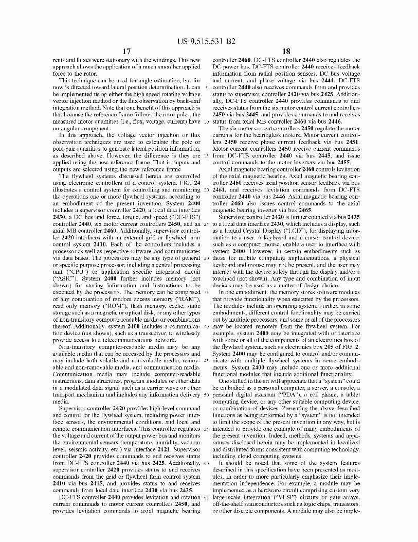
15 Another more accurate method is to use a closed loopapproach to observing the motor flux. One approach to doingthis is shown in logic flow diagram 2200 of FIG. 22. In thisapproach, voltage and current models are used to provideestimates of the flux. The input to the current model is the
20 stator current vector. The flux vector estimate is determinedfrom this current vector and the winding inductances. Thecurrent model creates a flux estimate, X,. The input to thevoltage model is Us, which is the measured voltage vector.This model uses measured voltages to create an estimate of
25 flux linkage, X,, which is then compared to X,1, and this erroris forced to zero with the observer gains. The flux vectorestimate from the voltage based model is now the pureintegration of the back-emf. This can be done because it isnow a closed loop system. The output of this scheme is an
30 estimate of the flux linkage vector, X,, from which the rotorangle can be extracted.
Using the techniques discussed above and illustrated inFIG. 22, the flux is observed by back-emf integration, and
35 the desired rotor angle is extracted from the resulting fluxvector. Note that in this case, the input voltage vector is asum of all of the voltages, and the stator current vector is thesum of all stator currents.
Using these techniques, flux observations are created to
40 generate the desired flux estimates. Note that in this case,several flux vectors are created, one for each pole orpole-pair. Accordingly, the input voltage vectors containonly voltage information for each pole or pole-pair, and theinput stator current vectors contain only current information
45 for each pole or pole-pair.For the small air gaps in this system, these calculated
fluxes are directly proportional to the air gap, and thus therotor position. Lateral position is determined by vectoriallyadding the observed flux for each pole or pole-pair.
50 Novel Reference Frame Application MethodThis sensorless method involves use of a novel reference
frame. Use of this new reference frame enables the theo-retical windings used in FOC to follow the rotor poles, asopposed to previous schemes, which follow stator windings.
55 This allows higher fidelity in generating arbitrary MMFwaves, which will allow smoother, more constant, moreevenly spaced force generation. An example of this newreference frame implementation 2300 is shown in FIG. 23.More specifically, FIG. 23 shows how the new reference
60 frame can be seen as six theoretical coils which move withthe rotor. These coils are driven by six currents, namely:Igsr", Idsr", Igs2", Ias2", Igs3", Ids3". By controlling these sixcurrents, the six rotor flux linkages, X.,1" lasr
" lgs2"
lase"
Igs3", Ids3", are completely controlled. The torque and lateral65 force applied to the motor rotor is completely determined by
these six flux linkages. This is different than previousapproaches because in the previous approaches, these cur-
US 9,515,531 B2
17rents and fluxes were stationary with the windings. This newapproach allows the application of a much smoother appliedforce to the rotor.
This technique can be used for angle estimation, but fornow is directed toward lateral position determination. It canbe implemented using either the high speed rotating voltagevector injection method or the flux observation by back-emfintegration method. Note that one benefit of this approach isthat because the reference frame follows the rotor poles, themeasured motor quantities (i.e., flux, voltage, current) haveno angular component.
In this approach, the voltage vector injection or fluxobservation techniques are used to calculate the pole orpole-pair quantities to generate lateral position information,as described above. However, the difference is they areapplied using the new reference frame. That is, inputs andoutputs are selected using the new reference frame.The flywheel systems discussed herein are controlled
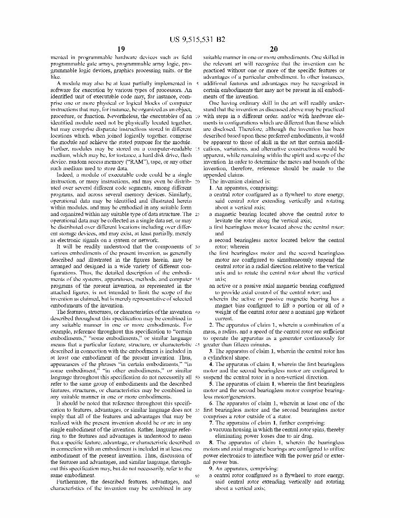
using electronic controllers of a control system. FIG. 24illustrates a control system for controlling and monitoringthe operations one or more flywheel systems, according toan embodiment of the present invention. System 2400includes a supervisor controller 2420, a local data interface2430, a DC bus and force, torque, and speed ("DC-FTS")controller 2440, six motor current controllers 2450, and anaxial MB controller 2460. Additionally, supervisor control-ler 2420 interfaces with an external grid or flywheel farmcontrol system 2410. Each of the controllers includes aprocessor as well as respective software, and communicatesvia data buses. The processors may be any type of generalor specific purpose processor, including a central processingunit ("CPU") or application specific integrated circuit("ASIC"). System 2400 further includes memory (notshown) for storing information and instructions to beexecuted by the processors. The memory can be comprisedof any combination of random access memory ("RAM"),read only memory ("ROM"), flash memory, cache, staticstorage such as a magnetic or optical disk, or any other typesof non-transitory computer-readable media or combinationsthereof. Additionally, system 2400 includes a communica-tion device (not shown), such as a transceiver, to wirelesslyprovide access to a telecommunications network.Non-transitory computer-readable media may be any
available media that can be accessed by the processors andmay include both volatile and non-volatile media, remov-able and non-removable media, and communication media.Communication media may include computer-readableinstructions, data structures, program modules or other datain a modulated data signal such as a carrier wave or othertransport mechanism and includes any information deliverymedia.
Supervisor controller 2420 provides high-level commandand control for the flywheel system, including power inter-face sensors, the environmental conditions, and local andremote communication interfaces. This controller regulatesthe voltage and current of the output power bus and monitorsthe environmental sensors (temperature, humidity, vacuumlevel, seismic activity, etc.) via interface 2421. Supervisorcontroller 2420 provides commands to and receives statusfrom DC-FTS controller 2440 via bus 2425. Additionally,supervisor controller 2420 provides status to and receivescommands from the grid or flywheel farm control system2410 via bus 2415, and provides status to and receivescommands from local data interface 2430 via bus 2435.DC-FTS controller 2440 provides levitation and rotation
current commands to motor current controllers 2450, andprovides levitation commands to axial magnetic bearing
18controller 2460. DC-FTS controller 2440 also regulates theDC power bus. DC-FTS controller 2440 receives feedbackinformation from radial position sensors, DC bus voltageand current, and phase voltage via bus 2441. DC-FTS
5 controller 2440 also receives commands from and providesstatus to supervisor controller 2420 via bus 2425. Addition-ally, DC-FTS controller 2440 provides commands to andreceives status from the six motor control current controllers2450 via bus 2445, and provides commands to and receives
io status from axial MB controller 2460 via bus 2446.The six motor current controllers 2450 regulate the motor
currents for the bearingless motors. Motor current control-lers 2450 receive phase current feedback via bus 2451.Motor current controllers 2450 receive current commands
15 from DC-FTS controller 2440 via bus 2445, and issuecontrol commands to the motor inverters via bus 2455.
Axial magnetic bearing controller 2460 controls levitationof the axial magnetic bearing. Axial magnetic bearing con-troller 2460 receives axial position sensor feedback via bus
20 2461, and receives levitation commands from DC-FTScontroller 2440 via bus 2446. Axial magnetic bearing con-troller 2460 also issues control commands to the axialmagnetic bearing inverter via bus 2465.
Supervisor controller 2420 is further coupled via bus 243525 to a local data interface 2430, which includes a display, such
as a Liquid Crystal Display ("LCD"), for displaying infor-mation to a user. A keyboard and a cursor control device,such as a computer mouse, enable a user to interface withsystem 2400. However, in certain embodiments such as
so those for mobile computing implementations, a physicalkeyboard and mouse may not be present, and the user mayinteract with the device solely through the display and/or atouchpad (not shown). Any type and combination of inputdevices may be used as a matter of design choice.
35 In one embodiment, the memory stores software modulesthat provide functionality when executed by the processors.The modules include an operating system. Further, in someembodiments, different control functionality may be carriedout by multiple processors, and some or all of the processors
40 may be located remotely from the flywheel system. Forexample, system 2400 may be integrated with or interfacewith some or all of the components of an electronics box ofthe flywheel system, such as electronics box 205 of FIG. 2.System 2400 may be configured to control and/or commu-
45 nicate with multiple flywheel systems in some embodi-ments. System 2400 may include one or more additionalfunctional modules that include additional functionality.One skilled in the art will appreciate that a "system" could
be embodied as a personal computer, a server, a console, a50 personal digital assistant ("PDA"), a cell phone, a tablet
computing device, or any other suitable computing device,or combination of devices. Presenting the above-describedfunctions as being performed by a "system" is not intendedto limit the scope of the present invention in any way, but is
55 intended to provide one example of many embodiments ofthe present invention. Indeed, methods, systems and appa-ratuses disclosed herein may be implemented in localizedand distributed forms consistent with computing technology,including cloud computing systems.
60 It should be noted that some of the system featuresdescribed in this specification have been presented as mod-ules, in order to more particularly emphasize their imple-mentation independence. For example, a module may beimplemented as a hardware circuit comprising custom very
65 large scale integration ("VLSI") circuits or gate arrays,off-the-shelf semiconductors such as logic chips, transistors,or other discrete components. A module may also be imple-
US 9,515,531 B2
19mented in programmable hardware devices such as fieldprogrammable gate arrays, programmable array logic, pro-grammable logic devices, graphics processing units, or thelike.A module may also be at least partially implemented in 5
software for execution by various types of processors. Anidentified unit of executable code may, for instance, com-prise one or more physical or logical blocks of computerinstructions that may, for instance, be organized as an object,procedure, or function. Nevertheless, the executables of an ioidentified module need not be physically located together,but may comprise disparate instructions stored in differentlocations which, when joined logically together, comprisethe module and achieve the stated purpose for the module.Further, modules may be stored on a computer-readable 15medium, which may be, for instance, a hard disk drive, flashdevice, random access memory ("RAM"), tape, or any othersuch medium used to store data.
Indeed, a module of executable code could be a singleinstruction, or many instructions, and may even be distrib- 20uted over several different code segments, among differentprograms, and across several memory devices. Similarly,operational data may be identified and illustrated hereinwithin modules, and may be embodied in any suitable formand organized within any suitable type of data structure. The 25operational data may be collected as a single data set, or maybe distributed over different locations including over differ-ent storage devices, and may exist, at least partially, merelyas electronic signals on a system or network.
It will be readily understood that the components of 30various embodiments of the present invention, as generallydescribed and illustrated in the figures herein, may bearranged and designed in a wide variety of different con-figurations. Thus, the detailed description of the embodi-ments of the systems, apparatuses, methods, and computer 35programs of the present invention, as represented in theattached figures, is not intended to limit the scope of theinvention as claimed, but is merely representative of selectedembodiments of the invention.The features, structures, or characteristics of the invention 40
described throughout this specification may be combined inany suitable manner in one or more embodiments. Forexample, reference throughout this specification to "certainembodiments," "some embodiments," or similar languagemeans that a particular feature, structure, or characteristic 45described in connection with the embodiment is included inat least one embodiment of the present invention. Thus,appearances of the phrases "in certain embodiments," "insome embodiment," "in other embodiments," or similarlanguage throughout this specification do not necessarily all 50refer to the same group of embodiments and the describedfeatures, structures, or characteristics may be combined inany suitable manner in one or more embodiments.
It should be noted that reference throughout this specifi-cation to features, advantages, or similar language does not 55imply that all of the features and advantages that may berealized with the present invention should be or are in anysingle embodiment of the invention. Rather, language refer-ring to the features and advantages is understood to meanthat a specific feature, advantage, or characteristic described 60in connection with an embodiment is included in at least oneembodiment of the present invention. Thus, discussion ofthe features and advantages, and similar language, through-out this specification may, but do not necessarily, refer to thesame embodiment. 65
Furthermore, the described features, advantages, andcharacteristics of the invention may be combined in any
20suitable manner in one or more embodiments. One skilled inthe relevant art will recognize that the invention can bepracticed without one or more of the specific features oradvantages of a particular embodiment. In other instances,additional features and advantages may be recognized incertain embodiments that may not be present in all embodi-ments of the invention.One having ordinary skill in the art will readily under-
stand that the invention as discussed above may be practicedwith steps in a different order, and/or with hardware ele-ments in configurations which are different than those whichare disclosed. Therefore, although the invention has beendescribed based upon these preferred embodiments, it wouldbe apparent to those of skill in the art that certain modifi-cations, variations, and alternative constructions would beapparent, while remaining within the spirit and scope of theinvention. In order to determine the metes and bounds of theinvention, therefore, reference should be made to theappended claims.The invention claimed is:1. An apparatus, comprising:a central rotor configured as a flywheel to store energy,
said central rotor extending vertically and rotatingabout a vertical axis;
a magnetic bearing located above the central rotor tolevitate the rotor along the vertical axis;
a first bearingless motor located above the central rotor;and
a second bearingless motor located below the centralrotor; wherein
the first bearingless motor and the second bearinglessmotor are configured to simultaneously suspend thecentral rotor in a radial direction relative to the verticalaxis and to rotate the central rotor about the verticalaxis;
an active or a passive axial magnetic bearing configuredto provide axial control of the central rotor; and
wherein the active or passive magnetic bearing has amagnet bias configured to lift a portion or all of aweight of the central rotor near a nominal gap withoutcurrent.
2. The apparatus of claim 1, wherein a combination of amass, a radius, and a speed of the central rotor are sufficientto operate the apparatus as a generator continuously forgreater than fifteen minutes.
3. The apparatus of claim 1, wherein the central rotor hasa cylindrical shape.
4. The apparatus of claim 1, wherein the first bearinglessmotor and the second bearingless motor are configured tosuspend the central rotor in a non-vertical direction.
5. The apparatus of claim 1, wherein the first bearinglessmotor and the second bearingless motor comprise bearing-less motor/generators.
6. The apparatus of claim 1, wherein at least one of thefirst bearingless motor and the second bearingless motorcomprises a rotor outside of a stator.
7. The apparatus of claim 1, further comprising:a vacuum housing in which the central rotor spins, thereby
eliminating power losses due to air drag.8. The apparatus of claim 1, wherein the bearingless
motors and axial magnetic bearings are configured to utilizepower electronics to interface with the power grid or exter-nal power bus.
9. An apparatus, comprising:a central rotor configured as a flywheel to store energy,
said central rotor extending vertically and rotatingabout a vertical axis;
US 9,515,531 B221
a magnetic bearing located above the central rotor tolevitate the rotor along the vertical axis;
a first bearingless motor located above the central rotor;and
a second bearingless motor located below the centralrotor; wherein
the first bearingless motor and the second bearinglessmotor are configured to simultaneously suspend thecentral rotor in a radial direction relative to the verticalaxis and to rotate the central rotor about the verticalaxis;
an active or a passive axial magnetic bearing configuredto provide axial control of the central rotor; and
wherein the active or passive magnetic bearing comprises:a mounting ring configured to hold parts of the active or
passive axial magnetic bearing;a magnetic inner pole and a magnetic outer pole;a magnet ring; anda coil positioned between the inner pole and the outer
pole.10. An apparatus, comprising:a central rotor configured as a flywheel to store energy,
said central rotor extending vertically and rotatingabout a vertical axis;
a magnetic bearing located above the central rotor tolevitate the rotor along the vertical axis;
a first bearingless motor located above the central rotor;and
a second bearingless motor located below the centralrotor; wherein
the first bearingless motor and the second bearinglessmotor are configured to simultaneously suspend thecentral rotor in a radial direction relative to the verticalaxis and to rotate the central rotor about the verticalaxis;
a mechanical touchdown bearing system configured tosupport the central rotor when a levitation system is notpowered, and/or during a failure of the levitation sys-tem;
where in the mechanical touchdown bearing system com-prises:
one or more bearings configured to support axial andradial loads;
one or more touchdown surfaces configured to provide aninterface between the central rotor and the one or morebearings; and
one or more spring/damper mounting structures config-ured to limit a force and displacement of the centralrotor when operating on the mechanical touchdownbearing system.
11. The apparatus of claim 10, wherein a combination ofa mass, a radius, and a speed of the central rotor are sufficientto operate the apparatus as a generator continuously forgreater than fifteen minutes.
12. The apparatus of claim 10, wherein the central rotorhas a cylindrical shape.
2213. The apparatus of claim 10, wherein the first bearing-
less motor and the second bearingless motor are configuredto suspend the central rotor in a non-vertical direction.
14. The apparatus of claim 10, wherein the first bearing-s less motor and the second bearingless motor comprise
bearingless motor/generators.15. The apparatus of claim 10, wherein at least one of the
first bearingless motor and the second bearingless motorcomprises a rotor outside of a stator.
l0 16. The apparatus of claim 10, further comprising:a vacuum housing in which the central rotor spins, thereby
eliminating power losses due to air drag.17. The apparatus of claim 10, wherein the bearingless
15 motors and axial magnetic bearings are configured to utilizepower electronics to interface with the power grid or exter-nal power bus.
18. An apparatus, comprising;a central rotor configured as a flywheel to store energy,
20 said central rotor extending vertically and rotatingabout a vertical axis;
a magnetic bearing located above the central rotor tolevitate the rotor along the vertical axis;
a first bearingless motor located above the central rotor;25 and
a second bearingless motor located below the centralrotor; wherein
the first bearingless motor and the second bearinglessmotor are configured to simultaneously suspend the
30 central rotor in a radial direction relative to the verticalaxis and to rotate the central rotor about the verticalaxis;
wherein operation of the apparatus is controlled by a35 control system;
wherein the control system comprises:a supervisory controller configured to control overall
operation of the apparatus and to interface with localand remote users;
40 one or more motor current controllers configured to
provide commands to motor power electronics;one or more magnetic bearing controllers configured to
provide commands to magnetic bearing power elec-tronics; and
45 a DC bus, force, torque, and speed controller configuredto regulate a local power bus and to provide commandsto the one or more motor current controller and the oneor more magnetic bearing controllers.
19. The apparatus of claim 18, wherein a combination of
50 a mass, a radius, and a speed of the central rotor are sufficientto operate the apparatus as a generator continuously forgreater than fifteen minutes.20. The apparatus of claim 18, wherein the first bearing-
less motor and the second bearingless motor are configured
55 to suspend the central rotor in a non-vertical direction.