Embed Size (px)
Citation preview

112 Gbps Electrical Interfaces –An OIF Update on CEI-112G
Panel SessionNathan Tracy: OIF President, TE Connectivity
Gary Nicholl: OIF Board Member, Cisco Systems
Cathy Liu: OIF Board Member, Broadcom
Mike Li: OIF Board Member, Intel
Ed Frlan, OIF Technical Committee Chair, Semtech
Steve Sekel: OIF Interop Chair, Keysight Technologies
Copyright © 2020 OIF
SPEAKERS
Nathan Tracy
OIF President/Board Member,
TE Connectivity Technologist
Cathy Liu
OIF Board Member,
Broadcom Inc. SerDes Architect
Steve Sekel
OIF PLL Interop WG chair,
Keysight Technologies 400G Solutions
xxSpecialist
2
Gary Nicholl
OIF Board Member,
Cisco Principal Engineer
Ed Frlan
OIF Technical Committee Chair,
Semtech Senior System Architect
Mike Li
OIF Board Member,
Intel Fellow

Copyright © 2020 OIF
What is the OIF?• Since 1998, OIF has brought together industry groups from the data
and optical worlds
• Mission: To foster the development and deployment of interoperable products and services for data switching and routing using optical networking technologies
• Our 100+ member companies represent the entire industry ecosystem:
• Network operators and network users
• Component and systems vendors
• Testing and software companies
3

Copyright © 2020 OIF
OIF CEI (Common Electrical IO) Electrical Implementation Agreements
2000 2001 2002 2003 2004 2005 2006 2007 2008 2009 2010 2011 2012 2013 2014 2015 2016 2017 2018 2019
SxI-5 CEI-1.0 CEI-2.0 CEI-3.0
6G
11G 25G & 28G
56G
CEI-3.1 CEI-4.0
112G
The Common Electrical IO (CEI) Implementation Agreement (IA) is a clause-based format supporting publication of new clauses over time:
• CEI-1.0: included CEI-6G-SR, CEI-6G-LR, and CEI-11G-SR.• CEI-2.0: added CEI-11G-LR• CEI-3.0: added CEI-25G-LR, CEI-28G-SR • CEI-3.1: added CEI-28G-MR and CEI-28G-VSR• CEI-4.0: added CEI-56G-USR-NRZ, CEI-56G-XSR-NRZ, CEI-56G-VSR-PAM4, CEI-56G-MR-PAM4, CEI-56G-LR-PAM4, and CEI-56G-LR-ENRZ.
More info at https://www.oiforum.com/technical-work/hot-topics/common-electrical-interface-cei-112g-2/
Existing document available at https://www.oiforum.com/wp-content/uploads/2019/01/OIF-CEI-04.0.pdf

Copyright © 2020 OIF 5
Name Rate per pair Year Activities that Adopted, Adapted or were influenced by the OIF CEI
CEI-112G 112Gbps 2021 (projected) Five channel reach projects in progress, IEEE, InfiniBand, T11 (Fibre Channel), Interlaken, ITU.
CEI-56G 56Gbps 2017 IEEE, InfiniBand, T11 (Fibre Channel), Interlaken, ITU
CEI-28G 28 Gbps 2012 InfiniBand EDR, 32GFC, SATA 3.2, SAS-4,100GBASE-KR4, CR4, CAUI4, Interlaken, ITU
CEI-11G 11 Gbps 2008 InfiniBand QDR, 10GBASE-KR, 10GFC, 16GFC, SAS-3, RapidIO v3, Interlaken, ITU
CEI-6G 6 Gbps 2004 4GFC, 8GFC, InfiniBand DDR, SATA 3.0, SAS-2, RapidIOv2, HyperTransport 3.1, Interlaken, ITU
SxI5 3.125 Gbps 2002-3 Interlaken, FC 2G, InfiniBand SDR, XAUI, 10GBASE-KX4, 10GBASE-CX4, SATA 2.0, SAS-1, RapidIO v1, ITU
SPI4, SFI4 1.6 Gbps 2001-2 SPI-4.2, HyperTransport 1.03
SPI3, SFI3 0.800 Gbps 2000 (from PL3)
OIF’s CEI Work Has Been a Significant Industry Contributor

Copyright © 2020 OIF
OIF CEI-112G Development Application Space
6
• PAM4 modulation scheme becomes dominant in OIF CEI-112 Gbps interface IA• One SerDes core might not be able to cover multiple applications from XSR to LR• For short reach applications, simpler and lower power equalizations are desired
CEI-112G-LR Chip Chip
Backplane or Passive Copper Cable
CEI-112G-MR Chip Chip
Chip-to-Chip & Midplane Applications
CEI-112G-VSR ChipPluggable
Optics
Chip to Module
CEI-112G-XSR Chip Optics
Chip to Nearby Optics Engine
CEI-112G-MCM3D Stack
CNRZ-5: up to 25mm package substrateNo equalization/FECMinimize power (pJ/bit) 2.5D Chip-to-Chiplet
2.5D Chip-to-Chip
PAM4: up to 50mm package substrate6-10 dB at 28GHzLite FEC, Rx CTLE
PAM4: 12-16 dB at 28GHzFEC to relax BER to 1e-6Multi-tap Tx FIR and Rx CTLE + multi-tap FFE or DFE
PAM4: 20dB at 28GHzFEC to relax BER to 1e-6Multi-tap Tx FIR and Rx CTLE + multi-tap FFE or DFE
PAM4: 28-30dB at 28GHzFEC to relax BER to 1e-4Multi-tap Tx FIR and Rx CTLE + multi-tap FFE or DFE
Gary Nicholl ([email protected])
Principal Engineer, Cisco
OFC 2020, San Jose, March 10-12, 2020
CEI-112G System Vendor’s Perspective

© 2019 Cisco and/or its affiliates. All rights reserved. Cisco Public 8
CEI-112G Overview
• Where do these fit into real systems ?
• What do they enable ?
• What are some of the key challenges and takeaways ?
• Have we learnt anything from our experiences at 50G ?
© 2019 Cisco and/or its affiliates. All rights reserved. Cisco Public 9
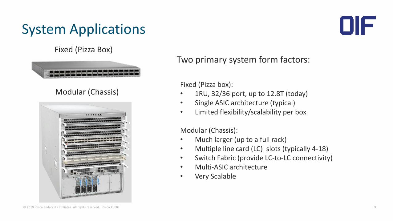
System Applications
Two primary system form factors:Fixed (Pizza Box)
Modular (Chassis)Fixed (Pizza box):• 1RU, 32/36 port, up to 12.8T (today)• Single ASIC architecture (typical)• Limited flexibility/scalability per box
Modular (Chassis):• Much larger (up to a full rack)• Multiple line card (LC) slots (typically 4-18)• Switch Fabric (provide LC-to-LC connectivity)• Multi-ASIC architecture • Very Scalable

© 2019 Cisco and/or its affiliates. All rights reserved. Cisco Public 10
Fixed Switch (e.g. 25.6T, 32x800G Pluggable)
SwitchASIC
RT8
ED 0D
PluggableModules
HostConnector
RT
Optical Interfaces
Copper Interfaces(Direct Attach)
e.g QSFP-DD800
ED 0D
CEI-112G-VSR
CEI-112G-MR
CEI-112G-LR
8
8
8
#1
#32
RT=Retimer, ED-Electrical Die, OD=Optical Die
8
Fan
s +
Pow
er S
up
plie
s
~ 17.5”
19-26”
25.6T Fixed Switch Platform (1 RU)
CEI-112G-MR
8
© 2019 Cisco and/or its affiliates. All rights reserved. Cisco Public 11
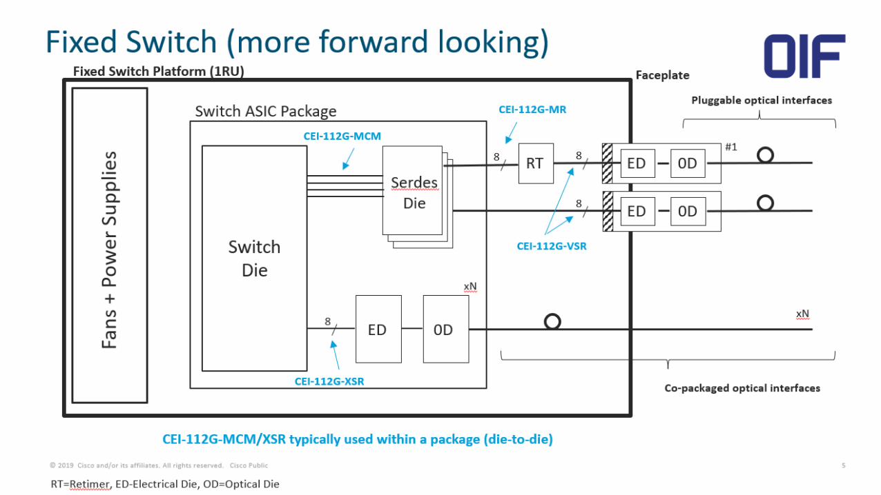
Fixed Switch (more forward looking)
RT8
ED 0D#1
8
8ED 0D
Fixed Switch Platform (1RU)
CEI-112G-VSR
Co-packaged optical interfaces
Pluggable optical interfaces
SwitchDie
CEI-112G-MCM
CEI-112G-XSR
8
Switch ASIC Package
SerdesDie
ED 0D
CEI-112G-MR
xN
proprietary interface ?
xN
Faceplate
Fan
s +
Pow
er S
up
plie
s
RT=Retimer, ED-Electrical Die, OD=Optical Die
CEI-112G-MCM/XSR typically used within a package (die-to-die)

© 2019 Cisco and/or its affiliates. All rights reserved. Cisco Public 12
Modular Switch
Fabric Cards (FC) Line Cards (LC)
CEI-112G-LR
Modular Switch Platform
• Front (customer) facing half of Line card is identical to Fixed Switch in terms of electrical interfaces:
• CEI-112G-VSR/MR/LR
• Main difference is the additional links required to interconnect the Line cards and Fabric cards:
• CEI-112G-MR/LR
Backplane

Click to edit Master title styleClick to edit Master subtitle style
CEI-112G: Status Update on VSR, and LR
Channels
Nathan Tracy, OIF President and TE Connectivity Technologist

What Happens When We Double The Data Rate?
14
Going from 50 Gbps to 100 Gbps electrical rates brings a host of challenges including noise (cross talk),
reflections, mode conversion, etc., but especially insertion loss (reach), because the equipment is the same
size as it was at 50 Gbps.
As we consider channels for 100 Gbps, we need lower loss architectures
-80
-70
-60
-50
-40
-30
-20
-10
0
0 10 20 30 40 50 60
dB
Lo
ss
Frequency GHz
1m 28AWG
1m Meg8
1m Meg6
1m FR4
Twinax cable
PCB
PCB
PCB

CEI-112G-VSR-PAM4
Interface for chip to module applications with a channel reach of at least 10 cm of host trace, one connector
and 2 cm of module trace
Defines compliance test methodology
VSR specifies Tx and Rx parameters at the connector compliance point since host assemblies and modules
are made by different parties
Alternate implementations are allowed
15

VSR Channel, Test vs Model Results, Existing 50Gbps Connector
Red Model (56G Connector)
Blue Test (56G Connector)
16
Note: Measured channel includes second set of vias to test point,
modeled channels do not include the second set of vias.

100G Connector Improvements (in the same 15dB channel)
Improved 100Gbps
OSFP connector
Efforts were focused on insertion
loss and return loss optimizations
Red Model (56G Connector)
Blue Test (56G Connector)
Pink Model (100G Connector)
17
Note: Measured channel includes second set of vias to test point,
modeled channels do not include the second set of vias.

CEI-112G-LR-PAM4
Interface for backplane applications with a channel reach of 100 cm over 1 or 2 mated connectors and
PCB and/or twinax cables.
Compliance point will be semiconductor ball.
18
Traditional Backplane Architecture
Cabled Backplane Architecture
Orthogonal Backplane Architecture

19 |
CEI-112G-LR InterfaceCathy Liu

20 |
CEI-112G-LR - Channels
CEI-112G-LR Chip Chip
Backplane or Passive Copper Cable
PAM4: Backplane or Cu cable interfaceIL: Up to 28dB at 28GHzFEC to relax BER to 1e-4
• Differentiations between CEI-112G and 802.3ck
– CEI covers more interfaces
– CEI covers wider range of baud rates
– CEI allows low latency and low cost FEC for VSR and XSR interfaces
• CEI-112G-LR COM and ERL define the channel compliance
– Insertion Loss target: 28dB at Nyquist
– ERL specifies channel effective return loss: 10.5dB
• Trade-offs between:
– Channel loss
– BER target
– Link rates
– Power and cost

21 |
• Latest CEI-112G-LR IA adopts
– 5-tap Tx FIR
– c(-3), c(-2), c(-1), c(0), and c(1)
– CTLE
– 2-zero and 3-pole
– DFE:– Floating tap DFE 12 fixed taps, 3 banks of 3 floating taps with 40UI span
– Coefficient constraints bmax(1)=0.85, bmax(2-3)=0.3, bmax(4-12)=0.2, bmax(floating)=0.05, bmin=-0.05
CEI-112G-LR – Reference Equalization
DFE schemes% passing channels(among green zone)
Floating DFE/53G/1e-4 97
16-tap DFE/53G/1e-4 86.6
Floating DFE/56G/1e-4 87.5
Floating DFE/56G/1e-5 41.3

Mike Peng Li
Intel

CEI-112G-XSR-PAM4 Link Requirements
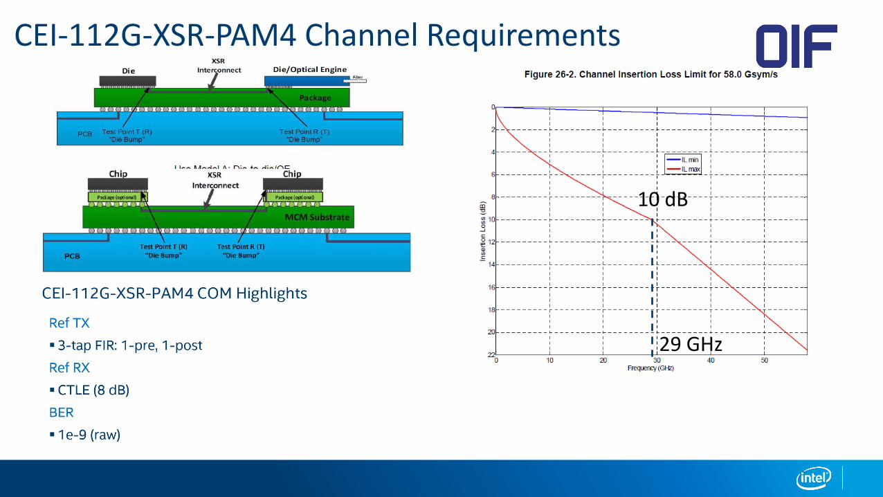
CEI-112G-XSR-PAM4 Channel Requirements
10 dB
29 GHz

Mike Peng Li
Intel

CEI-112G-MR-PAM4 Link Requirements

CEI-112G-MR-PAM4 Channel Requirements
20 dB
29 GHz

semtech.com
Ed FrlanPrincipal Product Definition Specialist, Semtech
CEI-112G MCM and VSR Interfaces

Copyright © Semtech Corporation 2020 All rights reservedsemtech.com
CEI-112G-MCM Overview
MCM applications based on
interconnected chiplets:
• Combination of many dies into large packages
• 2.5 cm can accommodate a 70 mm package
• Improvement in yield and cost over a monolithic IC
• Enables multi-vendor ecosystem
• I/O subsystem dies contain SerDes placed around the
perimeter, creating smaller virtual packages
Non-interposer MCMs
can easily use 20 or
more dies
CEI-112G-MCM key features:
• 2.5 cm bump-to-bump (up to 6 dB loss)
• CNRZ-5 modulation
• DC coupled path
• Silicon to silicon
• Clock forwarded
• Fat-pipe applications (i.e., between logic chips)
• System raw BER ≤ 10-15

Copyright © Semtech Corporation 2020 All rights reservedsemtech.com
CEI-112G-VSR Overview
112G VSR application:
• For next-generation higher density pluggable
modules (e.g., those based on 4x 100G or 8x
100G electrical interfaces)
• Still a traditional chip-to-module interconnect with
one connector
CEI-112G-VSR key features:• 16 dB channel insertion loss at 29 GHz
• PAM4 modulation with allowable range of 36 – 58 GBd
• System pre-FEC BER ≤ 10-6
• AC coupled channel with one connector
• Clocking based on per lane CDR function
• Receivers required to be self-adaptive and autonomous
• Acceptable system transmitter performance based upon reference receiver oscilloscope measurements via mated compliance boards at connector interfaces
• Reference receiver architecture is CTLE with 4-tap DFE
ChipPluggable
Optics
Chip to Module

Copyright © Semtech Corporation 2020 All rights reservedsemtech.com
CEI-112G-VSR Challenges
Tradeoff between equalizer capability and
expected channel performance
• Especially important for VSR and XSR types of
interfaces where transceiver pJ/bit is paramount
• 112G VSR transceiver efficiencies < 3 pJ/bit likely to
be enabled with simple equalization schemes
• Actual implementations may be Analog or DSP
VSR application space is larger than IEEE
802.3ck chip-to-module
• OIF BER < 10-6 (cf. IEEE 802.3ck BER < 10-5)
• OIF baud rate < 58 GBd (cf. IEEE baud rate = 53.1 GBd)
Sensitivity of PAM4 modulation to channel
discontinuities, especially for lower loss
interconnects
• Short channels exhibit significant sensitivity to present
package model discontinuities at the PCB interface
These reflections result in significant system penalties
ChipPluggable
Optics
Chip to Module

Steve Sekel 11 MAR 2020
400G Solutions Specialist Keysight Technologies

33
• Unlike CEI-53G Revolutionary shift from NRZ to PAM4, CEI-
112G is more Evolutionary
• Refinements to measurements used in CEI-56G - No major new
measurements added
• Assumption that receivers will be implemented with ADCs
• Margins are much tighter – artifacts which were considered
“too small” now need consideration
• Have we identified them all? - How close will actual measurements
match COM simulations?
• More complex reference receivers
E V O L U T I O N A R Y F R O M C E I - 5 6 G B A S E
112 Gbps Electrical Interfaces - an OIF Update on CEI-112G - Measurement Updates

34
• Receiver front end analog distortion and noise
• ADC sampling clock jitter
• ADC quantization noise
• Equalizer coefficient quantization effects
• Actual termination impedance versus nominal
• Differential skew errors
“ S M A L L ” A R T I F A C T S N O L O N G E R T O O S M A L L
112 Gbps Electrical Interfaces - an OIF Update on CEI-112G - Measurement Updates
ADC DSP

35
• Complete Reference Receiver implementation / optimization in both sampling and RT oscilloscopes
• Lab measurements with real SerDes outputs
• Compare with simulation
• Compare results measured with different instruments (Sampling and Real Time)
• Compare results measured with different vendors instruments
• In addition to obtaining repeatability, work will be required to speed measurement acquisition and
processing to a reasonable level
• (Measuring true EW-6*EH-6 product for optimization is much too slow!)
112 Gbps Electrical Interfaces - an OIF Update on CEI-112G - Measurement Updates
36
112 Gbps Electrical Interfaces: An OIF Update On CEI-112G
QUESTIONS?