Embed Size (px)
Citation preview

1176 IEEE TRANSACTIONS ON IMAGE PROCESSING, VOL. 21, NO. 3, MARCH 2012
Depth Video Enhancement Based on WeightedMode Filtering
Dongbo Min, Member, IEEE, Jiangbo Lu, Member, IEEE, and Minh N. Do, Senior Member, IEEE
Abstract—This paper presents a novel approach for depth videoenhancement. Given a high-resolution color video and its corre-sponding low-quality depth video, we improve the quality of thedepth video by increasing its resolution and suppressing noise. Forthat, a weighted mode filtering method is proposed based on a jointhistogram. When the histogram is generated, the weight based oncolor similarity between reference and neighboring pixels on thecolor image is computed and then used for counting each bin on thejoint histogram of the depth map. A final solution is determined byseeking a global mode on the histogram. We show that the proposedmethod provides the optimal solution with respect to � norm min-imization. For temporally consistent estimate on depth video, weextend this method into temporally neighboring frames. Simpleoptical flow estimation and patch similarity measure are used forobtaining the high-quality depth video in an efficient manner. Ex-perimental results show that the proposed method has outstandingperformance and is very efficient, compared with existing methods.We also show that the temporally consistent enhancement of depthvideo addresses a flickering problem and improves the accuracy ofdepth video.
Index Terms—Depth enhancement, depth sensor, multiscalecolor measure (MCM), temporal consistency, weighted modefiltering (WMF).
I. INTRODUCTION
P ROVIDING high-quality depth data has been one of themost important issues in the field of 3-D computer vision
and can be used in many applications such as image-based ren-dering, 3DTV, 3-D object modeling, robot vision, and tracking.The acquisition process of accurate depth data at high resolu-tion is nontrivial, and a variety of depth measuring methods havebeen developed. For example, although laser range scanner oractive illumination with structured lights can provide highly ac-curate depth data, they are available in the limited applicationssuch as a static environment only. Stereo matching methods canprovide a depth map in real-time through a support of special-ized hardware such as a graphics processing unit (GPU) [1], [2].A number of methods have been proposed by using several costaggregation methods [3], [4] and global optimization techniques[14], but their performance is still far from a practical solution
Manuscript received April 04, 2011; revised July 02, 2011; accepted July12, 2011. Date of publication July 29, 2011; date of current version February17, 2012. The associate editor coordinating the review of this manuscript andapproving it for publication was Dr. Anthony Vetro.
D. Min and J. Lu are with the Advanced Digital Sciences Center, Singapore138632 (e-mail: [email protected]; [email protected]).
M. N. Do is with the University of Illinois at Urbana-Champaign, Urbana, IL61820-5711 USA (e-mail: [email protected]).
Color versions of one or more of the figures in this paper are available onlineat http://ieeexplore.ieee.org.
Digital Object Identifier 10.1109/TIP.2011.2163164
due to lighting/occlusion problems, huge computational com-plexity, etc.
Recently, depth sensors such as time-of-flight (ToF) camerahave been widely used in research and practice. The ToF sensor,which is based on a special complementary metal–oxide–semi-conductor pixel structure, estimates the distance between thesensor and an object by extracting phase information from re-ceived light pulses [19]. Since it provides a 2-D depth map atvideo rate, it can be used in a dynamic environment [5]. How-ever, the quality of depth maps obtained by TOF camera is notsatisfactory due to an inherent physical limit of depth sensor.For example, depth maps obtained by a ToF sensor, i.e., “MesaImaging SR4000,” are of low resolution (176 144) and noisy[31].
In order to overcome the physical limit of the depth sensor,Diebel and Thrun proposed a depth upsampling method basedon MRF formulation by using a low-resolution depth map andits corresponding single high-resolution color image [7]. Theminimization problem with MRF formulation is solved with aconjugate gradient algorithm. However, the output depth maphas worse quality due to nonrobustness of a quadratic func-tion. Lu et al. [8] presented an MRF-based depth upsamplingmethod that uses a novel data term formulation which fits wellto the characteristics of depth maps. This method provides high-quality depth maps, but it is computationally heavy due to acomplex optimization technique. Park et al. [9] proposed anMRF optimization framework that combines the high-resolu-tion color image with a nonlocal means (NLM) method [23].They described an objective function that consists of data term,smoothness term, and NLM regularization term. In the smooth-ness term, a confidence weighting function is defined by usingcolor information, segmentation, edge saliency, and bicubic in-terpolated depth map. The NLM regularization term is utilizedto preserve thin structures by allowing pixels with similar struc-ture to reinforce with each other [9].
Kopf et al. [10] presented a general framework for multi-modal image enhancement and applied it to several image pro-cessing tasks such as colorization, tone mapping, and depth up-sampling. In particular, the low-resolution depth map is upsam-pled with a guide color image in the context of a bilateral fil-tering scheme by leveraging the color image as a prior. Yang etal. [11] proposed a new method for depth upsampling with aniterative joint bilateral upsampling (JBU). In contrast to the JBU[10] that applies the filtering procedure to the depth value, theybuild a 3-D cost volume based on current disparity value. Thejoint bilateral filtering is then performed for a 2-D cost sectionof each depth candidate, and a final disparity value is selectedby using the winner-takes-all (WTA) technique on the 3-D costvolume after a fixed number of iterations. The iterative bilateral
1057-7149/$26.00 © 2011 IEEE

MIN et al.: DEPTH VIDEO ENHANCEMENT BASED ON WEIGHTED MODE FILTERING 1177
filtering on the cost domain results in better edge-preserving per-formance, but its computational complexity is times of thatof the 2-D JBU [10], where is the number of depth candi-dates. Hierarchical depth upsampling [12] was proposed for anefficient implementation, but the complexity is still high and de-pendent on the number of depth candidates. In this paper, we callthe JBU by Kopf et al. [10] 2-D JBU, and the approach of Yanget al. [11] 3-D JBU. Another filtering-based depth upsamplingmethod [13] was proposed on the formulation of the nonlocalmeans method [23]. In order to enhance the quality of the depthmap while preserving fine details and depth discontinuities, anintrapatch similarity on the depth map and the correspondingcolor information are taken into account at the same time.
There are other existing methods for providing high-qualitydepth maps. Zhu et al. presented a method based on probabilisticfusion of ToF depth sensor and stereo camera [15]. Two costfunctions, which are calculated from the ToF and stereo cam-eras, are adaptively combined into a data term based on a re-liability value of each sensor data. A final energy function isdefined on MRF formulation with a smoothness constraint andsolved by loopy belief propagation [14]. This approach was ex-tended into spatial–temporal fusion for generating depth video,which is temporally consistent over frames [16]. They used aspatial–temporal MRF formulation for taking temporal neigh-bors, calculated by an optical flow method, into account.
Different from these approaches on fusion of stereo and ac-tive depth sensors, our method focuses on generating high-res-olution depth video with one color video (not stereo) and itscorresponding low-resolution depth video. For that, we proposea weighted mode filtering (WMF) based on a joint histogram.The weight based on similarity measure between reference andneighboring pixels is used to construct the histogram, and a finalsolution is then determined by seeking a global mode on the his-togram. The joint filtering means that the weight is computedwith a signal different from the signal to be filtered, and it en-ables the histogram to be extended into a weighted filtering. Wealso show that the proposed filtering technique forces the fil-tered value to be the solution for norm minimization, whichis more robust to outliers of data than norm minimization.
Weijer and Boomgaard proposed a local (not global) modefiltering, which is a histogram-based nonlinear filtering to pre-serve edges and details while suppressing noise on an image[17]. The histogram is computed from a set of data that consistsof neighbors of a reference pixel, and then, it seeks a local modeon the histogram iteratively after setting an intensity of the pixelas an initial solution. Given the pixel and its corresponding his-togram, the local mode filtering converges to the closest localmode on the histogram in an iterative manner [17]. In [18], itwas proved that the local mode filtering is equivalent to the bi-lateral filtering [6], which provides an optimal solution with re-spect to norm minimization.
Our proposed WMF provides a solution that is optimal withrespect to norm minimization, and it effectively enhances adepth video by deblurring and upsampling. Fig. 1 shows that theproposed method have the best edge-preserving performance.The synthesized view using the depth map upsampled by theproposed method is superior to those of the 2-D JBU and the 3-DJBU. We will describe this feature of the global mode filtering
and its relationship with the filtering-based methods in detaillater. Moreover, in order to model the characteristics of color in-formation on an image more accurately, a multiscale color mea-sure (MCM) is also proposed in the depth enhancement stepwhen sampling factor . The color similarity between thesparse depth data on the color image grid is measured on a multi-grid framework, and it leads to considering color distribution ofneighboring pixels between sparse depth data completely.
Another contribution of this paper is to enforce temporal con-sistency in the procedure for depth video enhancement. We ex-tend the WMF into a temporal domain, which generates an im-proved and flicker-free depth video. Temporal neighbors are de-termined by an optical flow method, and a patch-based relia-bility measure of the optical flow is used further in order to copewith errors of the estimated optical flow. This is a simplified for-mulation of a nonlocal video denoising [23]. Although the non-local video denoising shows excellent performance since it usesa set of all the possible pixels on the temporally neighboringframes, its complexity is huge. Our approach hence selects onepixel corresponding to the estimated optical flow for each frame.Since it uses the additional color information for enhancing thedepth video, one optical flow vector and its patch-based relia-bility measure are enough to reduce the flickering problem andimprove the performance, which is similar to [16].
The remainder of this paper is organized as follows: In Sec-tion II, we present the depth enhancement based on the WMFand discuss the relations to other joint filtering approaches suchas the 2-D JBU [10], the 3-D JBU [11], and a histogram-basedvoting [22]. The MCM and temporally consistent estimateare then described in Sections III and IV. Finally, we presentexperimental results and conclusion in Sections V and VI,respectively.
II. WEIGHTED MODE FILTERING FOR DEPTH ENHANCEMENT
In general, the quality of depth video can be measured by theamount of noise, spatial resolution, and temporal consistency.Therefore, the depth video can be improved by suppressingthe noise, increasing its spatial resolution, and handling thetemporal flickering problem. In this paper, we propose a novelmethod based on the joint histogram for achieving these goals.
A. WMF on Histogram
Histogram of an image represents the number of pixels insidegiven rectangular (or any shape) regions, which corresponds toeach bin, and can be referred to as a probability distribution ofpixel values after a normalization step. The local mode filtering[17] constructs a relaxed histogram where each pixel is modeledby Gaussian distribution. Given 2-D function of an image,relaxed histogram at reference pixel and th bin canbe defined as follows:
(1)
where is a Gaussian function and represents a set ofneighboring pixels of pixel . In order to compute localized his-

1178 IEEE TRANSACTIONS ON IMAGE PROCESSING, VOL. 21, NO. 3, MARCH 2012
Fig. 1. Depth upsampling results for “Teddy” image: (a) Ground truth depth map, (e) 2-D JBU [10], (i) 3-D JBU [11], and (m) proposed method (WMF �MCM). The upsampling ratio is 8 in each dimension. The processing times are (e) 0.95, (i) 220, and (m) 0.55 s, respectively. The processing time of the proposedmethod is 0.25% of that of 3-D JBU, while it has the best edge-preserving performance. The virtual view is synthesized by using an original color image and thecorresponding upsampled depth map. We can see that the enhanced depth and the virtual view of the proposed method are superior to those of 2-D JBU and 3-DJBU. (a) Ground truth depth map. (b) Cropped image of (a). (c) Synthesized view using (a). (d) Cropped image of (c). (e) Two-dimensional JBU. (f) Cropped imageof (e). (g) Synthesized view using (e). (h) Cropped image of (g). (i) Three-dimensional JBU. (j) Cropped image of (i). (k) Synthesized view using (i). (l) Croppedimage of (k). (m) Proposed method. (n) Cropped image of (m). (o) Synthesized view using (m). (p) Cropped image of (o).
togram around pixel , spatial Gaussian functionis also introduced as follows:
(2)
Pixels that are closer to reference pixel have a largerweighting value. Local mode filtering then seeks local mode
that is the closest to intensity of reference pixel .In other words, the local minimum which is close to the initialvalue is chosen among a set of multiple local minima and [17]shows its effectiveness on an image denoising. Paris et al. [18]shows that the iterative local mode seeking step is equivalent to
an iterative bilateral filtering. The th solution forthe local mode filtering can be computed as follows:
(3)Bilateral filtering is a nonlinear summation for smoothing an
image while maintaining edges and details [6]. Its main idea is tocombine color and spatial similarity measure between referenceand neighboring pixels. A number of works have shown the re-lation between bilateral filtering, robust statistics, and nonlineardiffusion based on a Bayesian framework [20]. Elad [21] provedthat the bilateral filtering is a solution after one iteration of the

MIN et al.: DEPTH VIDEO ENHANCEMENT BASED ON WEIGHTED MODE FILTERING 1179
Jacobi algorithm on Bayesian approach. The energy function isdefined by using weighted least square based on norm, anda weighting function is defined by a Gaussian distribution. Thismethod can be extended into the joint bilateral filtering [10] byusing guide signal different from reference signal tobe filtered as follows:
(4)
where is a Gaussian function for whose value does notchange over the iteration.
This paper proposes the weighted mode filtering that seeksglobal mode on the histogram by leveraging similarity measurebetween data of two pixels. When histogram for theweighted mode filtering is generated, the data of each pixel in-side rectangular (or any shape) regions is adaptively counted onits corresponding bin by using data similarity between referenceand neighboring pixels, i.e.,
(5)In this paper, , , and are defined as
Gaussian functions, where means are 0 and standard deviationsare , , and , respectively. Final solution for theWMF can be computed as follows:
(6)
Here, is a 2-D function where each pixel has a specificdata. In this paper, we focus on the WMF where is a weightfunction of guide signal different from reference signal
to be filtered. Since the guide signal is employed for cal-culating data-driven adaptive weight , the proposed filteringis contextualized within the joint bilateral filtering framework[10]. However, as shown in Fig. 1, it has better edge-preservingperformance than the joint bilateral filtering on the object dis-continuities. The relation with the joint bilateral filtering will bedescribed in the following section. The performance and effec-tiveness of the proposed method are verified by applying it todepth video enhancement, provided from ToF depth sensor. Inthe case of the depth enhancement task, is color imageand is depth image .
Fig. 2 explains the procedure that generates joint histogram. Neighboring pixels and of reference pixel are
adaptively counted with a form of Gaussian function on eachbin corresponding to their disparity values. The bandwidth andmagnitude of Gaussian function are defined by standard devia-tion of and the magnitude of , respectively. Stan-dard deviation of Gaussian spreading function is usedfor modeling errors that may exist on the input depth data. Inother words, the neighboring pixels are adaptively accumulatedon joint histogram by using color and spatialsimilarity measures and Gaussian error model .
Fig. 2. Joint histogram generation: Joint histogram� of reference pixel � iscalculated by adaptively counting neighboring pixels� and� with a form ofGaussian function according to their disparity values � and � . The bandwidthand magnitude of the Gaussian function are defined by standard deviation � of� and the magnitude of � � , respectively.
In general, a depth value smoothly varies inside objects andhas sharp discontinuities on the object boundaries. When thedepth is upsampled by the 2-D JBU, the filtered output depthvalue is provided by using an adaptive summation based oncolor information. Although an adaptive weight based on colorinformation is used for preserving edges, it still results in un-necessary blur due to its summation.
B. Relations With Other Joint Filtering Approaches
As previously mentioned, there are some existing approachesfor the depth enhancement (upsampling). Here, we discuss therelations with the existing approaches, particularly for the joint-filtering-based methods.
1) 2-D JBU: The 2-D JBU is an adaptive summation with aguide of corresponding color image [10]. We modify joint his-togram in (5) by replacing with delta function
, which is 1 when , 0 otherwise, i.e.,
(7)
The joint bilateral filtering can be then written by using (7) asfollows:
(8)We can find that the joint bilateral filtering computes the
output depth value by adaptively summing all depth candidatesaccording to joint histogram , whereas the WMF in (6)selects the output depth value whose histogram value is thelargest among all depth candidates. Fig. 3 shows the relationbetween the 2-D JBU and the WMF on the joint histogram.In other words, the joint bilateral filtering provides a meanvalue through the adaptive summation, which is optimal withrespect to norm minimization. In contrast, the WMF picksthe output value that has the largest histogram value, whichis optimal with respect to norm minimization. Anotherdifference is that the joint bilateral filtering uses delta function

1180 IEEE TRANSACTIONS ON IMAGE PROCESSING, VOL. 21, NO. 3, MARCH 2012
Fig. 3. Relation between 2-D JBU and WMF. The joint bilateral filtering pro-vides the mean value through the adaptive summation (� norm minimization),whereas the WMF picks the output value that has the largest histogram value(� norm minimization).
for modeling each depth data inside window , namely,weighting parameter of is 0 in (5).
The joint bilateral filtering has two parameters, i.e., thatdefines the data-driven smoothing and that defines the spa-tial locality of the neighboring pixels. In contrast, the weightedmode filtering has three parameters, i.e., two parameters that arethe same to those of the joint bilateral filtering and that de-cides the bandwidth of the Gaussian function, as shown in Fig. 2.
As increases on the joint bilateral filtering, in (4)corresponds to a standard Gaussian filtered value, which resultsin a blurred output on the object discontinuities. In the WMF, as
increases, the global mode of joint histogram approaches thesolution of the joint bilateral filtering. Fig. 4 shows the resultsof the WMF and the joint bilateral filtering (which is equiva-lent to local mode filtering). We found that as increases, theresults of the WMF become similar to those of the joint bilat-eral filtering. In particular, when , the results of twomethods are almost same. Note that these results were all es-timated with the same initial depth map (original sparse depthmap) by using a MCM, which will be described in the followingsection. Therefore, the result in Fig. 4(d) of the joint bilateral fil-tering is different from that in Fig. 1(a).
2) 3-D JBU: The 3-D JBU [11] builds a 3-D cost volumeby using a current depth map and then perform
the joint bilateral filtering for 2-D cost section of each depthcandidate. For an initial input disparity map , the 3-D JBUis performed as follows:
(9)
(10)
(11)
where is a threshold for truncation at the penalty function(9). Although it has a better performance than the 2-D JBU, thecomputational complexity is huge. If the complexity of the 2-DJBU is , the 3-D JBU has a complexity of ,
Fig. 4. WMF versus joint bilateral filtering (local mode). (a)–(c) The results ofthe WMF. As � increases, the results of the WMF become similar to that of thejoint bilateral filtering. Note that the result in (d) is different from Fig. 1(a) sincethe depth maps were upsampled by the MCM with original sparse depth map,which will be described in the following section. (a) � � ���. (b) � � ����.(c) � � ����. (d) Two-dimensional JBU � MCM.
where and are the size of image and window , respec-tively. is the number of depth candidates, and representsthe number of iterations. In this paper, is set to 1, namely, itis a noniterative scheme.
The 3-D JBU computes the output depth value by finding theminimum value among the depth candidates on the 3-D costvolume. In a sense that the WMF computes the solution byfinding the maximum on the joint histogram, the 3-D JBU andthe WMF use a similar principle. For finding a maximum valueon the 3-D cost volume, we redefine cost function asfollows:
(12)
After applying the same joint bilateral filtering in (10), an outputdepth value, which is a maximum value on the 3-D cost volume,is the same to the solution in (11). If we assume that the new costfunction is an approximated one of Gaussian function
in (5), 3-D cost volume in (10) plays a similar role tojoint histogram in (5), except that is computedafter the normalization step. Fig. 5 shows the relation between
and , where is omitted. and model errors ofthe input depth map with Gaussian function and linear function,respectively.
The computational complexity of the WMF can be defined as, where is the width of the Gaussian function
in Fig. 5 and determined by the number of depth candidatesand weighting parameter , which depends on the amount ofnoise in the input depth map. In this paper, when the numberof depth candidates is 256, is set to 9–39. Since the 3-DJBU performs the joint bilateral filtering for all depth candi-dates, which consists of the adaptive summation and normal-ization step, the computational complexity is much higher thanthat of the WMF. We will show the complexity analysis in theexperimental results.

MIN et al.: DEPTH VIDEO ENHANCEMENT BASED ON WEIGHTED MODE FILTERING 1181
Fig. 5. Relation between � ��� in (5) and � ��� in (12), where � is omitted.� can be referred to as the approximated one of Gaussian function � .
3) Histogram-Based Voting: Lu et al. proposed a votingmethod based on a histogram for estimating the depth map onstereo images [22]. The voting method is used for refining theinitial depth map on the histogram. It estimates an adaptiveregion for each pixel with an anisotropic local polynomialapproximation (LPA) technique and builds the histogram withdepth values inside the estimated region. The histogram is thenused for refining the initial depth map. While our method isbased on the joint histogram with a soft constraint, this canbe referred to as the histogram-based approach with a hardconstraint since the histogram is counted with a constant value(usually 1) on the adaptive region, which is determined by theLPA technique.
III. MCM
Here, we propose a method for measuring a color distance inthe multiscale framework. Note that this method is for depth up-sampling only. In other words, the MCM is used for preventingan aliasing effect that may happen in the depth upsampling task.
The sparse original depth values mapped into the colorcamera coordinate only are used for preventing the outputdepth value from being blurred on the depth boundaries,different from previous approaches [10], [11], which usedinterpolated depth values to initialize the input depth map. Inorder to include this notation in (5), we define binary function
, whose value is 1 when has an original depth value, 0otherwise. Histogram can be expressed as follows:
(13)As shown in Fig. 6, however, if we use the sparse original
depth values for the depth upsampling directly, it may cause thealiasing artifact due to different size between the original depthand color images. In (13), since color distance ofneighboring pixels are calculated by using sparse pixels onlywhere they have depth values , this color mea-sure cannot represent the distribution of color information in-side window . The existing methods [10], [11] have han-dled this problem by applying prefiltering methods such as bi-linear or bicubic interpolation. However, this initial depth mapcontains contaminated values that may cause serious blur on thedepth boundaries. In this paper, we handle this problem by usingthe MCM, instead of applying the prefiltering techniques. Thismethod can provide an aliasing-free upsampled depth map andpreserve the depth discontinuities well.
Fig. 6. Aliasing effect in the depth upsampling: Different from the previousapproaches that use the bilinear or bicubic interpolations based on low-pass fil-tering, the sparse original depth values are used only in the proposed method.However, this may result in the aliasing effect, as shown in (a). This problemcan be handled by using the MCM in (c). (a) Aliased depth map. (b) Croppedimage of (a). (c) Fig. 1(c) (with MCM). (d) Cropped image of (c).
Before explaining the method in detail, we define someparameters for helping readers to understand it. Specif-ically, let the resolution difference between the originallow-resolution depth map and high-resolution color image
, where and are theheight of the depth and color images, respectively, and and
are width of the depth and color images, respectively. Thenumber of level on the multiscale frameworkis set to . Window on th level is defined as
, where is the size of the windowon the original small depth domain. Namely, the actual size ofwindow is dependent on the upsampling ratio since thesparse original depth values only are used. We also define anew Gaussian filtered color image , which is usedfor calculating the color distance on each level of the multiscaleframework.
The sparse depth map can be upsampled by using (13) ina coarse-to-fine manner. Table I shows the pseudocode of thedepth upsampling with the MCM. Gaussian lowpass-filteredcolor image is first computed for each level, and the WMFis performed on each level by using the original and upsampleddepth values only. For instance, if is 3, the upsamplingprocedure starts for every pixels on the coarsest level,and binary function of these pixels are set to 1. In otherwords, the depth value of pixels upsampled on the currentlevel can be used on the next level again. The variance of theGaussian function for low-pass filtering of is proportionalto the ratio of downsampling on each level. Different from theconventional downsampling procedure where low-pass filteringis first applied and an image is then downsampled, Gaussianlow-pass filtered color image is first computed and colordistance is then calculated on the full

1182 IEEE TRANSACTIONS ON IMAGE PROCESSING, VOL. 21, NO. 3, MARCH 2012
TABLE IPSEUDOCODE OF DEPTH UPSAMPLING WITH MCM ON HIERARCHICAL SCHEME
Fig. 7. Example of depth upsampling with MCM on hierarchical scheme:When scale � �, blank pixels are upsampled for every ��� � � pixels withoriginal and upsampled depth values on the full resolution grid. Note that theGaussian filtered � � � � � are used for calculating the color distance oneach level. (a) Initial (nonregular) depth. (b) Scale � � (for every 4 pixels). (c)Scale � � (for every 2 pixels). (d) Scale � � (for all pixels).
resolution grid (not coarse resolution grid). In other words,filtered color image is not downsampled.
Fig. 7 shows an example of the depth upsampling with theMCM. Note that the depth and color images are always pro-cessed on the full resolution. Given the initial sparse (irregu-larly sampled) depth map, the depth values on the th level areupsampled (refined) for every pixels by using neighboringpixels on the full resolution inside . Instead of changingthe size of the color and depth images, the processing unit forupsampling adjusts on each level. This multiscale scheme hastwo advantages. First, since the size of the color and depth im-ages is the same to all levels, an additional memory used on thecoarse level is not needed. Second, the initial sparse depth map,warped into the color camera coordinate, is generally irregularlysampled. Therefore, downsampling of the depth map may losesome information of the irregularly sampled depth data on thecoarse domain. The proposed method can consider the irregu-larly sampled depth data completely on the full resolution forall levels.
IV. ENFORCING TEMPORAL CONSISTENCY
In order to apply the proposed method to the depth video,temporal consistency should be considered by using the infor-mation of temporally neighboring frames. Temporally consis-tent estimate of the correspondences from the low-quality depthvideo provides a flicker-free depth video and improves the ac-curacy of an output depth video.
There are some requirements when enforcing temporal con-sistency. First, an additional complexity for the temporally con-sistent estimate should be small compared to that of the WMFfor a single depth image. The temporal consistency is enforcedfor handling the flickering problem and improving the qualityfrom the temporal aspect; thus, it is not suitable and meaningfulto use a computationally heavy algorithm whose complexity ishigher than that of the WMF for a single depth map. Second,the information of the temporal neighbors should be incorpo-rated in a way that is robust to errors on the depth discontinu-ities. Considering the temporal aspect may cause some prob-lems due to errors that might exist on the information of thetemporal neighbors on the depth discontinuities, where a mo-tion vector is generally difficult to estimate. In this paper, thetemporal neighbors are determined by Lucas–Kanade (LK) op-tical flow method [25], [26], and a patch-based reliability mea-sure is used for handling the error of the optical flow. Recently, anumber of optical flow estimation methods have been proposed[27]. However, their performance is still far from a practical so-lution, and the complexity is still too huge to be used in thisapplication.
The LK tracker generally allows estimating a small displace-ment only over two frames and provides erroneous results onthe depth boundaries. We hence use the patch-based reliabilitymeasure between reference pixel on the th frameand corresponding pixel on the th frame with the estimatedoptical flow together, when combining the joint histograms ofthe temporally neighboring frames. Fig. 8 shows the WMF forthe temporally neighboring depth frames. The temporally con-sistent joint histogram of the th frame can be com-puted through an adaptive summation of the joint histograms ofthe temporal neighbors, i.e.,
(14)
represents the neighboring frames of the th frame. Notethat is an output joint histogram after applying a tempo-rally adaptive summation on the th frame. Patch reliability mea-sure can be computed as follows:
(15)
In this paper, the size of neighboring pixels and are set to5 5 and 40, respectively. Weighting function is computedby the patch-based reliability measure between on the originalth frame and on the th frame and then normalized with ,
namely, .

MIN et al.: DEPTH VIDEO ENHANCEMENT BASED ON WEIGHTED MODE FILTERING 1183
Fig. 8. Temporal neighboring frames for weighted mode filtering.
In order to reuse the temporally consistent estimates onthe previous frames, we divide into previous neighbors
and next neighbors , respectively, i.e.,
(16)
In other words, joint histogram , which is computed onthe th frame, is reused as an input joint histogram on theframe.
This formulation is similar to a nonlocal video denoising [23],which uses the patch-based similarity measure on the neigh-boring frames. Although it provides the excellent performanceand is easy to implement, the complexity is huge since all pos-sible pixels on the temporally neighboring frames are used. Inthis paper, we hence use a simplified approach that uses boththe simple optical flow and the patch-based reliability, which ismotivated by the nonlocal means approach. Fig. 9 shows a re-lation between the nonlocal means approach and the proposedmethod. Single pixel on each frame is used only so that the com-plexity is small. The errors of the estimated optical flow are sup-pressed by patch-based reliability measure . Since the addi-tional color information is also used for enhancing the depthvideo, one optical flow vector and its patch-based reliabilitymeasure are enough to reduce the flickering problem and im-prove the accuracy.
V. EXPERIMENTAL RESULTS
We have verified the performance of the proposed methodthrough various experiments in terms of edge-preserving perfor-mance, noise suppression, flickering reduction, and complexity.The performance was compared with the 2-D JBU [10] and the3-D JBU [11]. All the experiments were performed on a Delllaptop, which consists of Intel i5 2.4-GHz central processingunit and 6-GB random access memory. We need to classify thedepth enhancement task into two categories according to the sizeof the input depth map: 1) depth upsampling and 2) depth re-finement. In the depth upsampling task, the input depth maps,which are noisy and of low resolution, are upsampled with theMCM. In contrast, the depth refinement task improves the ac-curacy of the input depth maps, estimated by existing stereo
Fig. 9. Nonlocal means and the proposed scheme. In the proposed method,single pixel, which is estimated by the optical flow, is used only, whereas thenonlocal means filtering uses all possible pixels. The errors of the estimatedoptical flow is suppressed by patch-based reliability measure � . (a) Nonlocalmeans for video. (b) Proposed scheme.
Fig. 10. Experimental setup for the proposed method. The capturing systemconsists of a “Point Grey Flea” color camera and a “Mesa Imaging SR4000”depth sensor.
matching methods [2]. Thus, the MCM is not used since thecolor image and its corresponding input depth map are of thesame resolution.
A. Geometric Calibration for Fusing Depth and Color Sensors
Given a noisy depth map with low resolution, our goal isto enhance its quality and/or resolution efficiently and accu-rately, particularly for the depth discontinuities, by using itscorresponding color image. Note that the color image shouldbe aligned with the depth map spatially and temporally as theyshould be acquired at the same viewpoint and time. As shown inFig. 10, our system consists of a “Mesa Imaging SR4000” depthsensor [31] and a “Point Grey Flea” color camera [32] for ac-quiring the depth and color videos. Since frame rates of the colorand depth sensors are different, time stamps are used to syn-chronize two sensors. For the spatial alignment, we performedcamera calibration and mapped depth data into the color cameracoordinate. After calculating a calibration matrix that consistsof intrinsic and extrinsic parameters, the depth data providedby the ToF depth sensor is mapped into an image coordinate of

1184 IEEE TRANSACTIONS ON IMAGE PROCESSING, VOL. 21, NO. 3, MARCH 2012
the color sensor. Specifically, let the projection matrices of thedepth and color sensors be and
, respectively, and the homogeneous image co-ordinate on the depth and color images and
, respectively. Given depth value of pixelon the depth image, 3-D point at the world coordinate
corresponding to pixel is computed as follows:
(17)
The 2-D point and its corresponding 3-D pointon the color sensor are then computed
with the intrinsic and extrinsic parameters , , and asfollows:
(18)
Finally, the depth map aligned on the color image is assignedwith . Note that this depth value is the distancebetween object and color cameras, different from displacementvector (pixel) of stereo matching algorithms. When the depthimage is smaller than the color image, namely, the samplingfactor , the warped depth image has sparse depth valuesonly. Additionally, due to occlusion, some background points,which should be removed as occluded points, might be mixedwith foreground points whose depth values are smaller than thatof background points. In order to remove these occluded depthvalues, we used a smoothness constraint of 3-D surface [24]. Ifthe depth value of the pixel in the warped depth image is largerthan those of neighboring pixels, the pixel is considered to beoccluded and removed from the warped depth image.
B. Depth Upsampling
We have implemented the proposed method and evaluatedthe performance by using the depth video, provided by ToFdepth sensor “Mesa Imaging SR4000.” For the objective eval-uation, we first performed experiments with ground truth depthmaps provided by the Middlebury test bed [2], i.e., “Tsukuba,”“Venus,” “Teddy,” and “Cone.” They provide stereo image pairsand corresponding depth maps. Low-quality depth map, whichis generated by downsampling the ground truth depth map, isupsampled by the proposed method.
The proposed method is tested with the same parametersfor all images. Weighting parameters and in (4) are setto 6 and 7, respectively. is determined by bandwidthof Gaussian function . We compute weighting parameter
, which meets condition . Then, canbe expressed as . When thenumber of depth candidates is 256 and the input depth map isnoise-free, bandwidth is set to 9. In the case of a noisy depthmap, bandwidth increases for taking the noise into accountin the input depth map. In this paper, we set a maximum valueof bandwidth to 39. Note that bandwidth plays a similarrole as threshold of the 3-D JBU in (12).
The size of window on the original small depth domainis 2. Although the size of window changes on each levelwhen the MCM is used, the number of the neighboring depthvalues, which are used for computing joint histogram ,is approximately similar on all levels. In Fig. 4, when scale is
2, the depth value is computed for every pixels so thatactual window is on and axes.
Fig. 11 shows the results of the proposed depth upsamplingmethod for the test bed images, when the downsampling ratio is8 in each dimension. The results of the 2-D JBU [10] and the 3-DJBU [11] were included for a visual evaluation. Note that thesemethods used the bilinear interpolation technique for computingthe initial input (dense) depth maps. The size of window isset to 11 11 since the MCM is not used. In order to fairly com-pare the performance of the filtering-based methods by using thesame input depth maps, the results that were upsampled with theMCM were included as well, i.e., 2-D JBU MCM and 3-DJBU MCM. Note that the 2-D JBU (3-D JBU) uses the inter-polated (dense) depth map as an input value, whereas the 2-DJBU (3-D JBU) MCM uses the original (sparse) depth map.
The proposed method yields the superior results over the ex-isting methods, particularly on the depth discontinuities. Theperformance of the 3-D JBU MCM is very similar to that ofthe WMF since the MCM prevented the upsampled depth mapfrom being blurred on the depth discontinuities. The 2-D JBUMCM does not improve the edge-preserving performance, evencompared with the 2-D JBU that used the blurred depth mapsas the initial value. We can hence conclude that the 2-D JBU orthe 2-D JBU MCM results in the blurred depth map due to itssummation over all depth candidates, even though they use theadaptive weight based on color information and the MCM on thehierarchical scheme. The objective evaluation of these methodsis shown in Table II. The accuracy is evaluated by measuringthe percent (%) of bad matching pixels (where the absolute dis-parity error is greater than 1 pixel). The measurement is com-puted for two subsets of a depth map, i.e., all (all pixels in theimage) and disk (the visible pixels near the occluded regions).As expected, the proposed method (WMF MCM) is superiorto the existing methods (2-D JBU and 3-D JBU) and comparableto the 3-D JBU MCM.
The processing time of the methods is presented in Table III.The processing time of the 2-D JBU MCM is the smallestamong all methods, but its quality is the worst. Although the 3-DJBU MCM has a similar accuracy to the proposed method,the computational complexity of the proposed method is nearly0.8% of that of the 3-D JBU MCM. Since the 3-D JBU per-forms the joint bilateral filtering for all depth candidates repeat-edly, it results in huge computational complexity.
The results for noisy depth maps are also shown in Fig. 12.Additive white Gaussian noise (AWGN) was added with a meanof 0 and a standard deviation of 20 to the low-resolution depthmaps, whose downsampling ratio is 8 in each dimension. Band-width of in (4) is set to 39. We found that the proposedmethod provides the accurate high-resolution depth map, evenwhen the input depth map is very noisy.
C. Depth Refinement
Next, the depth enhancement method is evaluated by applyingit to refining depth maps, which were estimated by several ex-isting stereo matching algorithms [2]. As previously mentioned,the MCM is not used. Namely, the depth map is refined witha nonhierarchical scheme. All the parameters are the same to

MIN et al.: DEPTH VIDEO ENHANCEMENT BASED ON WEIGHTED MODE FILTERING 1185
Fig. 11. Depth upsampling results for test bed images: (a) Initial low-resolution depth maps whose downsamping ratio is 8 in each dimension, (b) 2-D JBU results[10], (c) 2-D JBU � MCM, (d) 3-D JBU [11], (e) 3-D JBU � MCM, and (f) proposed method (WMF � MCM).
those of the depth upsampling, except that window size isset to 7 7.
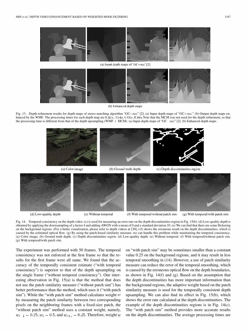
Fig. 13 shows the original depth maps and the enhanced ones,which were calculated by the stereo matching method [2]. The
results for “GC occ” algorithm are shown here. We could findthat the proposed filtering improves the accuracy of the depthmaps for the discontinuities and occluded regions. Table IVshows an objective evaluation for the depth refinement by mea-

1186 IEEE TRANSACTIONS ON IMAGE PROCESSING, VOL. 21, NO. 3, MARCH 2012
TABLE IIOBJECTIVE EVALUATION (THE PERCENT (%) OF BAD MATCHING PIXELS) FOR DEPTH UPSAMPLING ON ALL (ALL PIXELS IN THE IMAGE) AND
DISK (THE VISIBLE PIXELS NEAR THE OCCLUDED REGIONS) REGIONS WITH THE MIDDLEBURY TEST BED
Fig. 12. Depth upsampling results in noisy environment: The downsampling ratio is 8 in each dimension, and AWGN was added with a mean of 0 and a standarddeviation of 20. (a) Input noisy depth maps. (b) Upsampled depth maps.
TABLE IIIPROCESSING TIMES OF DEPTH UPSAMPLING FOR MIDDLBURY TEST BED
TABLE IVOBJECTIVE EVALUATION (AVERAGE RANK OF DEPTH MAPS) OF SEVERAL
EXISTING STEREO MATCHING ALGORITHMS “BEFORE” AND “AFTER”APPLYING OUR PROPOSED DEPTH REFINEMENT TECHNIQUE
suring an average rank of the depth maps. The proposed methodimproves the accuracy of the depth maps for almost all the al-gorithms, even for the top-ranking algorithms such as “Adapt-ingBP” or “DoubleBP” [2]. In “GC SegmBorder,” the outputresult is a little worse . The proposed method islikely to provide a piecewise constant value so that the outputdepth map was slightly degenerated at the piecewise linear re-gions of “Teddy” image. The processing times of the depth en-hancement are 0.42 s for “Tsukuba,” 0.64 s for “Venus,” 0.66 sfor “Teddy,” and 0.66 s for “Cone.”
D. Temporal Consistency
In order to evaluate the temporally consistent estimate perfor-mance of the proposed method, we performed experiments withcolor and ground truth depth videos “Tanks” (400 300), pro-vided by [28]. The color and depth videos can be downloaded at[29]. The ground truth depth video is downsampled by a factorof 4, and AWGN was then added with a mean of 0 and a standarddeviation of 10. The number of the set of neighboring frames
in (14) is set to 2. Namely, th and th framesare used for calculating . Fig. 14 shows upsampled re-sults given by the proposed method. As shown in Fig. 14(f) and(g), we can cope with problems caused by the error of the esti-mated optical flow on the depth discontinuities. The input andoutput depth videos are available at [30].
For objective evaluation, we measured the percent (%) of badmatching pixels with the ground truth depth video in Fig. 15.
MIN et al.: DEPTH VIDEO ENHANCEMENT BASED ON WEIGHTED MODE FILTERING 1187
Fig. 13. Depth refinement results for depth maps of stereo matching algorithm “GC�occ” [2]. (a) Input depth maps of “GC�occ.” (b) Output depth maps en-hanced by the WMF. The processing times for each depth map are �����, �����, �����, ����� Note that the MCM was not used for the depth refinement, so thatthe processing time is different from that of the depth upsampling (WMF � MCM). (a) Input depth maps of “GC�occ” [2]. (b) Enhanced depth maps.
Fig. 14. Temporal consistency on the depth video: (c) is used for measuring an error rate on the depth discontinuities region in Fig. 15(b). (d) Low-quality depth isobtained by applying the downsampling of a factor 4 and adding AWGN with a mean of 0 and a standard deviation 10. (e) We can find that there are some flickeringon the background regions. (For a better visualization, please refer to depth videos at [30].) (f) shows the erroneous result on the depth discontinuities, which iscaused by the estimated optical flow. (g) By using the patch-based similarity measure, we can handle this problem while maintaining the temporal consistency.(a) Color image. (b) Ground truth depth. (c) Depth discontinuities region. (d) Low-quality depth. (e) Without temporal. (f) With temporal/without patch sim.(g) With temporal/with patch sim.
The experiment was performed with 50 frames. The temporalconsistency was not enforced at the first frame so that the re-sults for the first frame were all same. We found that the ac-curacy of the temporally consistent estimate (“with temporalconsistency”) is superior to that of the depth upsampling onthe single frame (“without temporal consistency”). One inter-esting observation in Fig. 15(a) is that the method that doesnot use the patch similarity measure (“without patch sim”) hasbetter performance than the method, which uses it (“with patchsim”). While the “with patch sim” method calculates weightby measuring the patch similarity between two correspondingpixels on the neighboring frames with a fixed-size patch, the“without patch sim” method uses a constant weight, namely,
, , and . Therefore, weight
on “with patch sim” may be sometimes smaller than a constantvalue 0.25 on the background regions, and it may result in lesstemporal smoothing in (14). However, a use of patch similaritymeasure can reduce the error of the temporal smoothing, whichis caused by the erroneous optical flow on the depth boundaries,as shown in Fig. 14(f) and (g). Based on the assumption thatthe depth discontinuities has more important information thanthe background regions, the adaptive weight based on the patchsimilarity measure is used for the temporally consistent depthupsampling. We can also find its effect in Fig. 15(b), whichshows the error rate calculated at the depth discontinuities. Theexample of the depth discontinuities regions is in Fig. 14(c).The “with patch sim” method provides more accurate resultson the depth discontinuities. The average processing times are

1188 IEEE TRANSACTIONS ON IMAGE PROCESSING, VOL. 21, NO. 3, MARCH 2012
Fig. 15. Percent (%) of bad matching pixels on depth video upsampling. (a) Error rate for all pixels. (b) Error rate for pixels on the depth discontinuities.
Fig. 16. Upsampling results for low-quality depth image (from “Mesa Imaging SR4000”) with corresponding color image (from “Point Grey Flea”). The sizesof the input depth and color images are 176 � 144 and 1024 � 768, respectively. The depth maps, acquired by the depth sensor, were normalized between 0 and255. (a) Color image. (b) Two-dimensional JBU. (c) Three-dimensional JBU. (d) Proposed method. (e) Initial depth map. (f) Cropped image of (b). (g) Croppedimage of (c). (h) Cropped image of (d).
Fig. 14(e) 0.60, (f) 0.91, and (g) 0.98 s, respectively. In otherwords, an additional processing time for the temporally consis-tent estimate of “Tanks” depth video is about s s
s , which consists of 0.31 s for the optical flow estimationand 0.07 s for the patch similarity measure.
E. Experiments Using ToF Depth Camera
The experiments were also performed using depth and colorvideos, captured by the color camera and the depth sensor inFig. 10. As shown in Fig. 16, the proposed method was evalu-ated by comparing the upsampled depth images with those of the2-D JBU [10] and the 3-D JBU [11]. The sizes of the input depthand color images are 176 144 and 1024 768, respectively.The input depth map was normalized between 0 and 255. Thetemporal consistency scheme was not used in order to evaluatethe performance of the upsampling methods only. We found thatthe proposed method provides the best edge-preserving perfor-mance on the depth discontinuities. The processing times are
6.8 s for the 2-D JBU, 1592.3 s for the 3-D JBU, and 5.6 s forthe proposed method.
Fig. 17 shows the temporally consistent upsampled depth se-quences. The sizes of the input depth and color images are thesame to those of Fig. 16. The results of each row are upsam-pled depth maps of 107th, 111th, 307th, and 311th frames. Thenumber of the set of neighboring frames is set to 2. Asshown in Fig. 17(a), there are some flickering on the backgroundand head regions (particularly, inside red boxes) due to the noisyinput depth data. The proposed method generates the temporallyconsistent high-quality depth maps by employing the estimatedoptical flow and the patch-based similarity measure. For a bettervisualization, please refer to depth videos at [30].
VI. CONCLUSION
In this paper, we have presented a novel approach for pro-viding high-quality depth video in a system that consists of acolor and a depth camera. First, the low-quality depth maps,which are of low-resolution and noisy, are upsampled by the

MIN et al.: DEPTH VIDEO ENHANCEMENT BASED ON WEIGHTED MODE FILTERING 1189
Fig. 17. Temporal consistency on depth video: Results for (from left to right) the 107th, 111th, 307th, and 311th frames. The sizes of the input depth and colorimages are the same to those of Fig. 16. (a) There are some flickering on the background and head regions (particularly, inside red boxes) due to the noisy input depthdata. (b) The proposed method generates the temporally consistent high-quality depth maps. (a) Without temporal consistency. (b) With temporal consistency/withpatch sim.
proposed WMF method. It provides the results that has betteredge-preserving performance. The MCM was also proposed forsuppressing the aliasing effect on the depth upsampling. Next,the proposed method was extended into the depth video for ob-taining temporally consistent and improved results. The tempo-rally neighboring pixels are estimated by the simple optical flowestimation, and the temporal smoothing is adaptively performedby using the patch similarity measure. The experimental resultsshow that the performance of the proposed method is superior tothe existing methods. Since the computational complexity doesnot depend on the number of depth candidates, the proposedmethod is very efficient. In further research, we will implementthe proposed method with GPUs for a real-time performance.The proposed method is a noniterative scheme so that it is easyto implement on GPUs. Moreover, we will develop a hybridsystem that provides more reliable and accurate results by com-bining the proposed method with stereo matching algorithms.
REFERENCES
[1] D. Scharstein and R. Szeliski, “A taxonomy and evaluation of densetwo-frame stereo correspondence algorithms,” Int. J. Comput. Vis., vol.47, no. 1–3, pp. 7–42, Apr.–Jun. 2002.
[2] [Online]. Available: http://vision.middlebury.edu/stereo[3] K. Yoon and I. Kweon, “Adaptive support-weight approach for corre-
spondence search,” IEEE Trans. Pattern Anal. Mach. Intell., vol. 28,no. 4, pp. 650–656, Apr. 2006.
[4] D. Min and K. Sohn, “Cost aggregation and occlusion handling withWLS in stereo matching,” IEEE Trans. Image Process., vol. 17, no. 8,pp. 1431–1442, Aug. 2008.
[5] R. Larsen, E. Barth, and A. Kolb, “Special issue on time-of-flightcamera based computer vision,” Comput. Vis. Image Understand., vol.114, no. 12, p. 1317, Dec. 2010.
[6] C. Tomasi and R. Manduchi, “Bilateral filtering for gray and color im-ages,” in Proc. IEEE ICCV, 1998, pp. 839–846.
[7] J. Diebel and S. Thrun, “An application of Markov random fields torange sensing,” in Proc. NIPS, 2005, pp. 291–298.
[8] J. Lu, D. Min, R. S. Pahwa, and M. N. Do, “A revisit to MRF-baseddepth map super-resoultion and enhancement,” in Proc. IEEE ICASSP,2011, pp. 985–988.
[9] J. Park, H. Kim, Y.-W. Tai, M. S. Brown, and I. Kweon, “High qualitydepth map upsampling for 3D-TOF cameras,” in Proc. IEEE Int. Conf.Comput. Vis., 2011.
[10] J. Kopf, M. F. Cohen, D. Lischinski, and M. Uyttendaele, “Joint bilat-eral upsampling,” in Proc. ACM SIGGRAPH, 2007, p. 96.
[11] Q. Yang, R. Yang, J. Davis, and D. Nister, “Spatial-depth super reso-lution for range images,” Proc. IEEE Comput. Vis. Pattern Recognit.,pp. 1–8, 2007.
[12] Q. Yang, K.-H. Tan, B. Culbertson, and J. Apostolopoulos, “Fusion ofactive and passive sensors for Fast 3-D capture,” in Proc. IEEE Int.Workshop MMSP, 2010, pp. 69–74.
[13] B. Huhle, T. Schairer, P. Jenke, and W. Straer, “Fusion of range andcolor images for denoising and resolution enhancement with a non-local filter,” Comput. Vis. Image Understand., vol. 114, no. 12, pp.1336–1345, Dec. 2010.
[14] M. F. Tappen and W. T. Freeman, “Comparison of graph cuts with be-lief propagation for stereo, using identical MRF parameters,” in Proc.IEEE ICCV, 2003, pp. 900–906.
[15] J. Zhu, L. Wang, R. Yang, and J. Davis, “Fusion of time-of-flight depthand stereo for high accuracy depth maps,” Proc. IEEE Comput. Vis.Pattern Recognit., pp. 1–8, 2008.
[16] J. Zhu, L. Wang, J. Gao, and R. Yang, “Spatial-temporal fusion for highaccuracy depth maps using dynamic MRFs,” IEEE Trans. Pattern Anal.Mach. Intell., vol. 32, no. 5, pp. 899–909, May 2010.
[17] J. Weijer and R. Boomgaard, “Local mode filtering,” in Proc. IEEEComput. Vis. Pattern Recognit., 2001, pp. II-428–II-433.
[18] S. Paris, P. Kornprobst, J. Tumblin, and F. Durand, “Bilateral filtering:Theory and applications,” Foundations Trends Comput. Graph. Vis.,vol. 4, no. 1, pp. 1–73, 2008.
[19] S. Gokturk, H. Yalcin, and C. Bamji, “A time-of-flight depthsensor—System description, issues and solutions,” in Proc. IEEECVPRW, 2004, p. 35.
[20] D. Barash, “A fundamental relationship between bilateral filtering,adaptive smoothing, and the nonlinear diffusion equation,” IEEETrans. Pattern Anal. Mach. Intell., vol. 24, no. 6, pp. 844–847, Jun.2006.
[21] M. Elad, “On the origin of the bilateral filter and ways to improve it,”IEEE Trans. Image Process., vol. 11, no. 10, pp. 1141–1151, Oct. 2002.
[22] J. Lu, G. Lafruit, and F. Catthoor, “Anisotropic local high-confidencevoting for accurate stereo correspondence,” in Proc. SPIE-IST Elec-tron. Imag., Jan. 2008, vol. 6812, p. 68 120J.
[23] A. Buades, B. Coll, and J.-M. Morel, “Nonlocal image and movie de-noising,” Int. J. Comput. Vis., vol. 76, no. 2, pp. 123–139, Feb. 2008.
[24] M. N. Do, Q. H. Nguyen, H. T. Nguyen, D. Kubacki, and S. J. Patel,“Immersive visual communication,” IEEE Signal Process. Mag., vol.28, no. 1, pp. 58–66, Jan. 2011.

1190 IEEE TRANSACTIONS ON IMAGE PROCESSING, VOL. 21, NO. 3, MARCH 2012
[25] B. D. Lucas and T. Kanade, “An iterative image registration techniquewith an application to stereo vision,” in Proc. Int. Joint Conf. Artif.Intell., 1981, pp. 674–679.
[26] C. Tomasi and T. Kanade, Detection and tracking of point featuresCarnegie Mellon Univ., Pittsburgh, PA, Tech. Rep. CMU-CS-91-132,Apr. 1991.
[27] [Online]. Available: http://vision.middlebury.edu/flow[28] C. Richardt, D. Orr, I. Davies, A. Criminisi, and N. A. Dodgson,
“Real-time spatiotemporal stereo matching using the dual-cross-bilat-eral grid,” in Proc. ECCV, 2010, pp. 510–523.
[29] [Online]. Available: http://www.cl.cam.ac.uk/research/rainbow/projects/dcbgrid/datasets/
[30] [Online]. Available: http://diml.yonsei.ac.kr/~forevertin/[31] [Online]. Available: http://www.mesa-imaging.ch/[32] [Online]. Available: http://www.ptgrey.com/
Dongbo Min (M’09) received the B.S., M.S., andPh.D. degrees in electrical and electronic engineeringfrom Yonsei University, Seoul, Korea, in 2003, 2005,and 2009, respectively.
From 2009 to 2010, he worked with MitsubishiElectric Research Laboratories as a PostdoctoralResearcher, where he developed a prototype of3-D video system (3DTV). Since July 2010, hehas been working with Advanced Digital SciencesCenter, Singapore, which was jointly founded byUniversity of Illinois at Urbana-Champaign, Urbana,
and the Agency for Science, Technology and Research (A STAR), which is aSingaporean government agency. His research interests include 3-D computervision, graphics-processing-unit-based real-time system, 3-D modeling, hybridsensor system, and computational photography.
Jiangbo Lu (M’09) received the B.S. and M.S. de-grees in electrical engineering from Zhejiang Uni-versity, Hangzhou, China, in 2000 and 2003, respec-tively, and the Ph.D. degree in electrical engineering,Katholieke Universiteit Leuven, Leuven, Belgium, in2009.
From April 2003 to August 2004, he was withVIA-S3 Graphics, Shanghai, China, as a GraphicsProcessing Unit (GPU) Architecture Design En-gineer. In 2002 and 2005, he conducted visitingresearch at Microsoft Research Asia, Beijing, China.
Since October 2004, he has been with the Multimedia Group, InteruniversityMicroelectronics Center, Leuven, Belgium, as a Ph.D. Researcher, where hepioneered and led research on real-time stereo matching and view synthesis.Since September 2009, he has been working with the Advanced Digital Sci-ences Center, Singapore, which is a joint research center between the Universityof Illinois at Urbana-Champaign, Urbana, and the Agency for Science, Tech-nology and Research (A STAR), Singapore, where he is currently a ResearchScientist. His research interests include multimedia signal processing, computervision, visual computing, video coding, interactive multimedia applicationsand systems, GPU-based computing, and embedded computer vision.
Minh N. Do (M’01–SM’07) was born in Vietnamin 1974. He received the B.Eng. degree in computerengineering from the University of Canberra, Can-berra, Australia, in 1997 and the Dr.Sci. degree incommunication systems from the Swiss Federal In-stitute of Technology Lausanne (EPFL), Lausanne,Switzerland, in 2001.
Since 2002, he has been with the faculty of the Uni-versity of Illinois at Urbana-Champaign UIUC, Ur-bana, where he is currently an Associate Professorwith the Department of Electrical and Computer En-
gineering and holds joint appointments with the Coordinated Science Labora-tory, Beckman Institute for Advanced Science and Technology, and the Depart-ment of Bioengineering. His research interests include image and multidimen-sional signal processing, wavelets and multiscale geometric analysis, computa-tional imaging, augmented reality, and visual information representation.
Prof. Do is a member of the IEEE Signal Processing Theory and Methods andImage, Video, and Multidimensional Signal Processing Technical Committees.He is an Associate Editor of the IEEE TRANSACTIONS ON IMAGE PROCESSING.He was the recipient of the Silver Medal in the 32nd International MathematicalOlympiad in 1991, a University Medal from the University of Canberra in 1997,a Doctorate Award from the EPFL in 2001, a CAREER Award from the Na-tional Science Foundation in 2003, the Xerox Award for Faculty Research fromthe College of Engineering, UIUC, in 2007, and a Young Author Best PaperAward from IEEE in 2008. He was named a Beckman Fellow in the Center forAdvanced Study, UIUC, in 2006.


![138 1176-1-sp[1]](https://img.pdfslide.net/doc/110x75/5444b08eafaf9f550d8b4a10/138-1176-1-sp1.jpg)