Embed Size (px)
Citation preview
ST: TP21D/4 June 2021 - 1 of 89 -
Company Directive
STANDARD TECHNIQUE: TP21D/4
11kV, 6.6kV and LV Earthing
Policy Summary
This document specifies requirements for earthing 11kV and 6.6kV and LV equipment and systems.
Author: Graham Brewster
Implementation Date: June 2021
Approved by
Engineering Policy Manager
Date: 28th June 2021
Target Staff Group Network Services Teams, Engineering Trainers & ICPs
Impact of Change AMBER - The changes have an impact of current working practices that are not safety critical - Communication at next team meeting or as part of a retraining programme
Planned Assurance checks None
NOTE: The current version of this document is stored in the WPD Corporate Information Database. Any other copy in electronic or printed format may be out of date. Copyright 2021 Western Power Distribution
ST: TP21D/4 June 2021 - 2 of 89 -
IMPLEMENTATION PLAN
Introduction
This document defines company requirements for earthing systems at 11kV and below.
Main Changes
The following aspects have been modified:
• Earthing requirements for ground-mounted distribution substations now contained in TP21DD and TP21GA to TP21GH inclusive. Advisory messages have been included in this document and text redacted where practicable
• No change of requirements for earthing of pole-mounted distribution substations or for LV earthing
• Additional earthing requirements for lightning protection made unambiguous in sections 5.6.2 & 5.8
Impact of Changes
Target Staff Group Network Services Teams, Engineering Trainers & ICPs involved with the design and construction of earthing systems for ground mounted distribution substations
Impact of Change AMBER - The changes have an impact of current working practices that are not safety critical – Communication at next team meeting or as part of a retraining programme
Implementation Actions
Team Managers responsible for relevant staff shall make them aware of this change.
Implementation Timetable
This ST shall be implemented with effect from 1st August 2021. Where a connection offer is accepted prior to this date, the substation may be constructed in accordance with the requirements applicable at the time of acceptance, subject to the construction works being completed on or before 31st December 2021. Where a requote is provided after the release of this document, the connection offer shall comply with the requirements of this document.
ST: TP21D/4 June 2021 - 3 of 89 -
REVISION HISTORY
Document Revision & Review Table
Date Comments Author
June 2021 Earthing requirements for ground-mounted
distribution substations now contained in TP21DD
and TP21GA to TP21GH inclusive. Advisory messages
have been included in this document and text
redacted where practicable.
No change of requirements for pole mounted
distribution substations and for LV earthing
Additional earthing requirements for lightning
protection made unambiguous in sections 5.6.2 &
5.8.
Document brought into latest format, which resulted
in some sections being renumbered.
A small number of typos and cross referencing errors
corrected.
Graham Brewster
Mar 2018 Section 5.2.3 has been amended - diminished
requirements for earthing conductor laid in parallel
with HV cables when within the proximity of a
Primary Substation.
Graham Brewster
June 2017 Section 5.2.1.1 has been amended to direct hot site
enquires to the Primary Systems Design Team.
Graham Brewster
ST: TP21D/4 June 2021 - 4 of 89 -
Contents
1 INTRODUCTION ..................................................................................... 6
2 DEFINITIONS .......................................................................................... 6
3 GENERAL REQUIREMENTS ..................................................................... 7
3.1 Statutory Requirements ......................................................................................... 7
3.1.1 General ........................................................................................................................................ 7
3.1.2 HV System Requirements ............................................................................................................. 7
3.1.3 LV System Requirements ............................................................................................................. 8
3.1.4 Earthing of Metalwork ................................................................................................................ 8
3.2 Hazardous Potentials .............................................................................................. 8
3.3 Fault Clearance ..................................................................................................... 10
3.4 Over-voltage Protection ....................................................................................... 10
3.4.1 Lightning Impulses ..................................................................................................................... 10
4 ELECTRODE DESIGN ............................................................................. 10
4.1 Maximum Resistance............................................................................................ 10
4.1.1 11kV and 6.6kV .......................................................................................................................... 10
4.1.2 Low Voltage (LV) ........................................................................................................................ 11
4.2 Thermal Requirements ......................................................................................... 11
4.2.1 Conductor Fault Ratings ............................................................................................................ 11
4.2.2 Surface Area Requirements ....................................................................................................... 12
4.3 Location of Earth Electrode ................................................................................... 12
4.4 Standard Earth Electrode Arrangements ............................................................... 13
4.4.1 Individual PME Earth Electrodes ................................................................................................ 13
4.4.2 Standard Earth Electrode Arrangements ................................................................................... 14
5 11KV AND 6.6KV EARTHING ................................................................ 24
5.1 System Earthing.................................................................................................... 24
5.1.1 Earthing Arrangements ............................................................................................................. 24
5.2 Equipment Earthing .............................................................................................. 28
5.3 Determining Whether a Distribution Substation is Hot or Cold .............................. 28
5.3.1 Continuous Metallic Earth Path Between The Primary And Distribution Substations ............... 29
5.3.2 Discontinuous Metallic Earth Path Between The Primary And Distribution Substations .......... 30
5.3.3 Worked Example 2: Determining Whether Substation Sites are Hot or Cold ............................ 32
5.4 Distribution Substations – General........................................................................ 34
ST: TP21D/4 June 2021 - 5 of 89 -
5.5 Distribution Substations - Combined HV and LV Earthing ...................................... 34
5.5.1 Ground Mounted and Pad Mounted Substations ...................................................................... 34
5.5.2 Pole Mounted Substations ......................................................................................................... 38
5.6 Distribution Substations - Segregated HV and LV Earthing ..................................... 40
5.6.1 Ground Mounted and Pad Mounted Substations ...................................................................... 41
5.6.2 Pole Mounted Substations ......................................................................................................... 46
5.7 Distribution Substations - Enclosures, Doors and Fencing ...................................... 54
5.8 Distribution Substations - Pole Mounted Equipment (Excluding Transformers) ...... 60
5.8.1 ABSDs with Handle Operated from Ground Level ...................................................................... 60
5.8.2 Switchgear and Regulators with Ground Level Control Boxes ................................................... 61
5.9 HV Cables ............................................................................................................. 65
6 LV EARTHING ....................................................................................... 65
6.1 System Earthing.................................................................................................... 65
6.1.1 General LV System Earthing Requirements ............................................................................... 66
6.1.2 Protective Multiple Earthing (PME) ........................................................................................... 66
6.1.3 Protective Neutral Bonding (PNB) ............................................................................................. 69
6.1.4 Separate Neutral and Earth (SNE) ............................................................................................. 70
6.1.5 Direct Earthing ........................................................................................................................... 71
6.2 Provision of SNE and PME Earthing Terminals ....................................................... 72
6.2.1 CNE Mains System designed for PME Connections ................................................................... 72
6.2.2 SNE Systems that HAVE NOT been designed or modified for PME earthing ............................. 73
6.2.3 SNE Systems that HAVE been modified for PME earthing ......................................................... 73
6.2.4 Mixed SNE and CNE systems...................................................................................................... 73
6.2.5 Service Cables / Overhead Lines ................................................................................................ 73
6.2.6 Charging Arrangements for Providing or Modifying Earth Terminals ....................................... 74
7 BACKGROUND INFORMATION ............................................................. 80
7.1 Earth Electrode Thermal Calculations .................................................................... 80
7.1.1 Fault Ratings .............................................................................................................................. 80
7.1.2 Surface Area of Electrode .......................................................................................................... 81
7.1.3 Worked Example 3 ..................................................................................................................... 82
7.1.4 Worked Example 4 ..................................................................................................................... 83
7.2 HV And LV Earth Segregation ................................................................................ 83
7.3 Resistivity Of Different Soil / Rock Types ............................................................... 88
ST: TP21D/4 June 2021 - 6 of 89 -
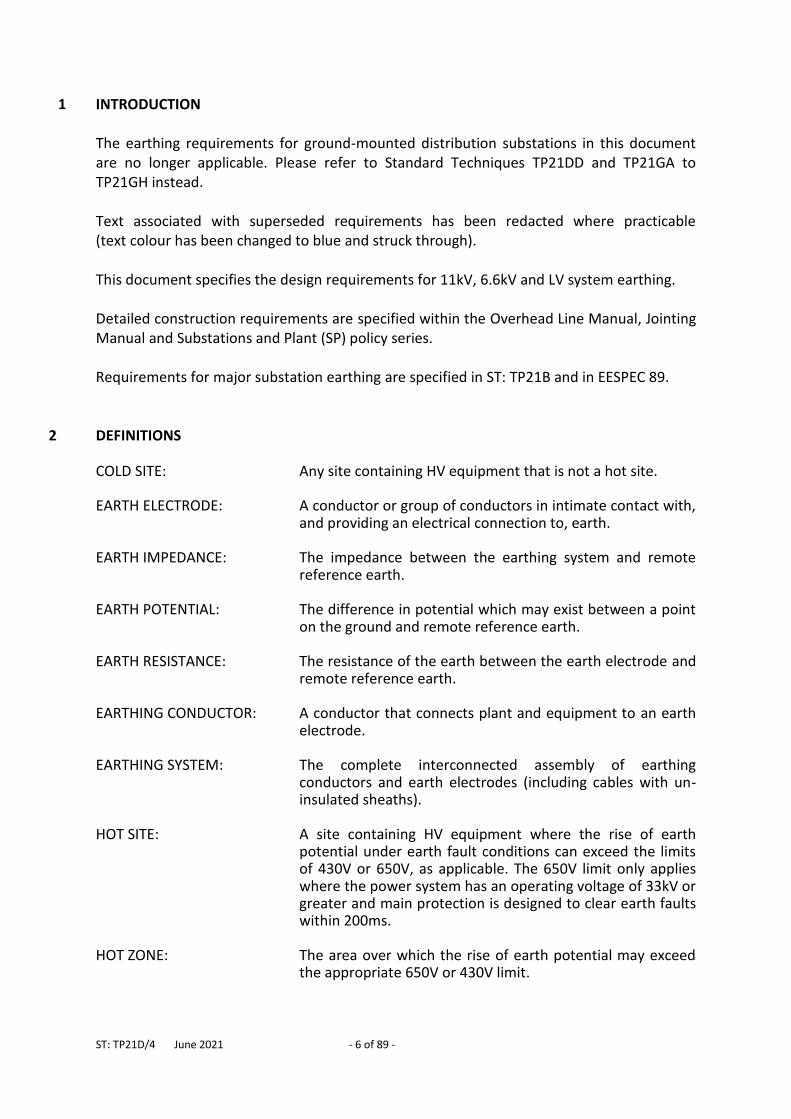
1 INTRODUCTION The earthing requirements for ground-mounted distribution substations in this document are no longer applicable. Please refer to Standard Techniques TP21DD and TP21GA to TP21GH instead. Text associated with superseded requirements has been redacted where practicable (text colour has been changed to blue and struck through). This document specifies the design requirements for 11kV, 6.6kV and LV system earthing. Detailed construction requirements are specified within the Overhead Line Manual, Jointing Manual and Substations and Plant (SP) policy series. Requirements for major substation earthing are specified in ST: TP21B and in EESPEC 89.
2 DEFINITIONS COLD SITE: Any site containing HV equipment that is not a hot site. EARTH ELECTRODE: A conductor or group of conductors in intimate contact with,
and providing an electrical connection to, earth. EARTH IMPEDANCE: The impedance between the earthing system and remote
reference earth. EARTH POTENTIAL: The difference in potential which may exist between a point
on the ground and remote reference earth. EARTH RESISTANCE: The resistance of the earth between the earth electrode and
remote reference earth. EARTHING CONDUCTOR: A conductor that connects plant and equipment to an earth
electrode.
EARTHING SYSTEM: The complete interconnected assembly of earthing conductors and earth electrodes (including cables with un-insulated sheaths).
HOT SITE: A site containing HV equipment where the rise of earth
potential under earth fault conditions can exceed the limits of 430V or 650V, as applicable. The 650V limit only applies where the power system has an operating voltage of 33kV or greater and main protection is designed to clear earth faults within 200ms.
HOT ZONE: The area over which the rise of earth potential may exceed
the appropriate 650V or 430V limit.
ST: TP21D/4 June 2021 - 7 of 89 -
PME EARTH An earth electrode installed and connected to the LV neutral which helps to control the voltage that may appear on the neutral/earth conductor, should it become damaged or broken.
STEP VOLTAGE: The potential difference between two points on the surface
of the soil which are 1m apart.
TOUCH VOLTAGE Voltage appearing during an insulation fault, between simultaneously accessible parts; hand-to-foot or hand-to-hand.
3 GENERAL REQUIREMENTS Plant and equipment shall be adequately earthed in order to: satisfy statutory requirements.
minimise the risk to staff and the general public from hazardous potentials.
allow protection systems to detect and to remove earth faults from the network quickly and decisively and to minimise the number of customers affected by such fault.
minimise equipment damage from lightning and power system faults.
3.1 Statutory Requirements The Electricity Safety, Quality and Continuity Regulations 2002 (ESQCR) include a number of clauses related to earthing. A summary of these clauses is given below:
3.1.1 General Regulation 8(1) requires Distributors to connect their networks to earth and ensure they remain connected to earth, so far as reasonably practicable, during fault conditions. Regulation 10 requires Distributors to earth any metalwork not intended to operate as a phase conductor, that encloses, supports or is otherwise associated with equipment in their network, where necessary to prevent danger. This requirement is waived for metalwork associated with wood pole lines (where the metalwork is at least 3m above the ground) and for wall mounted metal brackets used to support overhead lines, where the line is supported by an insulator and the conductor that is in contact with the insulator is insulated. Regulation 8(4) prevents Consumers combining neutral and earthing functions in a single conductor. Regulation 8(3)(a) requires the outer conductor of any cable (or overhead line) consisting of concentric conductors to be connected to earth.
3.1.2 HV System Requirements Regulation 8(2)(a) requires distributors to connect their HV network to earth at, or as close as is reasonably practicable to, the source of voltage. Where there is more than one source of voltage the connection to earth only has to be made at one point.
ST: TP21D/4 June 2021 - 8 of 89 -
Regulation 8(2)(b) requires earth electrodes to be designed, installed and used to prevent danger occurring in any LV network as a result of a fault occurring in the HV network. Regulation 8(2)(c) requires an alarm to be provided to warn the distributor when a fault is held on an arc suppression coil (Peterson coil).
3.1.3 LV System Requirements Regulation 8(3)(b) requires every supply neutral conductor to be connected to earth at, or as near as is reasonably practicable, to the source of voltage except where connections are only made at one point on that network to a single source of voltage, in which case the earth connection can be made at the point of connection or at another point closer to the source of voltage. Regulation 8(3)(c) specifies that no impedance may be inserted in any connection to earth except where this is required for the operation of switching devices, instruments, or equipment for control, telemetry or metering. Regulation 9 specifies that, where a Distributor combines neutral and earthing functions within a single conductor (e.g. PME) or where the arrangement allowed under Regulation 8(3)(b) is used:
The supply neutral conductor shall be connected to earth at a point no closer to the source of voltage than the most remote point beyond which 4 or more consumers are connected (of which one or more is provided with PME).
The supply neutral conductor shall be connected to earth at other points as necessary to prevent danger arising from a broken supply neutral conductor.
An earth terminal shall not be made available for a connection to a caravan or boat.
3.1.4 Earthing of Metalwork Regulation 10 requires all metalwork enclosing, supporting or otherwise associated with generation equipment, distribution equipment or transmission equipment (except phase conductors) to be connected to earth, where this is necessary to prevent danger. Metalwork which is attached to a wood pole that is designed and constructed so as to prevent, as reasonably practicable, danger within 3m of the ground, does not need to be earthed. Wall mounted metal brackets which support overhead lines via insulators, do not need to be earthed, where the overhead lines (i.e. the conductors) are also insulated.
3.2 Hazardous Potentials Any exposed conductor associated with network equipment metalwork that is not a phase conductor and that could be electrically energised must be earthed if it would otherwise create a hazard to people or to animals. Examples include:
Cable screens and armouring Metal conduits Metal cabinets and enclosures Frames of motors, generators, transformers, switchgear Substation fencing Pipes
ST: TP21D/4 June 2021 - 9 of 89 -
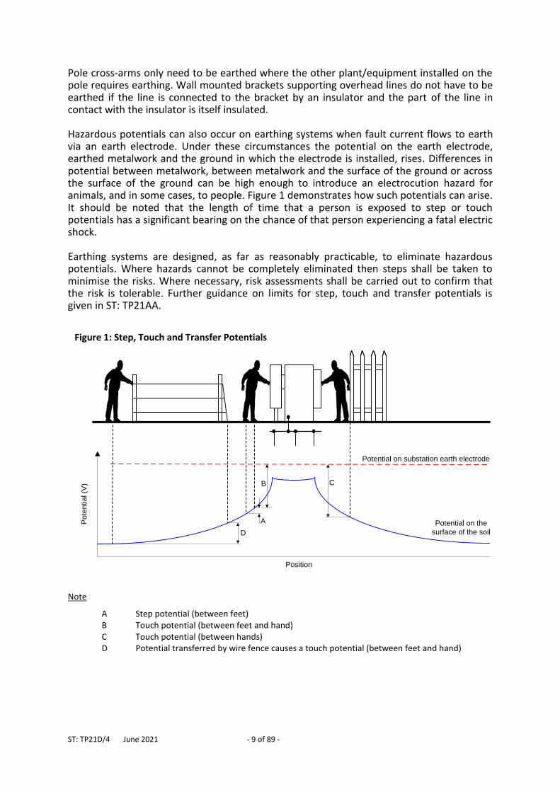
Pole cross-arms only need to be earthed where the other plant/equipment installed on the pole requires earthing. Wall mounted brackets supporting overhead lines do not have to be earthed if the line is connected to the bracket by an insulator and the part of the line in contact with the insulator is itself insulated. Hazardous potentials can also occur on earthing systems when fault current flows to earth via an earth electrode. Under these circumstances the potential on the earth electrode, earthed metalwork and the ground in which the electrode is installed, rises. Differences in potential between metalwork, between metalwork and the surface of the ground or across the surface of the ground can be high enough to introduce an electrocution hazard for animals, and in some cases, to people. Figure 1 demonstrates how such potentials can arise. It should be noted that the length of time that a person is exposed to step or touch potentials has a significant bearing on the chance of that person experiencing a fatal electric shock. Earthing systems are designed, as far as reasonably practicable, to eliminate hazardous potentials. Where hazards cannot be completely eliminated then steps shall be taken to minimise the risks. Where necessary, risk assessments shall be carried out to confirm that the risk is tolerable. Further guidance on limits for step, touch and transfer potentials is given in ST: TP21AA.
Note
A Step potential (between feet) B Touch potential (between feet and hand) C Touch potential (between hands) D Potential transferred by wire fence causes a touch potential (between feet and hand)
Figure 1: Step, Touch and Transfer Potentials
D
A
B C
Po
ten
tia
l (V
)
Position
Potential on the
surface of the soil
Potential on substation earth electrode
ST: TP21D/4 June 2021 - 10 of 89 -
3.3 Fault Clearance The resistance of 11kV and 6.6kV earthing systems restrict available earth fault current. This is particularly relevant where an earth fault occurs on equipment fed via 11kV or 6.6kV overhead line, since standard lines do not include an earth wire. Fault current is forced to flow through the local earthing system to return to the source substation. In these circumstances a 20 ohm earth electrode, for example, will restrict 11kV earth fault current to less than 317A (ignoring other system impedances). The resistance of the earthing system must be low enough to allow protection relays and fuses to detect fault current, discriminate with other protection and disconnect the fault quickly. Lowering the earth resistance also reduces, to some extent, the rise of earth potential at that location during earth faults. Also, the higher the earth fault current, the faster protection systems operate.
3.4 Over-voltage Protection
3.4.1 Lightning Impulses
Lighting impulses on WPD's network can cause damage to equipment (electrical plant, insulators, cables etc.). HV over-voltage protection devices (e.g. arc gaps, surge arresters etc.) are installed on 11kV and 6.6kV systems to help protect equipment from lightning. The attenuation of lightning impulses and the performance of over voltage protection is greatly improved by well designed, low impedance earthing systems. Earthing conductor associated with surge arresters and triggered arc gaps should, as far as possible, provide a straight path for current to flow into the ground. Every bend increases the inductance of the earthing conductor which, in turn, gives rise to high impedance for high frequency impulses, such as lightning. In addition, for high frequency impulses, the vast majority of current flows into the ground via earth electrode installed within just a few meters of the equipment and electrode installed further away has little impact. In order to minimise voltage rise caused by lightning it is necessary to make use of both vertical and horizontal earth electrode installed close to the equipment.
4 ELECTRODE DESIGN
4.1 Maximum Resistance
4.1.1 11kV and 6.6kV
The resistance of 11kV and 6.6kV earthing systems shall, as far as reasonably practicable, be no higher than:
20 ohms for 11kV earthing systems.
15 ohms for 6.6kV earthing systems.
ST: TP21D/4 June 2021 - 11 of 89 -
It is recognised that at some sites with particularly high soil resistivity it may not be reasonably practicable to satisfy the above criteria. This is deemed to be the case where the electrode extends for a distance of 200m or more from the installation without reaching the required resistance. In such cases an earth resistance of up to 40 ohms may be accepted as long as the equipment is protected by sensitive earth fault (SEF) protection. In Peterson Coil earthed systems the SEF protection only has to be in service when the Peterson Coil is shorted.
4.1.2 Low Voltage (LV) LV Earthing Systems The resistance of LV earthing systems shall be:
No higher than the maximum allowable resistance for the associated HV earthing system (see 4.1.1) and;
No higher than 20 ohms where PME or PNB earth terminals are to be made available.
PME Earth Electrodes The earth resistance of individual PME earth electrodes shall be 100 ohms or less.
4.2 Thermal Requirements As fault current flows through earth conductor and electrode into the ground it heats the conductor and dries out the soil around the electrode (increasing earth resistance). The conductor itself must be capable of withstanding this flow of current without damage and the surface area of the earth electrode must be large enough to prevent the ground drying out appreciably.
4.2.1 Conductor Fault Ratings The method for calculating fault ratings of earth conductors is specified in 7.1. In practice, standard earthing system designs described below are suitable as long as the following minimum conductor sizes are used:
35mm2 Copper PVC/PVC
70mm2 Copper (bare electrode)
25mm x 3mm (bare earth strip)
12.5mm diameter copper clad steel earth rods
15mm diameter copper earth rods
ST: TP21D/4 June 2021 - 12 of 89 -
It should be noted that bare earth electrode with a cross-sectional area of at least 70mm2 is specified to provide sufficient surface area in contact with the ground, not for fault rating requirements (see 4.2.2).
4.2.2 Surface Area Requirements The surface area of 11kV and 6.6kV earthing electrode in contact with the ground must be sufficiently large to prevent the ground drying out as fault current flows from the electrode into the ground. This prevents the resistance of the earthing system increasing unduly during the fault. Further information on calculating the required surface area is included in 7.1. Where equipment is connected to an HV cable system and there is a continuous path for earth fault current to flow (i.e. down cable sheaths) all the way back to the primary substation only a small proportion of earth fault current will flow into the ground via the earth electrode. In such cases the surface area requirement is automatically satisfied by all the standard electrodes described in Table 3. Where equipment is connected via an overhead line (with no earth wire) there is no continuous metallic path for earth fault current to flow back to the primary substation. In these circumstances the surface area requirements often dictate the length and arrangement for the electrode (see 4.4.2).
4.3 Location of Earth Electrode
Earth electrode shall be located and designed to:
minimise risk from step, touch and transfer potentials.
minimise likelihood of subsequent damage to the earthing system.
make use of lower resistivity soil.
make use of softer ground that will ease installation. Bare earth electrode shall, as far as possible, not be laid in areas where people may reasonably be barefoot (e.g. near swimming pools, across caravan sites and gardens etc.). 11kV and 6.6kV earth electrode shall be segregated by at least:
9m from Swimming pools (and other areas where people may reasonably be barefoot).
9m from ponds/lakes used for commercial fish farming.
10m from BT telephone exchanges.
10m from railway installations.
9m from LV earth electrode, buildings and buried metalwork (e.g. lightning rods), where the 11kV or 6.6kV electrode is associated with a hot site.
ST: TP21D/4 June 2021 - 13 of 89 -
Similarly, LV earth electrode and individual PME earth electrodes shall be segregated by at least:
10m from overhead line towers (pylons).
9m from HV earth electrode.
9m from hessian sheathed HV cables or from earth electrode bonded to an HV cable sheath (sometimes carried out at an HV joint) where the cable is connected to a hot site.
Segregation is achieved either by physically burying the LV electrode away from the HV equipment / installation or by using PVC (or equivalent) insulated conductor in the areas where the above distances are infringed. In practice, these requirements can severely restrict location of earthed HV equipment. For example, hot substations cannot normally be installed within 9m of a steel framed building.
4.4 Standard Earth Electrode Arrangements
4.4.1 Individual PME Earth Electrodes
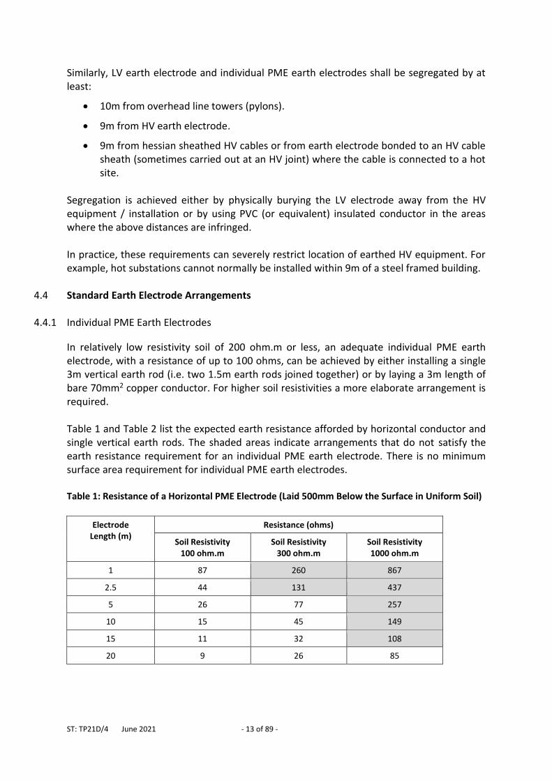
In relatively low resistivity soil of 200 ohm.m or less, an adequate individual PME earth electrode, with a resistance of up to 100 ohms, can be achieved by either installing a single 3m vertical earth rod (i.e. two 1.5m earth rods joined together) or by laying a 3m length of bare 70mm2 copper conductor. For higher soil resistivities a more elaborate arrangement is required. Table 1 and Table 2 list the expected earth resistance afforded by horizontal conductor and single vertical earth rods. The shaded areas indicate arrangements that do not satisfy the earth resistance requirement for an individual PME earth electrode. There is no minimum surface area requirement for individual PME earth electrodes. Table 1: Resistance of a Horizontal PME Electrode (Laid 500mm Below the Surface in Uniform Soil)
Electrode Length (m)
Resistance (ohms)
Soil Resistivity 100 ohm.m
Soil Resistivity 300 ohm.m
Soil Resistivity 1000 ohm.m
1 87 260 867
2.5 44 131 437
5 26 77 257
10 15 45 149
15 11 32 108
20 9 26 85
ST: TP21D/4 June 2021 - 14 of 89 -
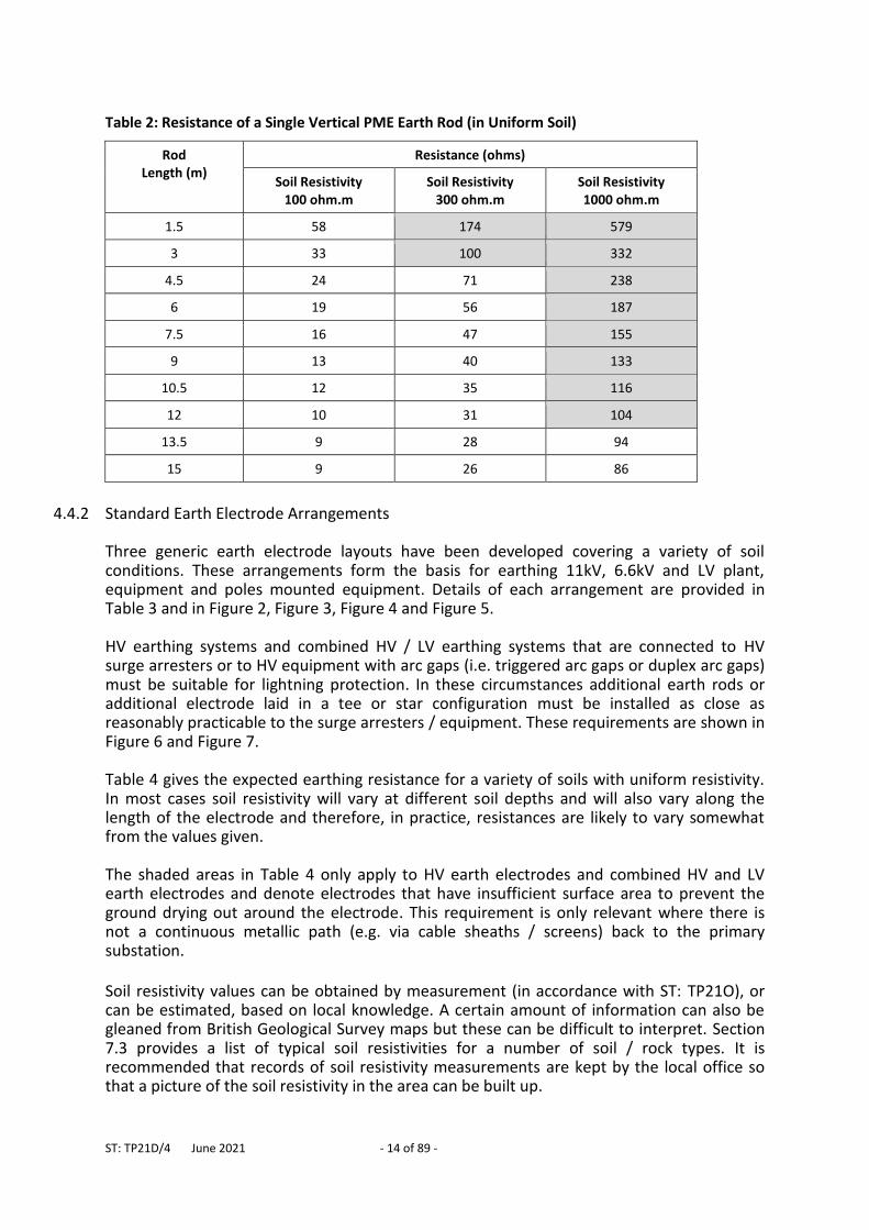
Table 2: Resistance of a Single Vertical PME Earth Rod (in Uniform Soil)
Rod Length (m)
Resistance (ohms)
Soil Resistivity 100 ohm.m
Soil Resistivity 300 ohm.m
Soil Resistivity 1000 ohm.m
1.5 58 174 579
3 33 100 332
4.5 24 71 238
6 19 56 187
7.5 16 47 155
9 13 40 133
10.5 12 35 116
12 10 31 104
13.5 9 28 94
15 9 26 86
4.4.2 Standard Earth Electrode Arrangements
Three generic earth electrode layouts have been developed covering a variety of soil conditions. These arrangements form the basis for earthing 11kV, 6.6kV and LV plant, equipment and poles mounted equipment. Details of each arrangement are provided in Table 3 and in Figure 2, Figure 3, Figure 4 and Figure 5. HV earthing systems and combined HV / LV earthing systems that are connected to HV surge arresters or to HV equipment with arc gaps (i.e. triggered arc gaps or duplex arc gaps) must be suitable for lightning protection. In these circumstances additional earth rods or additional electrode laid in a tee or star configuration must be installed as close as reasonably practicable to the surge arresters / equipment. These requirements are shown in Figure 6 and Figure 7. Table 4 gives the expected earthing resistance for a variety of soils with uniform resistivity. In most cases soil resistivity will vary at different soil depths and will also vary along the length of the electrode and therefore, in practice, resistances are likely to vary somewhat from the values given. The shaded areas in Table 4 only apply to HV earth electrodes and combined HV and LV earth electrodes and denote electrodes that have insufficient surface area to prevent the ground drying out around the electrode. This requirement is only relevant where there is not a continuous metallic path (e.g. via cable sheaths / screens) back to the primary substation.
Soil resistivity values can be obtained by measurement (in accordance with ST: TP21O), or can be estimated, based on local knowledge. A certain amount of information can also be gleaned from British Geological Survey maps but these can be difficult to interpret. Section 7.3 provides a list of typical soil resistivities for a number of soil / rock types. It is recommended that records of soil resistivity measurements are kept by the local office so that a picture of the soil resistivity in the area can be built up.
ST: TP21D/4 June 2021 - 15 of 89 -
The Planner should select the required earthing arrangement and estimate the length of electrode to satisfy resistance and thermal requirements at the design stage (see 4.1 & 4.2). The electrode arrangement, required earth resistance and estimated minimum length requirements should be specified on construction drawings. Earth electrode resistance is proportional to soil resistivity (in uniform soil), and so, Table 4 can also be used during the construction phase to calculate the actual soil resistivity using the following formula:
estimated
actualestimated
actualR
Rρρ
ρactual = actual soil resistivity ρestimated = soil resistivity estimated at design stage Ractual = measured earth electrode resistance Restimated = earth electrode resistance estimated from Table 4
Where onerous conditions are found advice may be sought from Primary System Design who can, if necessary, carry out site-specific earthing designs.
ST: TP21D/4 June 2021 - 16 of 89 -
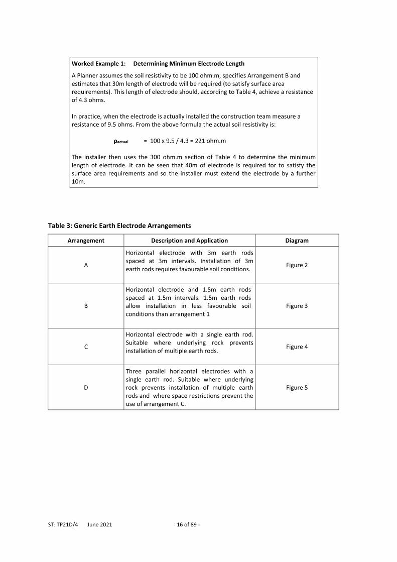
Worked Example 1: Determining Minimum Electrode Length
A Planner assumes the soil resistivity to be 100 ohm.m, specifies Arrangement B and estimates that 30m length of electrode will be required (to satisfy surface area requirements). This length of electrode should, according to Table 4, achieve a resistance of 4.3 ohms. In practice, when the electrode is actually installed the construction team measure a resistance of 9.5 ohms. From the above formula the actual soil resistivity is:
ρactual = 100 x 9.5 / 4.3 = 221 ohm.m
The installer then uses the 300 ohm.m section of Table 4 to determine the minimum length of electrode. It can be seen that 40m of electrode is required for to satisfy the surface area requirements and so the installer must extend the electrode by a further 10m.
Table 3: Generic Earth Electrode Arrangements
Arrangement Description and Application Diagram
A
Horizontal electrode with 3m earth rods spaced at 3m intervals. Installation of 3m earth rods requires favourable soil conditions.
Figure 2
B
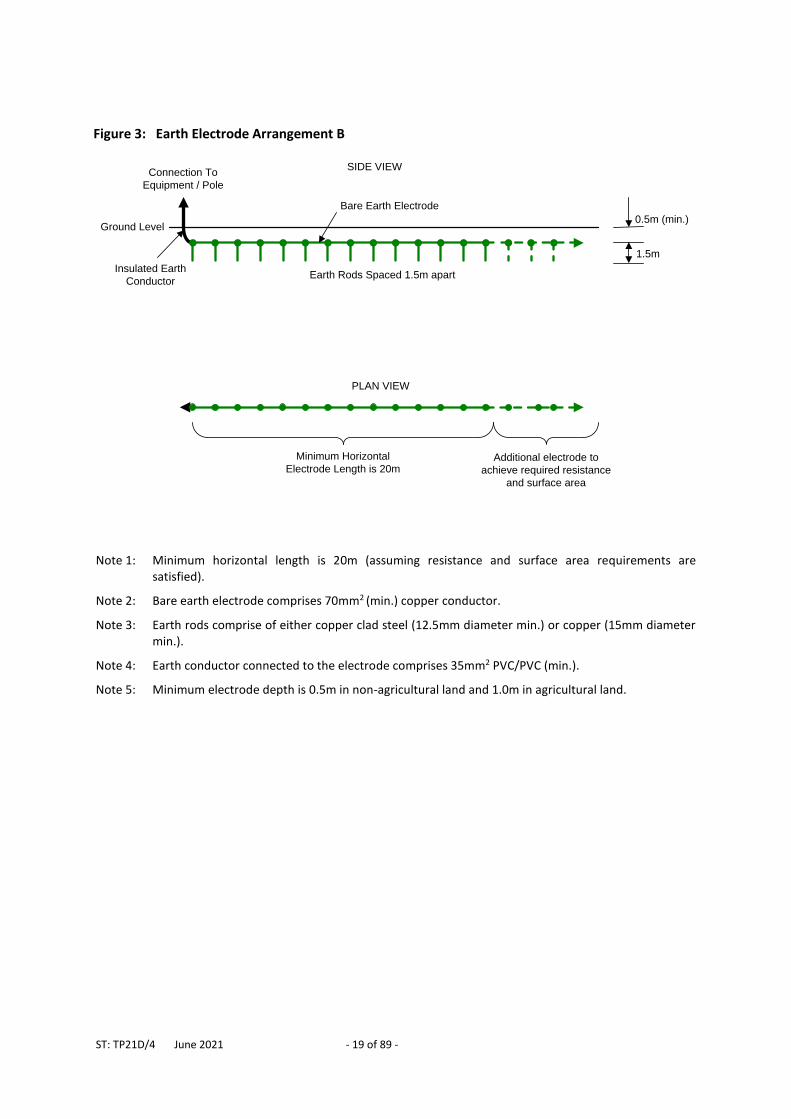
Horizontal electrode and 1.5m earth rods spaced at 1.5m intervals. 1.5m earth rods allow installation in less favourable soil conditions than arrangement 1
Figure 3
C
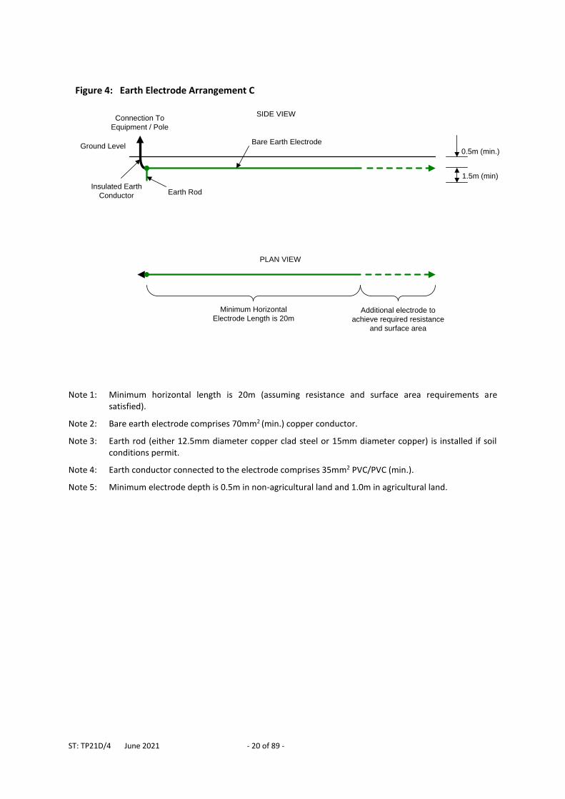
Horizontal electrode with a single earth rod. Suitable where underlying rock prevents installation of multiple earth rods.
Figure 4
D
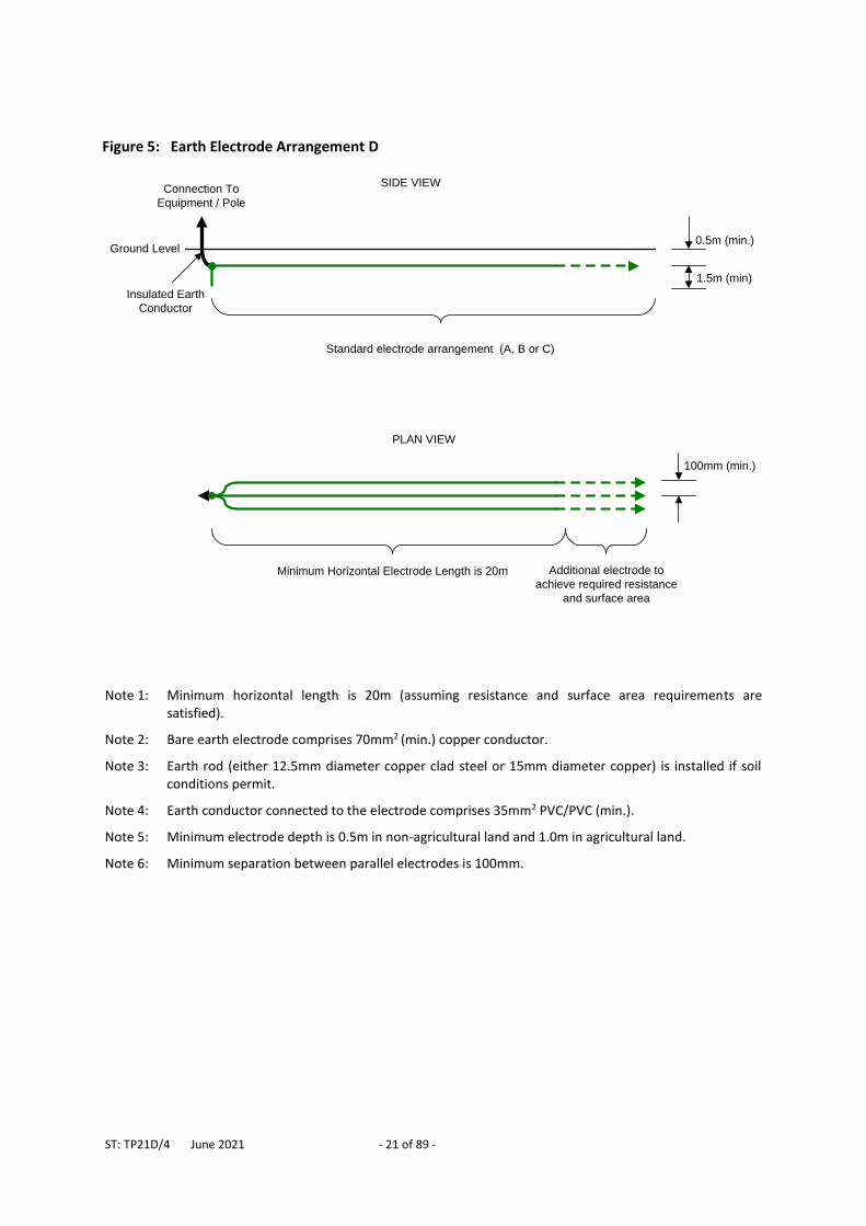
Three parallel horizontal electrodes with a single earth rod. Suitable where underlying rock prevents installation of multiple earth rods and where space restrictions prevent the use of arrangement C.
Figure 5
ST: TP21D/4 June 2021 - 17 of 89 -
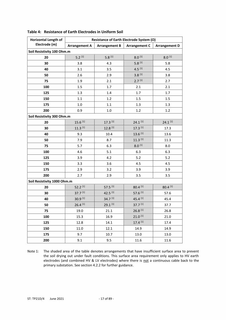
Table 4: Resistance of Earth Electrodes in Uniform Soil
Horizontal Length of Electrode (m)
Resistance of Earth Electrode System (Ω)
Arrangement A Arrangement B Arrangement C Arrangement D
Soil Resistivity 100 Ohm.m
20 5.2 [1] 5.8 [1] 8.0 [1] 8.0 [1]
30 3.8 4.3 5.8 [1] 5.8
40 3.1 3.5 4.5 [1] 4.5
50 2.6 2.9 3.8 [1] 3.8
75 1.9 2.1 2.7 [1] 2.7
100 1.5 1.7 2.1 2.1
125 1.3 1.4 1.7 1.7
150 1.1 1.2 1.5 1.5
175 1.0 1.1 1.3 1.3
200 0.9 1.0 1.2 1.2
Soil Resistivity 300 Ohm.m
20 15.6 [1] 17.3 [1] 24.1 [1] 24.1 [1]
30 11.3 [1] 12.8 [1] 17.3 [1] 17.3
40 9.3 10.4 13.6 [1] 13.6
50 7.9 8.7 11.3 [1] 11.3
75 5.7 6.3 8.0 [1] 8.0
100 4.6 5.1 6.3 6.3
125 3.9 4.2 5.2 5.2
150 3.3 3.6 4.5 4.5
175 2.9 3.2 3.9 3.9
200 2.7 2.9 3.5 3.5
Soil Resistivity 1000 Ohm.m
20 52.2 [1] 57.5 [1] 80.4 [1] 80.4 [1]
30 37.7 [1] 42.5 [1] 57.6 [1] 57.6
40 30.9 [1] 34.7 [1] 45.4 [1] 45.4
50 26.4 [1] 29.1 [1] 37.7 [1] 37.7
75 19.0 21.1 26.8 [1] 26.8
100 15.3 16.9 21.0 [1] 21.0
125 12.8 14.1 17.4 [1] 17.4
150 11.0 12.1 14.9 14.9
175 9.7 10.7 13.0 13.0
200 9.1 9.5 11.6 11.6
Note 1: The shaded area of the table denotes arrangements that have insufficient surface area to prevent
the soil drying out under fault conditions. This surface area requirement only applies to HV earth electrodes (and combined HV & LV electrodes) where there is not a continuous cable back to the primary substation. See section 4.2.2 for further guidance.
ST: TP21D/4 June 2021 - 18 of 89 -
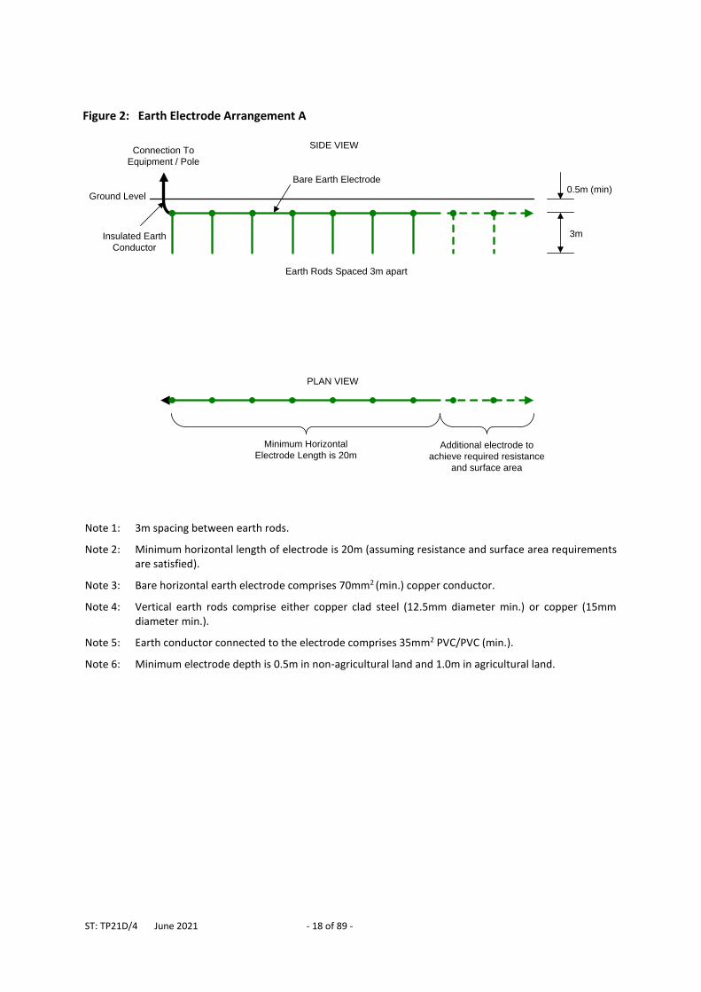
Note 1: 3m spacing between earth rods.
Note 2: Minimum horizontal length of electrode is 20m (assuming resistance and surface area requirements are satisfied).
Note 3: Bare horizontal earth electrode comprises 70mm2 (min.) copper conductor.
Note 4: Vertical earth rods comprise either copper clad steel (12.5mm diameter min.) or copper (15mm diameter min.).
Note 5: Earth conductor connected to the electrode comprises 35mm2 PVC/PVC (min.).
Note 6: Minimum electrode depth is 0.5m in non-agricultural land and 1.0m in agricultural land.
Figure 2: Earth Electrode Arrangement A
0.5m (min)
3m
Ground Level
Insulated Earth
Conductor
SIDE VIEWConnection To
Equipment / Pole
Additional electrode to
achieve required resistance
and surface area
Minimum Horizontal
Electrode Length is 20m
PLAN VIEW
Earth Rods Spaced 3m apart
Bare Earth Electrode
ST: TP21D/4 June 2021 - 19 of 89 -
Note 1: Minimum horizontal length is 20m (assuming resistance and surface area requirements are satisfied).
Note 2: Bare earth electrode comprises 70mm2 (min.) copper conductor.
Note 3: Earth rods comprise of either copper clad steel (12.5mm diameter min.) or copper (15mm diameter min.).
Note 4: Earth conductor connected to the electrode comprises 35mm2 PVC/PVC (min.).
Note 5: Minimum electrode depth is 0.5m in non-agricultural land and 1.0m in agricultural land.
Figure 3: Earth Electrode Arrangement B
0.5m (min.)
1.5m
Ground Level
Insulated Earth
Conductor
Bare Earth Electrode
SIDE VIEWConnection To
Equipment / Pole
Additional electrode to
achieve required resistance
and surface area
Minimum Horizontal
Electrode Length is 20m
PLAN VIEW
Earth Rods Spaced 1.5m apart
ST: TP21D/4 June 2021 - 20 of 89 -
Note 1: Minimum horizontal length is 20m (assuming resistance and surface area requirements are satisfied).
Note 2: Bare earth electrode comprises 70mm2 (min.) copper conductor.
Note 3: Earth rod (either 12.5mm diameter copper clad steel or 15mm diameter copper) is installed if soil conditions permit.
Note 4: Earth conductor connected to the electrode comprises 35mm2 PVC/PVC (min.).
Note 5: Minimum electrode depth is 0.5m in non-agricultural land and 1.0m in agricultural land.
Figure 4: Earth Electrode Arrangement C
1.5m (min)
Ground Level
Insulated Earth
Conductor
SIDE VIEWConnection To
Equipment / Pole
Additional electrode to
achieve required resistance
and surface area
Minimum Horizontal
Electrode Length is 20m
PLAN VIEW
0.5m (min.)
Bare Earth Electrode
Earth Rod
ST: TP21D/4 June 2021 - 21 of 89 -
Note 1: Minimum horizontal length is 20m (assuming resistance and surface area requirements are satisfied).
Note 2: Bare earth electrode comprises 70mm2 (min.) copper conductor.
Note 3: Earth rod (either 12.5mm diameter copper clad steel or 15mm diameter copper) is installed if soil conditions permit.
Note 4: Earth conductor connected to the electrode comprises 35mm2 PVC/PVC (min.).
Note 5: Minimum electrode depth is 0.5m in non-agricultural land and 1.0m in agricultural land.
Note 6: Minimum separation between parallel electrodes is 100mm.
Figure 5: Earth Electrode Arrangement D
PLAN VIEW
1.5m (min)
Ground Level
Insulated Earth
Conductor
SIDE VIEWConnection To
Equipment / Pole
0.5m (min.)
Minimum Horizontal Electrode Length is 20m Additional electrode to
achieve required resistance
and surface area
Standard electrode arrangement (A, B or C)
100mm (min.)
ST: TP21D/4 June 2021 - 22 of 89 -
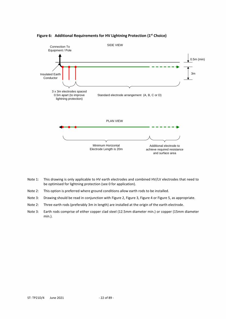
Note 1: This drawing is only applicable to HV earth electrodes and combined HV/LV electrodes that need to be optimised for lightning protection (see 0 for application).
Note 2: This option is preferred where ground conditions allow earth rods to be installed.
Note 3: Drawing should be read in conjunction with Figure 2, Figure 3, Figure 4 or Figure 5, as appropriate.
Note 2: Three earth rods (preferably 3m in length) are installed at the origin of the earth electrode.
Note 3: Earth rods comprise of either copper clad steel (12.5mm diameter min.) or copper (15mm diameter min.).
Figure 6: Additional Requirements for HV Lightning Protection (1st Choice)
0.5m (min)
3mInsulated Earth
Conductor
SIDE VIEWConnection To
Equipment / Pole
PLAN VIEW
Standard electrode arrangement (A, B, C or D)
3 x 3m electrodes spaced
0.5m apart (to improve
lightning protection)
Additional electrode to
achieve required resistance
and surface area
Minimum Horizontal
Electrode Length is 20m
ST: TP21D/4 June 2021 - 23 of 89 -
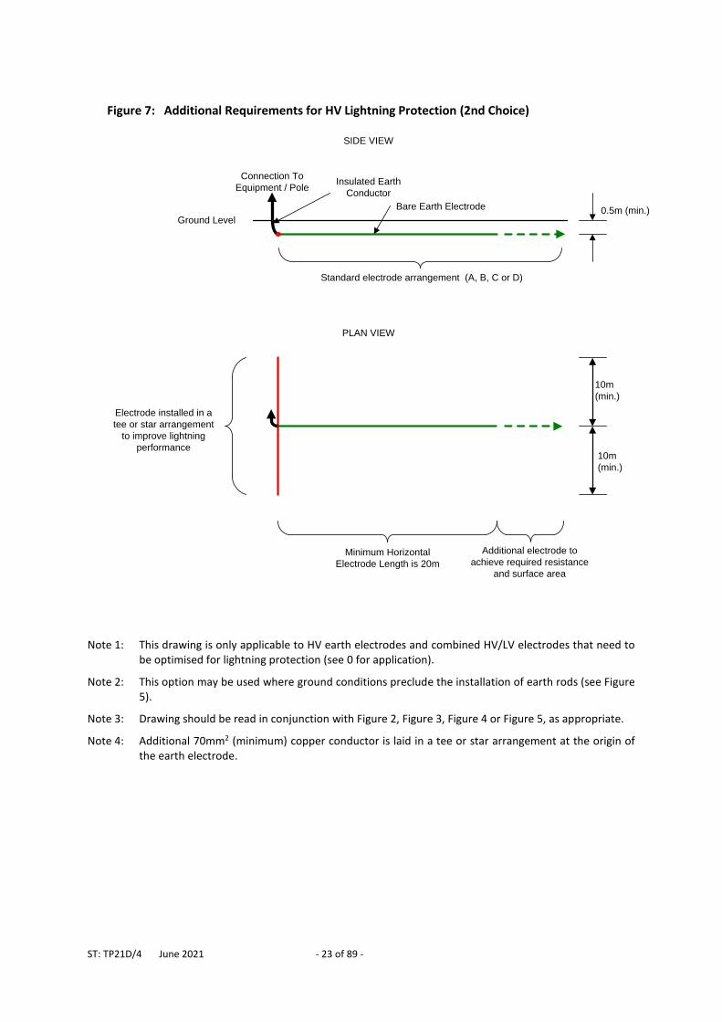
Note 1: This drawing is only applicable to HV earth electrodes and combined HV/LV electrodes that need to be optimised for lightning protection (see 0 for application).
Note 2: This option may be used where ground conditions preclude the installation of earth rods (see Figure 5).
Note 3: Drawing should be read in conjunction with Figure 2, Figure 3, Figure 4 or Figure 5, as appropriate.
Note 4: Additional 70mm2 (minimum) copper conductor is laid in a tee or star arrangement at the origin of the earth electrode.
Figure 7: Additional Requirements for HV Lightning Protection (2nd Choice)
Ground Level
Insulated Earth
Conductor
Bare Earth Electrode
SIDE VIEW
Connection To
Equipment / Pole
Electrode installed in a
tee or star arrangement
to improve lightning
performance
PLAN VIEW
10m
(min.)
10m
(min.)
0.5m (min.)
Standard electrode arrangement (A, B, C or D)
Additional electrode to
achieve required resistance
and surface area
Minimum Horizontal
Electrode Length is 20m
ST: TP21D/4 June 2021 - 24 of 89 -
5 11KV AND 6.6KV EARTHING
5.1 System Earthing
Western Power Distribution’s 11kV and 6.6kV systems are earthed exclusively at source primary substations and protection systems are designed and set accordingly. The only exception to this rule is the earthing of 5 limb VTs, as described below. 11kV and 6.6kV customer systems shall not introduce additional earths to Western Power Distribution’s 11kV and 6.6kV system. 5 limb voltage transformers (VTs), typically used for protection such as neutral voltage displacement, directional earth fault or distance protection, must have their HV winding earthed in order to function correctly. They inherently have a high impedance and so do not significantly affect the flow of current under earth fault conditions.
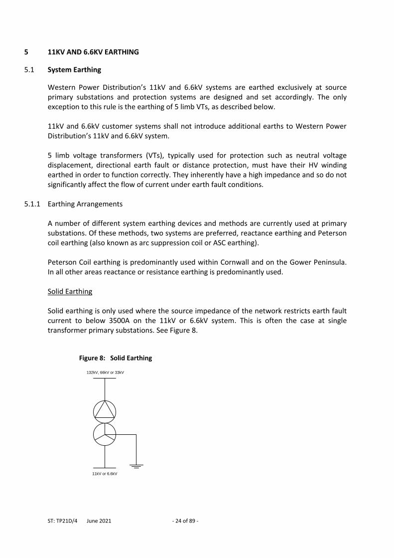
5.1.1 Earthing Arrangements A number of different system earthing devices and methods are currently used at primary substations. Of these methods, two systems are preferred, reactance earthing and Peterson coil earthing (also known as arc suppression coil or ASC earthing). Peterson Coil earthing is predominantly used within Cornwall and on the Gower Peninsula. In all other areas reactance or resistance earthing is predominantly used. Solid Earthing Solid earthing is only used where the source impedance of the network restricts earth fault current to below 3500A on the 11kV or 6.6kV system. This is often the case at single transformer primary substations. See Figure 8.
Figure 8: Solid Earthing
11kV or 6.6kV
132kV, 66kV or 33kV
ST: TP21D/4 June 2021 - 25 of 89 -
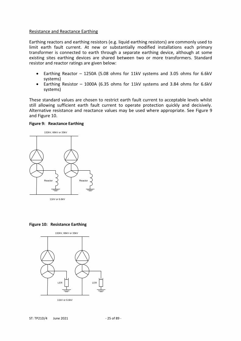
Resistance and Reactance Earthing Earthing reactors and earthing resistors (e.g. liquid earthing resistors) are commonly used to limit earth fault current. At new or substantially modified installations each primary transformer is connected to earth through a separate earthing device, although at some existing sites earthing devices are shared between two or more transformers. Standard resistor and reactor ratings are given below:
Earthing Reactor – 1250A (5.08 ohms for 11kV systems and 3.05 ohms for 6.6kV systems)
Earthing Resistor – 1000A (6.35 ohms for 11kV systems and 3.84 ohms for 6.6kV systems)
These standard values are chosen to restrict earth fault current to acceptable levels whilst still allowing sufficient earth fault current to operate protection quickly and decisively. Alternative resistance and reactance values may be used where appropriate. See Figure 9 and Figure 10.
Figure 9: Reactance Earthing
11kV or 6.6kV
132kV, 66kV or 33kV
Reactor Reactor
Figure 10: Resistance Earthing
11kV or 6.6kV
132kV, 66kV or 33kV
LER LER
ST: TP21D/4 June 2021 - 26 of 89 -
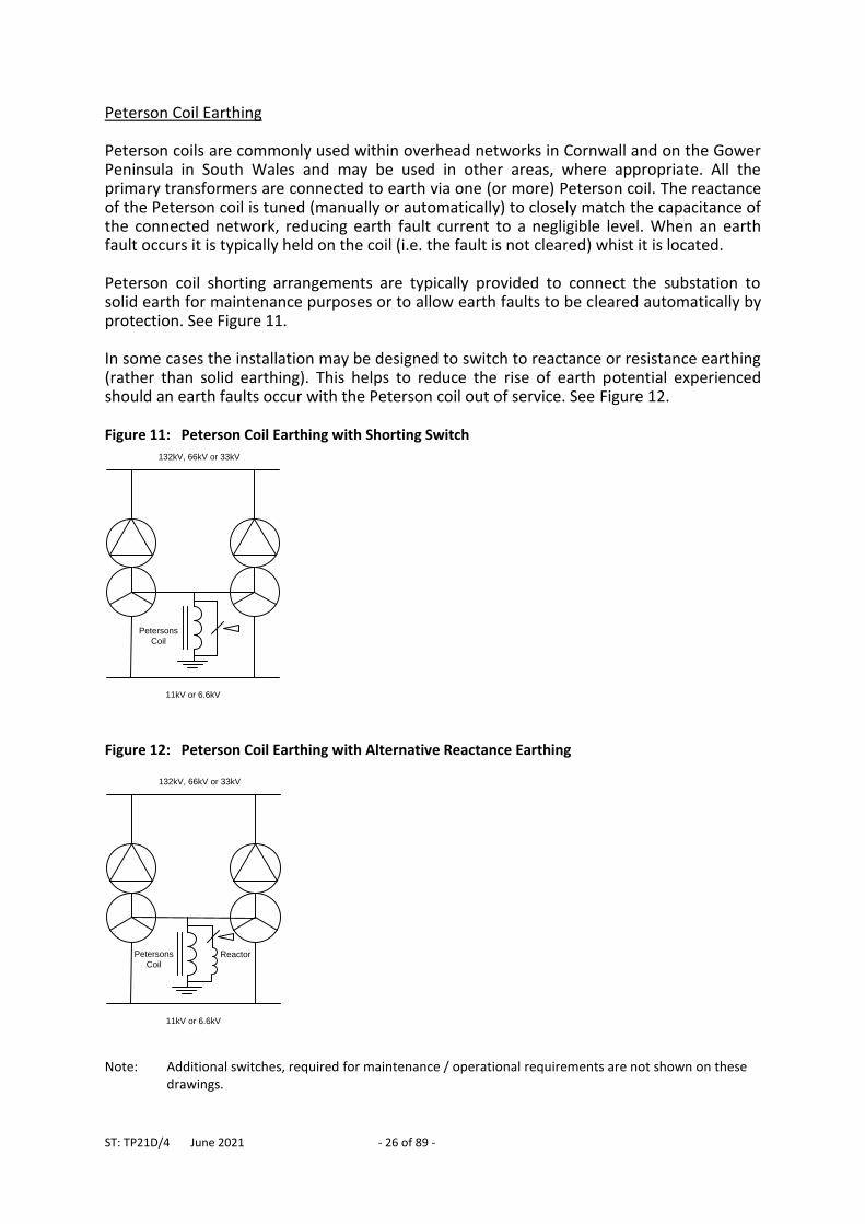
Peterson Coil Earthing Peterson coils are commonly used within overhead networks in Cornwall and on the Gower Peninsula in South Wales and may be used in other areas, where appropriate. All the primary transformers are connected to earth via one (or more) Peterson coil. The reactance of the Peterson coil is tuned (manually or automatically) to closely match the capacitance of the connected network, reducing earth fault current to a negligible level. When an earth fault occurs it is typically held on the coil (i.e. the fault is not cleared) whist it is located. Peterson coil shorting arrangements are typically provided to connect the substation to solid earth for maintenance purposes or to allow earth faults to be cleared automatically by protection. See Figure 11. In some cases the installation may be designed to switch to reactance or resistance earthing (rather than solid earthing). This helps to reduce the rise of earth potential experienced should an earth faults occur with the Peterson coil out of service. See Figure 12. Figure 11: Peterson Coil Earthing with Shorting Switch
11kV or 6.6kV
132kV, 66kV or 33kV
Petersons
Coil
Figure 12: Peterson Coil Earthing with Alternative Reactance Earthing
11kV or 6.6kV
132kV, 66kV or 33kV
Petersons
CoilReactor
Note: Additional switches, required for maintenance / operational requirements are not shown on these
drawings.
ST: TP21D/4 June 2021 - 27 of 89 -
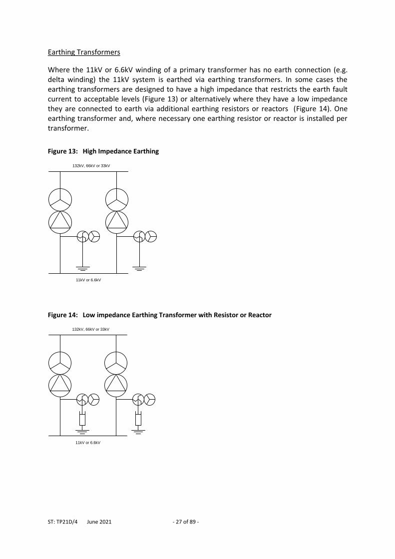
Earthing Transformers
Where the 11kV or 6.6kV winding of a primary transformer has no earth connection (e.g. delta winding) the 11kV system is earthed via earthing transformers. In some cases the earthing transformers are designed to have a high impedance that restricts the earth fault current to acceptable levels (Figure 13) or alternatively where they have a low impedance they are connected to earth via additional earthing resistors or reactors (Figure 14). One earthing transformer and, where necessary one earthing resistor or reactor is installed per transformer.
Figure 13: High Impedance Earthing
11kV or 6.6kV
132kV, 66kV or 33kV
Figure 14: Low impedance Earthing Transformer with Resistor or Reactor
132kV, 66kV or 33kV
11kV or 6.6kV
ST: TP21D/4 June 2021 - 28 of 89 -
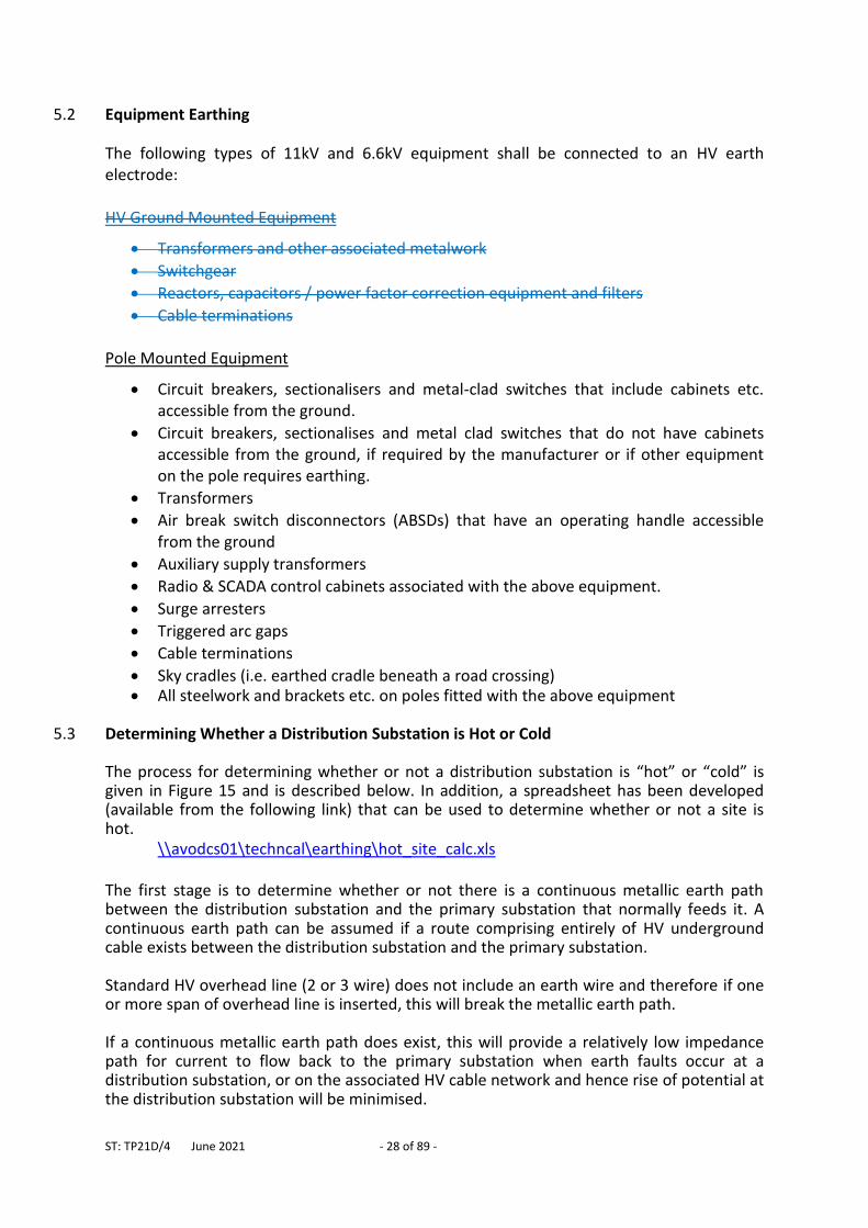
5.2 Equipment Earthing
The following types of 11kV and 6.6kV equipment shall be connected to an HV earth electrode: HV Ground Mounted Equipment
Transformers and other associated metalwork
Switchgear
Reactors, capacitors / power factor correction equipment and filters
Cable terminations Pole Mounted Equipment
Circuit breakers, sectionalisers and metal-clad switches that include cabinets etc. accessible from the ground.
Circuit breakers, sectionalises and metal clad switches that do not have cabinets accessible from the ground, if required by the manufacturer or if other equipment on the pole requires earthing.
Transformers
Air break switch disconnectors (ABSDs) that have an operating handle accessible from the ground
Auxiliary supply transformers
Radio & SCADA control cabinets associated with the above equipment.
Surge arresters
Triggered arc gaps
Cable terminations
Sky cradles (i.e. earthed cradle beneath a road crossing) All steelwork and brackets etc. on poles fitted with the above equipment
5.3 Determining Whether a Distribution Substation is Hot or Cold
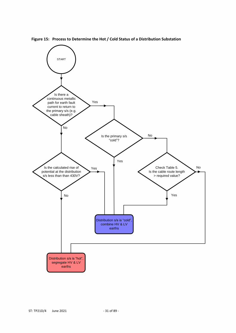
The process for determining whether or not a distribution substation is “hot” or “cold” is given in Figure 15 and is described below. In addition, a spreadsheet has been developed (available from the following link) that can be used to determine whether or not a site is hot.
\\avodcs01\techncal\earthing\hot_site_calc.xls The first stage is to determine whether or not there is a continuous metallic earth path between the distribution substation and the primary substation that normally feeds it. A continuous earth path can be assumed if a route comprising entirely of HV underground cable exists between the distribution substation and the primary substation. Standard HV overhead line (2 or 3 wire) does not include an earth wire and therefore if one or more span of overhead line is inserted, this will break the metallic earth path. If a continuous metallic earth path does exist, this will provide a relatively low impedance path for current to flow back to the primary substation when earth faults occur at a distribution substation, or on the associated HV cable network and hence rise of potential at the distribution substation will be minimised.
ST: TP21D/4 June 2021 - 29 of 89 -
A continuous metallic earth path is also capable of transferring rise of potential that occurs at the primary substation (e.g. for earth faults that occur on the high voltage side of the primary transformers) back to the distribution substations. A more detailed explanation of this concept is described in 7.2.
5.3.1 Continuous Metallic Earth Path Between The Primary And Distribution Substations
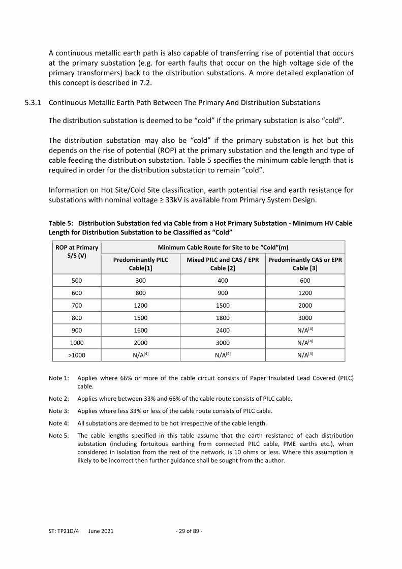
The distribution substation is deemed to be “cold” if the primary substation is also “cold”. The distribution substation may also be “cold” if the primary substation is hot but this depends on the rise of potential (ROP) at the primary substation and the length and type of cable feeding the distribution substation. Table 5 specifies the minimum cable length that is required in order for the distribution substation to remain “cold”. Information on Hot Site/Cold Site classification, earth potential rise and earth resistance for substations with nominal voltage ≥ 33kV is available from Primary System Design.
Table 5: Distribution Substation fed via Cable from a Hot Primary Substation - Minimum HV Cable Length for Distribution Substation to be Classified as “Cold”
ROP at Primary S/S (V)
Minimum Cable Route for Site to be “Cold”(m)
Predominantly PILC Cable[1]
Mixed PILC and CAS / EPR Cable [2]
Predominantly CAS or EPR Cable [3]
500 300 400 600
600 800 900 1200
700 1200 1500 2000
800 1500 1800 3000
900 1600 2400 N/A[4]
1000 2000 3000 N/A[4]
>1000 N/A[4] N/A[4] N/A[4]
Note 1: Applies where 66% or more of the cable circuit consists of Paper Insulated Lead Covered (PILC) cable.
Note 2: Applies where between 33% and 66% of the cable route consists of PILC cable.
Note 3: Applies where less 33% or less of the cable route consists of PILC cable.
Note 4: All substations are deemed to be hot irrespective of the cable length.
Note 5: The cable lengths specified in this table assume that the earth resistance of each distribution substation (including fortuitous earthing from connected PILC cable, PME earths etc.), when considered in isolation from the rest of the network, is 10 ohms or less. Where this assumption is likely to be incorrect then further guidance shall be sought from the author.
ST: TP21D/4 June 2021 - 30 of 89 -
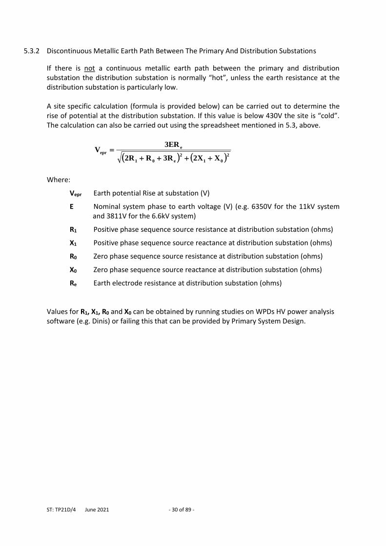
5.3.2 Discontinuous Metallic Earth Path Between The Primary And Distribution Substations
If there is not a continuous metallic earth path between the primary and distribution substation the distribution substation is normally “hot”, unless the earth resistance at the distribution substation is particularly low. A site specific calculation (formula is provided below) can be carried out to determine the rise of potential at the distribution substation. If this value is below 430V the site is “cold”. The calculation can also be carried out using the spreadsheet mentioned in 5.3, above.
2
01
2
e01
e
epr
XX2R3RR2
ER3V
Where:
Vepr Earth potential Rise at substation (V)
E Nominal system phase to earth voltage (V) (e.g. 6350V for the 11kV system and 3811V for the 6.6kV system)
R1 Positive phase sequence source resistance at distribution substation (ohms)
X1 Positive phase sequence source reactance at distribution substation (ohms)
R0 Zero phase sequence source resistance at distribution substation (ohms)
X0 Zero phase sequence source reactance at distribution substation (ohms)
Re Earth electrode resistance at distribution substation (ohms)
Values for R1, X1, R0 and X0 can be obtained by running studies on WPDs HV power analysis software (e.g. Dinis) or failing this that can be provided by Primary System Design.
ST: TP21D/4 June 2021 - 31 of 89 -
Figure 15: Process to Determine the Hot / Cold Status of a Distribution Substation
START
No
Yes
No
No
Yes
Yes
Distribution s/s is “hot”,
segregate HV & LV
earths
Distribution s/s is “cold”,
combine HV & LV
earths
No
Yes
Is there a
continuous metallic
path for earth fault
current to return to
the primary s/s (e.g.
cable sheath)?
Is the calculated rise of
potential at the distribution
s/s less than than 430V?
Is the primary s/s
“cold”?
Check Table 5.
Is the cable route length
> required value?
ST: TP21D/4 June 2021 - 32 of 89 -
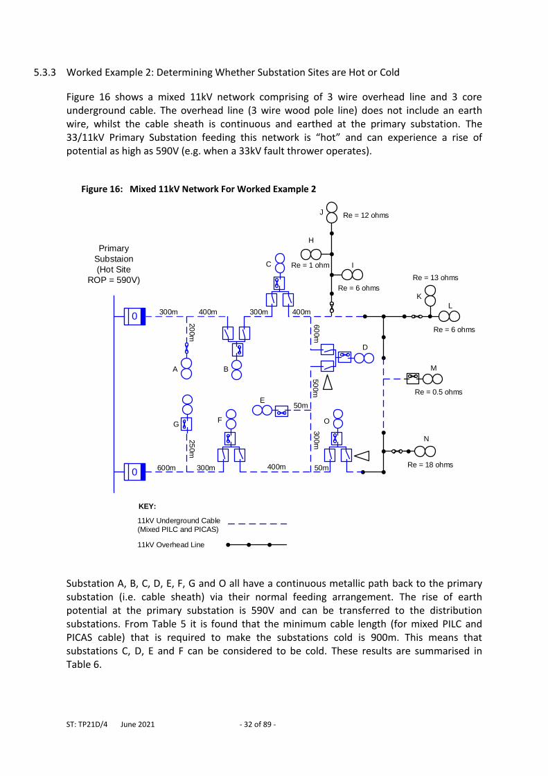
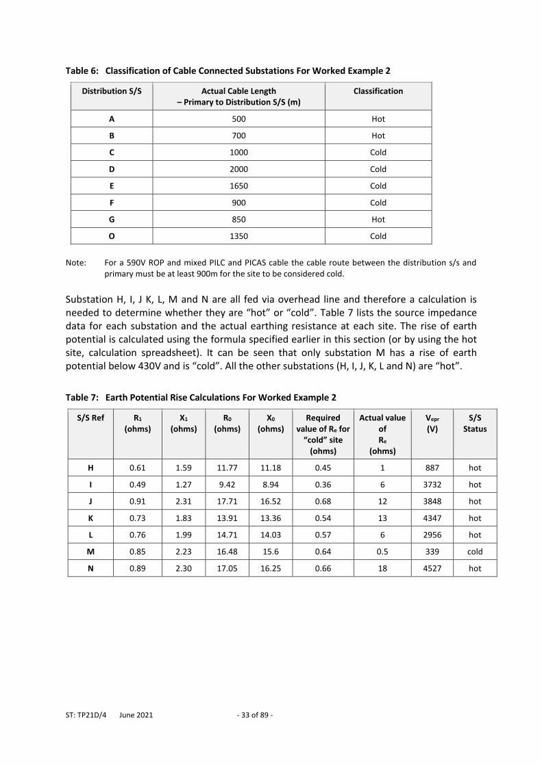
5.3.3 Worked Example 2: Determining Whether Substation Sites are Hot or Cold
Figure 16 shows a mixed 11kV network comprising of 3 wire overhead line and 3 core underground cable. The overhead line (3 wire wood pole line) does not include an earth wire, whilst the cable sheath is continuous and earthed at the primary substation. The 33/11kV Primary Substation feeding this network is “hot” and can experience a rise of potential as high as 590V (e.g. when a 33kV fault thrower operates).
Substation A, B, C, D, E, F, G and O all have a continuous metallic path back to the primary substation (i.e. cable sheath) via their normal feeding arrangement. The rise of earth potential at the primary substation is 590V and can be transferred to the distribution substations. From Table 5 it is found that the minimum cable length (for mixed PILC and PICAS cable) that is required to make the substations cold is 900m. This means that substations C, D, E and F can be considered to be cold. These results are summarised in Table 6.
Figure 16: Mixed 11kV Network For Worked Example 2
0
0
Primary
Substaion
(Hot Site
ROP = 590V)
A B
C
D
E
FG
H
I
J
K
L
M
N
O
11kV Underground Cable
(Mixed PILC and PICAS)
11kV Overhead Line
KEY:
Re = 0.5 ohms
Re = 18 ohms
Re = 6 ohms
Re = 13 ohms
Re = 6 ohms
Re = 1 ohm
Re = 12 ohms
300m
20
0m
400m 300m 400m
60
0m
50
0m
50m
30
0m
400m300m 600m
25
0m
50m
ST: TP21D/4 June 2021 - 33 of 89 -
Table 6: Classification of Cable Connected Substations For Worked Example 2
Distribution S/S Actual Cable Length – Primary to Distribution S/S (m)
Classification
A 500 Hot
B 700 Hot
C 1000 Cold
D 2000 Cold
E 1650 Cold
F 900 Cold
G 850 Hot
O 1350 Cold
Note: For a 590V ROP and mixed PILC and PICAS cable the cable route between the distribution s/s and
primary must be at least 900m for the site to be considered cold.
Substation H, I, J K, L, M and N are all fed via overhead line and therefore a calculation is needed to determine whether they are “hot” or “cold”. Table 7 lists the source impedance data for each substation and the actual earthing resistance at each site. The rise of earth potential is calculated using the formula specified earlier in this section (or by using the hot site, calculation spreadsheet). It can be seen that only substation M has a rise of earth potential below 430V and is “cold”. All the other substations (H, I, J, K, L and N) are “hot”.
Table 7: Earth Potential Rise Calculations For Worked Example 2
S/S Ref R1 (ohms)
X1
(ohms) R0
(ohms) X0
(ohms) Required
value of Re for “cold” site
(ohms)
Actual value of Re
(ohms)
Vepr
(V) S/S
Status
H 0.61 1.59 11.77 11.18 0.45 1 887 hot
I 0.49 1.27 9.42 8.94 0.36 6 3732 hot
J 0.91 2.31 17.71 16.52 0.68 12 3848 hot
K 0.73 1.83 13.91 13.36 0.54 13 4347 hot
L 0.76 1.99 14.71 14.03 0.57 6 2956 hot
M 0.85 2.23 16.48 15.6 0.64 0.5 339 cold
N 0.89 2.30 17.05 16.25 0.66 18 4527 hot
ST: TP21D/4 June 2021 - 34 of 89 -
5.4 Distribution Substations – General
Earthing requirements for distribution substations (with exception of those used to provide supplies to Major Substations and to equipment fixed to high voltage structures, e.g. HV poles and pylons) are specified below. These two exceptions are covered in ST: TP21B and ST: SD6E, respectively. All metalwork associated with distribution substations (e.g. transformer, switchgear and LV cabinet metalwork) must be connected to a locally installed HV earthing system. The transformer’s LV neutral shall be directly connected to an LV earthing system. LV and HV earth electrodes may be combined together if the site is deemed to be “cold” (see definition in Section 2). Where sites are “hot” HV and LV electrodes must be segregated by at least 9m. If a 9m segregation distance is not achievable (e.g. where the substation already exists) an individual assessment may be conducted, taking account of the actual rise in potential and earth electrode arrangement, to determine the required segregation distance.
5.5 Distribution Substations - Combined HV and LV Earthing Where there is a continuous metallic path (i.e. continuous cable) back to the primary substation the minimum acceptable horizontal length of buried earth electrode is 20m, although it is recommended that a longer horizontal length of electrode (up to approximately 50m) is installed where this can be carried out easily and cost effectively.
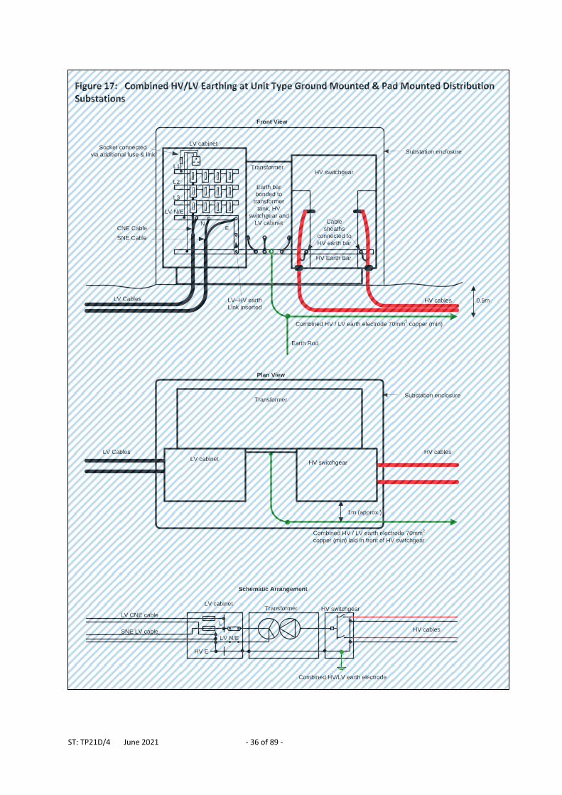
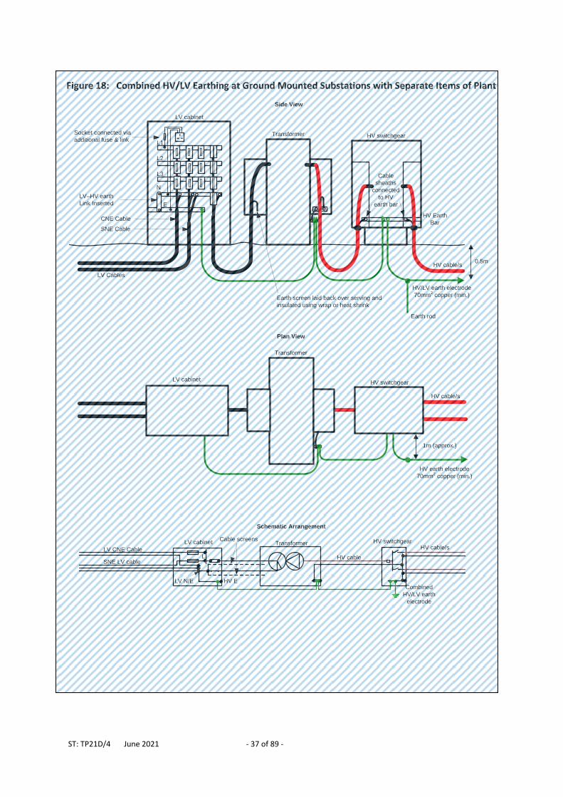
5.5.1 Ground Mounted and Pad Mounted Substations Requirements for combined HV and LV arrangements are shown in Figure 17 and Figure 18 and are listed below:
The earth electrode design is selected from the standard arrangements A, B, C or D (see Table 3).
LV cabinet link, between the HV earth bar and the LV neutral – earth bar, shall be connected.
Where necessary a separate substation earth bar may be installed to enable multiple earth connections to be made.
HV cable sheaths shall be bonded directly to the HV earthing system (it is not acceptable to rely on a fortuitous connection through HV metalwork).
Where an HV metering unit is installed this shall be bonded to the HV earthing system (it is not acceptable to rely on a fortuitous connection through HV metalwork).
The first section of HV electrode shall be buried immediately in front of the HV switchgear to help reduce touch potentials (potential difference between hands and feet) for switchgear operators.
ST: TP21D/4 June 2021 - 35 of 89 -
An LV socket may be provided within the LV cabinet.
LV substation auxiliary supplies (e.g. for lighting, sockets etc.) shall be derived from a suitably fused terminal blocks located within the LV cabinet. Such wiring shall satisfy the requirements of BS 7671 (IET Wiring Recommendations). It is recommended that auxiliary circuits that supply a.c. sockets within the substation are protected by a type A RCD (residual current device) unless they also supply essential safety related equipment (such as protection or fire alarm / fire-fighting equipment).
Pad-mounted transformers may be installed without additional fences or enclosures where security risks are low and they are deemed to be aesthetically acceptable.
Further information on substation fencing is provided in 5.7.
ST: TP21D/4 June 2021 - 36 of 89 -
Figure 17: Combined HV/LV Earthing at Unit Type Ground Mounted & Pad Mounted Distribution Substations
HV switchgear Transformer
LV cabinet
HV Earth Bar
Cable
sheaths
connected to
HV earth bar
Earth bar
bonded to
transformer
tank, HV
switchgear and
LV cabinet
LV–HV earth
Link inserted
Combined HV / LV earth electrode 70mm2 copper (min)
L1
L2
L3
LV N/E
HV cablesLV Cables
Front View
Socket connected
via additional fuse & link
L
LV CNE cable
HV E
LV cabinetTransformer HV switchgear
SNE LV cable HV cables
Combined HV/LV earth electrode
LV N/E
NECNE Cable
SNE Cable
Schematic Arrangement
Transformer
HV switchgear LV cabinet
Plan View
LV Cables HV cables
Combined HV / LV earth electrode 70mm2
copper (min) laid in front of HV switchgear
1m (approx.)
0.5m
Earth Rod
Substation enclosure
Substation enclosure
ST: TP21D/4 June 2021 - 37 of 89 -
Figure 18: Combined HV/LV Earthing at Ground Mounted Substations with Separate Items of Plant
LV cabinet Transformer HV switchgear
Schematic Arrangement
HV cable/s
HV switchgear Transformer
HV Earth
Bar
Cable
sheaths
connected
to HV
earth bar
HV earth electrode
70mm2 copper (min.)
HV cable/s
Side View
Combined
HV/LV earth
electrode
Earth screen laid back over serving and
insulated using wrap or heat shrink
Cable screens
HV cableLLV CNE Cable
SNE LV cable
HV ELV N/E
LV cabinet
L1
L2
L3
LV Cables
Socket connected via
additional fuse & link
N
E
CNE Cable
SNE Cable
LV–HV earth
Link Inserted
LV cabinet
Transformer
HV switchgear
Plan View
1m (approx.)
HV cable/s
0.5m
HV/LV earth electrode
70mm2 copper (min.)
Earth rod
ST: TP21D/4 June 2021 - 38 of 89 -
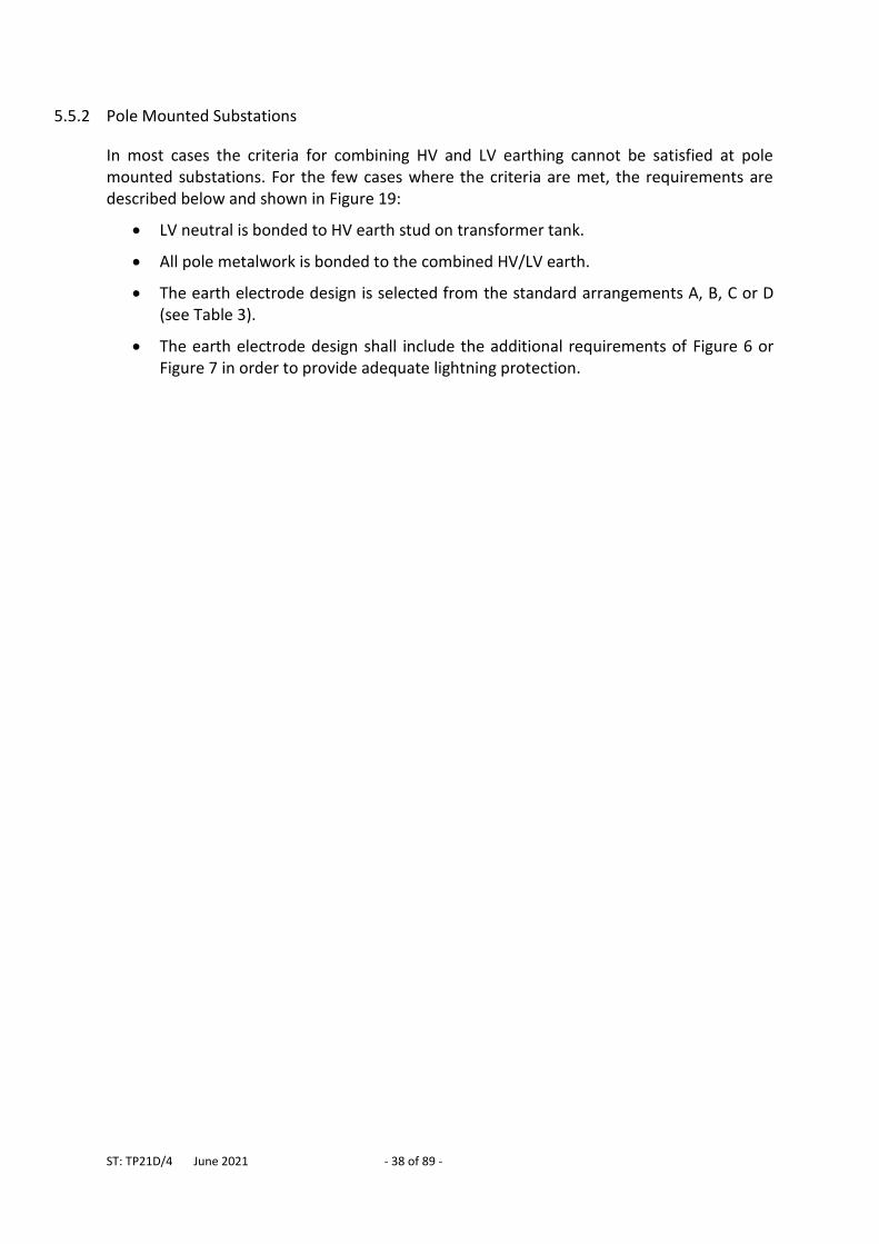
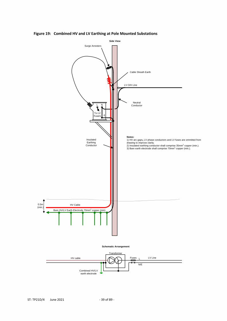
5.5.2 Pole Mounted Substations
In most cases the criteria for combining HV and LV earthing cannot be satisfied at pole mounted substations. For the few cases where the criteria are met, the requirements are described below and shown in Figure 19:
LV neutral is bonded to HV earth stud on transformer tank.
All pole metalwork is bonded to the combined HV/LV earth.
The earth electrode design is selected from the standard arrangements A, B, C or D (see Table 3).
The earth electrode design shall include the additional requirements of Figure 6 or Figure 7 in order to provide adequate lightning protection.
ST: TP21D/4 June 2021 - 39 of 89 -
Figure 19: Combined HV and LV Earthing at Pole Mounted Substations
L N
Bare HV/LV Earth Electrode 70mm2 copper (min)
To LV
Fuse/s
Insulated
Earthing
Conductor
LV O/H Line
HV Cable
Neutral
Conductor
Cable Sheath Earth
Notes:
1) HV arc gaps, LV phase conductors and LV fuses are ommitted from
drawing to improve clarity.
2) Insulated earthing conductor shall comprise 35mm2 copper (min.).
3) Bare earth electrode shall comprise 70mm2 copper (min.).
Surge Arresters
E
Transformer
Schematic Arrangement
Combined HV/LV
earth electrode
LV LineHV cable Fuses
Side View
L
N/E
0.5m
(min.)
ST: TP21D/4 June 2021 - 40 of 89 -
5.6 Distribution Substations - Segregated HV and LV Earthing
Where the criteria for combining HV and LV earthing systems cannot be met HV and LV electrodes shall be physically segregated. Buried HV electrode shall be segregated by at least 9m from buried LV electrode and from other buried metalwork or metallic services connected (directly or indirectly) to the LV earthing system. HV earthing electrode shall be installed close to the associated HV equipment to provide adequate lightning protection and to minimise touch potentials in and around the HV equipment. LV electrode shall be segregated away from the HV electrode by using insulated earthing conductor (e.g. PVC insulated). The insulated serving provided on modern cables such as consac, wavecon, tryden etc. ensure they are adequately segregated form HV electrode even when they are laid within 9m. The Hessian serving of older PILC (paper insulated, lead covered) LV cables does not have insulating properties and so where such cables are laid within 9m of an HV electrode they must be insulated by applying an appropriate wrap around the outside of the cable or by installing them within insulated and sealed ducting. PME earth electrodes and bare LV earthing conductor installed as part of a standard underground service joint, must not be placed within 9m of an HV earth electrode. The location of substations shall be chosen so that HV and LV electrodes can be adequately segregated. This will require substations to be placed well away from steel frame buildings, lightning protection electrodes, street lamps and other buried metallic services. Following the installation of segregated HV and LV earthing systems a test shall, as far as is reasonably practicable, be carried out to confirm the two systems do not overlap. The test method is specified in ST: TP21O. Typical arrangements for segregating HV and LV earthing are shown in Figure 20 to Figure 30 inclusive. The minimum LV and HV earthing electrode lengths that satisfy resistance and, where necessary, surface area requirements are chosen from Table 4. The minimum size of insulated earthing conductor (i.e. earthing conductor used above ground) is 35mm2 (copper). The minimum size of bare earthing electrode is 70mm2 (copper).
ST: TP21D/4 June 2021 - 41 of 89 -
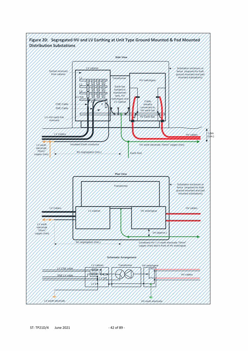
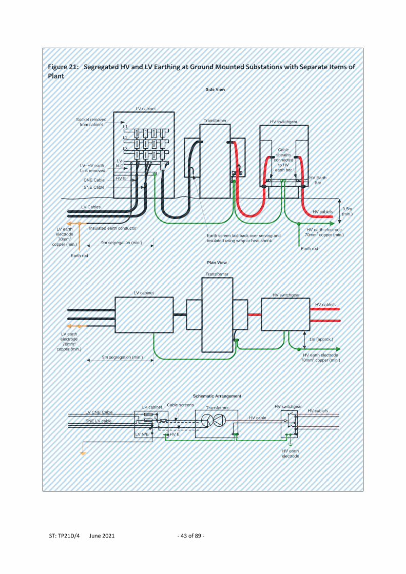
5.6.1 Ground Mounted and Pad Mounted Substations The requirements for segregating HV and LV earths are described below and shown in Figure 20 and Figure 21:
The HV earth electrode design is selected from the standard arrangements A, B, C or D (see Table 3).
The LV earth electrode design is selected from the standard arrangements A, B or C (see Table 3).
HV-LV earth link (connecting between the HV earth bar and the LV neutral – earth bar) shall be disconnected.
Any LV sockets within the cabinet shall be removed. HV Cable sheaths shall be bonded directly to the HV earthing system (it is not
acceptable to rely on a fortuitous connection through HV metalwork). Where an HV metering unit is installed this shall be bonded to the HV earthing
system (it is not acceptable to rely on a fortuitous connection through HV metalwork).
The first section of HV electrode shall be buried immediately in front of the HV cabinet / HV switchgear to help reduce touch potentials (potential difference between hands and feet) for operators.
Insulated LV earth conductor shall be connected to the LV neutral (inside LV fuse cabinet) and laid away from the substation, in a separate trench to the HV electrode (preferably in the opposite direction from the HV earth electrode). The LV earthing conductor shall be connected to bare earthing electrode once the 9m segregation distance is achieved.
Where necessary a separate substation earth bar may be installed to enable multiple earth connections to be made.
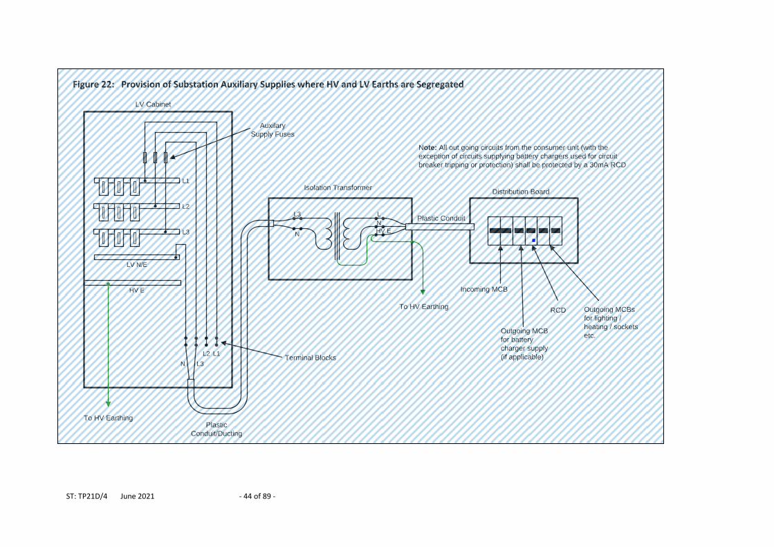
LV substation auxiliary supplies (e.g. for lighting, sockets etc.) are not normally provided where HV and LV earths are segregated. If auxiliary supplies are required the follow guidance shall be followed: (i) If only substation lighting is required all the associated equipment (light
fittings, switches etc.) shall comprise entirely of Class II equipment, as defined in to BS 7671 (i.e. double insulated equipment that does not have an earth connection). The circuit shall be derived from the LV busbars and shall be suitably fused. Live and neutral conductors (only) shall be run within plastic conduit to the switches and light fittings. An earth conductor (circuit protective conductor) shall not be installed.
(ii) If auxiliary supplies are required for sockets or other equipment that requires an earth (e.g. battery charger, actuators etc.) these supplies shall be derived from a 1:1 isolation transformer rated for 7kV a.c. for 1 minute between windings and between the incoming winding and the casing shall be installed. Further information is given in Figure 22.
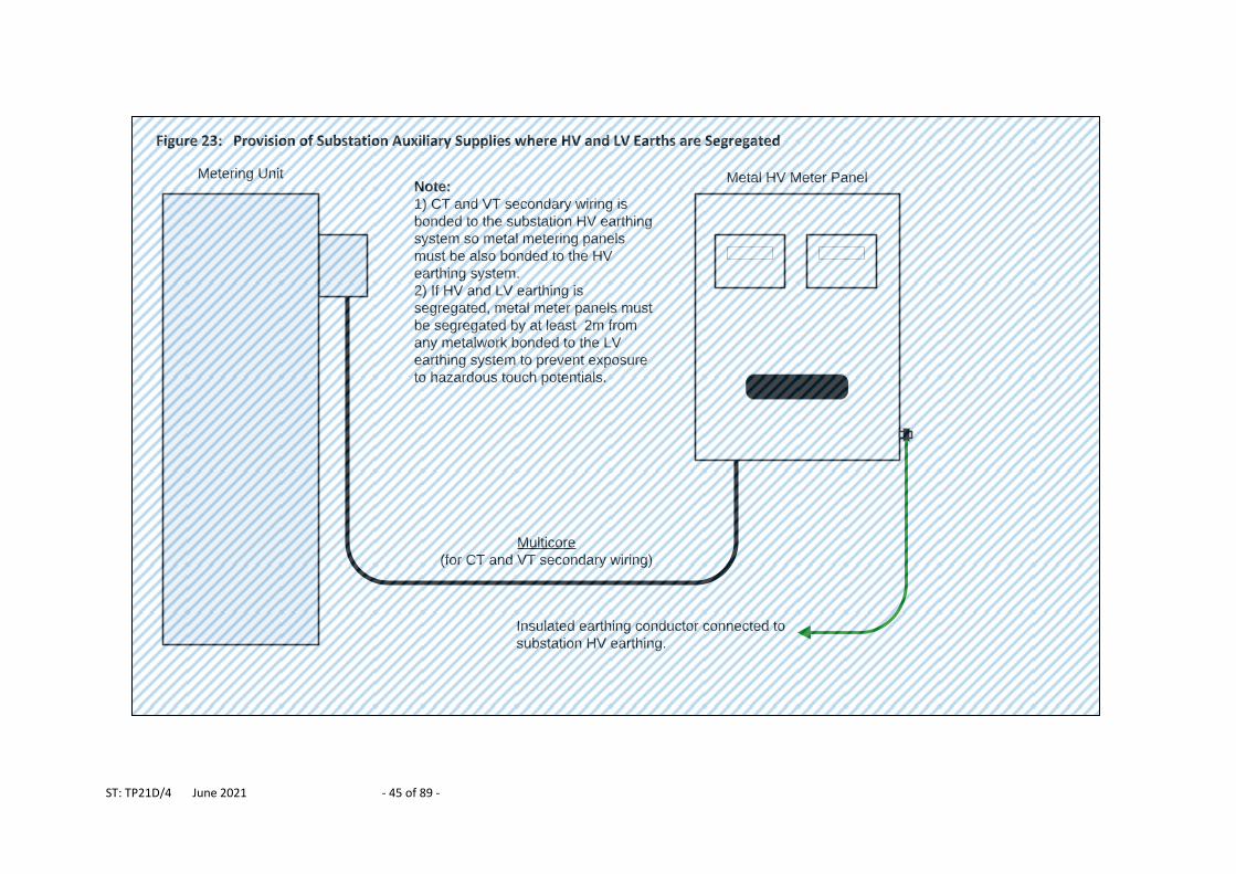
Metal HV metering panels shall be bonded to the substation HV earth. A minimum distance of at least 2m shall be maintained between any extraneous metalwork associated with the HV metering panel and extraneous metalwork connected to the LV earth, to prevent hazardous touch potentials (see Figure 23).
Pad-mounted transformers must be installed within GRP enclosures or fenced off (preferably with non-conducting fencing materials, such as wood) to minimise the touch potential risk.
Guidance on substation fencing is provided in 5.7.
ST: TP21D/4 June 2021 - 42 of 89 -
Figure 20: Segregated HV and LV Earthing at Unit Type Ground Mounted & Pad Mounted Distribution Substations
HV switchgear Transformer
LV cabinet
HV Earth Bar
Cable
sheaths
connected to
HV earth bar
Earth bar
bonded to
transformer
tank, HV
switchgear and
LV cabinet
LV–HV earth link
removed
HV earth electrode 70mm2 copper (min)
L1
L2
L3
LV N/E
HV cablesLV Cables
Side View
Socket removed
from cabinet
L
LV CNE cable
LV E
LV cabinet Transformer HV switchgear
SNE LV cable HV cables
HV earth electrode
LV N/E
NECNE Cable
SNE Cable
Schematic Arrangement
Transformer
HV switchgear
Plan View
LV Cables HV cables
Combined HV / LV earth electrode 70mm2
copper (min) laid in front of HV switchgear
1m (approx.)
0.5m
(min.)
Earth Rod
LV earth
electrode
70mm2
copper (min)9m segregation (min.)
Insulated Earth conductor
LV cabinet
LV earth
electrode
70mm2
copper (min)
9m segregation (min.)
LV earth electrode
Substation enclosure or
fence (required for both
ground mounted and pad
mounted substations)
Substation enclosure or
fence (required for both
ground mounted and pad
mounted substations)
ST: TP21D/4 June 2021 - 43 of 89 -
Figure 21: Segregated HV and LV Earthing at Ground Mounted Substations with Separate Items of Plant
LV cabinet Transformer HV switchgear
Schematic Arrangement
HV cable/s
HV switchgear Transformer
HV Earth
Bar
Cable
sheaths
connected
to HV
earth bar
HV earth electrode
70mm2 copper (min.)
HV cable/s
Side View
HV earth
electrode
Earth screen laid back over serving and
insulated using wrap or heat shrink
Cable screens
HV cableLLV CNE Cable
SNE LV cable
HV ELV N/E
LV cabinet
L1
L2
L3
LV Cables
Socket removed
from cabinet
LV
N-E
HV ECNE Cable
SNE Cable
LV–HV earth
Link removed
LV cabinet
Transformer
HV switchgear
Plan View
1m (approx.)
HV cable/s
9m segregation (min.)
HV earth electrode
70mm2 copper (min.)
Earth rod
LV earth
electrode
70mm2
copper (min.)
LV earth
electrode
70mm2
copper (min.)
9m segregation (min.)
Earth rod
Insulated earth conductor
0.5m
(min.)
ST: TP21D/4 June 2021 - 44 of 89 -
Figure 22: Provision of Substation Auxiliary Supplies where HV and LV Earths are Segregated
LV Cabinet
Isolation TransformerDistribution Board
L1
LV N/E
L3
N
L
N
HV E
Incoming MCB
To HV Earthing
RCD
Note: All out going circuits from the consumer unit (with the
exception of circuits supplying battery chargers used for circuit
breaker tripping or protection) shall be protected by a 30mA RCD
Plastic
Conduit/Ducting
Plastic Conduit
Outgoing MCB
for battery
charger supply
(if applicable)
Outgoing MCBs
for lighting /
heating / sockets
etc.
L2
L3
HV E
N
L1L2
L3
To HV Earthing
Terminal Blocks
Auxilary
Supply Fuses
ST: TP21D/4 June 2021 - 45 of 89 -
Figure 23: Provision of Substation Auxiliary Supplies where HV and LV Earths are Segregated
Metal HV Meter PanelMetering Unit
Multicore
(for CT and VT secondary wiring)
Insulated earthing conductor connected to
substation HV earthing.
Note:
1) CT and VT secondary wiring is
bonded to the substation HV earthing
system so metal metering panels
must be also bonded to the HV
earthing system.
2) If HV and LV earthing is
segregated, metal meter panels must
be segregated by at least 2m from
any metalwork bonded to the LV
earthing system to prevent exposure
to hazardous touch potentials.
ST: TP21D/4 June 2021 - 46 of 89 -
5.6.2 Pole Mounted Substations
Figure 24 to Figure 30 inclusive show a number of methods for segregating HV and LV earthing at pole mounted substations. In each case the following requirements also apply:
HV earth electrode design is selected from the standard arrangements A, B, C or D (see Table 3) and the additional requirements of Figure 6 or Figure 7 incorporated in order to provide adequate lightning protection.
The LV earth electrode design is selected from the standard arrangements A, B or C (see Table 3).
A neutral-earth surge arrester is installed between the substation LV neutral and metalwork earth.
HV earth conductor shall be placed as far as possible from LV earth, neutral and phase conductors (i.e. on opposite sides of the pole) to prevent, as far as possible lightning causing a flashover between the two earthing systems.
Where hessian served LV cables (e.g. PILC cables) are installed within 9m of HV earthing electrode they shall be insulated by applying a suitable wrap or by installing them within insulating (e.g. polyethylene) ducts which are then sealed to prevent moisture ingress. Any hessian served HV cables laid within 9m of the bare LV electrode must be insulated using the same technique.
The LV earth electrode shall be connected to LV neutral using one of the following options:
Option 1 LV neutral is earthed at the transformer pole (see Figure 24, Figure 25, Figure 26 and Figure 27)
Option 2 LV neutral is earthed one span away from the transformer pole (see Figure 28). This method is only acceptable where only one LV circuit is connected to the transformer and this circuit runs away from the transformer pole in just one direction. In addition, all customer connections must be provided at or beyond the pole connected to the main LV earth electrode. These restrictions minimise the risk of customer connections becoming disconnected from earth if the overhead line is damaged or if work being carried out on the overhead line.
Option 3 LV neutral is earthed at the customer connection point (see Figure 29 and Figure 30). These options utilise PNB (protective neutral bonding) earthing and may only be used where the substation provides just one connection point. PNB must not be offered where more than one connection point is to be provided from the substation.
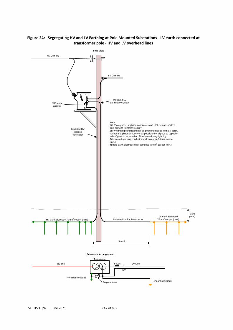
ST: TP21D/4 June 2021 - 47 of 89 -
Figure 24: Segregating HV and LV Earthing at Pole Mounted Substations - LV earth connected at transformer pole - HV and LV overhead lines
E
Insulated LV Earth conductor
Insulated HV
earthing
conductor
LV O/H line
HV O/H line
Insulated LV
earthing conductor
L N
N-E surge
arrester
Note:
1) HV arc gaps, LV phase conductors and LV fuses are omitted
from drawing to improve clarity.
2) HV earthing conductor shall be positioned as far from LV earth,
neutral and phase conductors as possible (i.e. clipped to opposite
side of pole) to reduce risk of flashover during lightning.
3) Insulated earthing conductor shall comprise 35mm2 copper
(min.).
4) Bare earth electrode shall comprise 70mm2 copper (min.).
9m min.
Side View
Transformer
Schematic Arrangement
HV earth electrode
LV LineHV line Fuses L
N/E
LV earth electrodeSurge arrester
0.5m
(min.)
HV earth electrode 70mm2 copper (min.)
LV earth electrode
70mm2 copper (min.)
ST: TP21D/4 June 2021 - 48 of 89 -
Figure 26 Segregated HV and LV Earthing at Pole Mounted Substations - LV Earth Connected at Transformer Pole - HV Cable, LV Overhead Line
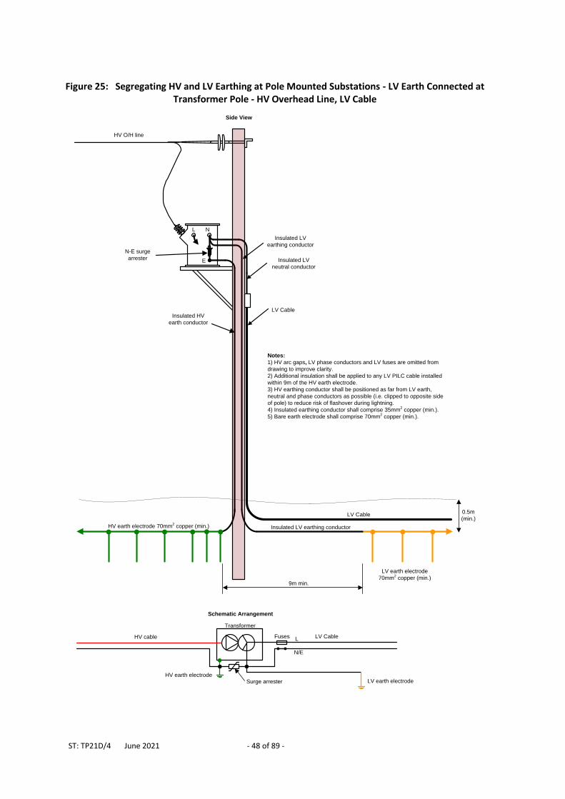
Figure 25: Segregating HV and LV Earthing at Pole Mounted Substations - LV Earth Connected at Transformer Pole - HV Overhead Line, LV Cable
N
Insulated LV earthing conductor
Insulated HV
earth conductor
HV O/H line
Insulated LV
earthing conductor
E
L
LV Cable
Insulated LV
neutral conductor
LV Cable
Notes:
1) HV arc gaps, LV phase conductors and LV fuses are omitted from
drawing to improve clarity.
2) Additional insulation shall be applied to any LV PILC cable installed
within 9m of the HV earth electrode.
3) HV earthing conductor shall be positioned as far from LV earth,
neutral and phase conductors as possible (i.e. clipped to opposite side
of pole) to reduce risk of flashover during lightning.
4) Insulated earthing conductor shall comprise 35mm2 copper (min.).
5) Bare earth electrode shall comprise 70mm2 copper (min.).
9m min.
N-E surge
arrester
0.5m
(min.)
Side View
Transformer
Schematic Arrangement
HV earth electrode
LV CableHV cable Fuses L
N/E
LV earth electrodeSurge arrester
LV earth electrode
70mm2 copper (min.)
HV earth electrode 70mm2 copper (min.)
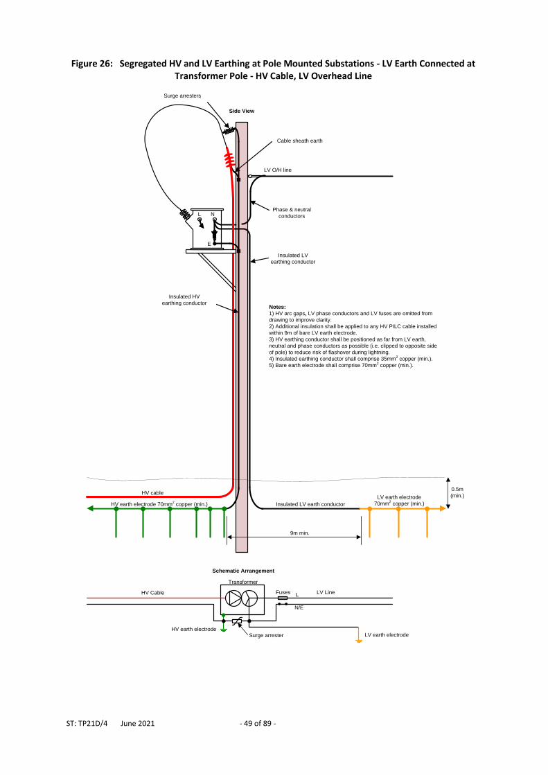
ST: TP21D/4 June 2021 - 49 of 89 -
Figure 26: Segregated HV and LV Earthing at Pole Mounted Substations - LV Earth Connected at Transformer Pole - HV Cable, LV Overhead Line
HV earth electrode 70mm2 copper (min.) Insulated LV earth conductor
Insulated HV
earthing conductor
LV O/H line
Insulated LV
earthing conductor
HV cable
Phase & neutral
conductors
Cable sheath earth
Surge arresters
N
E
L
Notes:
1) HV arc gaps, LV phase conductors and LV fuses are omitted from
drawing to improve clarity.
2) Additional insulation shall be applied to any HV PILC cable installed
within 9m of bare LV earth electrode.
3) HV earthing conductor shall be positioned as far from LV earth,
neutral and phase conductors as possible (i.e. clipped to opposite side
of pole) to reduce risk of flashover during lightning.
4) Insulated earthing conductor shall comprise 35mm2 copper (min.).
5) Bare earth electrode shall comprise 70mm2 copper (min.).
9m min.
LV earth electrode
70mm2 copper (min.)
Transformer
Schematic Arrangement
HV earth electrode
LV LineHV Cable Fuses L
N/E
LV earth electrodeSurge arrester
0.5m
(min.)
Side View
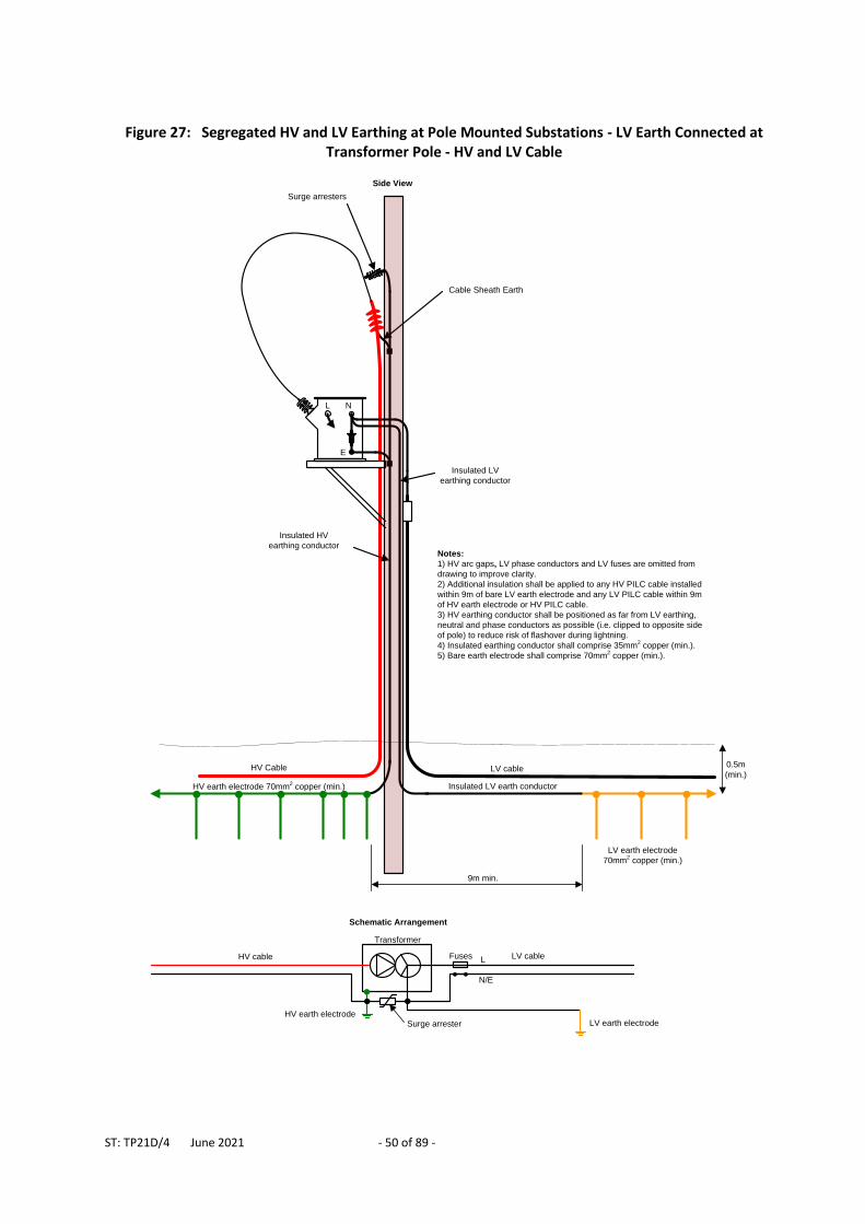
ST: TP21D/4 June 2021 - 50 of 89 -
Figure 27: Segregated HV and LV Earthing at Pole Mounted Substations - LV Earth Connected at Transformer Pole - HV and LV Cable
Insulated LV earth conductor
Insulated HV
earthing conductor
Insulated LV
earthing conductor
HV Cable
Cable Sheath Earth
Surge arresters
N
E
L
Notes:
1) HV arc gaps, LV phase conductors and LV fuses are omitted from
drawing to improve clarity.
2) Additional insulation shall be applied to any HV PILC cable installed
within 9m of bare LV earth electrode and any LV PILC cable within 9m
of HV earth electrode or HV PILC cable.
3) HV earthing conductor shall be positioned as far from LV earthing,
neutral and phase conductors as possible (i.e. clipped to opposite side
of pole) to reduce risk of flashover during lightning.
4) Insulated earthing conductor shall comprise 35mm2 copper (min.).
5) Bare earth electrode shall comprise 70mm2 copper (min.).
9m min.
LV cable0.5m
(min.)
HV earth electrode 70mm2 copper (min.)
LV earth electrode
70mm2 copper (min.)
Side View
Transformer
Schematic Arrangement
HV earth electrode
LV cableHV cable Fuses L
N/E
LV earth electrodeSurge arrester
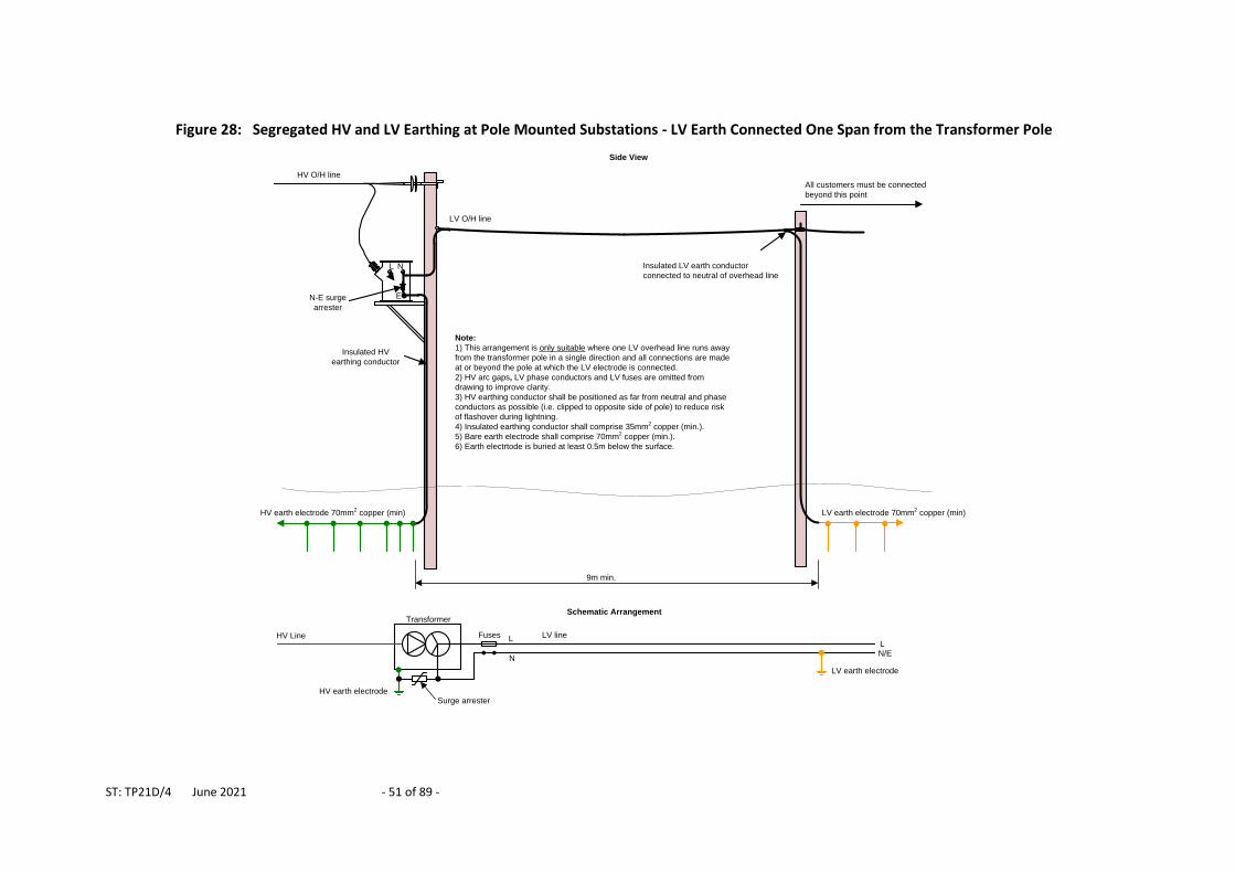
ST: TP21D/4 June 2021 - 51 of 89 -
Figure 28: Segregated HV and LV Earthing at Pole Mounted Substations - LV Earth Connected One Span from the Transformer Pole
E
Insulated HV
earthing conductor
LV O/H line
HV O/H line
Insulated LV earth conductor
connected to neutral of overhead lineL N
N-E surge
arrester
Note:
1) This arrangement is only suitable where one LV overhead line runs away
from the transformer pole in a single direction and all connections are made
at or beyond the pole at which the LV electrode is connected.
2) HV arc gaps, LV phase conductors and LV fuses are omitted from
drawing to improve clarity.
3) HV earthing conductor shall be positioned as far from neutral and phase
conductors as possible (i.e. clipped to opposite side of pole) to reduce risk
of flashover during lightning.
4) Insulated earthing conductor shall comprise 35mm2 copper (min.).
5) Bare earth electrode shall comprise 70mm2 copper (min.).
6) Earth electrtode is buried at least 0.5m below the surface.
9m min.
All customers must be connected
beyond this point
TransformerSchematic Arrangement
HV earth electrode
LV lineHV Line Fuses L
N
LV earth electrode
Surge arrester
LN/E
Side View
HV earth electrode 70mm2 copper (min) LV earth electrode 70mm
2 copper (min)
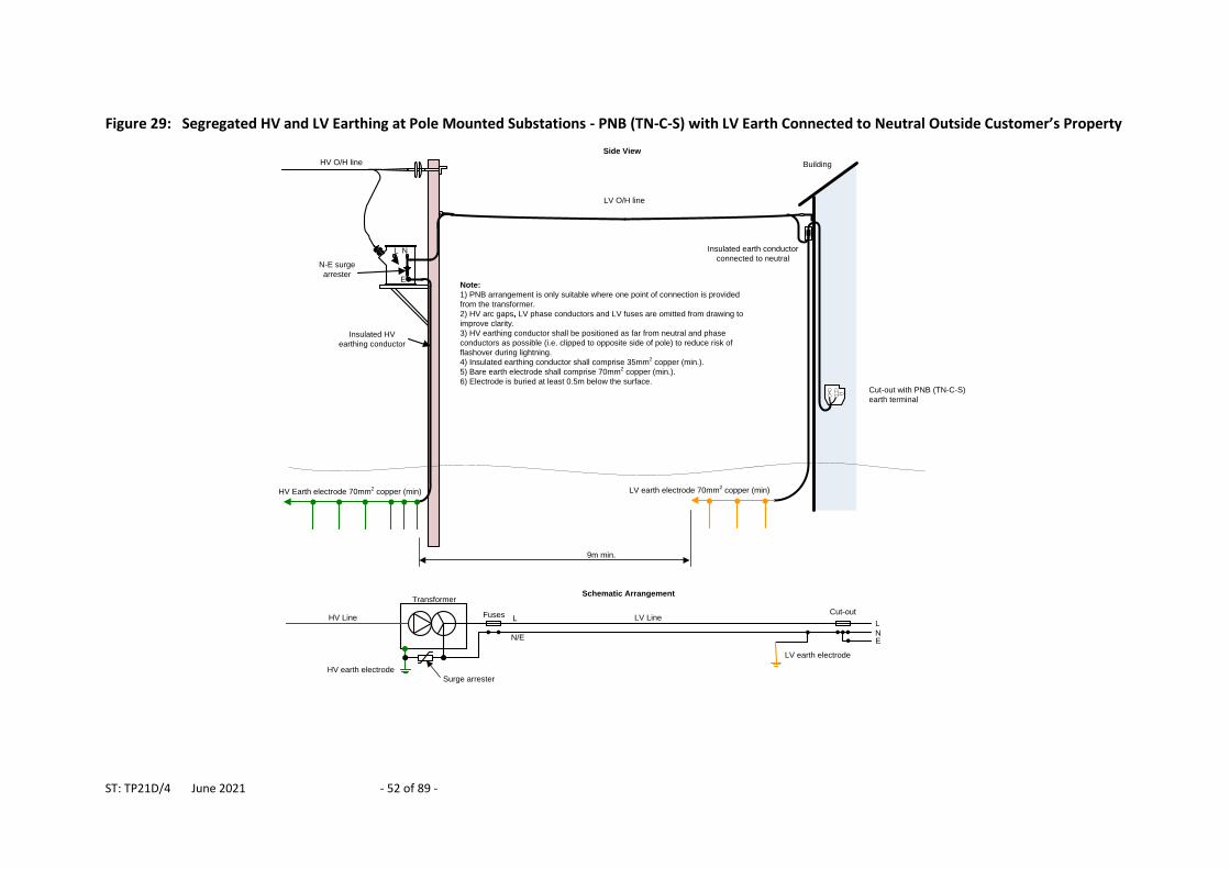
ST: TP21D/4 June 2021 - 52 of 89 -
Figure 29: Segregated HV and LV Earthing at Pole Mounted Substations - PNB (TN-C-S) with LV Earth Connected to Neutral Outside Customer’s Property
E
Insulated HV
earthing conductor
LV O/H line
HV O/H line
L N
N-E surge
arrester
Note:
1) PNB arrangement is only suitable where one point of connection is provided
from the transformer.
2) HV arc gaps, LV phase conductors and LV fuses are omitted from drawing to
improve clarity.
3) HV earthing conductor shall be positioned as far from neutral and phase
conductors as possible (i.e. clipped to opposite side of pole) to reduce risk of
flashover during lightning.
4) Insulated earthing conductor shall comprise 35mm2 copper (min.).
5) Bare earth electrode shall comprise 70mm2 copper (min.).
6) Electrode is buried at least 0.5m below the surface.
9m min.
Cut-out with PNB (TN-C-S)
earth terminal
Building
Insulated earth conductor
connected to neutral
Side View
LN
TransformerSchematic Arrangement
HV earth electrode
LV LineHV Line Fuses L
N/E
LV earth electrode
Surge arrester
E
Cut-out
HV Earth electrode 70mm2 copper (min) LV earth electrode 70mm
2 copper (min)
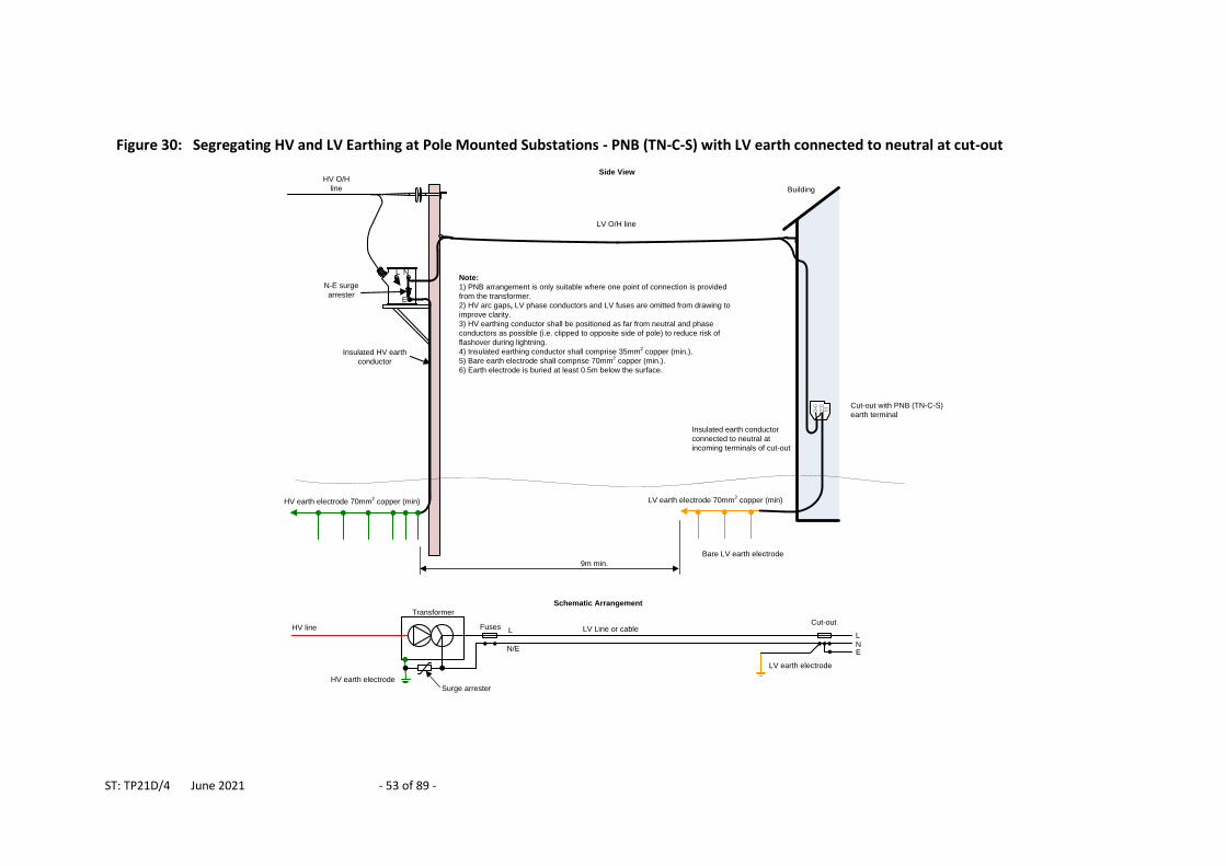
ST: TP21D/4 June 2021 - 53 of 89 -
Figure 30: Segregating HV and LV Earthing at Pole Mounted Substations - PNB (TN-C-S) with LV earth connected to neutral at cut-out
E
Insulated HV earth
conductor
LV O/H line
HV O/H
line
L N
N-E surge
arrester
Note:
1) PNB arrangement is only suitable where one point of connection is provided
from the transformer.
2) HV arc gaps, LV phase conductors and LV fuses are omitted from drawing to
improve clarity.
3) HV earthing conductor shall be positioned as far from neutral and phase
conductors as possible (i.e. clipped to opposite side of pole) to reduce risk of
flashover during lightning.
4) Insulated earthing conductor shall comprise 35mm2 copper (min.).
5) Bare earth electrode shall comprise 70mm2 copper (min.).
6) Earth electrode is buried at least 0.5m below the surface.
9m min.
Bare LV earth electrode
LN
Cut-out with PNB (TN-C-S)
earth terminal
Building
Insulated earth conductor
connected to neutral at
incoming terminals of cut-out
HV earth electrode 70mm2 copper (min) LV earth electrode 70mm
2 copper (min)
Transformer
Schematic Arrangement
HV earth electrode
LV Line or cableHV line Fuses L
N/E
LV earth electrode
Surge arrester
E
Cut-out
Side View
ST: TP21D/4 June 2021 - 54 of 89 -
5.7 Distribution Substations - Enclosures, Doors and Fencing Distribution substation enclosures, doors and fences should be constructed from non-conducting materials whenever possible, to eliminate any risk from hazardous potentials. In some cases it is necessary to install metal doors, enclosures or fencing for security reasons. Earthing requirements for enclosures, metal fences and metal doors are described below:
a) Fibreglass Enclosures
Fibreglass substations enclosures are commonly installed around distribution substations to provide a reasonable level of security and environmental protection. Fibreglass is a good insulator and eliminates touch potential hazards between the enclosure itself and the substation plant. The metal strip that is fitted below the door (known as a threshold strip) shall be bonded to the HV earth of the substation using copper conductor with a minimum cross-sectional area of 50mm2.
b) Steel anti-vandal enclosures with resin and grit coating
Metal anti-vandal substation enclosures are available that are coated with a layer of fibre glass resin impregnated with fine gravel or grit. The enclosure itself must be bonded to the substation HV earthing system using copper conductor with a minimum cross-section of 50mm2, to prevent hazardous touch potentials (between the substation plant and the metallic enclosure) using copper conductor. The external coating is highly insulating and therefore hazardous touch potentials outside the substation are eliminated (assuming the outer coating is intact). If the outer coating is damaged and significant areas of steel are exposed the enclosure should be replaced.
c) Steel enclosures with painted finish
In the past painted steel enclosures were often installed around distribution substations. These steel enclosures must be bonded to the substation HV earthing system with a copper conductor with a minimum cross-sectional area of 50mm2 to prevent hazardous touch potentials between the enclosure and the substation plant.
i) Combined Substation Earthing
Where the substation’s HV and LV earths are combined (i.e. the site is defined as cold) no further precautions are required for steel enclosures
ii) Segregated Substation Earthing
If the HV and LV earthing systems are segregated (i.e. the site is “hot”) the steel enclosure should be surrounded by non-metallic fencing that prevents members of the public touching the enclosure.
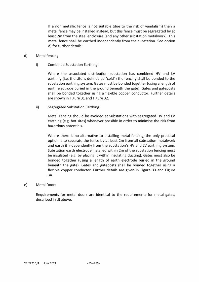
ST: TP21D/4 June 2021 - 55 of 89 -
If a non metallic fence is not suitable (due to the risk of vandalism) then a metal fence may be installed instead, but this fence must be segregated by at least 2m from the steel enclosure (and any other substation metalwork). This metal fence shall be earthed independently from the substation. See option d) for further details.
d) Metal fencing
i) Combined Substation Earthing
Where the associated distribution substation has combined HV and LV earthing (i.e. the site is defined as “cold”) the fencing shall be bonded to the substation earthing system. Gates must be bonded together (using a length of earth electrode buried in the ground beneath the gate). Gates and gateposts shall be bonded together using a flexible copper conductor. Further details are shown in Figure 31 and Figure 32.
ii) Segregated Substation Earthing
Metal Fencing should be avoided at Substations with segregated HV and LV earthing (e.g. hot sites) whenever possible in order to minimise the risk from hazardous potentials. Where there is no alternative to installing metal fencing, the only practical option is to separate the fence by at least 2m from all substation metalwork and earth it independently from the substation’s HV and LV earthing system. Substation earth electrode installed within 2m of the substation fencing must be insulated (e.g. by placing it within insulating ducting). Gates must also be bonded together (using a length of earth electrode buried in the ground beneath the gate). Gates and gateposts shall be bonded together using a flexible copper conductor. Further details are given in Figure 33 and Figure 34.
e) Metal Doors
Requirements for metal doors are identical to the requirements for metal gates, described in d) above.
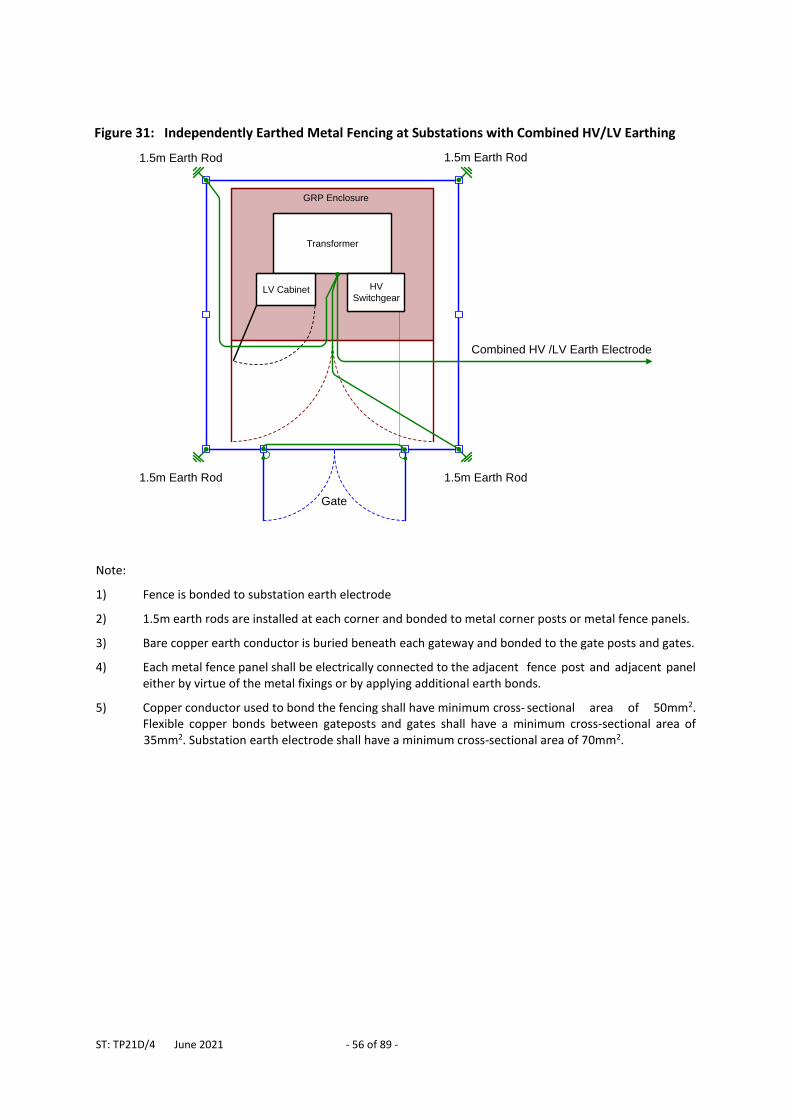
ST: TP21D/4 June 2021 - 56 of 89 -
Note:
1) Fence is bonded to substation earth electrode
2) 1.5m earth rods are installed at each corner and bonded to metal corner posts or metal fence panels.
3) Bare copper earth conductor is buried beneath each gateway and bonded to the gate posts and gates.
4) Each metal fence panel shall be electrically connected to the adjacent fence post and adjacent panel either by virtue of the metal fixings or by applying additional earth bonds.
5) Copper conductor used to bond the fencing shall have minimum cross- sectional area of 50mm2. Flexible copper bonds between gateposts and gates shall have a minimum cross-sectional area of 35mm2. Substation earth electrode shall have a minimum cross-sectional area of 70mm2.
Figure 31: Independently Earthed Metal Fencing at Substations with Combined HV/LV Earthing
Transformer
LV Cabinet
GRP Enclosure
HV
Switchgear
1.5m Earth Rod 1.5m Earth Rod
Gate
1.5m Earth Rod1.5m Earth Rod
Combined HV /LV Earth Electrode
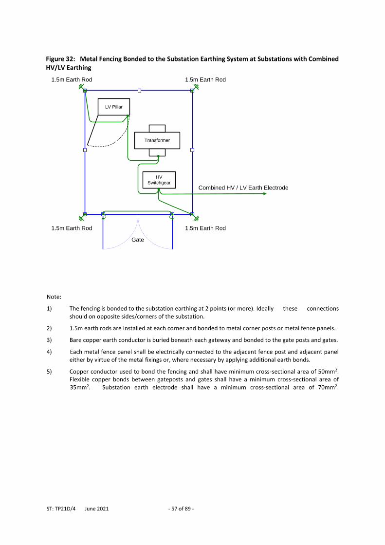
ST: TP21D/4 June 2021 - 57 of 89 -
Note:
1) The fencing is bonded to the substation earthing at 2 points (or more). Ideally these connections should on opposite sides/corners of the substation.
2) 1.5m earth rods are installed at each corner and bonded to metal corner posts or metal fence panels.
3) Bare copper earth conductor is buried beneath each gateway and bonded to the gate posts and gates.
4) Each metal fence panel shall be electrically connected to the adjacent fence post and adjacent panel either by virtue of the metal fixings or, where necessary by applying additional earth bonds.
5) Copper conductor used to bond the fencing and shall have minimum cross-sectional area of 50mm2. Flexible copper bonds between gateposts and gates shall have a minimum cross-sectional area of 35mm2. Substation earth electrode shall have a minimum cross-sectional area of 70mm2.
Figure 32: Metal Fencing Bonded to the Substation Earthing System at Substations with Combined HV/LV Earthing
Transformer
LV Pillar
HV
Switchgear
Gate
1.5m Earth Rod
1.5m Earth Rod1.5m Earth Rod
1.5m Earth Rod
Combined HV / LV Earth Electrode
ST: TP21D/4 June 2021 - 58 of 89 -
Note:
1) Fencing must be segregated from substation metalwork by at least 2m.
2) HV and LV earth electrodes are segregated by 9m.
3) Bare HV electrode is laid 1m in front of HV switchgear.
4) HV electrode is insulated where it passes within 2m of the metallic fence (e.g. by laying it inside plastic ducting).
5) 1.5m earth rods are installed at, and bonded to, each corner post or fence panel.
6) Each metal fence panel shall be electrically connected to the adjacent fence post and adjacent panel either by virtue of the metal fixings or, where necessary by applying additional earth bonds.
7) Bare copper earth conductor is buried beneath each gateway and bonded to the gate posts and gates.
8) Copper conductor used to bond the fencing shall have minimum cross-sectional area of 50mm2. Flexible copper bonds between gateposts and gates shall have a minimum cross-sectional area of 35mm2. Substation earth electrode shall have a minimum cross-sectional area of 70mm2.
Figure 33: Independently Earthed Metal Fencing System at Substations with Segregated HV and LV Earthing (Outdoor Arrangement)
Gate
1.5m Earth Rod
1.5m Earth Rod1.5m Earth Rod
1.5m Earth Rod
Substation HV
Earth Electrode
≥ 2m ≥ 2m
Substation LV Earth
Conductor (insulated to
provide 9m segregation
from HV electrode)
≥ 2
m
HV
Switchgear
Transformer
LV Pillar
≥ 2
m
≥ 2
m
≥ 2m
Pillar Door
Insulating Ducting
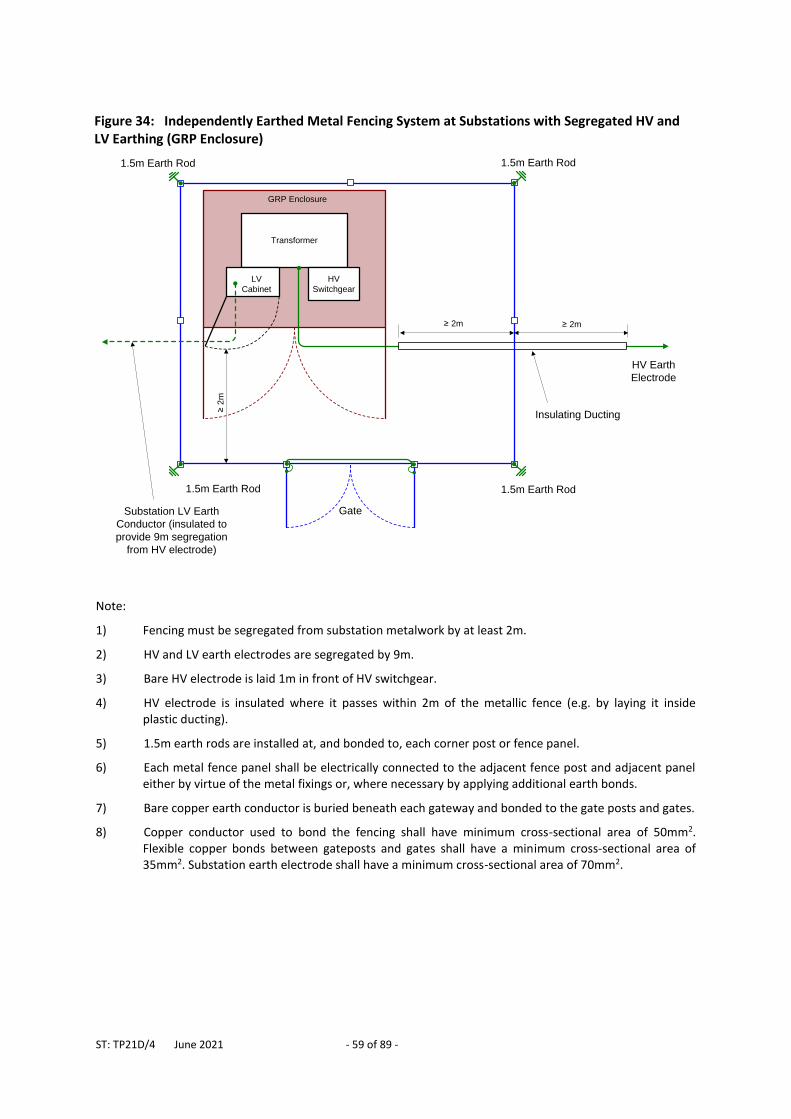
ST: TP21D/4 June 2021 - 59 of 89 -
Note:
1) Fencing must be segregated from substation metalwork by at least 2m.
2) HV and LV earth electrodes are segregated by 9m.
3) Bare HV electrode is laid 1m in front of HV switchgear.
4) HV electrode is insulated where it passes within 2m of the metallic fence (e.g. by laying it inside plastic ducting).
5) 1.5m earth rods are installed at, and bonded to, each corner post or fence panel.
6) Each metal fence panel shall be electrically connected to the adjacent fence post and adjacent panel either by virtue of the metal fixings or, where necessary by applying additional earth bonds.
7) Bare copper earth conductor is buried beneath each gateway and bonded to the gate posts and gates.
8) Copper conductor used to bond the fencing shall have minimum cross-sectional area of 50mm2. Flexible copper bonds between gateposts and gates shall have a minimum cross-sectional area of 35mm2. Substation earth electrode shall have a minimum cross-sectional area of 70mm2.
Figure 34: Independently Earthed Metal Fencing System at Substations with Segregated HV and LV Earthing (GRP Enclosure)
Transformer
GRP Enclosure
HV
Switchgear
1.5m Earth Rod 1.5m Earth Rod
Gate
1.5m Earth Rod1.5m Earth Rod
HV Earth
Electrode
≥ 2
m
≥ 2m ≥ 2m
LV
Cabinet
Substation LV Earth
Conductor (insulated to
provide 9m segregation
from HV electrode)
Insulating Ducting
ST: TP21D/4 June 2021 - 60 of 89 -
5.8 Distribution Substations - Pole Mounted Equipment (Excluding Transformers)
Most 11kV and 6.6kV overhead lines owned by WPD utilise unearthed construction (i.e. an earth wire is not provided and at the majority of poles the steelwork is left un-earthed). Where equipment is installed on the poles, e.g. switchgear the associated metalwork, including pole steelwork and brackets often has to be earthed. A list of pole-mounted equipment that requires earthing is given in 5.2. Pole metalwork is also earthed on poles that are jointly used by WPD and British Telecom. Earth electrode designs shall be in accordance with Section 4 of this document. The HV earth electrode design shall be selected from the standard arrangements A, B, C or D (see Table 3). Earthing conductor clipped to the pole shall be suitably insulated to prevent hazardous touch potentials. Where surge arresters or triggered arc gaps are installed the earth electrode shall include the additional requirements of Figure 6 or Figure 7 in order to provide adequate lightning protection. The earthing conductor shall be kept as short and straight as possible in order to minimise the earthing system impedance for lightning impulses. Specific requirements for earthing air break switch disconnectors (ABSDs) with handles operated from ground level and for pole-mounted equipment with control cubicles accessible without a ladder, are specified below:
5.8.1 ABSDs with Handle Operated from Ground Level New and substantially modified ABSDs shall be installed with a surface laid operator earth mat which is connected to the operating handle (see Figure 35). Equipment installed prior to the issue of this document have been provided with a buried operator earth mat instead (see Figure 36). The earth mat shall be placed directly in front of the operating handle and bonded to the handle so that the operator stands on the earth mat (if surface laid) or directly above the mat (if buried) when operating the ABSD. The operating rod shall include a suitable insulating insert to prevent hazardous potentials being transferred to the handle. Pole top metalwork shall be connected to a buried earth electrode which is segregated by at least 9m from the operator earth mat. The HV metalwork earth conductor shall be clipped to the opposite side of the pole to the operating handle earth conductor to minimise the chance of a flashover between the two earthing systems.
ST: TP21D/4 June 2021 - 61 of 89 -
5.8.2 Switchgear and Regulators with Ground Level Control Boxes
Requirements for pole-mounted switchgear and regulators with control cubicles accessible without a ladder are shown in Figure 37 and are similar to requirements for ABSDs described above. The main difference is that the control cubicle is bonded to the switchgear by virtue of their umbilical cable and therefore it is not possible to segregate the control cubicle (and operating mat) earthing from the switchgear earthing. Pole top metalwork and control cubicle metalwork is connected to the earth mat and to a buried earth electrode. The earth mat shall be placed directly in front of the operating handle in a position that ensures the operator will stand on the earth mat when operating the equipment. This arrangement keeps touch potentials to a minimum should an earth fault occur on the pole. Retrospective action is required to install a surface laid earth mat at any existing site that does not already have one. MOD 378 has been set up in CROWN to schedule / monitor this work. Where an existing earth mat is in place, but it is smaller than the minimum size specified in Figure 37, it is not necessary to replace it with a larger one.
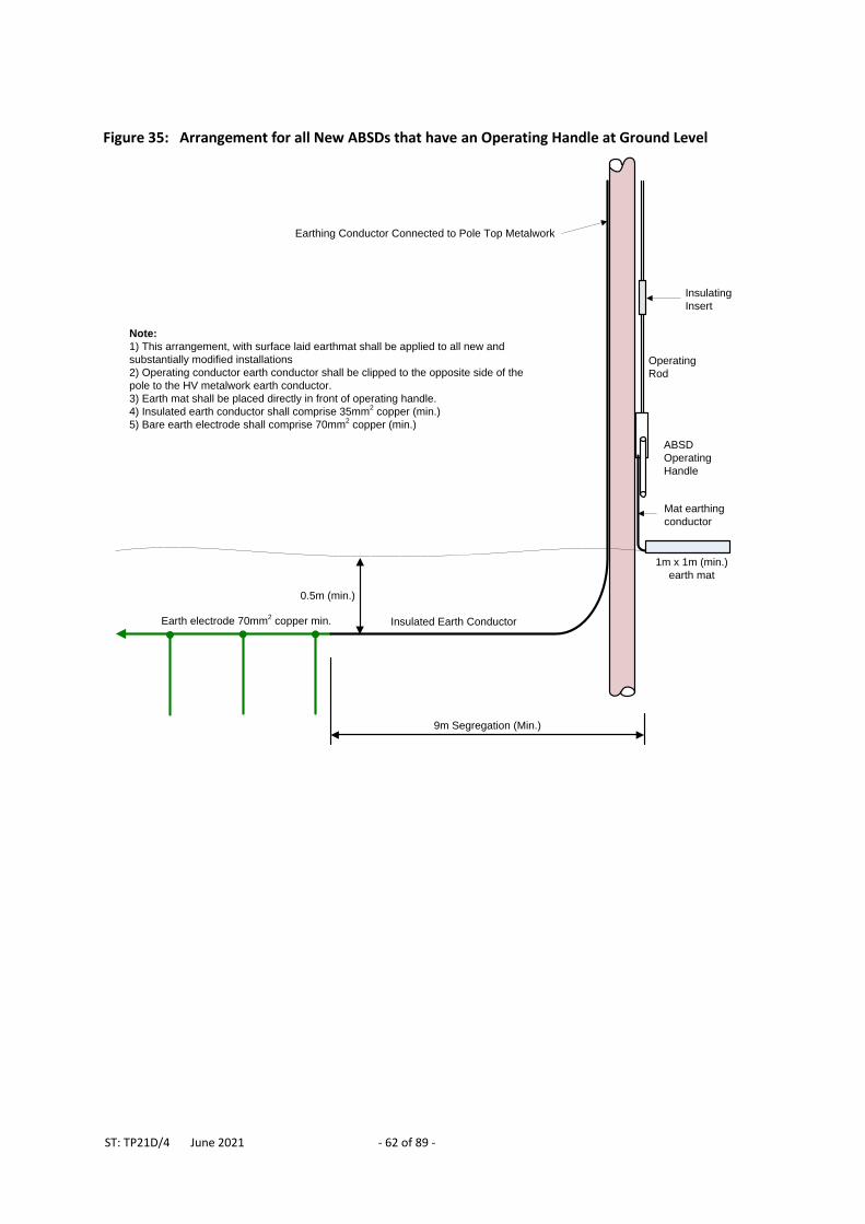
ST: TP21D/4 June 2021 - 62 of 89 -
Figure 35: Arrangement for all New ABSDs that have an Operating Handle at Ground Level
Insulated Earth Conductor
ABSD
Operating
Handle
Insulating
Insert
Operating
Rod
Earthing Conductor Connected to Pole Top Metalwork
9m Segregation (Min.)
Note:
1) This arrangement, with surface laid earthmat shall be applied to all new and
substantially modified installations
2) Operating conductor earth conductor shall be clipped to the opposite side of the
pole to the HV metalwork earth conductor.
3) Earth mat shall be placed directly in front of operating handle.
4) Insulated earth conductor shall comprise 35mm2 copper (min.)
5) Bare earth electrode shall comprise 70mm2 copper (min.)
1m x 1m (min.)
earth mat
Mat earthing
conductor
Earth electrode 70mm2 copper min.
0.5m (min.)
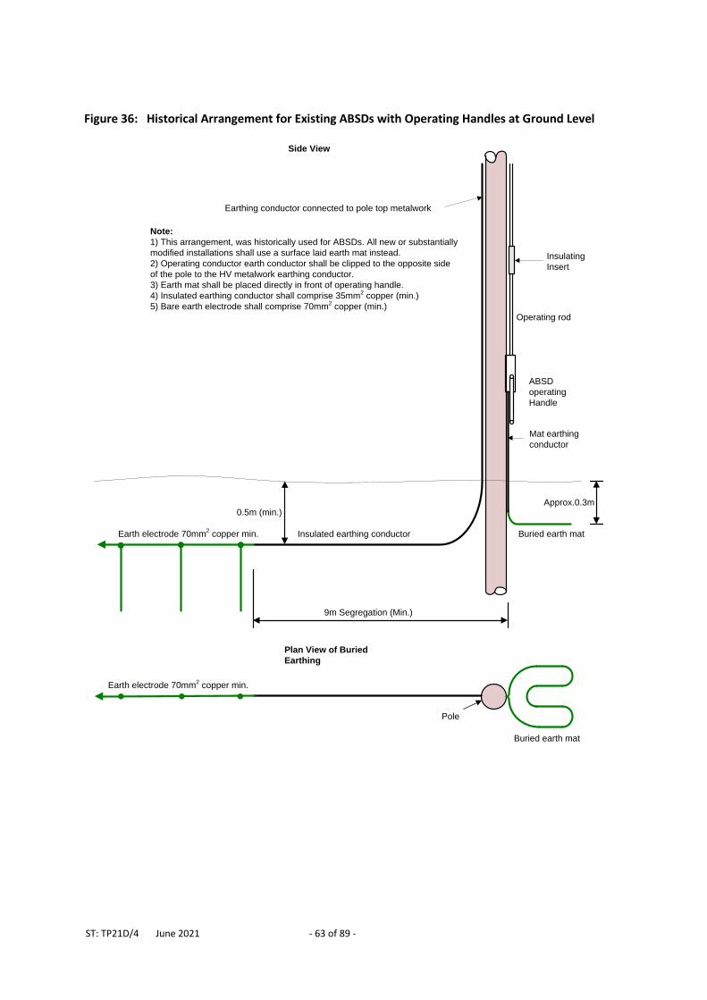
ST: TP21D/4 June 2021 - 63 of 89 -
Figure 36: Historical Arrangement for Existing ABSDs with Operating Handles at Ground Level
Insulated earthing conductor
ABSD
operating
Handle
Insulating
Insert
Operating rod
Earthing conductor connected to pole top metalwork
9m Segregation (Min.)
Note:
1) This arrangement, was historically used for ABSDs. All new or substantially
modified installations shall use a surface laid earth mat instead.
2) Operating conductor earth conductor shall be clipped to the opposite side
of the pole to the HV metalwork earthing conductor.
3) Earth mat shall be placed directly in front of operating handle.
4) Insulated earthing conductor shall comprise 35mm2 copper (min.)
5) Bare earth electrode shall comprise 70mm2 copper (min.)
Buried earth mat
Mat earthing
conductor
Approx.0.3m
Plan View of Buried
Earthing
Pole
Earth electrode 70mm2 copper min.
Buried earth mat
Earth electrode 70mm2 copper min.
Side View
0.5m (min.)
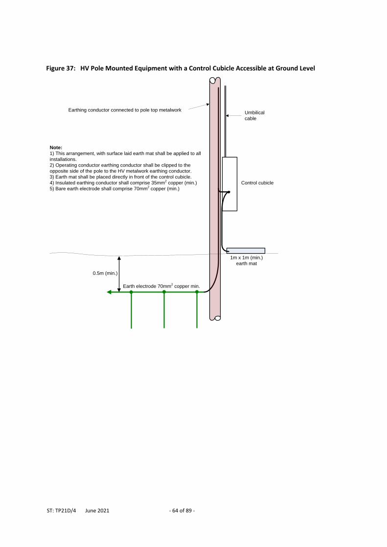
ST: TP21D/4 June 2021 - 64 of 89 -
Figure 37: HV Pole Mounted Equipment with a Control Cubicle Accessible at Ground Level
Control cubicle
Umbilical
cable
Earthing conductor connected to pole top metalwork
Note:
1) This arrangement, with surface laid earth mat shall be applied to all
installations.
2) Operating conductor earthing conductor shall be clipped to the
opposite side of the pole to the HV metalwork earthing conductor.
3) Earth mat shall be placed directly in front of the control cubicle.
4) Insulated earthing conductor shall comprise 35mm2 copper (min.)
5) Bare earth electrode shall comprise 70mm2 copper (min.)
1m x 1m (min.)
earth mat
Earth electrode 70mm2 copper min.
0.5m (min.)
ST: TP21D/4 June 2021 - 65 of 89 -
5.9 HV Cables All HV cables have a continuous metallic screen and this screen must be maintained through all joints and terminations. The screen shall be connected to earth at both ends of the cable in accordance with POL: CA6, unless otherwise agreed by the Policy Section. When cables are terminated within switchgear, a bond must be connected between the cable screen and the switchgear HV earth bar, taking into account any special requirements for frame leakage busbar protection, CTs (e.g. core balance CTs), and earth fault passage indicators. It is not acceptable to just rely on the fortuitous connection between the cable gland and switchgear metalwork. Further guidance is provided in the ST: CA2 series of company directives, and also in ST: CA6B and ST: SP1FC. Traditional paper insulated, lead covered (PILC) cables have a hessian serving which, after installation, provides a good electrical contact between the cable armouring and screen to earth. Where such cables are widely used they significantly reduce substation earth resistance values. This is particularly beneficial in reducing the rise of earth potential that can occur at primary substations. Modern cables have an insulating serving (typically PVC or XLPE) and therefore they do not contribute to substation earthing systems. As PILC cable is replaced with new cable the earth resistance values in urban areas are likely to rise unless steps are taken to prevent this. Given this, whenever 100m or more of HV PILC cable is to be disconnected and the severed section is located wholly or partially within a 400m radius of a primary substation, then bare 70mm2 copper conductor shall be laid in parallel with any newly installed HV cable and bonded to the cable screen at the end which is electrically closest to the primary substation in accordance with ST: CA2W. The bare copper conductor shall extend to the far end of the new HV cable or for 200m, whichever is the lesser. Where the bare copper conductor enters or exits a substation it shall alternatively be bonded to the substation’s HV earthing system. Where the primary substation is a hot site the installer shall notify Primary System Design to give them the opportunity to re-assess the need for the bare copper conductor.
6 LV EARTHING
6.1 System Earthing Requirements for earthing the LV side of distribution transformers are specified in sections 5.4 to 5.6 inclusive, and the statutory requirements for LV earthing are discussed in Section 3.1. The LV system shall either comprise of a combined neutral and earth (CNE) system, where a single conductor provides both the neutral and protective (earthing) functions, as a separate neutral and earth system (SNE) where the neutral and protective functions are provided by two separate conductors or as a mixed CNE and SNE system. The type of earthing that may be provided to customers depend on the LV system earthing arrangement, LV earth resistance and the nature of the customer’s installation. The various types of customer earthing are listed below:
Protective Multiple Earthing (PME) Protective Neutral Bonding (PNB) Separate Neutral and Earth (SNE)
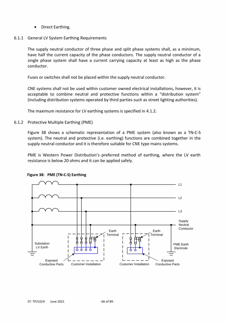
ST: TP21D/4 June 2021 - 66 of 89 -
Direct Earthing.
6.1.1 General LV System Earthing Requirements The supply neutral conductor of three phase and split phase systems shall, as a minimum, have half the current capacity of the phase conductors. The supply neutral conductor of a single phase system shall have a current carrying capacity at least as high as the phase conductor. Fuses or switches shall not be placed within the supply neutral conductor. CNE systems shall not be used within customer owned electrical installations, however, it is acceptable to combine neutral and protective functions within a “distribution system” (including distribution systems operated by third parties such as street lighting authorities). The maximum resistance for LV earthing systems is specified in 4.1.2.
6.1.2 Protective Multiple Earthing (PME)
Figure 38 shows a schematic representation of a PME system (also known as a TN-C-S system). The neutral and protective (i.e. earthing) functions are combined together in the supply neutral conductor and it is therefore suitable for CNE type mains systems. PME is Western Power Distribution’s preferred method of earthing, where the LV earth resistance is below 20 ohms and it can be applied safely.
Figure 38: PME (TN-C-S) Earthing
Customer Installation Customer InstallationExposed
Conductive Parts
Exposed
Conductive Parts
PME Earth
Electrode
Substation
LV Earth
Earth
Terminal
Earth
Terminal
L1
L2
L3
Supply
Neutral
Conductor
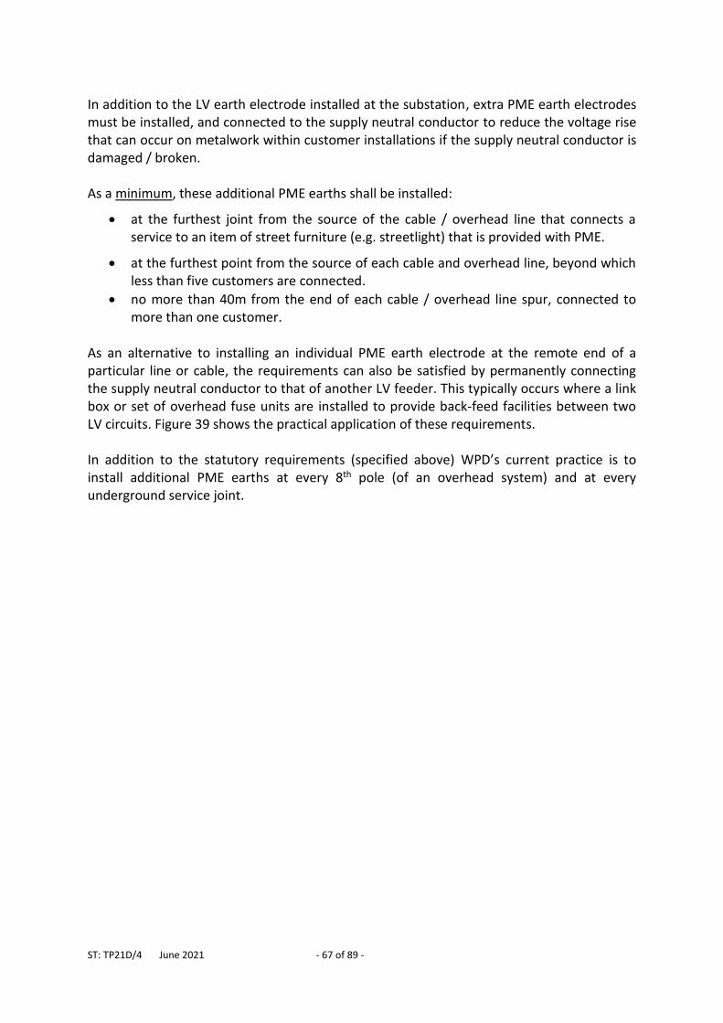
ST: TP21D/4 June 2021 - 67 of 89 -
In addition to the LV earth electrode installed at the substation, extra PME earth electrodes must be installed, and connected to the supply neutral conductor to reduce the voltage rise that can occur on metalwork within customer installations if the supply neutral conductor is damaged / broken. As a minimum, these additional PME earths shall be installed:
at the furthest joint from the source of the cable / overhead line that connects a service to an item of street furniture (e.g. streetlight) that is provided with PME.
at the furthest point from the source of each cable and overhead line, beyond which less than five customers are connected.
no more than 40m from the end of each cable / overhead line spur, connected to more than one customer.
As an alternative to installing an individual PME earth electrode at the remote end of a particular line or cable, the requirements can also be satisfied by permanently connecting the supply neutral conductor to that of another LV feeder. This typically occurs where a link box or set of overhead fuse units are installed to provide back-feed facilities between two LV circuits. Figure 39 shows the practical application of these requirements. In addition to the statutory requirements (specified above) WPD’s current practice is to install additional PME earths at every 8th pole (of an overhead system) and at every underground service joint.
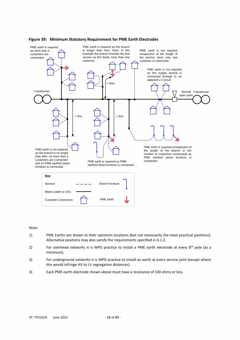
ST: TP21D/4 June 2021 - 68 of 89 -
Note:
1) PME Earths are shown at their optimum locations (but not necessarily the most practical positions). Alternative positions may also satisfy the requirements specified in 6.1.2.
2) For overhead networks it is WPD practice to install a PME earth electrode at every 8th pole (as a minimum).
3) For underground networks it is WPD practice to install an earth at every service joint (except where this would infringe HV to LV segregation distances).
4) Each PME earth electrode shown above must have a resistance of 100 ohms or less.
Figure 39: Minimum Statutory Requirement for PME Earth Electrodes
≤ 40m
PME earth is not required
as the branch is no longer
than 40m, no more than 4
customers are connected
and no PME earthed street
furniture is connected.
PME earth is required as the branch
is longer than 40m. Note, in this
example the branch includes the first
service as this feeds more than one
customer.
PME earth is not required
irrespective of the length of
the service since only one
customer is connected.
PME earth is required
as more than 4
customers are
connected.
PME earth is not required
as the supply neutral is
connected through to an
adjacent LV circuit.
Normal
open point
Transformer
PME earth is required as PME
earthed street furniture is connected.
> 40m
≤ 40m
PME earth is required (irrespective of
the length of the branch or the
number of customers connected) as
PME earthed street furniture is
connected.
Transformer
Key:
Service:
Mains (cable or o/h):
Customer Connection:
Street Furniture:
PME earth:
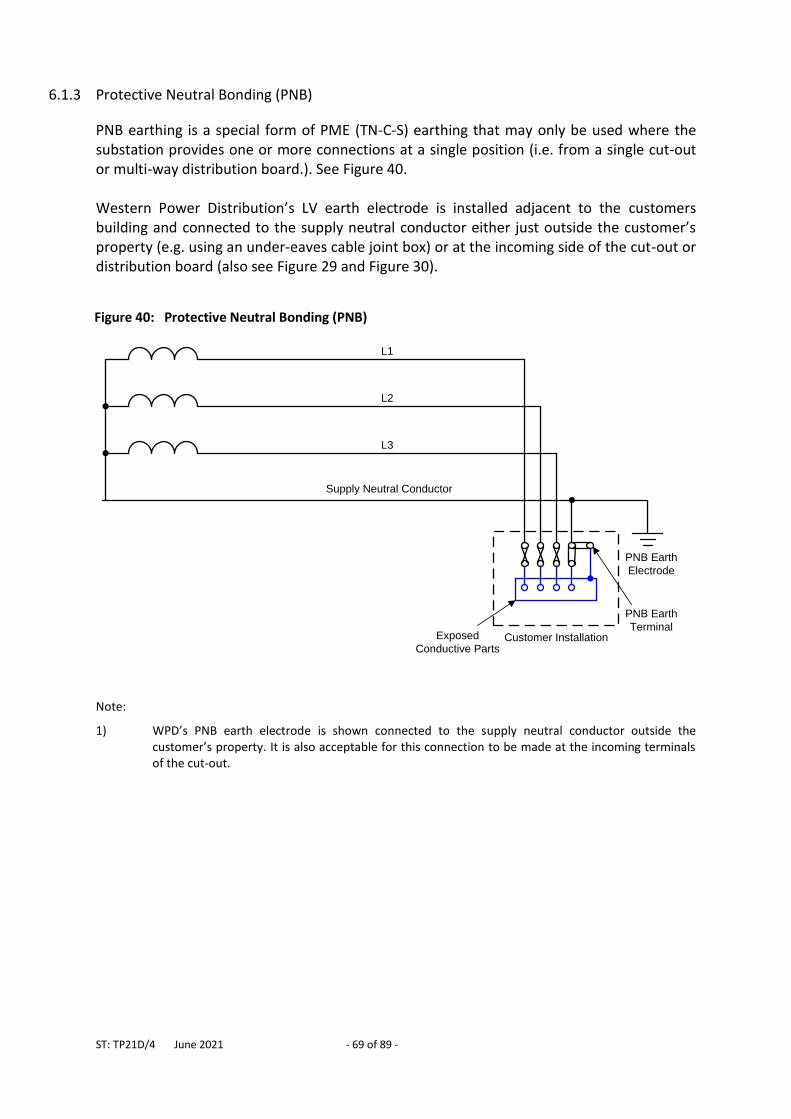
ST: TP21D/4 June 2021 - 69 of 89 -
6.1.3 Protective Neutral Bonding (PNB)
PNB earthing is a special form of PME (TN-C-S) earthing that may only be used where the substation provides one or more connections at a single position (i.e. from a single cut-out or multi-way distribution board.). See Figure 40. Western Power Distribution’s LV earth electrode is installed adjacent to the customers building and connected to the supply neutral conductor either just outside the customer’s property (e.g. using an under-eaves cable joint box) or at the incoming side of the cut-out or distribution board (also see Figure 29 and Figure 30).
Note:
1) WPD’s PNB earth electrode is shown connected to the supply neutral conductor outside the customer’s property. It is also acceptable for this connection to be made at the incoming terminals of the cut-out.
Figure 40: Protective Neutral Bonding (PNB)
Exposed
Conductive Parts
PNB Earth
Electrode
PNB Earth
Terminal
L1
L2
L3
Supply Neutral Conductor
Customer Installation
ST: TP21D/4 June 2021 - 70 of 89 -
6.1.4 Separate Neutral and Earth (SNE)
Cable Sheath Earthing and Separate Continuous Aerial Earth Wire systems are both known as SNE (or TN-S) earthing. These systems were commonly used prior to the introduction of PME. See Figure 41. Cable sheath earthing is used where separate neutral and earth cables are installed (e.g. 3 phase 4 core cables and single phase split concentric cables). Continuous Arial Earth Wire systems may be applied to open wire overhead lines and to aerial bundled conductor (ABC) lines (where an additional earth wire is installed). Although SNE is not the preferred earthing arrangement it may still be installed or retained where PME is not suitable.
PME cannot provided on the grounds of safety or where it is not reasonably practicable to satisfy the criteria for PME the LV earthing system criteria for providing PME cannot be satisfied. but applicable to overhead lines
Figure 41: Separate Neutral and Earth (SNE)
Customer InstallationExposed
Conductive Parts
Exposed
Conductive Parts
Substation
LV Earth
Earth
Terminal
Earth
Terminal
L1
L2
L3
Supply
Neutral
Conductor
Customer Installation
Earth
Conductor
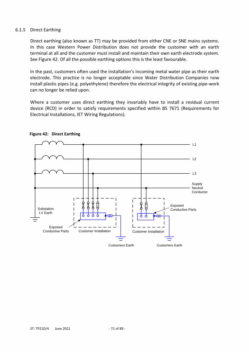
ST: TP21D/4 June 2021 - 71 of 89 -
6.1.5 Direct Earthing
Direct earthing (also known as TT) may be provided from either CNE or SNE mains systems. In this case Western Power Distribution does not provide the customer with an earth terminal at all and the customer must install and maintain their own earth electrode system. See Figure 42. Of all the possible earthing options this is the least favourable. In the past, customers often used the installation’s incoming metal water pipe as their earth electrode. This practice is no longer acceptable since Water Distribution Companies now install plastic pipes (e.g. polyethylene) therefore the electrical integrity of existing pipe-work can no longer be relied upon. Where a customer uses direct earthing they invariably have to install a residual current device (RCD) in order to satisfy requirements specified within BS 7671 (Requirements for Electrical Installations, IET Wiring Regulations).
Figure 42: Direct Earthing
Customer InstallationExposed
Conductive Parts
Exposed
Conductive PartsSubstation
LV Earth
L1
L2
L3
Supply
Neutral
Conductor
Customer Installation
Customers Earth Customers Earth
ST: TP21D/4 June 2021 - 72 of 89 -
6.2 Provision of SNE and PME Earthing Terminals
Western Power Distribution have a legal obligation under the Electricity Safety, Quality and Continuity Regulations 2004 to offer an earthing terminal when providing a new connection at low voltage, unless it is unsafe to do so. In such cases it is acceptable to provide customers with PME, SNE or PNB type earthing terminals, although PME is the preferred option where it can be provided safely. If the cost of providing a PME, SNE or PNB earth terminal is prohibitive the customer should be given the option to choose direct earthing, if they wish. There is no legal obligation on Distribution Companies to provide an earth terminal at existing installations (e.g. when renewing or moving a service) but earth terminals should be provided, on request, where it is technically and economically acceptable to WPD. Further details are provided in ST: TP21E. The nature of the mains system, e.g. whether it is combined neutral and earth (CNE) or a separate neutral and earth (SNE), has a significant bearing on the provision of PME and SNE earth terminals. The following types of system are considered:
CNE mains system designed for PME connections.
SNE mains system that has not been converted for PME connections.
SNE mains system that has been converted for PME connections.
Mixed CNE / SNE mains system that has been converted for PME connections.
6.2.1 CNE Mains System designed for PME Connections
New systems installed by WPD are normally constructed using cables and overhead lines with combined neutral and earth conductors (e.g. 3 core wavecon cable and aerial bundled conductor (ABC) overhead lines). Customers shall be offered a PME earth terminal by default, as long as:
the LV resistance is 20 ohms or below
it is safe and economic to do so SNE earth terminals may be provided where there is an earth electrode beyond the connection (i.e. further from the source substation than the position of the connection) has a resistance of 10 ohms or less. If the above requirements are not met and it is unsafe to provide PME (due to the type of installation, its electrical design or due to inadequate bonding) direct earthing shall be provided instead (see Figure 43). Further guidance on customer earthing is provided in ST: TP21E.
ST: TP21D/4 June 2021 - 73 of 89 -
6.2.2 SNE Systems that HAVE NOT been designed or modified for PME earthing
Historically LV systems were constructed using SNE cables and/or overhead lines. Many of these have since been modified to allow PME earthing to be provided (e.g. PME earth electrodes installed). Where these modifications have not been carried out, and it is not practical or economic to do so, new customers shall be offered SNE earthing as standard. PME earthing is not available. (See Figure 44).
6.2.3 SNE Systems that HAVE been modified for PME earthing Many SNE system have been converted to allow PME earth terminals to be provided to customers. The type of customer earthing that may be offered (or retained) in such circumstances is specified in Figure 45.
6.2.4 Mixed SNE and CNE systems As existing SNE LV systems are extended, augmented and replaced this is usually carried out using CNE type cable or overhead line. The type of customer earthing that can be offered or retained in these circumstances is shown in Figure 46 and Figure 47.
6.2.5 Service Cables / Overhead Lines The type of service that is installed (CNE or SNE) is determined by the earthing facilities at the connection. Whenever a length of service cable is laid into an existing service (e.g. to repair a fault) the same type of cable shall be used. Table 8 summarises these requirements. Where services are looped the requirements listed in Table 8 apply to the entire route of the service (i.e. from the associated customer cut-out to the mains joint / termination).
Table 8: Service Cable Requirements
Customer Earthing Facility Service Type
PME CNE service is preferred
Existing SNE service cable / line may be retained
SNE
SNE service cable / line (from the associated cut-out back to the mains joint / termination) is required.
CNE service is not acceptable.
Direct Earthing (customer installs own earth terminal)
CNE service is preferred
Existing SNE service cable / line may be retained
ST: TP21D/4 June 2021 - 74 of 89 -
6.2.6 Charging Arrangements for Providing or Modifying Earth Terminals
As a general principle, the person or organisation who requests an earth terminal or who initiates work that causes modifications to be made to the earthing system, shall pay all the associated earthing costs. For example, where a new connection is requested the earthing costs shall be included within the connection charge. If changes are proposed that require existing SNE customers to convert to PME or Direct Earthing, Western Power Distribution shall inform these customers and make arrangements for a suitably qualified electrical installer to check the installations and to carry out any required modifications. The costs associated with this work shall be paid for by Western Power Distribution and not by the affected customers. Where these earthing changes are due to a new business scheme, augmentation or a diversion the costs should be passed on to person / organisation that initiated the work.
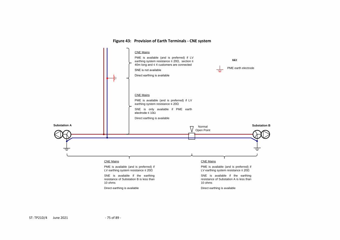
ST: TP21D/4 June 2021 - 75 of 89 -
Figure 43: Provision of Earth Terminals - CNE system
Substation A Normal
Open Point
CNE Mains
PME is available (and is preferred) if LV
earthing system resistance ≤ 20Ω, section ≤
40m long and ≤ 4 customers are connected
SNE is not available
Direct earthing is available
CNE Mains
PME is available (and is preferred) if LV
earthing system resistance ≤ 20Ω
SNE is only available if PME earth
electrode ≤ 10Ω
Direct earthing is available
CNE Mains
PME is available (and is preferred) if
LV earthing system resistance ≤ 20Ω
SNE is available if the earthing
resistance of Substation B is less than
10 ohms
Direct earthing is available
Substation B
CNE Mains
PME is available (and is preferred) if
LV earthing system resistance ≤ 20Ω
SNE is available if the earthing
resistance of Substation A is less than
10 ohms
Direct earthing is available
PME earth electrode
KEY
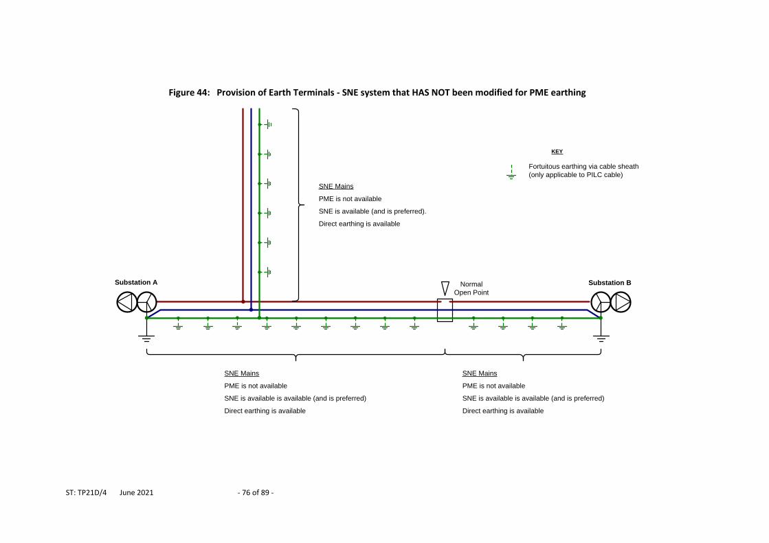
ST: TP21D/4 June 2021 - 76 of 89 -
Figure 44: Provision of Earth Terminals - SNE system that HAS NOT been modified for PME earthing
Substation A Normal
Open Point
Substation B
Fortuitous earthing via cable sheath
(only applicable to PILC cable)
KEY
SNE Mains
PME is not available
SNE is available (and is preferred).
Direct earthing is available
SNE Mains
PME is not available
SNE is available is available (and is preferred)
Direct earthing is available
SNE Mains
PME is not available
SNE is available is available (and is preferred)
Direct earthing is available
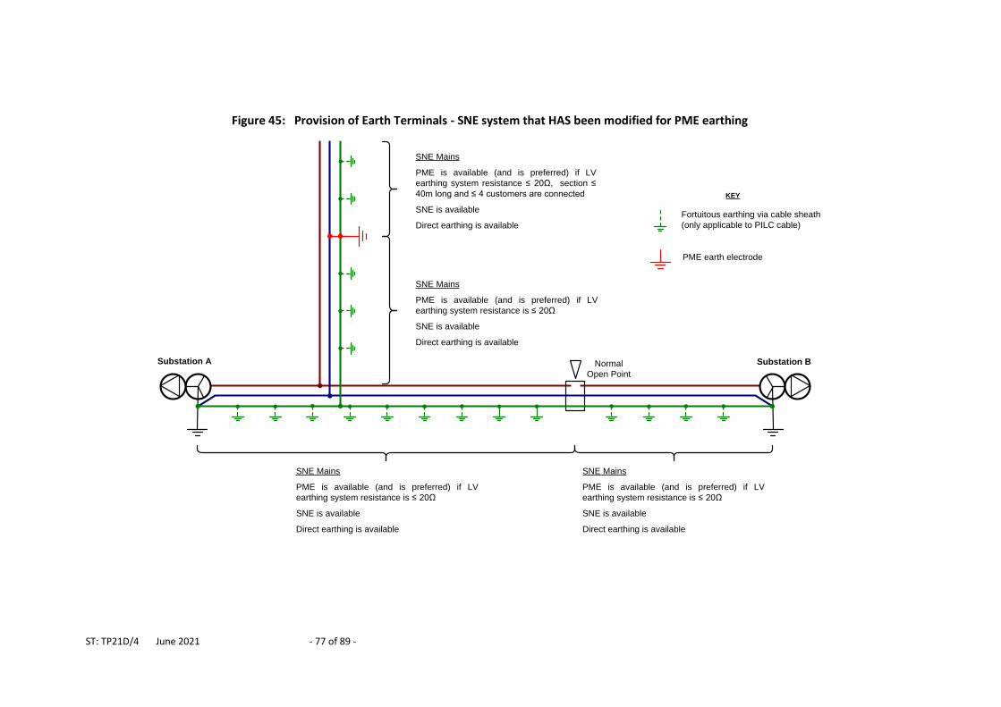
ST: TP21D/4 June 2021 - 77 of 89 -
Figure 45: Provision of Earth Terminals - SNE system that HAS been modified for PME earthing
Substation A Normal
Open Point
Substation B
Fortuitous earthing via cable sheath
(only applicable to PILC cable)
PME earth electrode
KEY
SNE Mains
PME is available (and is preferred) if LV
earthing system resistance ≤ 20Ω, section ≤
40m long and ≤ 4 customers are connected
SNE is available
Direct earthing is available
SNE Mains
PME is available (and is preferred) if LV
earthing system resistance is ≤ 20Ω
SNE is available
Direct earthing is available
SNE Mains
PME is available (and is preferred) if LV
earthing system resistance is ≤ 20Ω
SNE is available
Direct earthing is available
SNE Mains
PME is available (and is preferred) if LV
earthing system resistance is ≤ 20Ω
SNE is available
Direct earthing is available
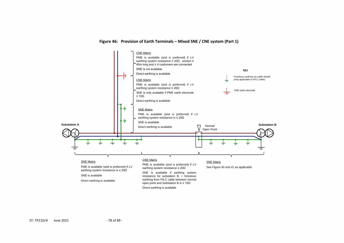
ST: TP21D/4 June 2021 - 78 of 89 -
Figure 46: Provision of Earth Terminals – Mixed SNE / CNE system (Part 1)
Substation A Normal
Open Point
Substation B
Fortuitous earthing via cable sheath
(only applicable to PILC cable)
PME earth electrode
KEY
SNE Mains
PME is available (and is preferred) if LV
earthing system resistance is ≤ 20Ω
SNE is available
Direct earthing is available
SNE Mains
PME is available (and is preferred) if LV
earthing system resistance is ≤ 20Ω
SNE is available
Direct earthing is available.
SNE Mains
See Figure 40 and 41 as applicable
CNE Mains
PME is available (and is preferred) if LV
earthing system resistance ≤ 20Ω, section ≤
40m long and ≤ 4 customers are connected
SNE is not available
Direct earthing is available
CNE Mains
PME is available (and is preferred) if LV
earthing system resistance ≤ 20Ω
SNE is only available if PME earth electrode
≤ 10Ω
Direct earthing is available
CNE Mains
PME is available (and is preferred) if LV
earthing system resistance ≤ 20Ω
SNE is available if earthing system
resistance for substation B, + fortuitous
earthing from PILC cable between normal
open point and Substation B is ≤ 10Ω
Direct earthing is available
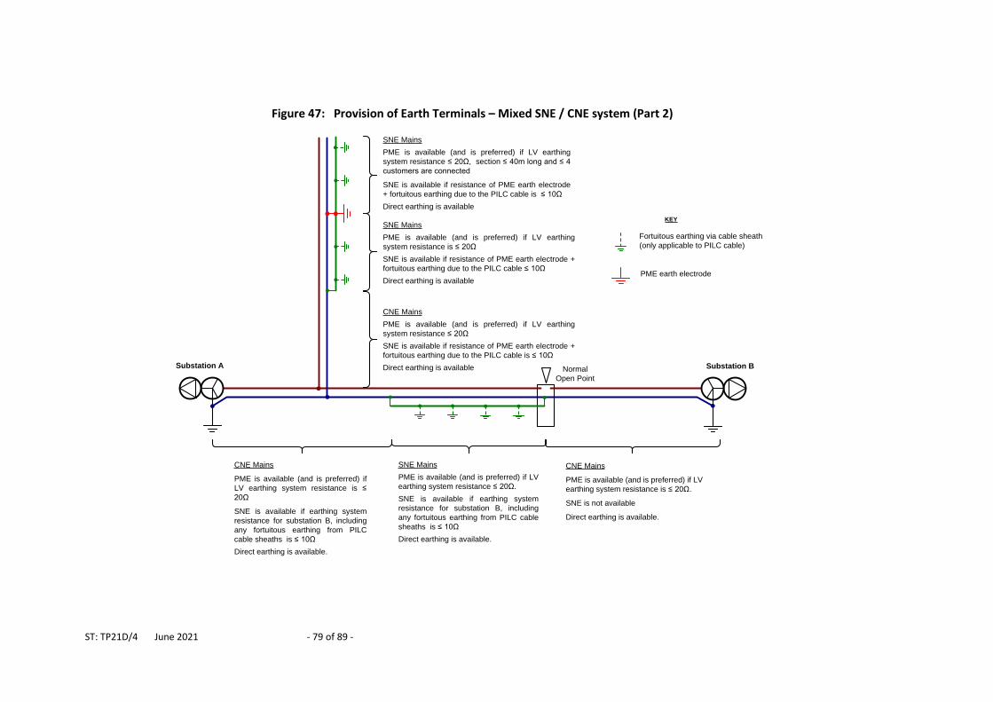
ST: TP21D/4 June 2021 - 79 of 89 -
Figure 47: Provision of Earth Terminals – Mixed SNE / CNE system (Part 2)
Substation A Normal
Open Point
Substation B
Fortuitous earthing via cable sheath
(only applicable to PILC cable)
PME earth electrode
KEY
CNE Mains
PME is available (and is preferred) if
LV earthing system resistance is ≤
20Ω
SNE is available if earthing system
resistance for substation B, including
any fortuitous earthing from PILC
cable sheaths is ≤ 10Ω
Direct earthing is available.
CNE Mains
PME is available (and is preferred) if LV
earthing system resistance is ≤ 20Ω.
SNE is not available
Direct earthing is available.
SNE Mains
PME is available (and is preferred) if LV earthing
system resistance ≤ 20Ω, section ≤ 40m long and ≤ 4
customers are connected
SNE is available if resistance of PME earth electrode
+ fortuitous earthing due to the PILC cable is ≤ 10Ω
Direct earthing is available
CNE Mains
PME is available (and is preferred) if LV earthing
system resistance ≤ 20Ω
SNE is available if resistance of PME earth electrode +
fortuitous earthing due to the PILC cable is ≤ 10Ω
Direct earthing is available
SNE Mains
PME is available (and is preferred) if LV
earthing system resistance ≤ 20Ω.
SNE is available if earthing system
resistance for substation B, including
any fortuitous earthing from PILC cable
sheaths is ≤ 10Ω
Direct earthing is available.
SNE Mains
PME is available (and is preferred) if LV earthing
system resistance is ≤ 20Ω
SNE is available if resistance of PME earth electrode +
fortuitous earthing due to the PILC cable ≤ 10Ω
Direct earthing is available
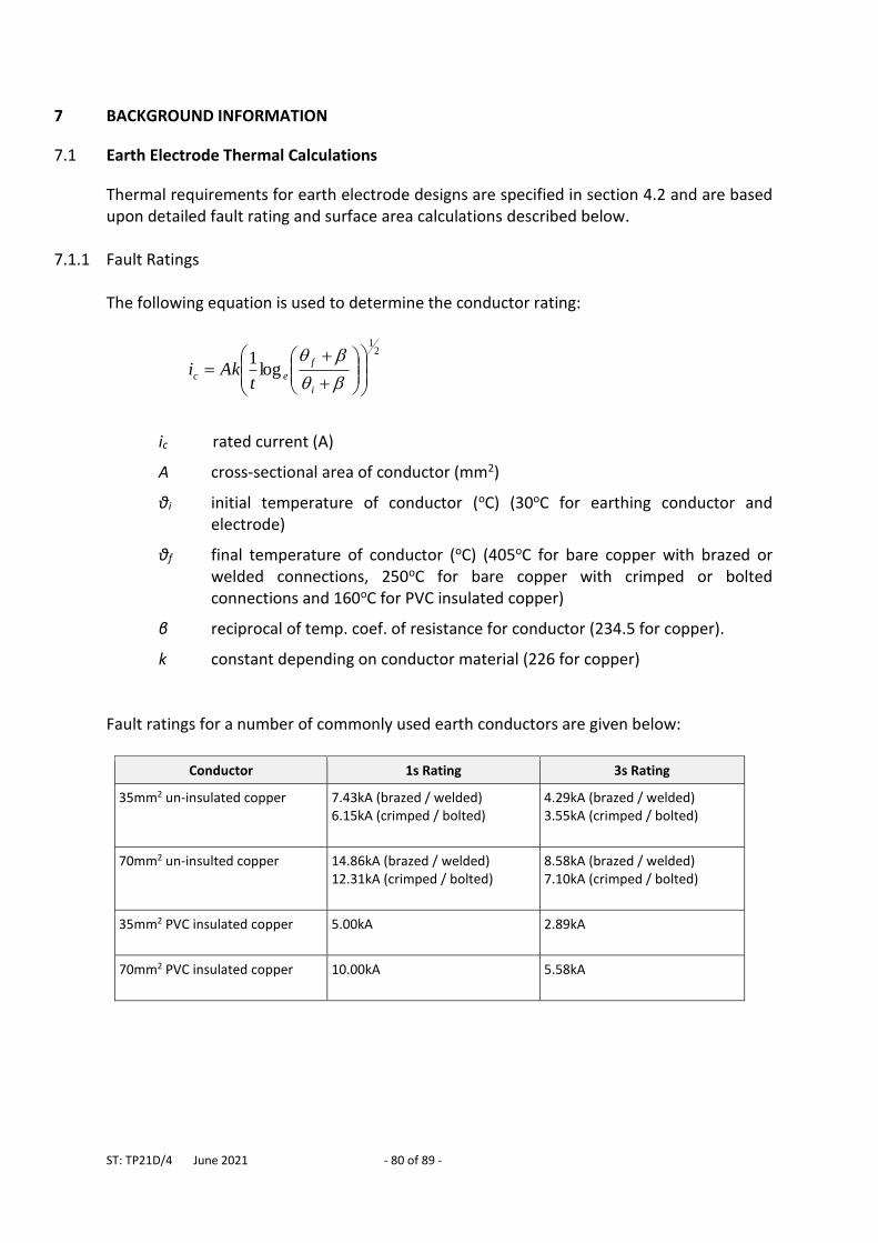
ST: TP21D/4 June 2021 - 80 of 89 -
7 BACKGROUND INFORMATION
7.1 Earth Electrode Thermal Calculations
Thermal requirements for earth electrode designs are specified in section 4.2 and are based upon detailed fault rating and surface area calculations described below.
7.1.1 Fault Ratings The following equation is used to determine the conductor rating:
21
log1
i
f
ect
Aki
ic rated current (A)
A cross-sectional area of conductor (mm2)
θi initial temperature of conductor (oC) (30oC for earthing conductor and electrode)
θf final temperature of conductor (oC) (405oC for bare copper with brazed or welded connections, 250oC for bare copper with crimped or bolted connections and 160oC for PVC insulated copper)
β reciprocal of temp. coef. of resistance for conductor (234.5 for copper).
k constant depending on conductor material (226 for copper)
Fault ratings for a number of commonly used earth conductors are given below:
Conductor 1s Rating 3s Rating
35mm2 un-insulated copper
7.43kA (brazed / welded) 6.15kA (crimped / bolted)
4.29kA (brazed / welded) 3.55kA (crimped / bolted)
70mm2 un-insulted copper
14.86kA (brazed / welded) 12.31kA (crimped / bolted)
8.58kA (brazed / welded) 7.10kA (crimped / bolted)
35mm2 PVC insulated copper
5.00kA 2.89kA
70mm2 PVC insulated copper
10.00kA 5.58kA
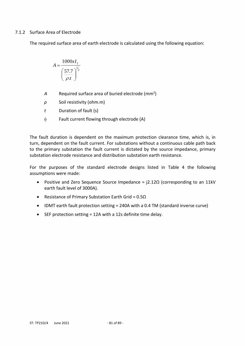
ST: TP21D/4 June 2021 - 81 of 89 -
7.1.2 Surface Area of Electrode
The required surface area of earth electrode is calculated using the following equation:
21
.
7.57
1000
t
xIA
f
A Required surface area of buried electrode (mm2)
ρ Soil resistivity (ohm.m)
t Duration of fault (s)
If Fault current flowing through electrode (A)
The fault duration is dependent on the maximum protection clearance time, which is, in turn, dependent on the fault current. For substations without a continuous cable path back to the primary substation the fault current is dictated by the source impedance, primary substation electrode resistance and distribution substation earth resistance. For the purposes of the standard electrode designs listed in Table 4 the following assumptions were made:
Positive and Zero Sequence Source Impedance = j2.12Ω (corresponding to an 11kV earth fault level of 3000A).
Resistance of Primary Substation Earth Grid = 0.5Ω
IDMT earth fault protection setting = 240A with a 0.4 TM (standard inverse curve)
SEF protection setting = 12A with a 12s definite time delay.
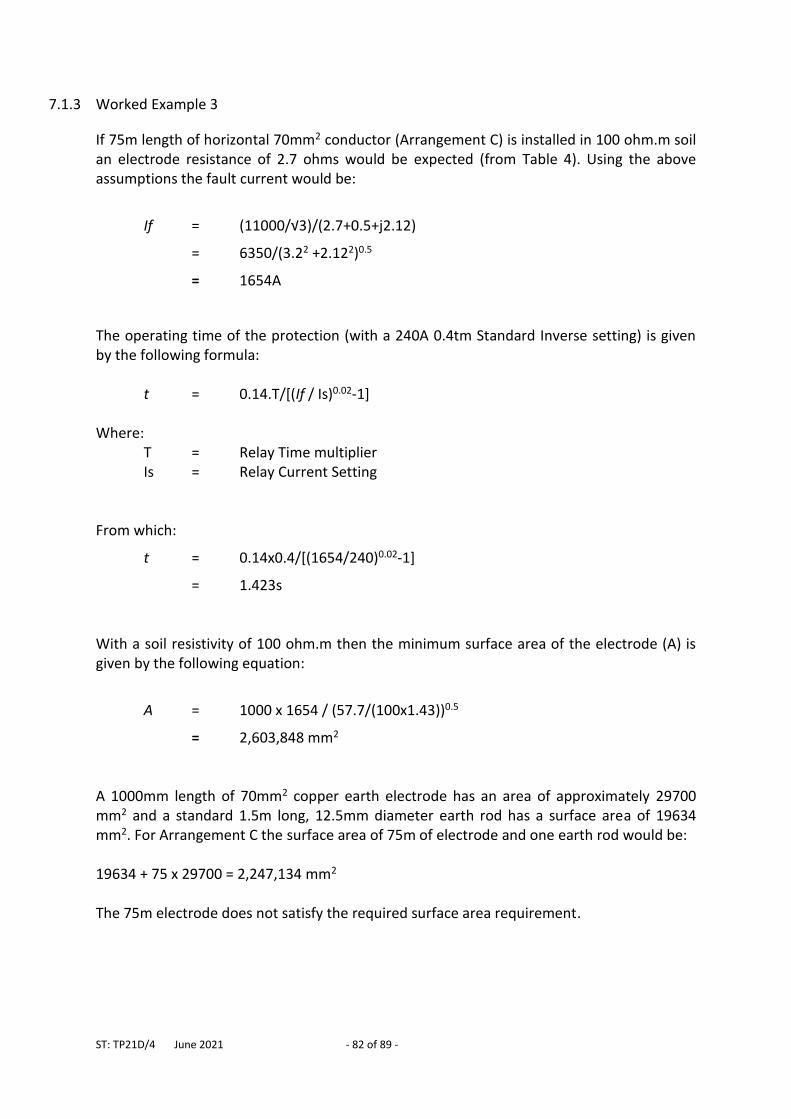
ST: TP21D/4 June 2021 - 82 of 89 -
7.1.3 Worked Example 3
If 75m length of horizontal 70mm2 conductor (Arrangement C) is installed in 100 ohm.m soil an electrode resistance of 2.7 ohms would be expected (from Table 4). Using the above assumptions the fault current would be:
If = (11000/√3)/(2.7+0.5+j2.12)
= 6350/(3.22 +2.122)0.5
= 1654A
The operating time of the protection (with a 240A 0.4tm Standard Inverse setting) is given by the following formula: t = 0.14.T/[(If / Is)0.02-1] Where: T = Relay Time multiplier Is = Relay Current Setting From which:
t = 0.14x0.4/[(1654/240)0.02-1]
= 1.423s With a soil resistivity of 100 ohm.m then the minimum surface area of the electrode (A) is given by the following equation:
A = 1000 x 1654 / (57.7/(100x1.43))0.5
= 2,603,848 mm2 A 1000mm length of 70mm2 copper earth electrode has an area of approximately 29700 mm2 and a standard 1.5m long, 12.5mm diameter earth rod has a surface area of 19634 mm2. For Arrangement C the surface area of 75m of electrode and one earth rod would be: 19634 + 75 x 29700 = 2,247,134 mm2 The 75m electrode does not satisfy the required surface area requirement.
ST: TP21D/4 June 2021 - 83 of 89 -
7.1.4 Worked Example 4
If the electrode in Worked Example 3 is extend to 100m:
electrode resistance would be 2.1 ohms (from Table 4)
fault current increases to 1893A *
protection clearance reduces to 1.32s *
required surface area of the electrode increases to 2,863,187 mm2 * The actual surface are of the 100m electrode is 2,989,634 mm2 and is sufficient for this application. * See Worked Example 3 for calculation method
7.2 HV And LV Earth Segregation Regulation 8. – (2) (b) of The Electricity Safety, Quality and Continuity Regulations 2002 imposes a duty on Distributors and Generators to ensure that “earth electrodes are designed, installed and used in such a manner so as to prevent danger occurring in any low voltage network as a result of any fault in the high voltage network”. Danger is defined as “danger to health or danger to life or limb from electric shock, burn, injury or mechanical movement to persons, livestock or domestic animals, or from fire, or explosion attendant upon the generation, transmission, distribution or use of energy. Section 3.2 demonstrates how rise of potential in earth electrode systems can give rise to hazardous step, touch and transfer potentials if not adequately controlled. The following diagrams show how faults in the HV system cause earth potential rise at a distribution substation. Figure 48 shows a fault on the HV side of a distribution transformer connected via overhead line. All the earth fault current flows through the distribution transformer’s earth electrode to return to the primary substation. This causes a high rise of potential (i.e. above 430V).
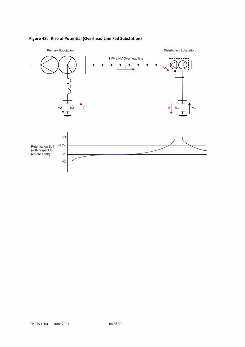
ST: TP21D/4 June 2021 - 84 of 89 -
Figure 48: Rise of Potential (Overhead Line Fed Substation)
If If
If
V2 V1
V2
V1
0
430V
Primary Substation
3 Wire HV Overhead line
Distribution Substation
R2 R1
Potential on Soil
(with respect to
remote earth)
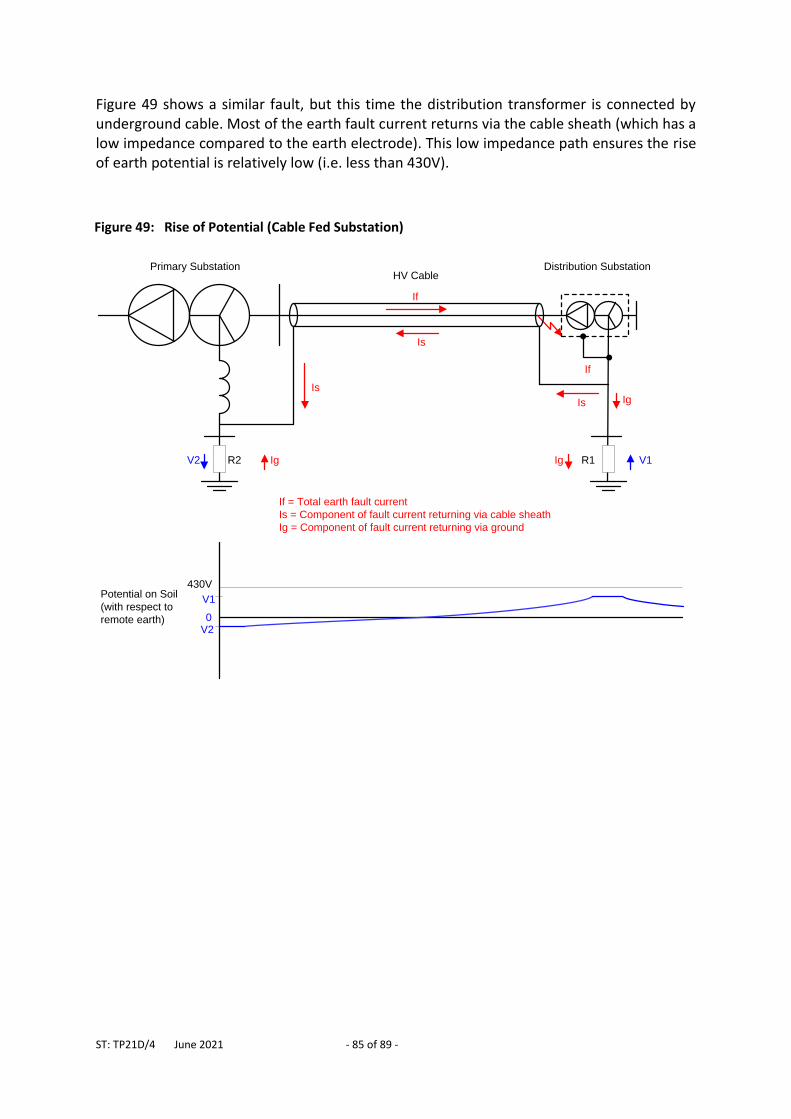
ST: TP21D/4 June 2021 - 85 of 89 -
Figure 49 shows a similar fault, but this time the distribution transformer is connected by underground cable. Most of the earth fault current returns via the cable sheath (which has a low impedance compared to the earth electrode). This low impedance path ensures the rise of earth potential is relatively low (i.e. less than 430V).
Figure 49: Rise of Potential (Cable Fed Substation)
Ig IgV2 V1
V2
V1
0
430V
Primary SubstationHV Cable
Distribution Substation
R2 R1
Is
Is
Is
If
If
Ig
If = Total earth fault current
Is = Component of fault current returning via cable sheath
Ig = Component of fault current returning via ground
Potential on Soil
(with respect to
remote earth)
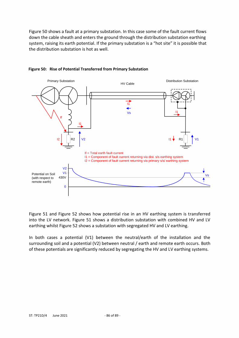
ST: TP21D/4 June 2021 - 86 of 89 -
Figure 50 shows a fault at a primary substation. In this case some of the fault current flows down the cable sheath and enters the ground through the distribution substation earthing system, raising its earth potential. If the primary substation is a “hot site” it is possible that the distribution substation is hot as well.
Figure 51 and Figure 52 shows how potential rise in an HV earthing system is transferred into the LV network. Figure 51 shows a distribution substation with combined HV and LV earthing whilst Figure 52 shows a substation with segregated HV and LV earthing. In both cases a potential (V1) between the neutral/earth of the installation and the surrounding soil and a potential (V2) between neutral / earth and remote earth occurs. Both of these potentials are significantly reduced by segregating the HV and LV earthing systems.
Figure 50: Rise of Potential Transferred from Primary Substation
I2 V2 V1
V2
V1
0
430V
Primary SubstationHV Cable
Distribution Substation
R2 R1
If
If = Total earth fault current
I1 = Component of fault current returning via dist. s/s earthing system
I2 = Component of fault current returning via primary s/s/ earthing system
I1
I1
I1
I1
Vs
VsPotential on Soil
(with respect to
remote earth)
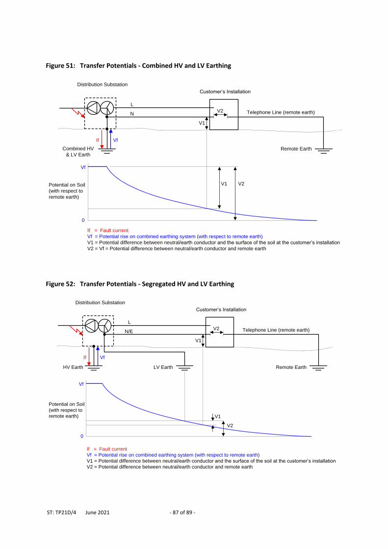
ST: TP21D/4 June 2021 - 87 of 89 -
Figure 52: Transfer Potentials - Segregated HV and LV Earthing
Distribution Substation
HV Earth
Telephone Line (remote earth)
V1
V2
V1
V2
Remote Earth
If Vf
Vf
L
N/E
0
Potential on Soil
(with respect to
remote earth)
If = Fault current
Vf = Potential rise on combined earthing system (with respect to remote earth)
V1 = Potential difference between neutral/earth conductor and the surface of the soil at the customer’s installation
V2 = Potential difference between neutral/earth conductor and remote earth
Customer’s Installation
LV Earth
Figure 51: Transfer Potentials - Combined HV and LV Earthing
Distribution Substation
Telephone Line (remote earth)
V1
V2
V1 V2
Remote Earth
If Vf
Vf
L
N
Customer’s Installation
Potential on Soil
(with respect to
remote earth)
0
If = Fault current
Vf = Potential rise on combined earthing system (with respect to remote earth)
V1 = Potential difference between neutral/earth conductor and the surface of the soil at the customer’s installation
V2 = Vf = Potential difference between neutral/earth conductor and remote earth
Combined HV
& LV Earth
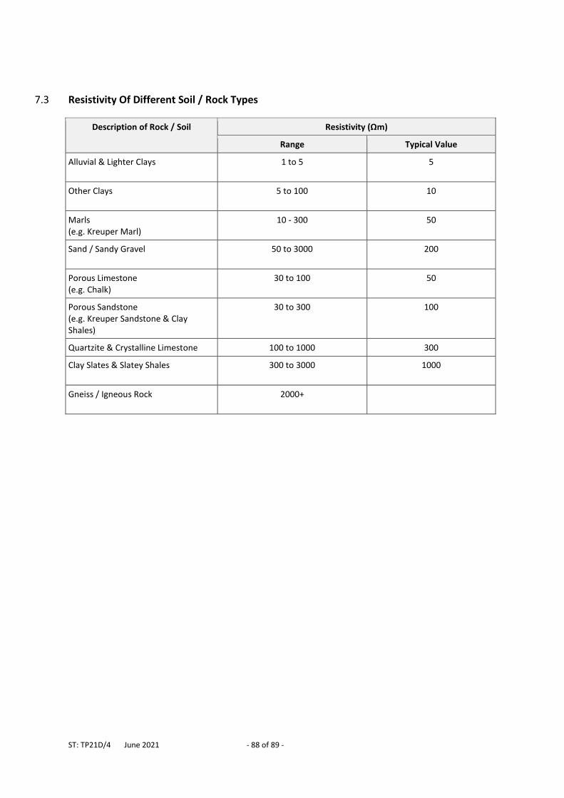
ST: TP21D/4 June 2021 - 88 of 89 -
7.3 Resistivity Of Different Soil / Rock Types
Description of Rock / Soil Resistivity (Ωm)
Range Typical Value
Alluvial & Lighter Clays
1 to 5 5
Other Clays
5 to 100 10
Marls (e.g. Kreuper Marl)
10 - 300 50
Sand / Sandy Gravel
50 to 3000 200
Porous Limestone (e.g. Chalk)
30 to 100 50
Porous Sandstone (e.g. Kreuper Sandstone & Clay Shales)
30 to 300 100
Quartzite & Crystalline Limestone 100 to 1000 300
Clay Slates & Slatey Shales
300 to 3000 1000
Gneiss / Igneous Rock
2000+
ST: TP21D/4 June 2021 - 89 of 89 -
APPENDIX A
SUPERSEDED DOCUMENTATION
This document supersedes ST: TP21D/3 dated March 2018 which has now been withdrawn.
APPENDIX B RECORD OF COMMENT DURING CONSULTATION No consultation as there were no changes.
APPENDIX C ANCILLARY DOCUMENTATION POL: TP12 Fixed Earthing Systems ST: TP21A Safety Limits for Touch and Step Voltages – Earthing System
Design/Assessment ST: TP21B Design and Installation of Fixed Earthing Systems - Major Substations ST: TP21E Provision of WPD Earth Terminals To Customer LV Installations ST: TP21L Fixed Earthing Systems - Construction Techniques - Jointing ST: TP21O Measurements Associated with Earthing Systems ENA Technical Specification 41-24; Guidelines for the Design, Installation, Testing and Maintenance of Main Earthing Systems in Substations. ENA Engineering Recommendation G12; Requirements for the Application of Protective Multiple earthing to Low Voltage networks. ENA Engineering Recommendation S34; A Guide for Assessing the Rise of Earth Potential at Substation Sites.
APPENDIX D KEYWORDS Earthing, Grounding, PME, SNE, PNB, Direct Earthing.