Embed Size (px)
Citation preview
第第 1 章章 概念概念
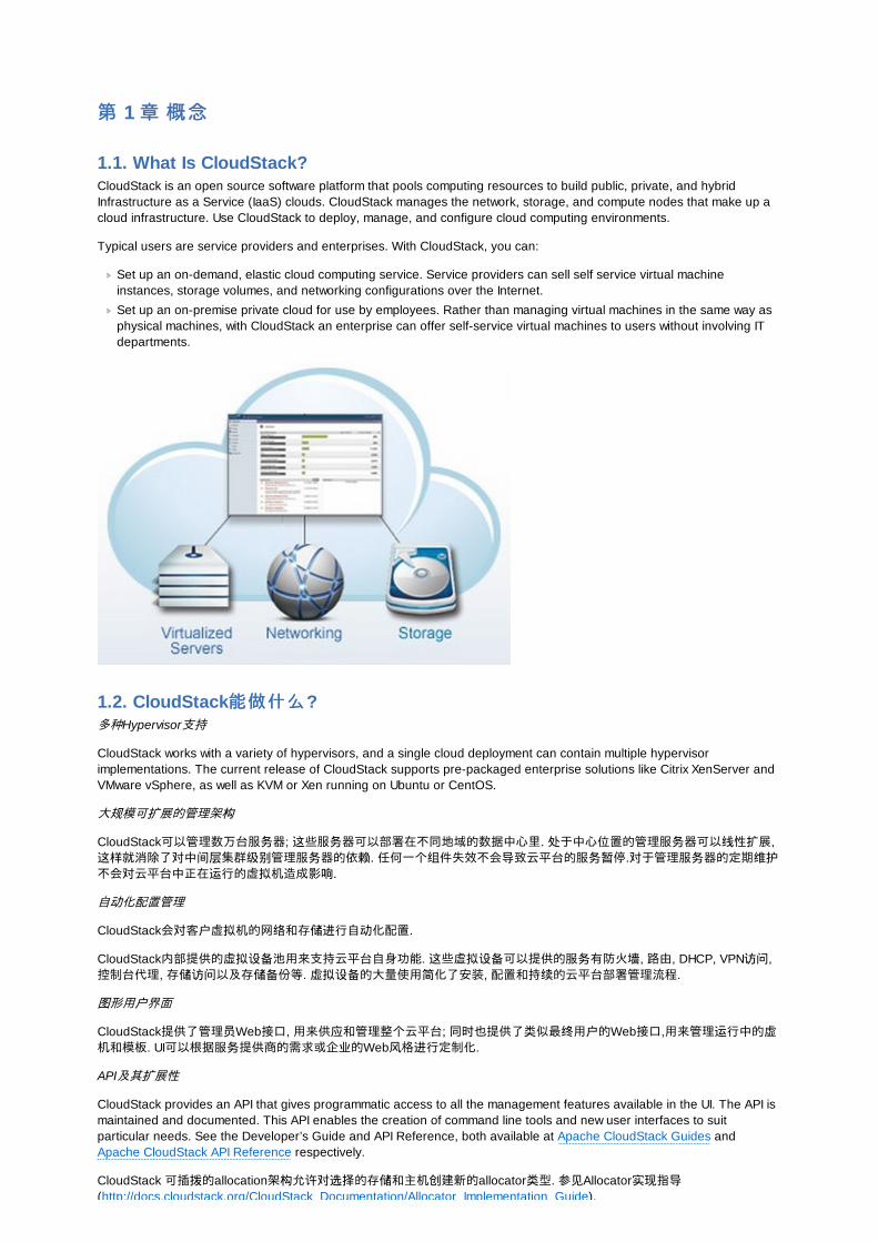
1.1. What Is CloudStack?CloudStack is an open source software platform that pools computing resources to build public, private, and hybridInfrastructure as a Service (IaaS) clouds. CloudStack manages the network, storage, and compute nodes that make up acloud infrastructure. Use CloudStack to deploy, manage, and configure cloud computing environments.
Typical users are service providers and enterprises. With CloudStack, you can:
Set up an on-demand, elastic cloud computing service. Service providers can sell self service virtual machineinstances, storage volumes, and networking configurations over the Internet.
Set up an on-premise private cloud for use by employees. Rather than managing virtual machines in the same way asphysical machines, with CloudStack an enterprise can offer self-service virtual machines to users without involving ITdepartments.
1.2. CloudStack能做什么能做什么?多种Hypervisor支持
CloudStack works with a variety of hypervisors, and a single cloud deployment can contain multiple hypervisorimplementations. The current release of CloudStack supports pre-packaged enterprise solutions like Citrix XenServer andVMware vSphere, as well as KVM or Xen running on Ubuntu or CentOS.
大规模可扩展的管理架构
CloudStack可以管理数万台服务器; 这些服务器可以部署在不同地域的数据中心里. 处于中心位置的管理服务器可以线性扩展,这样就消除了对中间层集群级别管理服务器的依赖. 任何一个组件失效不会导致云平台的服务暂停.对于管理服务器的定期维护不会对云平台中正在运行的虚拟机造成影响.
自动化配置管理
CloudStack会对客户虚拟机的网络和存储进行自动化配置.
CloudStack内部提供的虚拟设备池用来支持云平台自身功能. 这些虚拟设备可以提供的服务有防火墙, 路由, DHCP, VPN访问,控制台代理, 存储访问以及存储备份等. 虚拟设备的大量使用简化了安装, 配置和持续的云平台部署管理流程.
图形用户界面
CloudStack提供了管理员Web接口, 用来供应和管理整个云平台; 同时也提供了类似最终用户的Web接口,用来管理运行中的虚机和模板. UI可以根据服务提供商的需求或企业的Web风格进行定制化.
API及其扩展性
CloudStack provides an API that gives programmatic access to all the management features available in the UI. The API ismaintained and documented. This API enables the creation of command line tools and new user interfaces to suitparticular needs. See the Developer’s Guide and API Reference, both available at Apache CloudStack Guides andApache CloudStack API Reference respectively.
CloudStack 可插拨的allocation架构允许对选择的存储和主机创建新的allocator类型. 参见Allocator实现指导(http://docs.cloudstack.org/CloudStack_Documentation/Allocator_Implementation_Guide).
(http://docs.cloudstack.org/CloudStack_Documentation/Allocator_Implementation_Guide).
高可用性
CloudStack平台有很多功能来增加系统的可用性. 管理服务器自身可以在前端负载均衡的前提下部署在多个节点上. MySQL可以配置使用备份来提供在数据库丢失情况下的手工故障恢复. 对于主机, CloudStack平台提供网卡绑定及为存储使用单独网络,这类似于iSCSI的多路径.
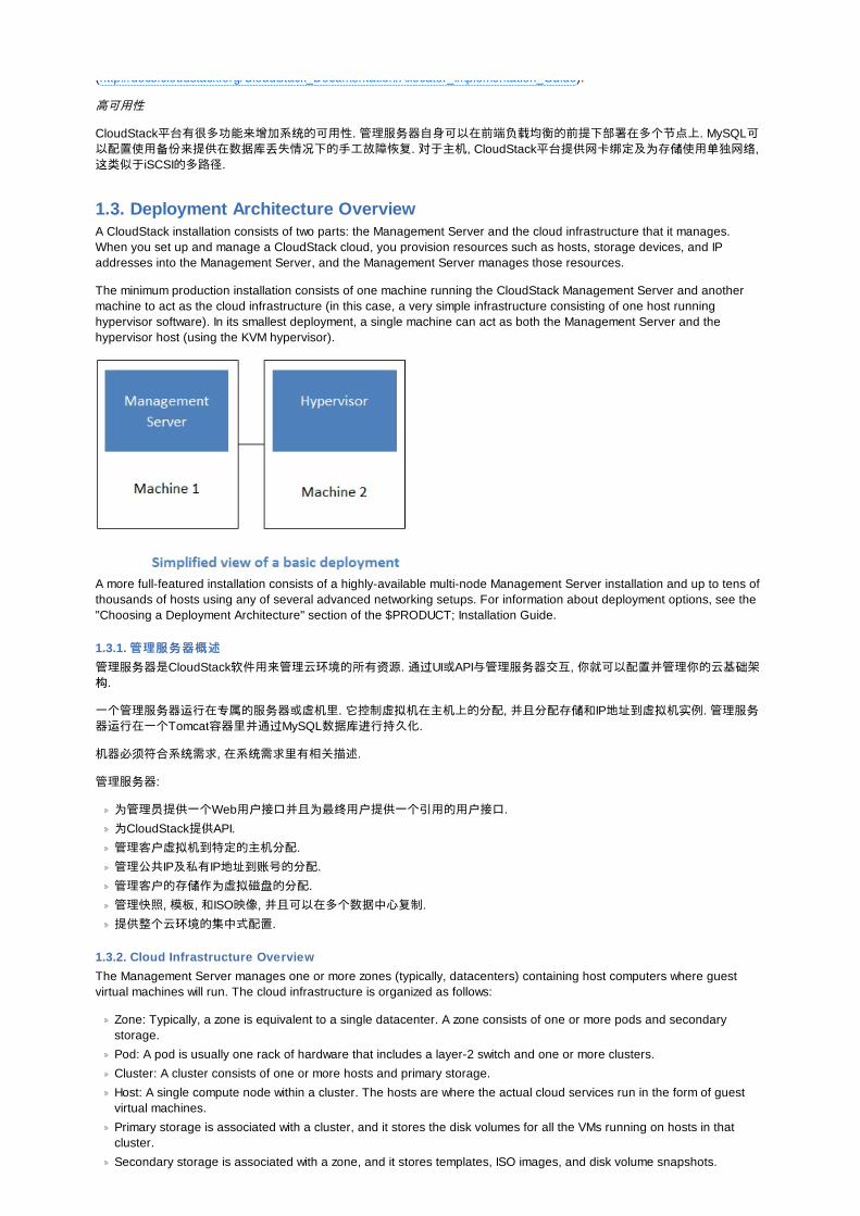
1.3. Deployment Architecture OverviewA CloudStack installation consists of two parts: the Management Server and the cloud infrastructure that it manages.When you set up and manage a CloudStack cloud, you provision resources such as hosts, storage devices, and IPaddresses into the Management Server, and the Management Server manages those resources.
The minimum production installation consists of one machine running the CloudStack Management Server and anothermachine to act as the cloud infrastructure (in this case, a very simple infrastructure consisting of one host runninghypervisor software). In its smallest deployment, a single machine can act as both the Management Server and thehypervisor host (using the KVM hypervisor).
A more full-featured installation consists of a highly-available multi-node Management Server installation and up to tens ofthousands of hosts using any of several advanced networking setups. For information about deployment options, see the"Choosing a Deployment Architecture" section of the $PRODUCT; Installation Guide.
1.3.1. 管理服管理服务务器概述器概述
管理服务器是CloudStack软件用来管理云环境的所有资源. 通过UI或API与管理服务器交互, 你就可以配置并管理你的云基础架构.
一个管理服务器运行在专属的服务器或虚机里. 它控制虚拟机在主机上的分配, 并且分配存储和IP地址到虚拟机实例. 管理服务器运行在一个Tomcat容器里并通过MySQL数据库进行持久化.
机器必须符合系统需求, 在系统需求里有相关描述.
管理服务器:
为管理员提供一个Web用户接口并且为最终用户提供一个引用的用户接口.
为CloudStack提供API.
管理客户虚拟机到特定的主机分配.
管理公共IP及私有IP地址到账号的分配.
管理客户的存储作为虚拟磁盘的分配.
管理快照, 模板, 和ISO映像, 并且可以在多个数据中心复制.
提供整个云环境的集中式配置.
1.3.2. Cloud Infrastructure OverviewThe Management Server manages one or more zones (typically, datacenters) containing host computers where guestvirtual machines will run. The cloud infrastructure is organized as follows:
Zone: Typically, a zone is equivalent to a single datacenter. A zone consists of one or more pods and secondarystorage.
Pod: A pod is usually one rack of hardware that includes a layer-2 switch and one or more clusters.
Cluster: A cluster consists of one or more hosts and primary storage.
Host: A single compute node within a cluster. The hosts are where the actual cloud services run in the form of guestvirtual machines.
Primary storage is associated with a cluster, and it stores the disk volumes for all the VMs running on hosts in thatcluster.
Secondary storage is associated with a zone, and it stores templates, ISO images, and disk volume snapshots.

More Information
For more information, see documentation on cloud infrastructure concepts.
1.3.3. 网网络络概述概述CloudStack提供两种类型的网络应用场景:
基本网络. 类似于AWS类型的网络. 提供一个单一网络, 在这个网络里客户通过提供的三层方式进行隔离,比如借安全组方式(源IP地址过滤).
高级网络. 为更复杂的网络拓扑设计. 网络模型提供了更为灵活的客户网络定义.
更详细的信息, 请参数网络设置.
第第 2 章章 云基云基础设础设施概念施概念
2.1. About RegionsTo increase reliability of the cloud, you can optionally group resources into multiple geographic regions. A region is thelargest available organizational unit within a CloudStack deployment. A region is made up of several availability zones,where each zone is roughly equivalent to a datacenter. Each region is controlled by its own cluster of ManagementServers, running in one of the zones. The zones in a region are typically located in close geographical proximity. Regionsare a useful technique for providing fault tolerance and disaster recovery.
By grouping zones into regions, the cloud can achieve higher availability and scalability. User accounts can span regions,so that users can deploy VMs in multiple, widely-dispersed regions. Even if one of the regions becomes unavailable, theservices are still available to the end-user through VMs deployed in another region. And by grouping communities ofzones under their own nearby Management Servers, the latency of communications within the cloud is reduced comparedto managing widely-dispersed zones from a single central Management Server.
Usage records can also be consolidated and tracked at the region level, creating reports or invoices for each geographicregion.
Regions are visible to the end user. When a user starts a guest VM, the user must select a region for their guest. Usersmight also be required to copy their private templates to additional regions to enable creation of guest VMs using theirtemplates in those regions.
2.2. 关于关于资资源域源域A zone is the second largest organizational unit within a CloudStack deployment. A zone typically corresponds to a singledatacenter, although it is permissible to have multiple zones in a datacenter. The benefit of organizing infrastructure intozones is to provide physical isolation and redundancy. For example, each zone can have its own power supply andnetwork uplink, and the zones can be widely separated geographically (though this is not required).
一个资源域包括:
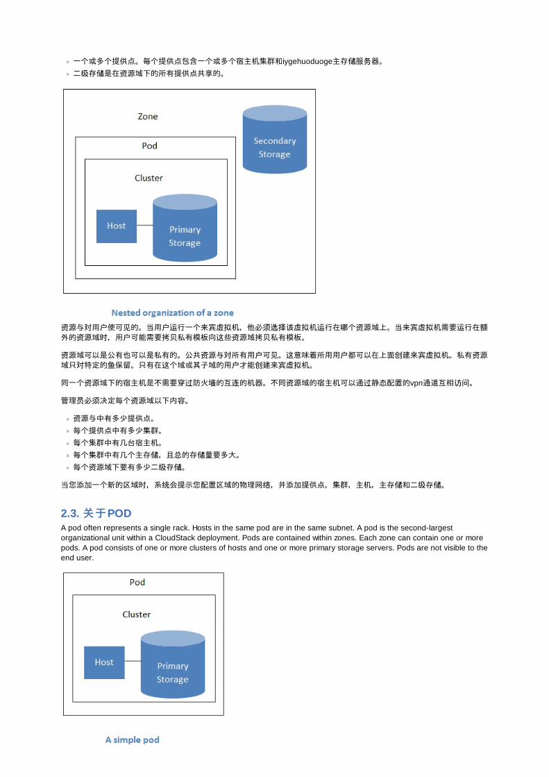
一个或多个提供点。每个提供点包含一个或多个宿主机集群和iygehuoduoge主存储服务器。二级存储是在资源域下的所有提供点共享的。
资源与对用户使可见的。当用户运行一个来宾虚拟机,他必须选择该虚拟机运行在哪个资源域上。当来宾虚拟机需要运行在额外的资源域时,用户可能需要拷贝私有模板向这些资源域拷贝私有模板。
资源域可以是公有也可以是私有的。公共资源与对所有用户可见。这意味着所用用户都可以在上面创建来宾虚拟机。私有资源域只对特定的鱼保留。只有在这个域或其子域的用户才能创建来宾虚拟机。
同一个资源域下的宿主机是不需要穿过防火墙的互连的机器。不同资源域的宿主机可以通过静态配置的vpn通道互相访问。
管理员必须决定每个资源域以下内容。
资源与中有多少提供点。每个提供点中有多少集群。
每个集群中有几台宿主机。
每个集群中有几个主存储,且总的存储量要多大。每个资源域下要有多少二级存储。
当您添加一个新的区域时,系统会提示您配置区域的物理网络,并添加提供点,集群,主机,主存储和二级存储。
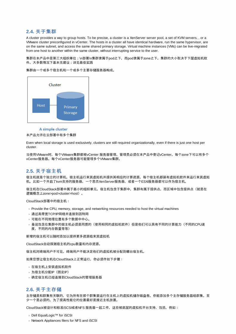
2.3. 关于关于PODA pod often represents a single rack. Hosts in the same pod are in the same subnet. A pod is the second-largestorganizational unit within a CloudStack deployment. Pods are contained within zones. Each zone can contain one or morepods. A pod consists of one or more clusters of hosts and one or more primary storage servers. Pods are not visible to theend user.
2.4. 关于集群关于集群A cluster provides a way to group hosts. To be precise, a cluster is a XenServer server pool, a set of KVM servers, , or aVMware cluster preconfigured in vCenter. The hosts in a cluster all have identical hardware, run the same hypervisor, areon the same subnet, and access the same shared primary storage. Virtual machine instances (VMs) can be live-migratedfrom one host to another within the same cluster, without interrupting service to the user.
集群在本产品中是第三大组织单位;\n部署\n集群隶属于pod之下,而pod隶属于zone之下。集群的大小取决于下层虚拟机软件。大多数情况下基本无建议;详见最佳实践
集群由一个或多个宿主机和一个或多个主要存储服务器构成。
本产品允许在云部署中有多个集群
Even when local storage is used exclusively, clusters are still required organizationally, even if there is just one host percluster.
当使用VMware时,每个VMware集群都被vCenter 服务器管理。管理员必须在本产品中登记vCenter。每个zone下可以有多个vCenter服务器。每个vCenter服务器可能管理多个VMware集群。
2.5. 关于宿主机关于宿主机宿主机就是个独立的计算机。宿主机运行来宾虚拟机并提供其相应的计算资源。每个宿主机都装有虚拟机软件来运行来宾虚拟机。比如一个开启了kvm支持的服务器,一个思杰XenServer服务器,或者一个ESXi服务器都可以作为宿主机。
宿主机在CloudStack部署中属于最小的组织单元。宿主机包含于集群中,集群有属于提供点,而区域中包含提供点(就是在逻辑概念上zone>pod>cluster>host)。
CloudStack部署中的宿主机:
Provide the CPU, memory, storage, and networking resources needed to host the virtual machines
通过高带宽TCP/IP网络并连接到因特网可能在不同地理位置有多个数据中中心。
虽说包含在集群中的宿主机必须是同质的(使用相同的虚拟机软件)但是他们可以具有不同的计算能力(不同的CPU速度,不同的内存数量等等)
新增的宿主机可以随时添加以提供更多资源给来宾虚拟机
CloudStack自动探测宿主机的cpu数量和内存资源。
宿主机对终端用户不可见。终端用户不能决定他们的虚拟机被分配到哪台宿主机。
如果您想让宿主机在CloudStack上正常运行,你必须作如下步骤:
在宿主机上安装虚拟机软件为宿主机分配IP(固定IP)
确定宿主机已经连接到CloudStack的管理服务器
2.6. 关于主存关于主存储储主存储是和群集有关联的,它为所有在那个群集里运行在主机上的虚拟机储存磁盘卷。你能添加多个主存储服务器给群集。至少一个是必须的。为了提高性能它的位置最好是接近主机放置。
CloudStack被设计和标准iSCSI或者NFS 服务器一起工作,这些被底层的虚拟机平台支持,包括,例如:
Dell EqualLogic™ for iSCSI
Network Appliances filers for NFS and iSCSI
Scale Computing for NFS
如果你打算使用本地磁盘当你安装的时候,你可以跳过去安装辅助存储。
2.7. 关与关与辅辅助存助存储储辅助存储是和区域关联,它存储如下事物:
模板— 操作系统镜像能够用来启动虚拟机并且可一包含额外配置信息,例如被按装的应用程序。ISO 镜像—磁盘镜像包含数据或者操作系统引导媒体。磁盘卷快照—被保存的虚拟机数据复制品能够被用来做数据恢复或者建立新的模板。
这些在基于区域的NFS辅助存储中的数据是对所有在这个区域内的主机有效的。
为了让这些在辅助存储中的数据对所有在云中的主机有效,你可以另外添加OpenStack对象存储(Swift,swift.openstack.org) 给基于区域的NFS辅助存储。当使用Swift时,你配置Swift存储给整个CloudStack,然后照常设置NFS 辅助存储给每个区域。在每个区域的NFS存储扮演了一个代转区,所有的模板和其他辅助存储的数据在转向Swift前将通过它。Swift 存储扮演了一个广泛云的资源,使得模板和其它数据是有效的对任何在云中的区域。Swift 存储中没有分级,每个存储对象只有一个Swift容器。任何在整个云中的辅助存储能够拖一个容器从Swift中在需要的时候。这样就不用拷贝模板和快照从一个区域到另外一个区域了,如果单独使用区域NFS的话,还是需要的。任何事情都是有效的在任何地方。
2.8. 关于物理网关于物理网络络设置物理网络是添加区域步骤中的一个部分。每个区域可以分配一个(极限与高级资源域)或者多个物理网络。这个网络对应宿主机的一个网卡。每个物理网络可以承载一种或多种网络流量。每个网络流量的类型的选项由你选择的是基本网络与还是高级网络与而不同。
物理网络是连接到资源与的真实网络硬件。一个资源与能有多个物理网络。管理员能做一下操作:
添加/删除/更新 域中的物理网络在物理网络上设置VLAN
通过设置名字使网络能被虚拟机软件识别设置在物理网络上能够提供的服务(防火墙,负载均衡器,等等)设置能直连到物理网络的IP地址
指定物理网络承载的流量类型还有其他类似网络速度之类的属性
2.8.1. 基本区域网基本区域网络络流量流量类类型型当使用基本网络是,这里只有一个物理网卡在区域中。这个物理网卡承载以下类型流量:
来宾。当终端用户运行虚拟,他们产生来宾流量。来宾虚拟机和其他虚拟机通信在网络上的流量,归功来宾网络。每一个pod中的基本区域就是一个广播域,因此每个一个pod中的来宾网络拥有不同的ip范围。管理员必须为每一个pod配置ip范围。管理。当 CloudStack最为内部资源和其他通信时,他们产生管理流量。包括主机,系统vm(在云中,被用于CloudStack执行大量任务的虚拟机)之间的通信, 其他组件和CloudStack 管理服务器的直接通信。你必须为系统vm配置一个ip范围。
注意注意
我们强烈要求管理和来宾流量使用独立的网卡
公共。云中的虚拟机访问internet时产生公共流量,基于这个原因必须分配可供访问的ip地址。终端用户可以使用CloudStack UI获得一个ip,用来构建来宾网络和公共网络的nat。定义为:获取新的ip地址。
存储。存储流量是vm模板,快照在辅助存储vm和辅助存储服务器之间发送的流量。CloudStack使用一个叫做存储nic的独立网络接口控制器(NIC)提供给存储网络流。storage nic 功能在于为模板和快照的快速复制提供很高的带宽网络。你必须为存储网络配置ip范围
在基本区域中,配置物理网络是相当简单的。在大多数情况下,你只需要配置一个来宾网络承载所有来宾虚拟机流量。如果你使用NetScaler负载平衡器,开启弹性的IP和弹性负载平衡(EIP和ELB)的功能,你还必须配置一个网络承载公共流量。 当你通过UI添加一个新的区域, CloudStack负责提出必要的网络配置的步骤。
2.8.2. 基本区域基本区域宾宾客客 IP 地址地址当基本联网方式被使用, CloudStack 将在POD CIDR的IP 地址分配给该POD中的宾客。 管理员必须在此POD增加一个直接IP 范围用于此目的。 这些IP 和主机位于同样的VLAN。
2.8.3. 高高级级区域网区域网络络流量流量类类型型当使用高级网路时,在区域包含多种物理网络。每一个物理网络能够承载一种或者多种类型的流量。要让 CloudStack 知道每种网络承载那种类型的流量。高级区域包含的流量类型:
来宾。当用户允许VM时,他们产生来宾流量。来宾VM通过来宾网络进相关通讯。这个网络可以是隔离或者共享的;在隔
来宾。当用户允许VM时,他们产生来宾流量。来宾VM通过来宾网络进相关通讯。这个网络可以是隔离或者共享的;在隔离的来宾网络中,管理员需要为每一个 CloudStack 中隔离网络分配 VLAN 范围;帐户的网络(潜在的大量的VLAN)。在一个共享来宾网络中,所有来宾VM共享一个网络。管理。当 CloudStack最为内部资源和其他通信时,他们产生管理流量。包括主机,系统vm(在云中,被用于CloudStack执行大量任务的虚拟机)之间的通信, 其他组件和CloudStack 管理服务器的直接通信。你必须为系统vm配置一个ip范围。Public. Public traffic is generated when VMs in the cloud access the Internet. Publicly accessible IPs must be allocatedfor this purpose. End users can use the CloudStack UI to acquire these IPs to implement NAT between their guestnetwork and the public network, as described in “Acquiring a New IP Address” in the Administration Guide.
存储。存储流量是vm模板,快照在辅助存储vm和辅助存储服务器之间发送的流量。CloudStack使用一个叫做存储nic的独立网络接口控制器(NIC)提供给存储网络流。storage nic 功能在于为模板和快照的快速复制提供很高的带宽网络。你必须为存储网络配置ip范围
These traffic types can each be on a separate physical network, or they can be combined with certain restrictions. Whenyou use the Add Zone wizard in the UI to create a new zone, you are guided into making only valid choices.
2.8.4. 高高级级区域区域宾宾客的客的 IP地址地址使用高级的网络时,管理员可以创建额外的网络供客人使用。这些网络可以跨越区域,并提供给所有帐户,或者他们可以到一个单一的帐户范围内,在这种情况下,只有指定的帐户可以创建连接到这些网络的宾客。网络被定义为一个VLAN ID,IP范围和网关。如果需要的话,系统管理员可能会提供成千上万的网络。
2.8.5. Advanced Zone Public IP Addresses使用高级的网络时,管理员可以创建额外的网络供客人使用。这些网络可以跨越区域,并提供给所有帐户,或者他们可以到一个单一的帐户范围内,在这种情况下,只有指定的帐户可以创建连接到这些网络的宾客。网络被定义为一个VLAN ID,IP范围和网关。如果需要的话,系统管理员可能会提供成千上万的网络。
2.8.6. System Reserved IP AddressesIn each zone, you need to configure a range of reserved IP addresses for the management network. This network carriescommunication between the CloudStack Management Server and various system VMs, such as Secondary Storage VMs,Console Proxy VMs, and DHCP.
The reserved IP addresses must be unique across the cloud. You cannot, for example, have a host in one zone which hasthe same private IP address as a host in another zone.
The hosts in a pod are assigned private IP addresses. These are typically RFC1918 addresses. The Console Proxy andSecondary Storage system VMs are also allocated private IP addresses in the CIDR of the pod that they are created in.
Make sure computing servers and Management Servers use IP addresses outside of the System Reserved IP range. Forexample, suppose the System Reserved IP range starts at 192.168.154.2 and ends at 192.168.154.7. CloudStack can use.2 to .7 for System VMs. This leaves the rest of the pod CIDR, from .8 to .254, for the Management Server and hypervisorhosts.
In all zones:
Provide private IPs for the system in each pod and provision them in CloudStack.
For KVM and XenServer, the recommended number of private IPs per pod is one per host. If you expect a pod to grow,add enough private IPs now to accommodate the growth.
In a zone that uses advanced networking:
For zones with advanced networking, we recommend provisioning enough private IPs for your total number of customers,plus enough for the required CloudStack System VMs. Typically, about 10 additional IPs are required for the System VMs.For more information about System VMs, see Working with System Virtual Machines in the Administrator's Guide.
When advanced networking is being used, the number of private IP addresses available in each pod varies depending onwhich hypervisor is running on the nodes in that pod. Citrix XenServer and KVM use link-local addresses, which in theoryprovide more than 65,000 private IP addresses within the address block. As the pod grows over time, this should be morethan enough for any reasonable number of hosts as well as IP addresses for guest virtual routers. VMWare ESXi, bycontrast uses any administrator-specified subnetting scheme, and the typical administrator provides only 255 IPs per pod.Since these are shared by physical machines, the guest virtual router, and other entities, it is possible to run out of privateIPs when scaling up a pod whose nodes are running ESXi.
To ensure adequate headroom to scale private IP space in an ESXi pod that uses advanced networking, use one or bothof the following techniques:
Specify a larger CIDR block for the subnet. A subnet mask with a /20 suffix will provide more than 4,000 IP addresses.
Create multiple pods, each with its own subnet. For example, if you create 10 pods and each pod has 255 IPs, this willprovide 2,550 IP addresses.
第第 3 章章 Building from SourceThe official CloudStack release is always in source code form. You will likely be able to find "convenience binaries," the
The official CloudStack release is always in source code form. You will likely be able to find "convenience binaries," thesource is the canonical release. In this section, we'll cover acquiring the source release and building that so that you candeploy it using Maven or create Debian packages or RPMs.
Note that building and deploying directly from source is typically not the most efficient way to deploy an IaaS. However, wewill cover that method as well as building RPMs or Debian packages for deploying CloudStack.
The instructions here are likely version-specific. That is, the method for building from source for the 4.0.x series is differentfrom the 4.1.x series.
If you are working with a unreleased version of CloudStack, see the INSTALL.md file in the top-level directory of therelease.
3.1. 获获得得发发行版行版你可以从 Apache CloudStack project download page下载最新的CloudStack
Prior releases are available via archive.apache.org at http://archive.apache.org/dist/incubator/cloudstack/releases/.
You'll notice several links under the 'Latest release' section. A link to a file ending in tar.bz2, as well as a PGP/GPGsignature, MD5, and SHA512 file.
The tar.bz2 file contains the Bzip2-compressed tarball with the source code.
The .asc file is a detached cryptographic signature that can be used to help verify the authenticity of the release.
The .md5 file is an MD5 hash of the release to aid in verify the validity of the release download.
The .sha file is a SHA512 hash of the release to aid in verify the validity of the release download.
3.2. Verifying the downloaded releaseThere are a number of mechanisms to check the authenticity and validity of a downloaded release.
3.2.1. Getting the KEYSTo enable you to verify the GPG signature, you will need to download the KEYS file.
You next need to import those keys, which you can do by running:
# gpg --import KEYS
3.2.2. GPGThe CloudStack project provides a detached GPG signature of the release. To check the signature, run the followingcommand:
$ gpg --verify apache-cloudstack-4.0.0-incubating-src.tar.bz2.asc
If the signature is valid you will see a line of output that contains 'Good signature'.
3.2.3. MD5In addition to the cryptographic signature, CloudStack has an MD5 checksum that you can use to verify the downloadmatches the release. You can verify this hash by executing the following command:
$ gpg --print-md MD5 apache-cloudstack-4.0.0-incubating-src.tar.bz2 | diff - apache-cloudstack-4.0.0-incubating-src.tar.bz2.md5
If this successfully completes you should see no output. If there is any output from them, then there is a differencebetween the hash you generated locally and the hash that has been pulled from the server.
3.2.4. SHA512In addition to the MD5 hash, the CloudStack project provides a SHA512 cryptographic hash to aid in assurance of thevalidity of the downloaded release. You can verify this hash by executing the following command:
$ gpg --print-md SHA512 apache-cloudstack-4.0.0-incubating-src.tar.bz2 | diff - apache-cloudstack-4.0.0-incubating-src.tar.bz2.sha
If this command successfully completes you should see no output. If there is any output from them, then there is adifference between the hash you generated locally and the hash that has been pulled from the server.
3.3. Prerequisites for building Apache CloudStackThere are a number of prerequisites needed to build CloudStack. This document assumes compilation on a Linux system
There are a number of prerequisites needed to build CloudStack. This document assumes compilation on a Linux systemthat uses RPMs or DEBs for package management.
You will need, at a minimum, the following to compile CloudStack:
1. Maven (version 3)
2. Java (OpenJDK 1.6 or Java 7/OpenJDK 1.7)
3. Apache Web Services Common Utilities (ws-commons-util)
4. MySQL
5. MySQLdb (provides Python database API)
6. Tomcat 6 (not 6.0.35)
7. genisoimage
8. rpmbuild or dpkg-dev
3.4. Extracting sourceExtracting the CloudStack release is relatively simple and can be done with a single command as follows:
$ tar -jxvf apache-cloudstack-4.0.0-incubating-src.tar.bz2
You can now move into the directory:
$ cd ./apache-cloudstack-4.0.0-incubating-src
3.5. 编译编译DEB包包除了启动的依赖包, 你还需要安装其它的几个依赖. 请注意我们推荐使用Maven 3, 在目前12.04.1 LTS里不可用. 所以你需要添加个人的软件仓库来包含Maven 3. 在运行完add-apt-repository后, 将提示你继续并且一个GPG key将会被添加.
$ sudo apt-get update$ sudo apt-get install python-software-properties$ sudo add-apt-repository ppa:natecarlson/maven3$ sudo apt-get update$ sudo apt-get install ant debhelper openjdk-6-jdk tomcat6 libws-commons-util-java genisoimage python-mysqldb libcommons-codec-java libcommons-httpclient-java liblog4j1.2-java maven3
While we have defined, and you have presumably already installed the bootstrap prerequisites, there are a number ofbuild time prerequisites that need to be resolved. CloudStack uses maven for dependency resolution. You can resolve thebuildtime depdencies for CloudStack by running:
$ mvn3 -P deps
Now that we have resolved the dependencies we can move on to building CloudStack and packaging them into DEBs byissuing the following command.
$ dpkg-buildpackge -uc -us
This command will build 16 Debian packages. You should have all of the following:
cloud-agent_4.0.0-incubating_amd64.debcloud-agent-deps_4.0.0-incubating_amd64.debcloud-agent-libs_4.0.0-incubating_amd64.debcloud-awsapi_4.0.0-incubating_amd64.debcloud-cli_4.0.0-incubating_amd64.debcloud-client_4.0.0-incubating_amd64.debcloud-client-ui_4.0.0-incubating_amd64.debcloud-core_4.0.0-incubating_amd64.debcloud-deps_4.0.0-incubating_amd64.debcloud-python_4.0.0-incubating_amd64.debcloud-scripts_4.0.0-incubating_amd64.debcloud-server_4.0.0-incubating_amd64.debcloud-setup_4.0.0-incubating_amd64.debcloud-system-iso_4.0.0-incubating_amd64.debcloud-usage_4.0.0-incubating_amd64.debcloud-utils_4.0.0-incubating_amd64.deb
3.5.1. Setting up an APT repoAfter you've created the packages, you'll want to copy them to a system where you can serve the packages over HTTP.You'll create a directory for the packages and then use dpkg-scanpackages to create Packages.gz, which holdsinformation about the archive structure. Finally, you'll add the repository to your system(s) so you can install the packages
information about the archive structure. Finally, you'll add the repository to your system(s) so you can install the packagesusing APT.
The first step is to make sure that you have the dpkg-dev package installed. This should have been installed when youpulled in the debhelper application previously, but if you're generating Packages.gz on a different system, be sure thatit's installed there as well.
$ sudo apt-get install dpkg-dev
The next step is to copy the DEBs to the directory where they can be served over HTTP. We'll use /var/www/cloudstack/repo in the examples, but change the directory to whatever works for you.
sudo mkdir -p /var/www/cloudstack/repo/binarysudo cp *.deb /var/www/cloudstack/repo/binarysudo cd /var/www/cloudstack/repo/binarysudo dpkg-scanpackages . /dev/null | tee Packages | gzip -9 > Packages.gz
Note: Override Files
You can safely ignore the warning about a missing override file.
Now you should have all of the DEB packages and Packages.gz in the binary directory and available over HTTP. (Youmay want to use wget or curl to test this before moving on to the next step.)
3.5.2. Configuring your machines to use the APT repositoryNow that we have created the repository, you need to configure your machine to make use of the APT repository. You cando this by adding a repository file under /etc/apt/sources.list.d. Use your preferred editor to create /etc/apt/sources.list.d/cloudstack.list with this line:
deb http://server.url/cloudstack/repo binary ./
Now that you have the repository info in place, you'll want to run another update so that APT knows where to find theCloudStack packages.
$ sudo apt-get update
You can now move on to the instructions under Install on Ubuntu.
3.6. Building RPMs from SourceAs mentioned previously in 第 3.3 节 “Prerequisites for building Apache CloudStack”, you will need to install severalprerequisites before you can build packages for CloudStack. Here we'll assume you're working with a 64-bit build ofCentOS or Red Hat Enterprise Linux.
# yum groupinstall "Development Tools"
# yum install java-1.6.0-openjdk-devel.x86_64 genisoimage mysql mysql-server ws-common-utils MySQL-python tomcat6 createrepo
Next, you'll need to install build-time dependencies for CloudStack with Maven. We're using Maven 3, so you'll want to graba Maven 3 tarball and uncompress it in your home directory (or whatever location you prefer):
$ tar zxvf apache-maven-3.0.4-bin.tar.gz
$ export PATH=/usr/local/apache-maven-3.0.4//bin:$PATH
Maven also needs to know where Java is, and expects the JAVA_HOME environment variable to be set:
$ export JAVA_HOME=/usr/lib/jvm/jre-1.6.0-openjdk.x86_64/
Verify that Maven is installed correctly:
$ mvn --version
You probably want to ensure that your environment variables will survive a logout/reboot. Be sure to update ~/.bashrcwith the PATH and JAVA_HOME variables.
Building RPMs for $PRODUCT; is fairly simple. Assuming you already have the source downloaded and have
Building RPMs for $PRODUCT; is fairly simple. Assuming you already have the source downloaded and haveuncompressed the tarball into a local directory, you're going to be able to generate packages in just a few minutes.
Packaging has Changed
If you've created packages for $PRODUCT; previously, you should be aware that the process has changedconsiderably since the project has moved to using Apache Maven. Please be sure to follow the steps in this sectionclosely.
3.6.1. Generating RPMSNow that we have the prerequisites and source, you will cd to the packaging/centos63/ directory.
Generating RPMs is done using the package.sh script:
$ ./package.sh
That will run for a bit and then place the finished packages in dist/rpmbuild/RPMS/x86_64/.
You should see seven RPMs in that directory: cloudstack-agent-4.1.0-SNAPSHOT.el6.x86_64.rpm, cloudstack-awsapi-4.1.0-SNAPSHOT.el6.x86_64.rpm, cloudstack-cli-4.1.0-SNAPSHOT.el6.x86_64.rpm, cloudstack-common-4.1.0-SNAPSHOT.el6.x86_64.rpm, cloudstack-docs-4.1.0-SNAPSHOT.el6.x86_64.rpm, cloudstack-management-4.1.0-SNAPSHOT.el6.x86_64.rpm, and cloudstack-usage-4.1.0-SNAPSHOT.el6.x86_64.rpm.
3.6.1.1. 创创建一个建一个yum 库库While RPMs is a useful packaging format - it's most easily consumed from Yum repositories over a network. The next stepis to create a Yum Repo with the finished packages:
$ mkdir -p ~/tmp/repo
$ cp dist/rpmbuild/RPMS/x86_64/*rpm ~/tmp/repo/
$ createrepo ~/tmp/repo
The files and directories within ~/tmp/repo can now be uploaded to a web server and serve as a yum repository.
3.6.1.2. 配置你的系配置你的系统统使用新的使用新的yum源源Now that your yum repository is populated with RPMs and metadata we need to configure the machines that need to install$PRODUCT;. Create a file named /etc/yum.repos.d/cloudstack.repo with this information:
[apache-cloudstack] name=Apache CloudStack baseurl=http://webserver.tld/path/to/repo enabled=1 gpgcheck=0
Completing this step will allow you to easily install $PRODUCT; on a number of machines across the network.
第第 4 章章 安装安装
4.1. 谁应该阅读谁应该阅读本文本文For those who have already gone through a design phase and planned a more sophisticated deployment, or those whoare ready to start scaling up a trial installation. With the following procedures, you can start using the more powerfulfeatures of CloudStack, such as advanced VLAN networking, high availability, additional network elements such as loadbalancers and firewalls, and support for multiple hypervisors including Citrix XenServer, KVM, and VMware vSphere.
4.2. Overview of Installation StepsFor anything more than a simple trial installation, you will need guidance for a variety of configuration choices. It is stronglyrecommended that you read the following:
选择一个部署体系结构Choosing a Hypervisor: Supported Features
网络配置Storage Setup
Best Practices
Best Practices
1. Make sure you have the required hardware ready. See 第 4.3 节 “最小化系统需求”
2. Install the Management Server (choose single-node or multi-node). See 第 4.5 节 “管理服务器安装”
3. Log in to the UI. See 第 5 章 用户界面4. Add a zone. Includes the first pod, cluster, and host. See 第 6.3 节 “创建Zone”
5. Add more pods (optional). See 第 6.4 节 “添加一个机架”
6. Add more clusters (optional). See 第 6.5 节 “添加集群”
7. Add more hosts (optional). See 第 6.6 节 “Adding a Host”
8. Add more primary storage (optional). See 第 6.7 节 “æ·»å 主å å ¨”9. Add more secondary storage (optional). See 第 6.8 节 “æ·»å è¾ å ©å å ¨”
10. Try using the cloud. See 第 6.9 节 “初始化和测试”
4.3. 最小化系最小化系统统需求需求
4.3.1. 系系统统管理服管理服务务器,数据器,数据库库和存和存储储系系统统需求需求运行管理服务器和mysql数据库的机器必须满足以下要求。同样的机器也可以用来提供主要存储和二级存储,碧土通过本地磁盘和NFS。管理服务器可以安装在虚拟机中。
操作系统:Preferred: CentOS/RHEL 6.3+ or Ubuntu 12.04(.1)
64位x86架构CPU(多个核心性能更好)
4GB内存
250GB本地硬盘 (更大的容量性能更佳;推荐500GB)
至少一块网卡静态分配的IP地址
通过hostname命令返回的完全合格的域名
4.3.2. 宿主机宿主机 /虚虚拟拟机机软软件系件系统统需求需求宿主机以虚拟机形式提供云服务。每个宿主机需满足以下要求。
Must support HVM (Intel-VT or AMD-V enabled).
64位x86架构CPU(多个核心性能更好)
需求硬件虚拟化支持4GB内存
36GB的本地磁盘至少一块网卡
注意注意
If DHCP is used for hosts, ensure that no conflict occurs between DHCP server used for these hosts and theDHCP router created by CloudStack.
虚拟机软件已打好了最新补丁部署CloudStack时宿主机务必不能有任何运行中的虚拟机。All hosts within a cluster must be homogenous. The CPUs must be of the same type, count, and feature flags.
宿主机的其余需求取决于所使用的虚拟机软件。详情查看你所采用的虚拟机软件的安装区域列出的需求。
警告警告
如果你按照本指南的步骤并确定你满足了所选用虚拟机软件的 要求。宿主机应该就可以在Cloudstack中正常工作了。比如XenServer的要求就列在思杰XenServer安装部分。
第 8.1.1 节 “System Requirements for KVM Hypervisor Hosts”
第 8.2.1 节 “XenServer主机的系统要求”
第 8.3.1 节 “System Requirements for vSphere Hosts”
4.4. Configure package repository
4.4. Configure package repositoryCloudStack is only distributed from source from the official mirrors. However, members of the CloudStack community maybuild convenience binaries so that users can install Apache CloudStack without needing to build from source.
If you didn't follow the steps to build your own packages from source in the sections for 第 3.6 节 “Building RPMs fromSource” or 第 3.5 节 “编译DEB包” you may find pre-built DEB and RPM packages for your convience linked from thedownloads page.
注意注意
These repositories contain both the Management Server and KVM Hypervisor packages.
4.4.1. DEB package repositoryYou can add a DEB package repository to your apt sources with the following commands. Please note that only packagesfor Ubuntu 12.04 LTS (precise) are being built at this time.
Use your preferred editor and open (or create) /etc/apt/sources.list.d/cloudstack.list. Add the communityprovided repository to the file:
deb http://cloudstack.apt-get.eu/ubuntu precise 4.0
We now have to add the public key to the trusted keys.
$ wget -O - http://cloudstack.apt-get.eu/release.asc|apt-key add -
Now update your local apt cache.
$ apt-get update
Your DEB package repository should now be configured and ready for use.
4.4.2. RPM package repositoryThere is a RPM package repository for CloudStack so you can easily install on RHEL based platforms.
If you're using an RPM-based system, you'll want to add the Yum repository so that you can install CloudStack with Yum.
Yum repository information is found under /etc/yum.repos.d. You'll see several .repo files in this directory, each onedenoting a specific repository.
To add the CloudStack repository, create /etc/yum.repos.d/cloudstack.repo and insert the following information.
[cloudstack]name=cloudstackbaseurl=http://cloudstack.apt-get.eu/rhel/4.0/enabled=1gpgcheck=0
Now you should be able to install CloudStack using Yum.
4.5. 管理服管理服务务器安装器安装
4.5.1. 管理服管理服务务器安装概述器安装概述
本章节介绍管理服务器的安装. 根据你云环境中管理服务器节点个数的不同, 安装步骤有两处稍有不同.
一个单独的管理服务器节点, MySQL也装在这个节点上.
多个管理服务器节点, MySQL装在与所有管理服务都不相同的节点上.
不管是哪种方案, 所有系统的要求都会符合系统需求里的描述.
警告警告
为安全起见, 确保公共网络不能访问管理服务器的8096和8250端口.
安装管理服务器的步骤:
1. 准备操作系统
2. (XenServer only) Download and install vhd-util.
3. 安装第一台管理服务器4. 安装并配置MySQL数据库5. 准备NFS共享存储6. 准备并启动额外的管理服务器(可选)
7. 准备系统虚拟机模板
4.5.2. 准准备备操作系操作系统统要在主机上安装管理服务器,需要按下列步骤准备操作系统. 这些步骤必须在每个要安装的管理服务器节点上执行.
1. 作为root用户登入你的系统.
2. 检查全称域名.
hostname --fqdn
这将会返回一个全称域名例如"managament1.lab.example.org". 如果不是这样, 请编辑/etc/hosts使其返回类似的结果.
3. 确保机器可以连接到互联网.
ping www.cloudstack.org
4. 启用NTP服务以确保时间同步.
注意注意
NTP对于你云环境中服务器时钟同步是必须的.
a. 安装NTP服务.
yum install ntp
apt-get install openntpd
5. 在每一个安装管理服务器的节点上重复所有这些步骤.
4.5.3. 在第一台主机上安装管理服在第一台主机上安装管理服务务器器安装的第一步,不论你在一台或多台主机上安装管理服务器,在一个单机上安装这些软件。
注意注意
如果你计划为了高可用在多个节点安装管理服务器,目前不要进行添加其他节点,这个会在后面的步骤中进行
CloudStack管理服务器可以用RMP或者DEB包来安装,这些包会依赖运行管理服务器的所有需要的东西。
4.5.3.1. 在在CentOS/RHEL上安装上安装
我们开始安装需要的软件包:
yum install cloud-client
4.5.3.2. 在在ubuntu上安装上安装
apt-get install cloud-client
4.5.3.3. Downloading vhd-utilThis procedure is required only for installations where XenServer is installed on the hypervisor hosts.
Before setting up the Management Server, download vhd-util from vhd-util.
If the Management Server is RHEL or CentOS, copy vhd-util to /usr/lib64/cloud/common/scripts/vm/hypervisor/xenserver.
If the Management Server is Ubuntu, copy vhd-util to /usr/lib/cloud/common/scripts/vm/hypervisor/xenserver.
4.5.4. 安装数据安装数据库库服服务务器器CloudStack 管理服务器使用MySQL 数据服务器存储数据。当你在一个单独的解决安装管理服务器,你可以在本地安装MySQL服务器。如果是安装多节点管理服务器,我们假设MySQL数据库也运行在一个单独的节点。
CloudStack 已经测试过MySQL5.1和5.5。这些版本包含在RHEL/CentOS and Ubuntu.
4.5.4.1. 在管理服在管理服务务器器节节点上安装数据点上安装数据库库This section describes how to install MySQL on the same machine with the Management Server. This technique isintended for a simple deployment that has a single Management Server node. If you have a multi-node ManagementServer deployment, you will typically use a separate node for MySQL. See 第 4.5.4.2 节 “在一个单独的节点上安装数据库。”.
1. Install MySQL from the package repository of your distribution:
yum install mysql-server
apt-get install mysql-server
2. Open the MySQL configuration file. The configuration file is /etc/my.cnf or /etc/mysql/my.cnf, depending onyour OS.
3. Insert the following lines in the [mysqld] section.
You can put these lines below the datadir line. The max_connections parameter should be set to 350 multiplied bythe number of Management Servers you are deploying. This example assumes one Management Server.
注意注意
On Ubuntu, you can also create a file /etc/mysql/conf.d/cloudstack.cnf and add these directivesthere. Don't forget to add [mysqld] on the first line of the file.
innodb_rollback_on_timeout=1innodb_lock_wait_timeout=600max_connections=350log-bin=mysql-binbinlog-format = 'ROW'
4. Start or restart MySQL to put the new configuration into effect.
On RHEL/CentOS, MySQL doesn't automatically start after installation. Start it manually.
service mysqld start
On Ubuntu, restart MySQL.
service mysqld restart
5. (CentOS and RHEL only; not required on Ubuntu)
警告警告
On RHEL and CentOS, MySQL does not set a root password by default. It is very strongly recommended thatyou set a root password as a security precaution.
Run the following command to secure your installation. You can answer "Y" to all questions.
mysql_secure_installation
6. CloudStack can be blocked by security mechanisms, such as SELinux. Disable SELinux to ensure + that the Agenthas all the required permissions.
Configure SELinux (RHEL and CentOS):
a. Check whether SELinux is installed on your machine. If not, you can skip this section.
In RHEL or CentOS, SELinux is installed and enabled by default. You can verify this with:
$ rpm -qa | grep selinux
b. Set the SELINUX variable in /etc/selinux/config to "permissive". This ensures that the permissive settingwill be maintained after a system reboot.
在RHEL 或 Centos:
vi /etc/selinux/config
Change the following line
SELINUX=enforcing
to this:
SELINUX=permissive
c. Set SELinux to permissive starting immediately, without requiring a system reboot.
$ setenforce permissive
7. Set up the database. The following command creates the "cloud" user on the database.
In dbpassword, specify the password to be assigned to the "cloud" user. You can choose to provide nopassword although that is not recommended.
In deploy-as, specify the username and password of the user deploying the database. In the following command,it is assumed the root user is deploying the database and creating the "cloud" user.
(Optional) For encryption_type, use file or web to indicate the technique used to pass in the databaseencryption password. Default: file. See 第 4.5.5 节 “About Password and Key Encryption”.
(Optional) For management_server_key, substitute the default key that is used to encrypt confidentialparameters in the CloudStack properties file. Default: password. It is highly recommended that you replace thiswith a more secure value. See 第 4.5.5 节 “About Password and Key Encryption”.
(Optional) For database_key, substitute the default key that is used to encrypt confidential parameters in theCloudStack database. Default: password. It is highly recommended that you replace this with a more securevalue. See 第 4.5.5 节 “About Password and Key Encryption”.
(Optional) For management_server_ip, you may explicitly specify cluster management server node IP. If notspecified, the local IP address will be used.
cloud-setup-databases cloud:<dbpassword>@localhost \--deploy-as=root:<password> \-e <encryption_type> \-m <management_server_key> \-k <database_key> \-i <management_server_ip>
当这个脚本完成后,你应该看到类似这样的信息: “Successfully initialized the database.”
8. If you are running the KVM hypervisor on the same machine with the Management Server, edit /etc/sudoers and addthe following line:
Defaults:cloud !requiretty
9. 现在数据库已经设置好, 你可以完成管理服务器的设置. 这个命令将会设置iptables, sudoers并运行管理服务器的服务.
# cloud-setup-management
You should see the message “CloudStack Management Server setup is done.”
4.5.4.2. 在一个在一个单单独的独的节节点上安装数据点上安装数据库库。。This section describes how to install MySQL on a standalone machine, separate from the Management Server. Thistechnique is intended for a deployment that includes several Management Server nodes. If you have a single-nodeManagement Server deployment, you will typically use the same node for MySQL. See 第 4.5.4.1 节 “在管理服务器节点上安装数据库”.
注意注意
The management server doesn't require a specific distribution for the MySQL node. You can use a distribution orOperating System of your choice. Using the same distribution as the management server is recommended, but notrequired. See 第 4.3.1 节 “系统管理服务器,数据库和存储系统需求”.
1. Install MySQL from the package repository from your distribution:
yum install mysql-server
apt-get install mysql-server
2. 编辑MySQL配置文件 (/etc/my.cnf 或者 /etc/mysql/my.cnf ,因用户的操作系统而异),将如下语句插入[mysqld]段落。用户可以把这些语句加到datadir行之下。第三行的参数max_connections parameter应该设为350乘以你部署的管理服务器的个数。本例中假定有2个管理服务器。
注意注意

注意注意
On Ubuntu, you can also create /etc/mysql/conf.d/cloudstack.cnf file and add these directives there. Don'tforget to add [mysqld] on the first line of the file.
innodb_rollback_on_timeout=1innodb_lock_wait_timeout=600max_connections=700log-bin=mysql-binbinlog-format = 'ROW'bind-address = 0.0.0.0
3. Start or restart MySQL to put the new configuration into effect.
On RHEL/CentOS, MySQL doesn't automatically start after installation. Start it manually.
service mysqld start
On Ubuntu, restart MySQL.
service mysqld restart
4. (CentOS and RHEL only; not required on Ubuntu)
警告警告
On RHEL and CentOS, MySQL does not set a root password by default. It is very strongly recommended thatyou set a root password as a security precaution.
Run the following command to secure your installation. You can answer "Y" to all questions except "Disallow rootlogin remotely?". Remote root login is required to set up the databases.
mysql_secure_installation
5. If a firewall is present on the system, open TCP port 3306 so external MySQL connections can be established.
On Ubuntu, UFW is the default firewall. Open the port with this command:
ufw allow mysql
On RHEL/CentOS:
a. 编辑文件 /etc/sysconfig/iptables并在INPUT链上添加下面一行.
-A INPUT -p tcp --dport 3306 -j ACCEPT
b. Now reload the iptables rules.
service iptables restart
6. Return to the root shell on your first Management Server.
7. 设置数据库. 下列的命令会在数据库中创建云环境的用户.
dbpassword, 指定云环境用户的密码. 你可以选择不提供密码.
deploy-as, 指定安装数据库的用户名和密码. 在下面的命令中, root用户部署了数据库并创建的云环境用户.
(Optional) For encryption_type, use file or web to indicate the technique used to pass in the databaseencryption password. Default: file. See 第 4.5.5 节 “About Password and Key Encryption”.
(可选)management_server_key, 在CloudStack中替代默认的Key来加密机密的参数. 默认是password. 这里强烈建议你使用你替换成一个更安全的密码. 可参考关于密码和加密章节.
(Optional) For database_key, substitute the default key that is used to encrypt confidential parameters in theCloudStack database. Default: password. It is highly recommended that you replace this with a more securevalue. See 第 4.5.5 节 “About Password and Key Encryption”.
(Optional) For management_server_ip, you may explicitly specify cluster management server node IP. If notspecified, the local IP address will be used.
cloud-setup-databases cloud:<dbpassword>@<ip address mysql server> \--deploy-as=root:<password> \-e <encryption_type> \-m <management_server_key> \-k <database_key> \-i <management_server_ip>
当这个脚本完成后,你应该看到类似这样的信息: “Successfully initialized the database.”
当这个脚本完成后,你应该看到类似这样的信息: “Successfully initialized the database.”
4.5.5. About Password and Key EncryptionCloudStack stores several sensitive passwords and secret keys that are used to provide security. These values arealways automatically encrypted:
Database secret key
Database password
SSH keys
Compute node root password
VPN password
User API secret key
VNC password
CloudStack uses the Java Simplified Encryption (JASYPT) library. The data values are encrypted and decrypted using adatabase secret key, which is stored in one of CloudStack’s internal properties files along with the database password.The other encrypted values listed above, such as SSH keys, are in the CloudStack internal database.
Of course, the database secret key itself can not be stored in the open – it must be encrypted. How then does CloudStackread it? A second secret key must be provided from an external source during Management Server startup. This key canbe provided in one of two ways: loaded from a file or provided by the CloudStack administrator. The CloudStack databasehas a new configuration setting that lets it know which of these methods will be used. If the encryption type is set to "file,"the key must be in a file in a known location. If the encryption type is set to "web," the administrator runs the utilitycom.cloud.utils.crypt.EncryptionSecretKeySender, which relays the key to the Management Server over a known port.
The encryption type, database secret key, and Management Server secret key are set during CloudStack installation.They are all parameters to the CloudStack database setup script (cloud-setup-databases). The default values are file,password, and password. It is, of course, highly recommended that you change these to more secure keys.
4.5.6. 准准备备NFS共享共享CloudStack需要一个地方来保存主存储和第二存储(参考 云架构概览)。它们都可以是NFS共享。这节讲述了如何设置NFS共享在添加存储到CloudStack之前。
Alternative Storage
NFS is not the only option for primary or secondary storage. For example, you may use Ceph RBD, GlusterFS,iSCSI, and others. The choice of storage system will depend on the choice of hypervisor and whether you aredealing with primary or secondary storage.
对于主存储和第二存储的需求描述:
第 2.6 节 “关于主存储”
第 2.7 节 “关与辅助存储”
典型地安装产品使用一个独立的NFS 服务器。参考第 4.5.6.1 节 “使用一个独立的NFS 服务器”。
你也可以使用管理控制服务器节点作为一个NFS服务器。这是一个非常典型的试验安装方式,而不是一个可行的方案在一个大的部署中。参考第 4.5.6.2 节 “Using the Management Server as the NFS Server”。
4.5.6.1. 使用一个独立的使用一个独立的NFS 服服务务器器这一节讲述如何安装一个NFS共享为第二存储和(可选择地)第一存储在一个一个NFS 服务器上,它运行在一个不同与管理控制服务器的独立节点。
下列步骤准确的命令会依赖你的操作系统的颁本。
警告警告
(仅针对KVM) 确保没有任何数据卷已经被挂载在你的NFS挂载点。
1. 在一个存储服务器上,建立一个NFS共享为第二存储,如果你也正在使用NFS为主存储,一同建立。建立一个第二存储,如下:
⏎ # mkdir -p /export/primary⏎ # mkdir -p /export/secondary⏎
2. 配置新的路径作为NFS 引入, 编辑 /etc/exports。引入NFS 共享用rw,async,no_root_squash。例如:
#vi /etc/exports
#vi /etc/exports
插入下列行。
/export *(rw,async,no_root_squash)
3. 引入 /export 路径。
# exportfs -a
4. 在管理控制服务器上,建立一个挂载点为第二存储。例如:
# mkdir -p /mnt/secondary
5. 挂载第二寸处在你的管理控制服务器上。用你自己的NFS 服务器的名字和NFS共享路径替换举例中的。
# mount -t nfs nfsserveername:/nfs/share/secondary /mnt/secondary
4.5.6.2. Using the Management Server as the NFS ServerThis section tells how to set up NFS shares for primary and secondary storage on the same node with the ManagementServer. This is more typical of a trial installation, but is technically possible in a larger deployment. It is assumed that youwill have less than 16TB of storage on the host.
The exact commands for the following steps may vary depending on your operating system version.
1. On RHEL/CentOS systems, you'll need to install the nfs-utils package:
$ sudo yum install nfs-utils
2. On the Management Server host, create two directories that you will use for primary and secondary storage. Forexample:
# mkdir -p /export/primary# mkdir -p /export/secondary
3. To configure the new directories as NFS exports, edit /etc/exports. Export the NFS share(s) withrw,async,no_root_squash. For example:
# vi /etc/exports
Insert the following line.
/export *(rw,async,no_root_squash)
4. Export the /export directory.
# exportfs -a
5. Edit the /etc/sysconfig/nfs file.
# vi /etc/sysconfig/nfs
Uncomment the following lines:
LOCKD_TCPPORT=32803LOCKD_UDPPORT=32769MOUNTD_PORT=892RQUOTAD_PORT=875STATD_PORT=662STATD_OUTGOING_PORT=2020
6. Edit the /etc/sysconfig/iptables file.
# vi /etc/sysconfig/iptables
Add the following lines at the beginning of the INPUT chain where <NETWORK> is the network that you'll be using:
-A INPUT -s <NETWORK> -m state --state NEW -p udp --dport 111 -j ACCEPT-A INPUT -s <NETWORK> -m state --state NEW -p tcp --dport 111 -j ACCEPT-A INPUT -s <NETWORK> -m state --state NEW -p tcp --dport 2049 -j ACCEPT-A INPUT -s <NETWORK> -m state --state NEW -p tcp --dport 32803 -j ACCEPT-A INPUT -s <NETWORK> -m state --state NEW -p udp --dport 32769 -j ACCEPT-A INPUT -s <NETWORK> -m state --state NEW -p tcp --dport 892 -j ACCEPT
-A INPUT -s <NETWORK> -m state --state NEW -p udp --dport 892 -j ACCEPT-A INPUT -s <NETWORK> -m state --state NEW -p tcp --dport 875 -j ACCEPT-A INPUT -s <NETWORK> -m state --state NEW -p udp --dport 875 -j ACCEPT-A INPUT -s <NETWORK> -m state --state NEW -p tcp --dport 662 -j ACCEPT-A INPUT -s <NETWORK> -m state --state NEW -p udp --dport 662 -j ACCEPT
7. Run the following commands:
# service iptables restart# service iptables save
8. If NFS v4 communication is used between client and server, add your domain to /etc/idmapd.conf on both thehypervisor host and Management Server.
# vi /etc/idmapd.conf
Remove the character # from the beginning of the Domain line in idmapd.conf and replace the value in the file withyour own domain. In the example below, the domain is company.com.
Domain = company.com
9. Reboot the Management Server host.
Two NFS shares called /export/primary and /export/secondary are now set up.
10. It is recommended that you test to be sure the previous steps have been successful.
a. Log in to the hypervisor host.
b. Be sure NFS and rpcbind are running. The commands might be different depending on your OS. Forexample:
# service rpcbind start# service nfs start# chkconfig nfs on# chkconfig rpcbind on# reboot
c. Log back in to the hypervisor host and try to mount the /export directories. For example (substitute your ownmanagement server name):
# mkdir /primarymount# mount -t nfs <management-server-name>:/export/primary /primarymount# umount /primarymount# mkdir /secondarymount# mount -t nfs <management-server-name>:/export/secondary /secondarymount# umount /secondarymount
4.5.7. Prepare and Start Additional Management ServersFor your second and subsequent Management Servers, you will install the Management Server software, connect it to thedatabase, and set up the OS for the Management Server.
1. Perform the steps in 第 4.5.2 节 “准备操作系统” and 第 3.6 节 “Building RPMs from Source” or 第 3.5 节 “编译DEB包” as appropriate.
2. This step is required only for installations where XenServer is installed on the hypervisor hosts.
Download vhd-util from vhd-util
If the Management Server is RHEL or CentOS, copy vhd-util to/usr/lib64/cloud/common/scripts/vm/hypervisor/xenserver.
If the Management Server is Ubuntu, copy vhd-util to /usr/lib/cloud/common/scripts/vm/hypervisor/xenserver/vhd-util.
3. Ensure that necessary services are started and set to start on boot.
# service rpcbind start# service nfs start# chkconfig nfs on# chkconfig rpcbind on
4. Configure the database client. Note the absence of the --deploy-as argument in this case. (For more details aboutthe arguments to this command, see 第 4.5.4.2 节 “在一个单独的节点上安装数据库。”.)
# cloud-setup-databases cloud:dbpassword@dbhost -e encryption_type -m management_server_key -k database_key -i management_server_ip
5. Configure the OS and start the Management Server:
# cloud-setup-management
# cloud-setup-management
The Management Server on this node should now be running.
6. Repeat these steps on each additional Management Server.
7. Be sure to configure a load balancer for the Management Servers. See Management Server Load Balancing.
4.5.8. 准准备备系系统统虚虚拟拟机模板机模板
Secondary storage must be seeded with a template that is used for CloudStack system VMs.
注意注意
当拷贝粘贴一条命令, 确保在运行前粘贴的命令在一行上. 一些文档查看器可能会在拷贝时引入不希望的换行符.
1. On the Management Server, run one or more of the following cloud-install-sys-tmplt commands to retrieve anddecompress the system VM template. Run the command for each hypervisor type that you expect end users to runin this Zone.
If your secondary storage mount point is not named /mnt/secondary, substitute your own mount point name.
If you set the CloudStack database encryption type to "web" when you set up the database, you must now add theparameter -s <management-server-secret-key>. See 第 4.5.5 节 “About Password and Key Encryption”.
This process will require approximately 5 GB of free space on the local file system and up to 30 minutes each time itruns.
For XenServer:
# /usr/lib64/cloud/common/scripts/storage/secondary/cloud-install-sys-tmplt -m /mnt/secondary -u http://download.cloud.com/templates/acton/acton-systemvm-02062012.vhd.bz2 -h xenserver -s <optional-management-server-secret-key> -F
For vSphere:
# /usr/lib64/cloud/common/scripts/storage/secondary/cloud-install-sys-tmplt -m /mnt/secondary -u http://download.cloud.com/templates/burbank/burbank-systemvm-08012012.ova -h vmware -s <optional-management-server-secret-key> -F
For KVM:
# /usr/lib64/cloud/common/scripts/storage/secondary/cloud-install-sys-tmplt -m /mnt/secondary -u http://download.cloud.com/templates/acton/acton-systemvm-02062012.qcow2.bz2 -h kvm -s <optional-management-server-secret-key> -F
On Ubuntu, use the following path instead:
# /usr/lib/cloud/common/scripts/storage/secondary/cloud-install-sys-tmplt
2. If you are using a separate NFS server, perform this step. If you are using the Management Server as the NFSserver, you MUST NOT perform this step.
When the script has finished, unmount secondary storage and remove the created directory.
# umount /mnt/secondary# rmdir /mnt/secondary
3. Repeat these steps for each secondary storage server.
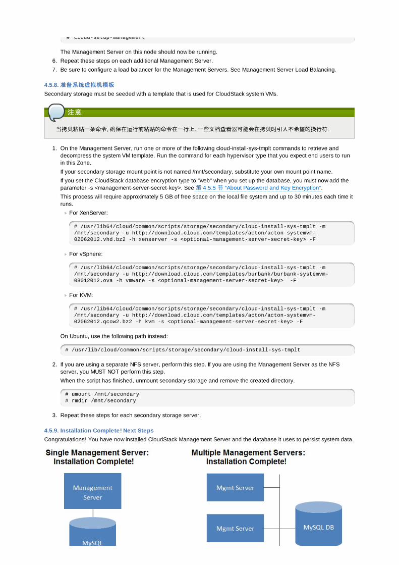
4.5.9. Installation Complete! Next StepsCongratulations! You have now installed CloudStack Management Server and the database it uses to persist system data.
What should you do next?
Even without adding any cloud infrastructure, you can run the UI to get a feel for what's offered and how you willinteract with CloudStack on an ongoing basis. See Log In to the UI.
When you're ready, add the cloud infrastructure and try running some virtual machines on it, so you can watch howCloudStack manages the infrastructure. See Provision Your Cloud Infrastructure.
第第 5 章章 用用户户界面界面
5.1. 登登陆陆到用到用户户界面界面CloudStack提供一个基于web的用户界面能够被管理员和终端用户使用。适当的用户界面版本被展现依赖于登陆时使用的凭证。用户界面是适用于大多数流行的浏览器包括IE7,IE8,IE9,Firefox3.5+,Firefox4,Safari4,和Safari5。URL是:(用你自己的管理控制服务器IP地址代替)
http://<管理控制-服务器-ip-地址>:8080/client
初次登陆管理控制服务器时,一个向导启动画面会显现。你将看到登陆界面当你执行下面的过程在你的控制面板上:
用用户户名名
你的帐户的用户标识。默认的用户名是admin。
密密码码
相关用户标识的密码。默认用户(admin)的密码是password。
域域
如果你是一个root用户,不用填写域这个字段。
如果你是一个子域的用户,输入完全路径在域字段,不包括根域。
例如,假设多个层级被建立在根域下,像Comp1/hr,在Comp1域的用户应该输入Comp1在域字段,在Comp1/sales域的用户应该输入Comp1/sales。
更多关于当你登陆这个界面时选项的指导,参照作为根管理员登陆。
5.1.1. 最最终终用用户户界面概界面概览览CloudStack 用户界面帮助云基础设施的用户查看和使用他们的云资源,包括虚拟机、模板和ISO、数据卷和快照、宾客网络,以及IP 地址。如果用户是一个或多个CloudStack 项目的成员或管理员,用户界面能提供一个面向项目的视图。
5.1.2. 根管理根管理员员界面的概述界面的概述
CloudStack 界面帮助 CloudStack 管理员配置,查看和管理云的基础设施,用户域,账号,项目,参数设置。当一个全新的管理服务器安装完成后,第一次启动界面的时候,可以选择根随引导步骤配置云的基础设施。当再次登录时,会显示当前登录用户的仪表板。在这个页面有很多的连接,可以通过左边的导航栏访问各种管理功能。根管理员也可以使用界面像最终用户一样来执行所有的功能。
5.1.3. 作作为为根管理根管理员员登登录录在管理服务器软件安装并且运行后, 你可以运行 CloudStack 的用户界面. 在这里通过UI,可以供给, 查看并管理你的云基础架构.
1. 打开你自己喜欢的浏览器并访问这个URL. 请把IP地址替换成你自己的管理服务器的IP.
http://<management-server-ip-address>:8080/client
After logging into a fresh Management Server installation, a guided tour splash screen appears. On later visits,you’ll be taken directly into the Dashboard.
2. 如果你看到第一次的向导屏幕, 可以选择下面步骤之一进行.
继续简单设继续简单设置置 . 如果你只是简单试用CloudStack,并且你想通过一个配置向导尽可能简单快速的开始, 请选择这项. 我们将帮助你建立一个有下列功能的云环境: 一个单独的机器运行CloudStack 并通过NFS提供存储; 一个单独的机器提供在XenServer或KVM上运行虚拟机; 以及一个共享的公共网络.
安装向导的提示应该给你需要的所有信息. 但如果你需要更多的详细信息, 你可以按照试用安装向导进行.
I have used CloudStack before. Choose this if you have already gone through a design phase and planned amore sophisticated deployment, or you are ready to start scaling up a trial cloud that you set up earlier with the
more sophisticated deployment, or you are ready to start scaling up a trial cloud that you set up earlier with thebasic setup screens. In the Administrator UI, you can start using the more powerful features of CloudStack, suchas advanced VLAN networking, high availability, additional network elements such as load balancers andfirewalls, and support for multiple hypervisors including Citrix XenServer, KVM, and VMware vSphere.
根管理员的仪表盘出现了.
3. 你应该为根管理员设置一个新的密码. 如果你选择简单设置, 将会提示你立即创建一个新的密码. 如果你选择有经验的用户, 请选择第 5.1.4 节 “修改Root口令”里的步骤.
警告警告
你正作为根管理员登入. 这个账号管理@PRODUCT;的部署, 包括物理架构. 根管理员可以更改配置以更改基本的功能,创建或删除用户账号, 以及其它许多只有被鉴权的用户执行的操作. 请更改默认的密码,确保其唯一性和安全性.
5.1.4. 修改修改Root口令口令During installation and ongoing cloud administration, you will need to log in to the UI as the root administrator. The rootadministrator account manages the CloudStack deployment, including physical infrastructure. The root administrator canmodify configuration settings to change basic functionality, create or delete user accounts, and take many actions thatshould be performed only by an authorized person. When first installing CloudStack, be sure to change the defaultpassword to a new, unique value.
1. 打开你自己喜欢的浏览器并访问这个URL. 请把IP地址替换成你自己的管理服务器的IP.
http://<management-server-ip-address>:8080/client
2. 使用当前root用户的ID和口令登录UI。缺省为admin/pawword。
3. 点击账户4. 点击管理员账户名5. 点击查看用户6. 点击管理员用户名
7. Click the Change Password button.
8. 键入新密码,然后点击确认
5.2. Using SSH Keys for AuthenticationIn addition to the username and password authentication, CloudStack supports using SSH keys to log in to the cloudinfrastructure for additional security. You can use the createSSHKeyPair API to generate the SSH keys.
Because each cloud user has their own SSH key, one cloud user cannot log in to another cloud user's instances unlessthey share their SSH key files. Using a single SSH key pair, you can manage multiple instances.
5.2.1. Creating an Instance Template that Supports SSH KeysCreate a instance template that supports SSH Keys.
1. Create a new instance by using the template provided by cloudstack.
For more information on creating a new instance, see
2. Download the cloudstack script from The SSH Key Gen Scriptto the instance you have created.
wget http://downloads.sourceforge.net/project/cloudstack/SSH%20Key%20Gen%20Script/cloud-set-guest-sshkey.in?r=http%3A%2F%2Fsourceforge.net%2Fprojects%2Fcloudstack%2Ffiles%2FSSH%2520Key%2520Gen%2520Script%2F&ts=1331225219&use_mirror=iweb
3. Copy the file to /etc/init.d.
cp cloud-set-guest-sshkey.in /etc/init.d/
4. Give the necessary permissions on the script:
chmod +x /etc/init.d/cloud-set-guest-sshkey.in
5. Run the script while starting up the operating system:
chkconfig --add cloud-set-guest-sshkey.in
6. Stop the instance.
5.2.2. Creating the SSH Keypair
5.2.2. Creating the SSH KeypairYou must make a call to the createSSHKeyPair api method. You can either use the CloudStack Python API library or thecurl commands to make the call to the cloudstack api.
For example, make a call from the cloudstack server to create a SSH keypair called "keypair-doc" for the admin account inthe root domain:
注意注意
Ensure that you adjust these values to meet your needs. If you are making the API call from a different server, yourURL/PORT will be different, and you will need to use the API keys.
1. Run the following curl command:
curl --globoff "http://localhost:8096/?command=createSSHKeyPair&name=keypair-doc&account=admin&domainid=5163440e-c44b-42b5-9109-ad75cae8e8a2"
The output is something similar to what is given below:
<?xml version="1.0" encoding="ISO-8859-1"?><createsshkeypairresponse cloud-stack-version="3.0.0.20120228045507"><keypair><name>keypair-doc</name><fingerprint>f6:77:39:d5:5e:77:02:22:6a:d8:7f:ce:ab:cd:b3:56</fingerprint><privatekey>-----BEGIN RSA PRIVATE KEY-----MIICXQIBAAKBgQCSydmnQ67jP6lNoXdX3noZjQdrMAWNQZ7y5SrEu4wDxplvhYcidXYBeZVwakDVsU2MLGl/K+wefwefwefwefwefJyKJaogMKn7BperPD6n1wIDAQABAoGAdXaJ7uyZKeRDoy6wA0UmF0kSPbMZCR+UTIHNkS/E0/4U+6lhMokmFSHtumfDZ1kGGDYhMsdytjDBztljawfawfeawefawfawfawQQDCjEsoRdgkduTyQpbSGDIa11Jsc+XNDx2fgRinDsxXI/zJYXTKRhSl/LIPHBw/brW8vzxhOlSOrwm7VvemkkgpAkEAwSeEw394LYZiEVv395ar9MLRVTVLwpo54jC4tsOxQCBlloocKlYaocpk0yBqqOUSBawfIiDCuLXSdvBo1Xz5ICTM19vgvEp/+kMuECQBzmnVo8b2Gvyagqt/KEQo8wzH2THghZ1qQ1QRhIeJG2aissEacF6bGB2oZ7Igim5L144KR7OeEToyCLC2k+02UCQQCrniSnWKtDVoVqeK/zbB32JhW3Wullv5p5zUEcdKfEEuzcCUIxtJYTahJ1pvlFkQ8anpuxjSEDp8x/18bq3-----END RSA PRIVATE KEY-----</privatekey></keypair></createsshkeypairresponse>
2. Copy the key data into a file. The file looks like this:
-----BEGIN RSA PRIVATE KEY-----MIICXQIBAAKBgQCSydmnQ67jP6lNoXdX3noZjQdrMAWNQZ7y5SrEu4wDxplvhYcidXYBeZVwakDVsU2MLGl/K+wefwefwefwefwefJyKJaogMKn7BperPD6n1wIDAQABAoGAdXaJ7uyZKeRDoy6wA0UmF0kSPbMZCR+UTIHNkS/E0/4U+6lhMokmFSHtumfDZ1kGGDYhMsdytjDBztljawfawfeawefawfawfawQQDCjEsoRdgkduTyQpbSGDIa11Jsc+XNDx2fgRinDsxXI/zJYXTKRhSl/LIPHBw/brW8vzxhOlSOrwm7VvemkkgpAkEAwSeEw394LYZiEVv395ar9MLRVTVLwpo54jC4tsOxQCBlloocKlYaocpk0yBqqOUSBawfIiDCuLXSdvBo1Xz5ICTM19vgvEp/+kMuECQBzmnVo8b2Gvyagqt/KEQo8wzH2THghZ1qQ1QRhIeJG2aissEacF6bGB2oZ7Igim5L144KR7OeEToyCLC2k+02UCQQCrniSnWKtDVoVqeK/zbB32JhW3Wullv5p5zUEcdKfEEuzcCUIxtJYTahJ1pvlFkQ8anpuxjSEDp8x/18bq3-----END RSA PRIVATE KEY-----
3. Save the file.
5.2.3. Creating an InstanceAfter you save the SSH keypair file, you must create an instance by using the template that you created at 第 5.2.1 节 “Creating an Instance Template that Supports SSH Keys”. Ensure that you use the same SSH key name that you created at第 5.2.2 节 “Creating the SSH Keypair”.
注意注意
You cannot create the instance by using the GUI at this time and associate the instance with the newly created SSHkeypair.
A sample curl command to create a new instance is:
curl --globoff http://localhost:<port numbet>/?command=deployVirtualMachine\&zoneId=1\&serviceOfferingId=18727021-7556-4110-9322-d625b52e0813\&templateId=e899c18a-ce13-4bbf-98a9-625c5026e0b5\&securitygroupids=ff03f02f-9e3b-48f8-834d-91b822da40c5\&account=admin\&domainid=1\&keypair=keypair-doc
Substitute the template, service offering and security group IDs (if you are using the security group feature) that are in
Substitute the template, service offering and security group IDs (if you are using the security group feature) that are inyour cloud environment.
5.2.4. Logging In Using the SSH KeypairTo test your SSH key generation is successful, check whether you can log in to the cloud setup.
For exaple, from a Linux OS, run:
ssh -i ~/.ssh/keypair-doc <ip address>
The -i parameter tells the ssh client to use a ssh key found at ~/.ssh/keypair-doc.
5.2.5. Resetting SSH KeysWith the API command resetSSHKeyForVirtualMachine, a user can set or reset the SSH keypair assigned to a virtualmachine. A lost or compromised SSH keypair can be changed, and the user can access the VM by using the new keypair.Just create or register a new keypair, then call resetSSHKeyForVirtualMachine.
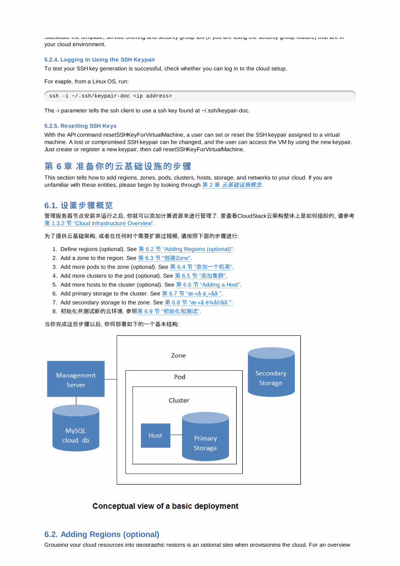
第第 6 章章 准准备备你的云基你的云基础设础设施的步施的步骤骤This section tells how to add regions, zones, pods, clusters, hosts, storage, and networks to your cloud. If you areunfamiliar with these entities, please begin by looking through 第 2 章 云基础设施概念.
6.1. 设设置步置步骤骤概概览览管理服务器节点安装并运行之后, 你就可以添加计算资源来进行管理了. 要查看CloudStack云架构整体上是如何组织的, 请参考第 1.3.2 节 “Cloud Infrastructure Overview”.
为了提供云基础架构, 或者在任何时个需要扩展过规模, 请按照下面的步骤进行:
1. Define regions (optional). See 第 6.2 节 “Adding Regions (optional)”.
2. Add a zone to the region. See 第 6.3 节 “创建Zone”.
3. Add more pods to the zone (optional). See 第 6.4 节 “添加一个机架”.
4. Add more clusters to the pod (optional). See 第 6.5 节 “添加集群”.
5. Add more hosts to the cluster (optional). See 第 6.6 节 “Adding a Host”.
6. Add primary storage to the cluster. See 第 6.7 节 “æ·»å 主å å ¨”.7. Add secondary storage to the zone. See 第 6.8 节 “æ·»å è¾ å ©å å ¨”.8. 初始化并测试新的云环境. 参照第 6.9 节 “初始化和测试”.
当你完成这些步骤以后, 你将部署如下的一个基本结构:
6.2. Adding Regions (optional)Grouping your cloud resources into geographic regions is an optional step when provisioning the cloud. For an overview
Grouping your cloud resources into geographic regions is an optional step when provisioning the cloud. For an overviewof regions, see 第 2.1 节 “About Regions”.
6.2.1. The First Region: The Default RegionIf you do not take action to define regions, then all the zones in your cloud will be automatically grouped into a singledefault region. This region is assigned the region ID of 1.
You can change the name or URL of the default region by using the API command updateRegion. For example:
http://<IP_of_Management_Server>:8080/client/api?command=updateRegion&id=1&name=Northern&endpoint=http://<region_1_IP_address_here>:8080/client&apiKey=miVr6X7u6bN_sdahOBpjNejPgEsT35eXq-jB8CG20YI3yaxXcgpyuaIRmFI_EJTVwZ0nUkkJbPmY3y2bciKwFQ&signature=Lxx1DM40AjcXU%2FcaiK8RAP0O1hU%3D
6.2.2. Adding a RegionUse these steps to add a second region in addition to the default region.
1. Each region has its own CloudStack instance. Therefore, the first step of creating a new region is to install theManagement Server software, on one or more nodes, in the geographic area where you want to set up the newregion. Use the steps in the Installation guide. When you come to the step where you set up the database, use theadditional command-line flag -r <region_id> to set a region ID for the new region. The default region isautomatically assigned a region ID of 1, so your first additional region might be region 2.
cloud-setup-databases cloud:<dbpassword>@localhost --deploy-as=root:<password> -e <encryption_type> -m <management_server_key> -k <database_key> -r <region_id>
2. By the end of the installation procedure, the Management Server should have been started. Be sure that theManagement Server installation was successful and complete.
3. Add region 2 to region 1. Use the API command addRegion. (For information about how to make an API call, see theDeveloper's Guide.)
http://<IP_of_region_1_Management_Server>:8080/client/api?command=addRegion&id=2&name=Western&endpoint=http://<region_2_IP_address_here>:8080/client&apiKey=miVr6X7u6bN_sdahOBpjNejPgEsT35eXq-jB8CG20YI3yaxXcgpyuaIRmFI_EJTVwZ0nUkkJbPmY3y2bciKwFQ&signature=Lxx1DM40AjcXU%2FcaiK8RAP0O1hU%3D
4. Now perform the same command in reverse, adding region 1 to region 2.
http://<IP_of_region_2_Management_Server>:8080/client/api?command=addRegion&id=2&name=Western&endpoint=http://<region_1_IP_address_here>:8080/client&apiKey=miVr6X7u6bN_sdahOBpjNejPgEsT35eXq-jB8CG20YI3yaxXcgpyuaIRmFI_EJTVwZ0nUkkJbPmY3y2bciKwFQ&signature=Lxx1DM40AjcXU%2FcaiK8RAP0O1hU%3D
5. Copy the account, user, and domain tables from the region 1 database to the region 2 database.
In the following commands, it is assumed that you have set the root password on the database, which is aCloudStack recommended best practice. Substitute your own MySQL root password.
a. First, run this command to copy the contents of the database:
# mysqldump -u root -p<mysql_password> -h <region1_db_host> cloud account user domain > region1.sql
b. Then run this command to put the data onto the region 2 database:
# mysql -u root -p<mysql_password> -h <region2_db_host> cloud < region1.sql
6. Remove project accounts. Run these commands on the region 2 database:
mysql> delete from account where type = 5;
7. Set the default zone as null:
mysql> update account set default_zone_id = null;
8. Restart the Management Servers in region 2.
6.2.3. Adding Third and Subsequent RegionsTo add the third region, and subsequent additional regions, the steps are similar to those for adding the second region.However, you must repeat certain steps additional times for each additional region:
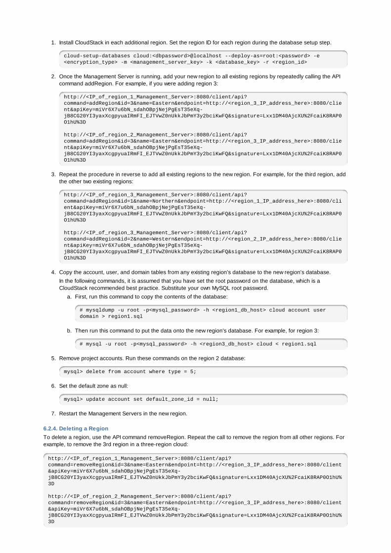
1. Install CloudStack in each additional region. Set the region ID for each region during the database setup step.
cloud-setup-databases cloud:<dbpassword>@localhost --deploy-as=root:<password> -e <encryption_type> -m <management_server_key> -k <database_key> -r <region_id>
2. Once the Management Server is running, add your new region to all existing regions by repeatedly calling the APIcommand addRegion. For example, if you were adding region 3:
http://<IP_of_region_1_Management_Server>:8080/client/api?command=addRegion&id=3&name=Eastern&endpoint=http://<region_3_IP_address_here>:8080/client&apiKey=miVr6X7u6bN_sdahOBpjNejPgEsT35eXq-jB8CG20YI3yaxXcgpyuaIRmFI_EJTVwZ0nUkkJbPmY3y2bciKwFQ&signature=Lxx1DM40AjcXU%2FcaiK8RAP0O1hU%3D
http://<IP_of_region_2_Management_Server>:8080/client/api?command=addRegion&id=3&name=Eastern&endpoint=http://<region_3_IP_address_here>:8080/client&apiKey=miVr6X7u6bN_sdahOBpjNejPgEsT35eXq-jB8CG20YI3yaxXcgpyuaIRmFI_EJTVwZ0nUkkJbPmY3y2bciKwFQ&signature=Lxx1DM40AjcXU%2FcaiK8RAP0O1hU%3D
3. Repeat the procedure in reverse to add all existing regions to the new region. For example, for the third region, addthe other two existing regions:
http://<IP_of_region_3_Management_Server>:8080/client/api?command=addRegion&id=1&name=Northern&endpoint=http://<region_1_IP_address_here>:8080/client&apiKey=miVr6X7u6bN_sdahOBpjNejPgEsT35eXq-jB8CG20YI3yaxXcgpyuaIRmFI_EJTVwZ0nUkkJbPmY3y2bciKwFQ&signature=Lxx1DM40AjcXU%2FcaiK8RAP0O1hU%3D
http://<IP_of_region_3_Management_Server>:8080/client/api?command=addRegion&id=2&name=Western&endpoint=http://<region_2_IP_address_here>:8080/client&apiKey=miVr6X7u6bN_sdahOBpjNejPgEsT35eXq-jB8CG20YI3yaxXcgpyuaIRmFI_EJTVwZ0nUkkJbPmY3y2bciKwFQ&signature=Lxx1DM40AjcXU%2FcaiK8RAP0O1hU%3D
4. Copy the account, user, and domain tables from any existing region's database to the new region's database.
In the following commands, it is assumed that you have set the root password on the database, which is aCloudStack recommended best practice. Substitute your own MySQL root password.
a. First, run this command to copy the contents of the database:
# mysqldump -u root -p<mysql_password> -h <region1_db_host> cloud account user domain > region1.sql
b. Then run this command to put the data onto the new region's database. For example, for region 3:
# mysql -u root -p<mysql_password> -h <region3_db_host> cloud < region1.sql
5. Remove project accounts. Run these commands on the region 2 database:
mysql> delete from account where type = 5;
6. Set the default zone as null:
mysql> update account set default_zone_id = null;
7. Restart the Management Servers in the new region.
6.2.4. Deleting a RegionTo delete a region, use the API command removeRegion. Repeat the call to remove the region from all other regions. Forexample, to remove the 3rd region in a three-region cloud:
http://<IP_of_region_1_Management_Server>:8080/client/api?command=removeRegion&id=3&name=Eastern&endpoint=http://<region_3_IP_address_here>:8080/client&apiKey=miVr6X7u6bN_sdahOBpjNejPgEsT35eXq-jB8CG20YI3yaxXcgpyuaIRmFI_EJTVwZ0nUkkJbPmY3y2bciKwFQ&signature=Lxx1DM40AjcXU%2FcaiK8RAP0O1hU%3D
http://<IP_of_region_2_Management_Server>:8080/client/api?command=removeRegion&id=3&name=Eastern&endpoint=http://<region_3_IP_address_here>:8080/client&apiKey=miVr6X7u6bN_sdahOBpjNejPgEsT35eXq-jB8CG20YI3yaxXcgpyuaIRmFI_EJTVwZ0nUkkJbPmY3y2bciKwFQ&signature=Lxx1DM40AjcXU%2FcaiK8RAP0O1hU%3D
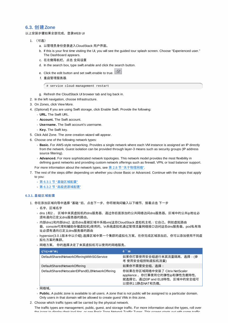
6.3. 创创建建Zone以上安装步骤如果全部完成,登录WEB UI
1. (可选)a. 以管理员身份登录进入CloudStack 用户界面。b. If this is your first time visiting the UI, you will see the guided tour splash screen. Choose “Experienced user.”
The Dashboard appears.
c. 在左侧导航栏,点击 全局设置d. In the search box, type swift.enable and click the search button.
e. Click the edit button and set swift.enable to true.
f. 重启管理服务器.
# service cloud-management restart
g. Refresh the CloudStack UI browser tab and log back in.
2. In the left navigation, choose Infrastructure.
3. On Zones, click View More.
4. (Optional) If you are using Swift storage, click Enable Swift. Provide the following:
URL. The Swift URL.
Account. The Swift account.
Username. The Swift account’s username.
Key. The Swift key.
5. Click Add Zone. The zone creation wizard will appear.
6. Choose one of the following network types:
Basic. For AWS-style networking. Provides a single network where each VM instance is assigned an IP directlyfrom the network. Guest isolation can be provided through layer-3 means such as security groups (IP addresssource filtering).
Advanced. For more sophisticated network topologies. This network model provides the most flexibility indefining guest networks and providing custom network offerings such as firewall, VPN, or load balancer support.
For more information about the network types, see 第 2.8 节 “关于物理网络”.
7. The rest of the steps differ depending on whether you chose Basic or Advanced. Continue with the steps that applyto you:
第 6.3.1 节 “基础区域配置”
第 6.3.2 节 “高级资源域配置”
6.3.1. 基基础础区域配置区域配置
1. 你在添加区域向导中选择 ”基础 “后,点击下一步,你将被询问输入以下细节,接着点击 下一步
名字,区域名字
dns 1和2 , 区域中来宾虚拟机的dns服务器,通过你后面添加的公共网络访问dns服务器。区域中的公共ip地址必须有通向已定义dns服务器的路由。内部dns1和内部dns2. 这些dns是被区域中系统vm(这些CloudStack 虚拟机主机:它自己。例如虚拟路由器,console代理和辅助存储虚拟机)使用的。\n系统虚拟机通过管理流量网络接口访问这些dns服务器。pod私有地址必须有通向已定义dns服务器的路由hypersior(3.0.1版本中以介绍).选择区域中第一个集群的虚拟化方案。在你完成区域添加后,你可以添加使用不同虚拟化方案的集群。网络方案。 你的选择决定了来宾虚拟机可以使用的网络服务。
ç½ ç» æ ¹æ¡ è¯´æ DefaultSharedNetworkOfferingWithSGService 如果你打算使用安全组进行来宾流量隔离,选择:(参
考 使用安全组控制虚拟机流量)
DefaultSharedNetworkOffering 如果你不需要安全组,选择:DefaultSharedNetscalerEIPandELBNetworkOffering 你如果在你区域网络中安装了 Citrix NetScaler
appliance ,你打算使用它的弹性ip和弹性负载特性,就选择它。通过EIP and ELB特性,区域中的安全组可以提供1:1静态NAT和负载。
网络域。Public. A public zone is available to all users. A zone that is not public will be assigned to a particular domain.Only users in that domain will be allowed to create guest VMs in this zone.
2. Choose which traffic types will be carried by the physical network.
The traffic types are management, public, guest, and storage traffic. For more information about the types, roll overthe icons to display their tool tips, or see Basic Zone Network Traffic Types. This screen starts out with some traffic

the icons to display their tool tips, or see Basic Zone Network Traffic Types. This screen starts out with some traffictypes already assigned. To add more, drag and drop traffic types onto the network. You can also change thenetwork name if desired.
3. 3. (Introduced in version 3.0.1) Assign a network traffic label to each traffic type on the physical network. Theselabels must match the labels you have already defined on the hypervisor host. To assign each label, click the Editbutton under the traffic type icon. A popup dialog appears where you can type the label, then click OK.
These traffic labels will be defined only for the hypervisor selected for the first cluster. For all other hypervisors, thelabels can be configured after the zone is created.
4. Click Next.
5. (NetScaler only) If you chose the network offering for NetScaler, you have an additional screen to fill out. Providethe requested details to set up the NetScaler, then click Next.
IP address. The NSIP (NetScaler IP) address of the NetScaler device.
Username/Password. The authentication credentials to access the device. CloudStack uses these credentialsto access the device.
Type. NetScaler device type that is being added. It could be NetScaler VPX, NetScaler MPX, or NetScaler SDX.For a comparison of the types, see About Using a NetScaler Load Balancer.
Public interface. Interface of NetScaler that is configured to be part of the public network.
Private interface. Interface of NetScaler that is configured to be part of the private network.
Number of retries. Number of times to attempt a command on the device before considering the operationfailed. Default is 2.
Capacity. Number of guest networks/accounts that will share this NetScaler device.
Dedicated. When marked as dedicated, this device will be dedicated to a single account. When Dedicated ischecked, the value in the Capacity field has no significance – implicitly, its value is 1.
6. (NetScaler only) Configure the IP range for public traffic. The IPs in this range will be used for the static NATcapability which you enabled by selecting the network offering for NetScaler with EIP and ELB. Enter the followingdetails, then click Add. If desired, you can repeat this step to add more IP ranges. When done, click Next.
Gateway. The gateway in use for these IP addresses.
Netmask. The netmask associated with this IP range.
VLAN. The VLAN that will be used for public traffic.
Start IP/End IP. A range of IP addresses that are assumed to be accessible from the Internet and will beallocated for access to guest VMs.
7. In a new zone, CloudStack adds the first pod for you. You can always add more pods later. For an overview of whata pod is, see 第 2.3 节 “关于POD”.
To configure the first pod, enter the following, then click Next:
Pod Name. A name for the pod.
Reserved system gateway. The gateway for the hosts in that pod.
Reserved system netmask. The network prefix that defines the pod's subnet. Use CIDR notation.
Start/End Reserved System IP. The IP range in the management network that CloudStack uses to managevarious system VMs, such as Secondary Storage VMs, Console Proxy VMs, and DHCP. For more information,see System Reserved IP Addresses.
8. Configure the network for guest traffic. Provide the following, then click Next:
Guest gateway. The gateway that the guests should use.
Guest netmask. The netmask in use on the subnet the guests will use.
Guest start IP/End IP. Enter the first and last IP addresses that define a range that CloudStack can assign toguests.
We strongly recommend the use of multiple NICs. If multiple NICs are used, they may be in a different subnet.
If one NIC is used, these IPs should be in the same CIDR as the pod CIDR.
9. In a new pod, CloudStack adds the first cluster for you. You can always add more clusters later. For an overview ofwhat a cluster is, see About Clusters.
To configure the first cluster, enter the following, then click Next:
Hypervisor. (Version 3.0.0 only; in 3.0.1, this field is read only) Choose the type of hypervisor software that allhosts in this cluster will run. If you choose VMware, additional fields appear so you can give information about avSphere cluster. For vSphere servers, we recommend creating the cluster of hosts in vCenter and then addingthe entire cluster to CloudStack. See Add Cluster: vSphere.
Cluster name. Enter a name for the cluster. This can be text of your choosing and is not used by CloudStack.
10. In a new cluster, CloudStack adds the first host for you. You can always add more hosts later. For an overview ofwhat a host is, see About Hosts.
注意注意
When you add a hypervisor host to CloudStack, the host must not have any VMs already running.
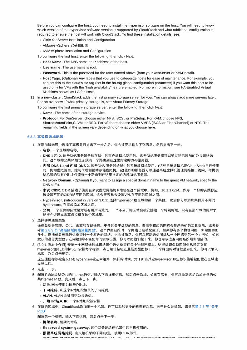
Before you can configure the host, you need to install the hypervisor software on the host. You will need to knowwhich version of the hypervisor software version is supported by CloudStack and what additional configuration isrequired to ensure the host will work with CloudStack. To find these installation details, see:
Citrix XenServer Installation and Configuration
VMware vSphere 安装和配置
KVM vSphere Installation and Configuration
To configure the first host, enter the following, then click Next:
Host Name. The DNS name or IP address of the host.
Username. The username is root.
Password. This is the password for the user named above (from your XenServer or KVM install).
Host Tags. (Optional) Any labels that you use to categorize hosts for ease of maintenance. For example, youcan set this to the cloud's HA tag (set in the ha.tag global configuration parameter) if you want this host to beused only for VMs with the "high availability" feature enabled. For more information, see HA-Enabled VirtualMachines as well as HA for Hosts.
11. In a new cluster, CloudStack adds the first primary storage server for you. You can always add more servers later.For an overview of what primary storage is, see About Primary Storage.
To configure the first primary storage server, enter the following, then click Next:
Name. The name of the storage device.
Protocol. For XenServer, choose either NFS, iSCSI, or PreSetup. For KVM, choose NFS,SharedMountPoint,CLVM, or RBD. For vSphere choose either VMFS (iSCSI or FiberChannel) or NFS. Theremaining fields in the screen vary depending on what you choose here.
6.3.2. 高高级资级资源域配置源域配置
1. 在添加域向导中选择了高级并且点击下一步之后,你会被要求输入下列信息。然后点击下一步。名称名称 . 一个区域的名称。DNS 1 和和 2. 这些DNS服务器是给在域中的客户虚拟机使用的。这些DNS服务器可以通过稍后添加的公共网络访问。这个域的公共IP 地址必须有一个路由到在这里指定的DNS服务器。内部内部 DNS 1 and 内部内部 DNS 2. 这些DNS 服务器给域中的系统虚拟机使用。(这些系统虚拟机是CloudStack自己使用的,例如虚拟路由,控制代理和辅助存储虚拟机。)这些DNS服务器可以通过系统虚拟机管理网络接口访问。你提供给机架的私有IP地址必须有一个路由到在这里指定的内部DNS服务器。Network Domain. (Optional) If you want to assign a special domain name to the guest VM network, specify theDNS suffix.
来来宾宾 CIDR. CIDR 描述了使用在来宾虚拟网络的IP地址在这个区域中。例如,10.1.1.0/24。作为一个好的实践你应该设置不同的CIDR给不同的区域。这会更容易去设置VPN在不同的区域之间。Hypervisor. (Introduced in version 3.0.1) 选择hypervisor 给区域的第一个集群。 之后你可以添加集群用不同的hypervisors, 在完成添加区域之后。
公共公共 . 一个公共的区域是对所有用户有效的。一个不公开的区域会被安排给一个特别的域。只有在那个域的用户才能被允许建立来宾虚拟机在这个区域里。
2. 选择哪种通信类型通信类型是管理,公共,来宾和存储通信。更多的关于类型的信息,覆盖到相应的图标会显示他们的工具提示,或者参考第 2.8.3 节 “高级区域网络流量类型”。这个界面初始时一个网络已经被配置了。如果你有多个物理网络,你需要添加多个。拖拽或者删除通信类型对一个灰色的网络,它会被激活。你可以移动通信图标从一个网络到另一个;例如,如果默认的通信类型显示在网络1的不匹配你的实际设置,你可以把他们拉下来。你也可以改变网络名按照你期望的。
3. (3.0.1 版本中介绍) 安排一个网络通信标识给每个通信类型在每个物理网络上。这些标识必须匹配你已经定义在hypervisor主机上的标识。安排每个标识,点击编辑按钮在通信类型图标下,一个弹出的对话框显示出来,你可以输入标识,然后点击确定。这些通信标识被定义只有hypervisor被选中给第一集群的时候。对于所有其它hypervisor,那些标识能够被配置在区域建立好以后。
4. 点击下一步。5. 配置IP地址段给公共的Internet通信。输入下面详细信息,然后点击添加。如果有需要,你可以重复这步添加更多的公共Internet IP 段。完成后,点击下一步。网关网关 .网关使用为这些IP地址。
子网掩子网掩码码 . 和这个IP地址段相关的子网掩码。VLAN. VLAN 会被用到公共通信。
开始开始 IP/结结束束 IP. 一个IP地址段被安排
6. 在新的区域中,CloudStack添加第一个机架。你可以添加更多的机架在以后。关于什么是机架,请参考第 2.3 节 “关于POD”
配置第一个机架,输入下面信息,然后点击下一步:机架名称机架名称 . 机架的命名.
Reserved system gateway. 这个网关是给在机架中的主机使用的。预预留系留系统统网网络络掩掩码码 . 定义给机架的子网前缀。 使用CIDR形式。
开始开始 /结结束束 预预留系留系统统 IP. 管理网络中的IP地址段,CloudStack 用来管理各种系统虚拟机, 例如辅助存储系统虚拟机,
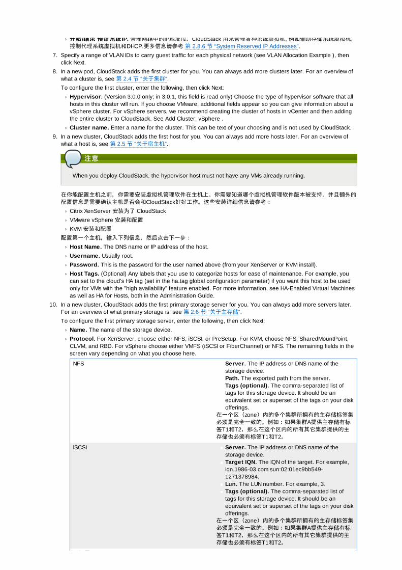
开始开始 /结结束束 预预留系留系统统 IP. 管理网络中的IP地址段,CloudStack 用来管理各种系统虚拟机, 例如辅助存储系统虚拟机,控制代理系统虚拟机和DHCP.更多信息请参考 第 2.8.6 节 “System Reserved IP Addresses”.
7. Specify a range of VLAN IDs to carry guest traffic for each physical network (see VLAN Allocation Example ), thenclick Next.
8. In a new pod, CloudStack adds the first cluster for you. You can always add more clusters later. For an overview ofwhat a cluster is, see 第 2.4 节 “关于集群”.
To configure the first cluster, enter the following, then click Next:
Hypervisor. (Version 3.0.0 only; in 3.0.1, this field is read only) Choose the type of hypervisor software that allhosts in this cluster will run. If you choose VMware, additional fields appear so you can give information about avSphere cluster. For vSphere servers, we recommend creating the cluster of hosts in vCenter and then addingthe entire cluster to CloudStack. See Add Cluster: vSphere .
Cluster name. Enter a name for the cluster. This can be text of your choosing and is not used by CloudStack.
9. In a new cluster, CloudStack adds the first host for you. You can always add more hosts later. For an overview ofwhat a host is, see 第 2.5 节 “关于宿主机”.
注意注意
When you deploy CloudStack, the hypervisor host must not have any VMs already running.
在你能配置主机之前,你需要安装虚拟机管理软件在主机上。你需要知道哪个虚拟机管理软件版本被支持,并且额外的配置信息是需要确认主机是否会和CloudStack好好工作。这些安装详细信息请参考:
Citrix XenServer 安装为了 CloudStack
VMware vSphere 安装和配置
KVM 安装和配置
配置第一个主机,输入下列信息,然后点击下一步:Host Name. The DNS name or IP address of the host.
Username. Usually root.
Password. This is the password for the user named above (from your XenServer or KVM install).
Host Tags. (Optional) Any labels that you use to categorize hosts for ease of maintenance. For example, youcan set to the cloud's HA tag (set in the ha.tag global configuration parameter) if you want this host to be usedonly for VMs with the "high availability" feature enabled. For more information, see HA-Enabled Virtual Machinesas well as HA for Hosts, both in the Administration Guide.
10. In a new cluster, CloudStack adds the first primary storage server for you. You can always add more servers later.For an overview of what primary storage is, see 第 2.6 节 “关于主存储”.
To configure the first primary storage server, enter the following, then click Next:
Name. The name of the storage device.
Protocol. For XenServer, choose either NFS, iSCSI, or PreSetup. For KVM, choose NFS, SharedMountPoint,CLVM, and RBD. For vSphere choose either VMFS (iSCSI or FiberChannel) or NFS. The remaining fields in thescreen vary depending on what you choose here.
NFS Server. The IP address or DNS name of thestorage device.Path. The exported path from the server.Tags (optional). The comma-separated list oftags for this storage device. It should be anequivalent set or superset of the tags on your diskofferings.
在一个区(zone)内的多个集群所拥有的主存储标签集必须是完全一致的。例如:如果集群A提供主存储有标签T1和T2,那么在这个区内的所有其它集群提供的主存储也必须有标签T1和T2。
iSCSI Server. The IP address or DNS name of thestorage device.Target IQN. The IQN of the target. For example,iqn.1986-03.com.sun:02:01ec9bb549-1271378984.Lun. The LUN number. For example, 3.Tags (optional). The comma-separated list oftags for this storage device. It should be anequivalent set or superset of the tags on your diskofferings.
在一个区(zone)内的多个集群所拥有的主存储标签集必须是完全一致的。例如:如果集群A提供主存储有标签T1和T2,那么在这个区内的所有其它集群提供的主存储也必须有标签T1和T2。
预设置 Server. The IP address or DNS name of the
预设置 Server. The IP address or DNS name of thestorage device.SR Name-Label. 输入已经安装在CloudStack之外的SR名称标识。Tags (optional). The comma-separated list oftags for this storage device. It should be anequivalent set or superset of the tags on your diskofferings.
在一个区(zone)内的多个集群所拥有的主存储标签集必须是完全一致的。例如:如果集群A提供主存储有标签T1和T2,那么在这个区内的所有其它集群提供的主存储也必须有标签T1和T2。
SharedMountPoint 路径路径 . 主存储被挂载到每个主机上的路径。例如,"/mnt/primary".Tags (optional). The comma-separated list oftags for this storage device. It should be anequivalent set or superset of the tags on your diskofferings.
在一个区(zone)内的多个集群所拥有的主存储标签集必须是完全一致的。例如:如果集群A提供主存储有标签T1和T2,那么在这个区内的所有其它集群提供的主存储也必须有标签T1和T2。
VMFS 服服务务器器 . vCenter服务器的IP地址或者是DNS名称。路径路径 . 一个数据中心和数据存储合并的名称。格式是 "/" 数据中心名 "/" 数据存储名。例如,"/cloud.dc.VM/cluster1datastore".Tags (optional). The comma-separated list oftags for this storage device. It should be anequivalent set or superset of the tags on your diskofferings.
在一个区(zone)内的多个集群所拥有的主存储标签集必须是完全一致的。例如:如果集群A提供主存储有标签T1和T2,那么在这个区内的所有其它集群提供的主存储也必须有标签T1和T2。
11. 在这个新区域中,CloudStack添加第一个辅助存储服务器给你。对于辅助存储概览,请参考第 2.7 节 “关与辅助存储”。
在你填写这个界面之前,你需要提前准备好辅助存储通过设置NFS共享并且安装最新版本的CloudStack系统虚拟机模板。参考添加辅助存储。
NFS 服服务务器器 . NFS 服务器的IP地址。
Path. The exported path from the server.
12. 点击启动。
6.4. 添加一个机架添加一个机架When you created a new zone, CloudStack adds the first pod for you. You can add more pods at any time using theprocedure in this section.
1. Log in to the CloudStack UI. See 第 5.1 节 “登陆到用户界面”.
2. In the left navigation, choose Infrastructure. In Zones, click View More, then click the zone to which you want to adda pod.
3. Click the Compute and Storage tab. In the Pods node of the diagram, click View All.
4. Click Add Pod.
5. Enter the following details in the dialog.
Name. The name of the pod.
Gateway. The gateway for the hosts in that pod.
Netmask. The network prefix that defines the pod's subnet. Use CIDR notation.
Start/End Reserved System IP. The IP range in the management network that CloudStack uses to managevarious system VMs, such as Secondary Storage VMs, Console Proxy VMs, and DHCP. For more information,see System Reserved IP Addresses.
6. 点击 确定。
6.5. 添加集群添加集群你需要告诉CloudStack 它要管理的主机。主机存在于集群中,所以在你开始加入主机到云中之前,你必须增加至少一个集群。
6.5.1. Add Cluster: KVM or XenServer
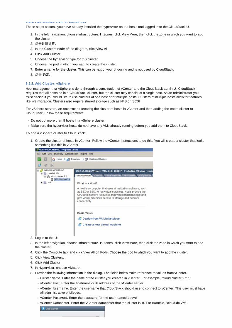
6.5.1. Add Cluster: KVM or XenServerThese steps assume you have already installed the hypervisor on the hosts and logged in to the CloudStack UI.
1. In the left navigation, choose Infrastructure. In Zones, click View More, then click the zone in which you want to addthe cluster.
2. 点击计算标签。3. In the Clusters node of the diagram, click View All.
4. Click Add Cluster.
5. Choose the hypervisor type for this cluster.
6. Choose the pod in which you want to create the cluster.
7. Enter a name for the cluster. This can be text of your choosing and is not used by CloudStack.
8. 点击 确定。
6.5.2. Add Cluster: vSphereHost management for vSphere is done through a combination of vCenter and the CloudStack admin UI. CloudStackrequires that all hosts be in a CloudStack cluster, but the cluster may consist of a single host. As an administrator youmust decide if you would like to use clusters of one host or of multiple hosts. Clusters of multiple hosts allow for featureslike live migration. Clusters also require shared storage such as NFS or iSCSI.
For vSphere servers, we recommend creating the cluster of hosts in vCenter and then adding the entire cluster toCloudStack. Follow these requirements:
Do not put more than 8 hosts in a vSphere cluster
Make sure the hypervisor hosts do not have any VMs already running before you add them to CloudStack.
To add a vSphere cluster to CloudStack:
1. Create the cluster of hosts in vCenter. Follow the vCenter instructions to do this. You will create a cluster that lookssomething like this in vCenter.
2. Log in to the UI.
3. In the left navigation, choose Infrastructure. In Zones, click View More, then click the zone in which you want to addthe cluster.
4. Click the Compute tab, and click View All on Pods. Choose the pod to which you want to add the cluster.
5. Click View Clusters.
6. Click Add Cluster.
7. In Hypervisor, choose VMware.
8. Provide the following information in the dialog. The fields below make reference to values from vCenter.
Cluster Name. Enter the name of the cluster you created in vCenter. For example, "cloud.cluster.2.2.1"
vCenter Host. Enter the hostname or IP address of the vCenter server.
vCenter Username. Enter the username that CloudStack should use to connect to vCenter. This user must haveall administrative privileges.
vCenter Password. Enter the password for the user named above
vCenter Datacenter. Enter the vCenter datacenter that the cluster is in. For example, "cloud.dc.VM".
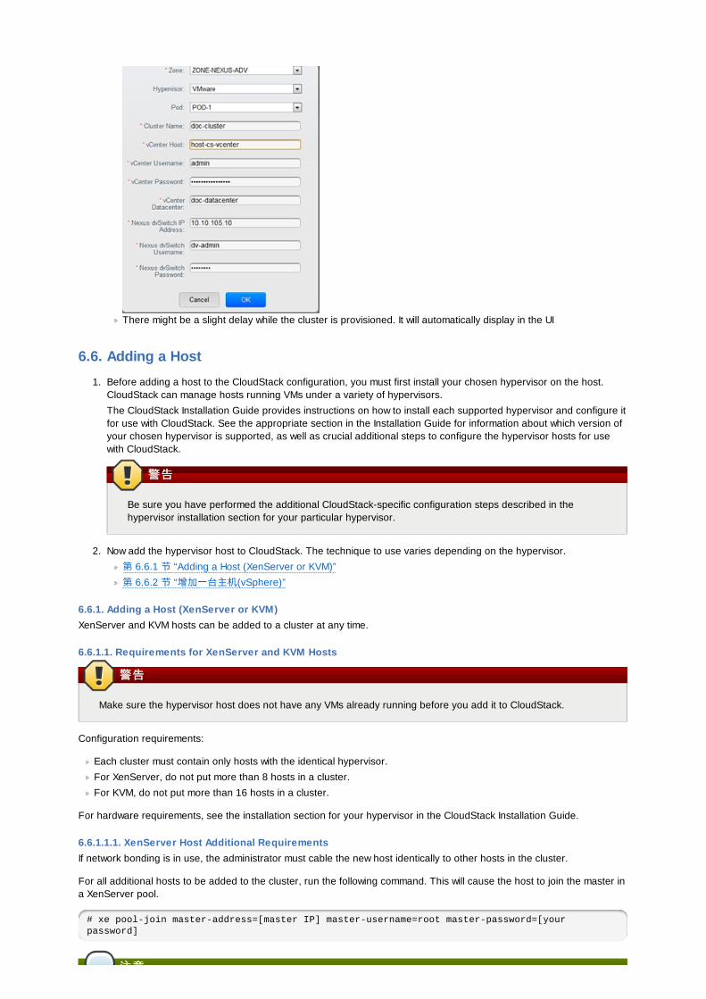
There might be a slight delay while the cluster is provisioned. It will automatically display in the UI
6.6. Adding a Host
1. Before adding a host to the CloudStack configuration, you must first install your chosen hypervisor on the host.CloudStack can manage hosts running VMs under a variety of hypervisors.
The CloudStack Installation Guide provides instructions on how to install each supported hypervisor and configure itfor use with CloudStack. See the appropriate section in the Installation Guide for information about which version ofyour chosen hypervisor is supported, as well as crucial additional steps to configure the hypervisor hosts for usewith CloudStack.
警告警告
Be sure you have performed the additional CloudStack-specific configuration steps described in thehypervisor installation section for your particular hypervisor.
2. Now add the hypervisor host to CloudStack. The technique to use varies depending on the hypervisor.
第 6.6.1 节 “Adding a Host (XenServer or KVM)”
第 6.6.2 节 “增加一台主机(vSphere)”
6.6.1. Adding a Host (XenServer or KVM)XenServer and KVM hosts can be added to a cluster at any time.
6.6.1.1. Requirements for XenServer and KVM Hosts
警告警告
Make sure the hypervisor host does not have any VMs already running before you add it to CloudStack.
Configuration requirements:
Each cluster must contain only hosts with the identical hypervisor.
For XenServer, do not put more than 8 hosts in a cluster.
For KVM, do not put more than 16 hosts in a cluster.
For hardware requirements, see the installation section for your hypervisor in the CloudStack Installation Guide.
6.6.1.1.1. XenServer Host Additional RequirementsIf network bonding is in use, the administrator must cable the new host identically to other hosts in the cluster.
For all additional hosts to be added to the cluster, run the following command. This will cause the host to join the master ina XenServer pool.
# xe pool-join master-address=[master IP] master-username=root master-password=[your password]
注意注意

注意注意
当拷贝粘贴一条命令, 确保在运行前粘贴的命令在一行上. 一些文档查看器可能会在拷贝时引入不希望的换行符.
With all hosts added to the XenServer pool, run the cloud-setup-bond script. This script will complete the configuration andsetup of the bonds on the new hosts in the cluster.
1. Copy the script from the Management Server in /usr/lib64/cloud/common/scripts/vm/hypervisor/xenserver/cloud-setup-bonding.sh to the master host and ensure it is executable.
2. 运行脚本。
# ./cloud-setup-bonding.sh
6.6.1.1.2. KVM Host Additional Requirements
If shared mountpoint storage is in use, the administrator should ensure that the new host has all the same mountpoints(with storage mounted) as the other hosts in the cluster.
Make sure the new host has the same network configuration (guest, private, and public network) as other hosts in thecluster.
If you are using OpenVswitch bridges edit the file agent.properties on the KVM host and set the parameternetwork.bridge.type to openvswitch before adding the host to CloudStack
6.6.1.2. Adding a XenServer or KVM Host
If you have not already done so, install the hypervisor software on the host. You will need to know which version of thehypervisor software version is supported by CloudStack and what additional configuration is required to ensure thehost will work with CloudStack. To find these installation details, see the appropriate section for your hypervisor in theCloudStack Installation Guide.
以管理员身份登录进入CloudStack 用户界面。In the left navigation, choose Infrastructure. In Zones, click View More, then click the zone in which you want to add thehost.
Click the Compute tab. In the Clusters node, click View All.
Click the cluster where you want to add the host.
Click View Hosts.
Click Add Host.
Provide the following information.
Host Name. The DNS name or IP address of the host.
Username. Usually root.
Password. This is the password for the user from your XenServer or KVM install).
Host Tags (Optional). Any labels that you use to categorize hosts for ease of maintenance. For example, you canset to the cloud's HA tag (set in the ha.tag global configuration parameter) if you want this host to be used only forVMs with the "high availability" feature enabled. For more information, see HA-Enabled Virtual Machines as well asHA for Hosts.
There may be a slight delay while the host is provisioned. It should automatically display in the UI.
Repeat for additional hosts.
6.6.2. 增加一台主机增加一台主机 (vSphere)对于 vSphere 服务器,我们建议在vCenter 中创建主机的集群并把整个集群加入到 CloudStack 中。见 Add Cluster:vSphere。
6.7. æ·»å 主åå¨
6.7.1. System Requirements for Primary StorageHardware requirements:
Any standards-compliant iSCSI or NFS server that is supported by the underlying hypervisor.
The storage server should be a machine with a large number of disks. The disks should ideally be managed by ahardware RAID controller.
Minimum required capacity depends on your needs.
When setting up primary storage, follow these restrictions:
Primary storage cannot be added until a host has been added to the cluster.
If you do not provision shared primary storage, you must set the global configuration parametersystem.vm.local.storage.required to true, or else you will not be able to start VMs.
system.vm.local.storage.required to true, or else you will not be able to start VMs.
6.7.2. Adding Primary Stroage当你建立一个新的区域的时候,主存储作为过程的一部分被添加。你也可以添加主存储在任何时候,例如当添加一个新的群集或者添加更多的主机到一个存在的群集的时候。
警告警告
Be sure there is nothing stored on the server. Adding the server to CloudStack will destroy any existing data.
1. Log in to the CloudStack UI (see 第 5.1 节 “登陆到用户界面”).
2. 在左边的导航栏,选择基础架构。在区域中,点击查看全部,然后点击你想添加主存储的那个区域。3. 点击计算标签。4. 在图的主存储节点,点击查看所有。5. 点击添加主存储。6. 在对话框中提供下面的信息。
Pod. The pod for the storage device.
Cluster. The cluster for the storage device.
Name. The name of the storage device.
Protocol. For XenServer, choose either NFS, iSCSI, or PreSetup. For KVM, choose NFS or SharedMountPoint.For vSphere choose either VMFS (iSCSI or FiberChannel) or NFS.
Server (for NFS, iSCSI, or PreSetup). The IP address or DNS name of the storage device.
Server (for VMFS). The IP address or DNS name of the vCenter server.
Path (for NFS). In NFS this is the exported path from the server.
Path (for VMFS). In vSphere this is a combination of the datacenter name and the datastore name. The formatis "/" datacenter name "/" datastore name. For example, "/cloud.dc.VM/cluster1datastore".
Path (for SharedMountPoint). With KVM this is the path on each host that is where this primary storage ismounted. For example, "/mnt/primary".
SR Name-Label (for PreSetup). Enter the name-label of the SR that has been set up outside CloudStack.
Target IQN (for iSCSI). In iSCSI this is the IQN of the target. For example, iqn.1986-03.com.sun:02:01ec9bb549-1271378984.
Lun # (for iSCSI). In iSCSI this is the LUN number. For example, 3.
Tags (optional). The comma-separated list of tags for this storage device. It should be an equivalent set orsuperset of the tags on your disk offerings..
在一个区(zone)内的多个集群所拥有的主存储标签集必须是完全一致的。例如:如果集群A提供主存储有标签T1和T2,那么在这个区内的所有其它集群提供的主存储也必须有标签T1和T2。
7. 点击 确定。
6.8. æ·»å è¾ å©åå¨
6.8.1. System Requirements for Secondary Storage
NFS storage appliance or Linux NFS server
(Optional) OpenStack Object Storage (Swift) (see http://swift.openstack.org)
100GB minimum capacity
A secondary storage device must be located in the same zone as the guest VMs it serves.
Each Secondary Storage server must be available to all hosts in the zone.
6.8.2. 增加二增加二级级存存储储When you create a new zone, the first secondary storage is added as part of that procedure. You can add secondarystorage servers at any time to add more servers to an existing zone.
警告警告
Be sure there is nothing stored on the server. Adding the server to CloudStack will destroy any existing data.
1. If you are going to use Swift for cloud-wide secondary storage, you must add the Swift storage to CloudStack beforeyou add the local zone secondary storage servers. See 第 6.3 节 “创建Zone”.
2. To prepare for local zone secondary storage, you should have created and mounted an NFS share duringManagement Server installation. See 第 4.5.6 节 “准备NFS共享”.
3. Make sure you prepared the system VM template during Management Server installation. See 第 4.5.8 节 “准备系统虚拟机模板”.
4. Now that the secondary storage server for per-zone storage is prepared, add it to CloudStack. Secondary storage isadded as part of the procedure for adding a new zone. See 第 6.3 节 “创建Zone”.
6.9. 初始化和初始化和测试测试所有内容配置好之后,执行初始化。根据你的网络速度,大概花费30分钟或更长时间。当初始化成功执行之后,管理面板会在CloudStack UI中显示。
1. 系统验证完成后,在左边的导航栏,选择模版,点击‘ CentOS 5.5 (64bit) no Gui (KVM) template’,在下载完成前不要做下一步操作。
2. 进入‘实例’标签,查看我的实例。3. 点击添加实例,进入导航。
a. 选择你添加的区域。b. 在选择模版中,选择要在虚拟机中使用的模版,如果是新安装的系统,只有CentOS模版供选择。c. 选择计算方案,确定硬件环境允许启动你选择的计算方案。d. 在磁盘方案中,如果需要,添加另一个数据磁盘。第二个卷可能不会挂载在虚拟机上。例如:在XenServer的
Linux下重启后你会看到/dev/xvdb。如果使用PV-enabled 的操作系统内核,则不需要重启。e. 在默认网络,为客户虚拟机选择主要网络。在试用安装中,在这里只有一个选项。f. 任意的为虚拟机添加名称和组。
g. Click Launch VM. Your VM will be created and started. It might take some time to download the template andcomplete the VM startup. You can watch the VM’s progress in the Instances screen.
4. 使用虚拟机,点击查看按钮
For more information about using VMs, including instructions for how to allow incoming network traffic to the VM,start, stop, and delete VMs, and move a VM from one host to another, see Working With Virtual Machines in theAdministrator’s Guide.
恭喜你,你成功完成了 CloudStack的安装
如果你决定增加你的部署,你可以增加更多的主机,主存储,区域,机架和集群
第第 7 章章 设设置全局配置参数置全局配置参数你可以通过设置CloudStack提供的参数控制云的多个方面.CloudStack首次安装后,在此后定期,您可能需要修改这些设置。
1. 使用管理员账号登陆2. 在左侧导航栏,点击 全局设置3. 在选择视图中,选择下列操作之一:
全局设置hypervsior 容量。这里显示列出了不同hypervsior版本所支持的最大虚拟机数量。
4. 使用搜索框来缩小列表中你所感兴趣的那些5. 单击“编辑”图标修改一个值。如果您正在查看的hypervsior容量,您必须单击hypervsior第一次显示编辑屏幕的名称。
第第 8 章章 虚虚拟拟化安装化安装
8.1. KVM Hypervisor Host Installation
8.1.1. System Requirements for KVM Hypervisor HostsKVM is included with a variety of Linux-based operating systems. Although you are not required to run these distributions,the following are recommended:
CentOS / RHEL: 6.3
Ubuntu: 12.04(.1)
The main requirement for KVM hypervisors is the libvirt and Qemu version. No matter what Linux distribution you areusing, make sure the following requirements are met:
libvirt: 0.9.4 或更高版本
Qemu/KVM: 1.0 或更高版本
The default bridge in CloudStack is the Linux native bridge implementation (bridge module). CloudStack includes an optionto work with OpenVswitch, the requirements are listed below
libvirt: 0.9.11 or higher
libvirt: 0.9.11 or higher
openvswitch: 1.7.1 or higher
In addition, the following hardware requirements apply:
Within a single cluster, the hosts must be of the same distribution version.
All hosts within a cluster must be homogenous. The CPUs must be of the same type, count, and feature flags.
Must support HVM (Intel-VT or AMD-V enabled)
64位x86架构CPU(多个核心性能更好)
4GB内存
至少一块网卡部署CloudStack时宿主机务必不能有任何运行中的虚拟机。
8.1.2. KVM Installation OverviewIf you want to use the Linux Kernel Virtual Machine (KVM) hypervisor to run guest virtual machines, install KVM on thehost(s) in your cloud. The material in this section doesn't duplicate KVM installation docs. It provides the CloudStack-specific steps that are needed to prepare a KVM host to work with CloudStack.
警告警告
Before continuing, make sure that you have applied the latest updates to your host.
警告警告
It is NOT recommended to run services on this host not controlled by CloudStack.
The procedure for installing a KVM Hypervisor Host is:
1. Prepare the Operating System
2. Install and configure libvirt
3. Configure Security Policies (AppArmor and SELinux)
4. Install and configure the Agent
8.1.3. Prepare the Operating SystemThe OS of the Host must be prepared to host the CloudStack Agent and run KVM instances.
1. Log in to your OS as root.
2. Check for a fully qualified hostname.
$ hostname --fqdn
This should return a fully qualified hostname such as "kvm1.lab.example.org". If it does not, edit /etc/hosts so that itdoes.
3. Make sure that the machine can reach the Internet.
$ ping www.cloudstack.org
4. Turn on NTP for time synchronization.
注意注意
NTP is required to synchronize the clocks of the servers in your cloud. Unsynchronized clocks can causeunexpected problems.
a. Install NTP
$ yum install ntp
$ apt-get install openntpd
5. Repeat all of these steps on every hypervisor host.
8.1.4. Install and configure the AgentTo manage KVM instances on the host CloudStack uses a Agent. This Agent communicates with the Management server
To manage KVM instances on the host CloudStack uses a Agent. This Agent communicates with the Management serverand controls all the instances on the host.
First we start by installing the agent:
在RHEL 或 Centos:
$ yum install cloud-agent
In Ubuntu:
$ apt-get install cloud-agent
The host is now ready to be added to a cluster. This is covered in a later section, see 第 6.6 节 “Adding a Host”. It isrecommended that you continue to read the documentation before adding the host!
8.1.5. Install and Configure libvirtCloudStack uses libvirt for managing virtual machines. Therefore it is vital that libvirt is configured correctly. Libvirt is adependency of cloud-agent and should already be installed.
1. In order to have live migration working libvirt has to listen for unsecured TCP connections. We also need to turn offlibvirts attempt to use Multicast DNS advertising. Both of these settings are in /etc/libvirt/libvirtd.conf
Set the following paramaters:
listen_tls = 0
listen_tcp = 1
tcp_port = "16059"
auth_tcp = "none"
mdns_adv = 0
2. Turning on "listen_tcp" in libvirtd.conf is not enough, we have to change the parameters as well:
On RHEL or CentOS modify /etc/sysconfig/libvirtd:
Uncomment the following line:
#LIBVIRTD_ARGS="--listen"
On Ubuntu: modify /etc/init/libvirt-bin.conf
Change the following line (at the end of the file):
exec /usr/sbin/libvirtd -d
to (just add -l)
exec /usr/sbin/libvirtd -d -l
3. Restart libvirt
在RHEL 或 Centos:
$ service libvirtd restart
In Ubuntu:
$ service libvirt-bin restart
8.1.6. Configure the Security PoliciesCloudStack does various things which can be blocked by security mechanisms like AppArmor and SELinux. These have tobe disabled to ensure the Agent has all the required permissions.
1. Configure SELinux (RHEL and CentOS)
a. Check to see whether SELinux is installed on your machine. If not, you can skip this section.
In RHEL or CentOS, SELinux is installed and enabled by default. You can verify this with:
$ rpm -qa | grep selinux
b. Set the SELINUX variable in /etc/selinux/config to "permissive". This ensures that the permissive setting

Set the SELINUX variable in /etc/selinux/config to "permissive". This ensures that the permissive settingwill be maintained after a system reboot.
In RHEL or CentOS:
vi /etc/selinux/config
Change the following line
SELINUX=enforcing
to this
SELINUX=permissive
c. Then set SELinux to permissive starting immediately, without requiring a system reboot.
$ setenforce permissive
2. Configure Apparmor (Ubuntu)
a. Check to see whether AppArmor is installed on your machine. If not, you can skip this section.
In Ubuntu AppArmor is installed and enabled by default. You can verify this with:
$ dpkg --list 'apparmor'
b. Disable the AppArmor profiles for libvirt
$ ln -s /etc/apparmor.d/usr.sbin.libvirtd /etc/apparmor.d/disable/
$ ln -s /etc/apparmor.d/usr.lib.libvirt.virt-aa-helper /etc/apparmor.d/disable/
$ apparmor_parser -R /etc/apparmor.d/usr.sbin.libvirtd
$ apparmor_parser -R /etc/apparmor.d/usr.lib.libvirt.virt-aa-helper
8.1.7. Configure the network bridges
警告警告
This is a very important section, please make sure you read this thoroughly.
注意注意
This section details how to configure bridges using the native implementation in Linux. Please refer to the nextsection if you intend to use OpenVswitch
In order to forward traffic to your instances you will need at least two bridges: public and private.
By default these bridges are called cloudbr0 and cloudbr1, but you do have to make sure they are available on eachhypervisor.
The most important factor is that you keep the configuration consistent on all your hypervisors.
8.1.7.1. Network exampleThere are many ways to configure your network. In the Basic networking mode you should have two (V)LAN's, one for yourprivate network and one for the public network.
We assume that the hypervisor has one NIC (eth0) with three tagged VLAN's:
1. VLAN 100 for management of the hypervisor
2. VLAN 200 for public network of the instances (cloudbr0)
3. VLAN 300 for private network of the instances (cloudbr1)
On VLAN 100 we give the Hypervisor the IP-Address 192.168.42.11/24 with the gateway 192.168.42.1
注意注意
The Hypervisor and Management server don't have to be in the same subnet!
The Hypervisor and Management server don't have to be in the same subnet!
8.1.7.2. Configuring the network bridgesIt depends on the distribution you are using how to configure these, below you'll find examples for RHEL/CentOS andUbuntu.
注意注意
The goal is to have two bridges called 'cloudbr0' and 'cloudbr1' after this section. This should be used as aguideline only. The exact configuration will depend on your network layout.
8.1.7.2.1. Configure in RHEL or CentOSThe required packages were installed when libvirt was installed, we can proceed to configuring the network.
First we configure eth0
vi /etc/sysconfig/network-scripts/ifcfg-eth0
Make sure it looks similair to:
DEVICE=eth0HWADDR=00:04:xx:xx:xx:xxONBOOT=yesHOTPLUG=noBOOTPROTO=noneTYPE=Ethernet
We now have to configure the three VLAN interfaces:
vi /etc/sysconfig/network-scripts/ifcfg-eth0.100
DEVICE=eth0.100HWADDR=00:04:xx:xx:xx:xxONBOOT=yesHOTPLUG=noBOOTPROTO=noneTYPE=EthernetVLAN=yesIPADDR=192.168.42.11GATEWAY=192.168.42.1NETMASK=255.255.255.0
vi /etc/sysconfig/network-scripts/ifcfg-eth0.200
DEVICE=eth0.200HWADDR=00:04:xx:xx:xx:xxONBOOT=yesHOTPLUG=noBOOTPROTO=noneTYPE=EthernetVLAN=yesBRIDGE=cloudbr0
vi /etc/sysconfig/network-scripts/ifcfg-eth0.300
DEVICE=eth0.300HWADDR=00:04:xx:xx:xx:xxONBOOT=yesHOTPLUG=noBOOTPROTO=noneTYPE=EthernetVLAN=yesBRIDGE=cloudbr1
Now we have the VLAN interfaces configured we can add the bridges on top of them.
vi /etc/sysconfig/network-scripts/ifcfg-cloudbr0
Now we just configure it is a plain bridge without an IP-Adress
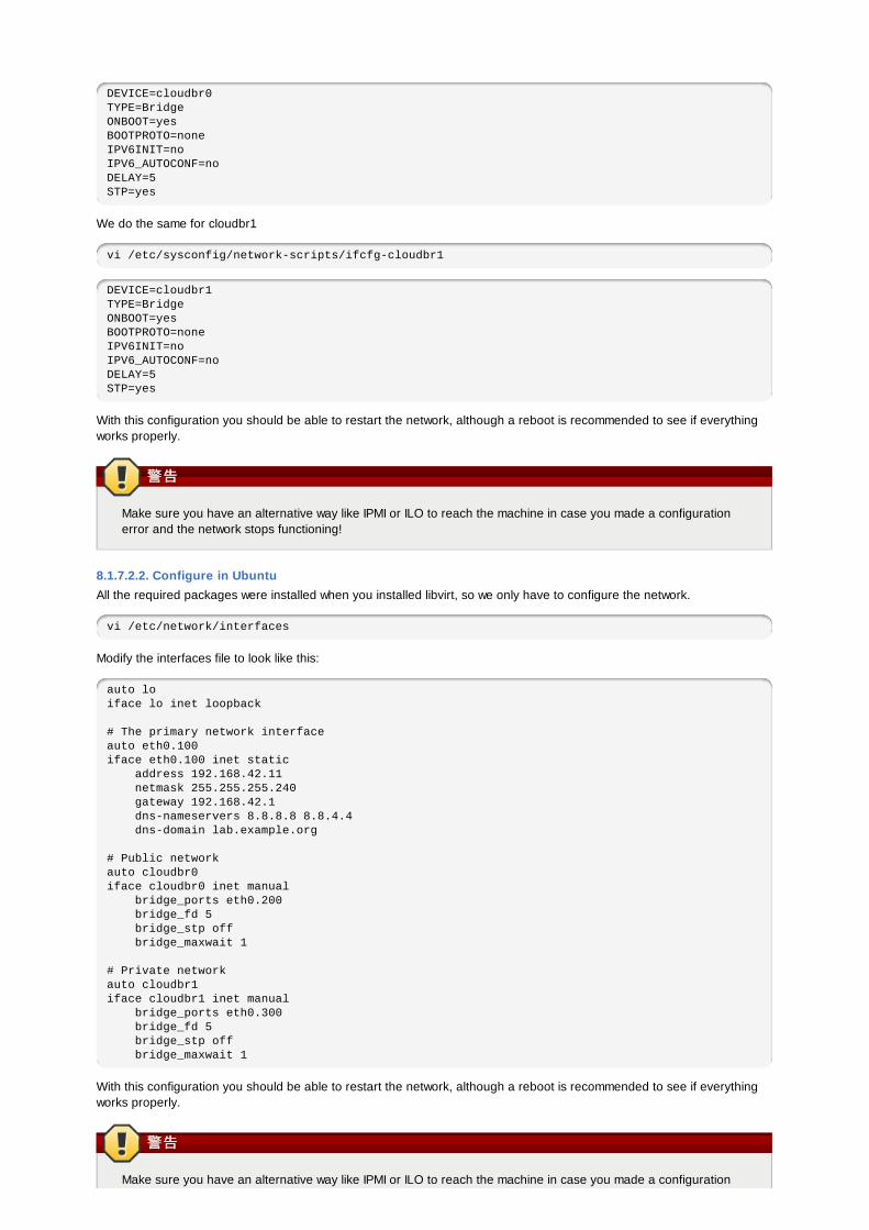
DEVICE=cloudbr0TYPE=BridgeONBOOT=yesBOOTPROTO=noneIPV6INIT=noIPV6_AUTOCONF=noDELAY=5STP=yes
We do the same for cloudbr1
vi /etc/sysconfig/network-scripts/ifcfg-cloudbr1
DEVICE=cloudbr1TYPE=BridgeONBOOT=yesBOOTPROTO=noneIPV6INIT=noIPV6_AUTOCONF=noDELAY=5STP=yes
With this configuration you should be able to restart the network, although a reboot is recommended to see if everythingworks properly.
警告警告
Make sure you have an alternative way like IPMI or ILO to reach the machine in case you made a configurationerror and the network stops functioning!
8.1.7.2.2. Configure in UbuntuAll the required packages were installed when you installed libvirt, so we only have to configure the network.
vi /etc/network/interfaces
Modify the interfaces file to look like this:
auto loiface lo inet loopback
# The primary network interfaceauto eth0.100iface eth0.100 inet static address 192.168.42.11 netmask 255.255.255.240 gateway 192.168.42.1 dns-nameservers 8.8.8.8 8.8.4.4 dns-domain lab.example.org
# Public networkauto cloudbr0iface cloudbr0 inet manual bridge_ports eth0.200 bridge_fd 5 bridge_stp off bridge_maxwait 1
# Private networkauto cloudbr1iface cloudbr1 inet manual bridge_ports eth0.300 bridge_fd 5 bridge_stp off bridge_maxwait 1
With this configuration you should be able to restart the network, although a reboot is recommended to see if everythingworks properly.
警告警告
Make sure you have an alternative way like IPMI or ILO to reach the machine in case you made a configuration
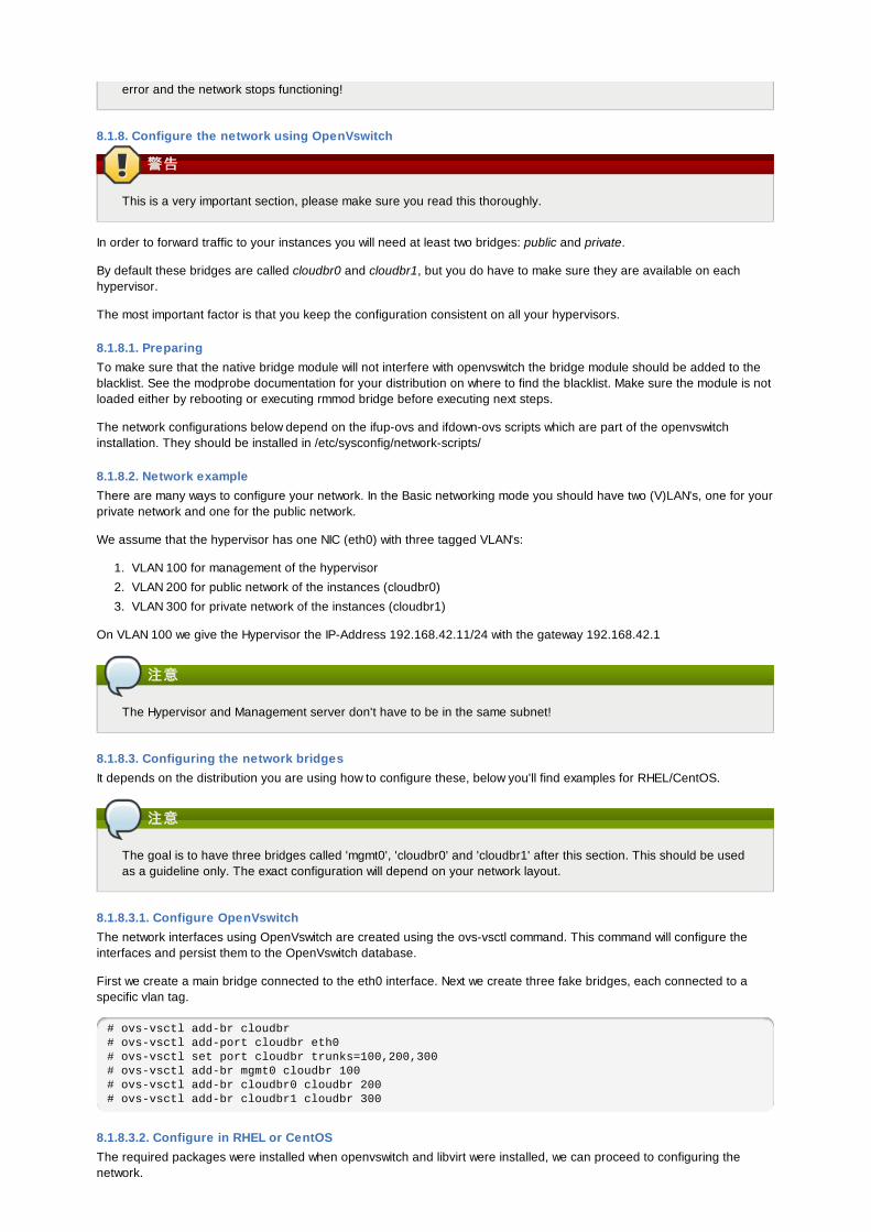
error and the network stops functioning!
8.1.8. Configure the network using OpenVswitch
警告警告
This is a very important section, please make sure you read this thoroughly.
In order to forward traffic to your instances you will need at least two bridges: public and private.
By default these bridges are called cloudbr0 and cloudbr1, but you do have to make sure they are available on eachhypervisor.
The most important factor is that you keep the configuration consistent on all your hypervisors.
8.1.8.1. PreparingTo make sure that the native bridge module will not interfere with openvswitch the bridge module should be added to theblacklist. See the modprobe documentation for your distribution on where to find the blacklist. Make sure the module is notloaded either by rebooting or executing rmmod bridge before executing next steps.
The network configurations below depend on the ifup-ovs and ifdown-ovs scripts which are part of the openvswitchinstallation. They should be installed in /etc/sysconfig/network-scripts/
8.1.8.2. Network exampleThere are many ways to configure your network. In the Basic networking mode you should have two (V)LAN's, one for yourprivate network and one for the public network.
We assume that the hypervisor has one NIC (eth0) with three tagged VLAN's:
1. VLAN 100 for management of the hypervisor
2. VLAN 200 for public network of the instances (cloudbr0)
3. VLAN 300 for private network of the instances (cloudbr1)
On VLAN 100 we give the Hypervisor the IP-Address 192.168.42.11/24 with the gateway 192.168.42.1
注意注意
The Hypervisor and Management server don't have to be in the same subnet!
8.1.8.3. Configuring the network bridgesIt depends on the distribution you are using how to configure these, below you'll find examples for RHEL/CentOS.
注意注意
The goal is to have three bridges called 'mgmt0', 'cloudbr0' and 'cloudbr1' after this section. This should be usedas a guideline only. The exact configuration will depend on your network layout.
8.1.8.3.1. Configure OpenVswitchThe network interfaces using OpenVswitch are created using the ovs-vsctl command. This command will configure theinterfaces and persist them to the OpenVswitch database.
First we create a main bridge connected to the eth0 interface. Next we create three fake bridges, each connected to aspecific vlan tag.
# ovs-vsctl add-br cloudbr# ovs-vsctl add-port cloudbr eth0 # ovs-vsctl set port cloudbr trunks=100,200,300# ovs-vsctl add-br mgmt0 cloudbr 100# ovs-vsctl add-br cloudbr0 cloudbr 200# ovs-vsctl add-br cloudbr1 cloudbr 300
8.1.8.3.2. Configure in RHEL or CentOSThe required packages were installed when openvswitch and libvirt were installed, we can proceed to configuring thenetwork.
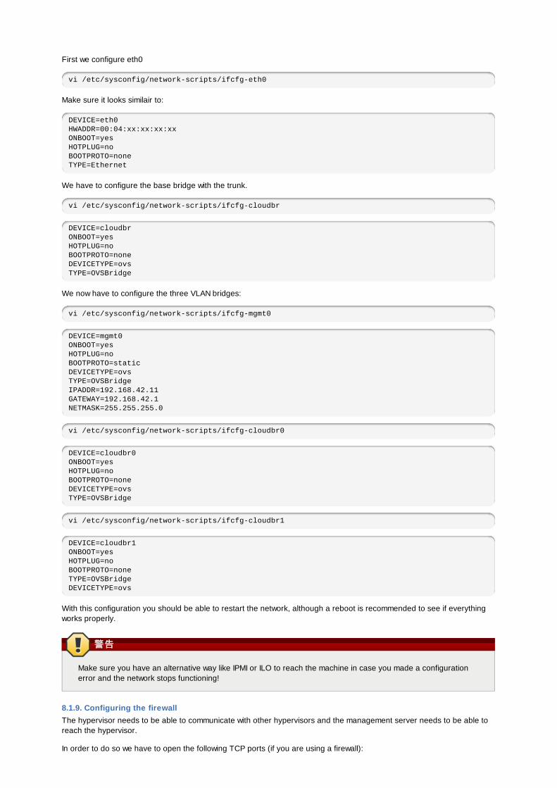
First we configure eth0
vi /etc/sysconfig/network-scripts/ifcfg-eth0
Make sure it looks similair to:
DEVICE=eth0HWADDR=00:04:xx:xx:xx:xxONBOOT=yesHOTPLUG=noBOOTPROTO=noneTYPE=Ethernet
We have to configure the base bridge with the trunk.
vi /etc/sysconfig/network-scripts/ifcfg-cloudbr
DEVICE=cloudbrONBOOT=yesHOTPLUG=noBOOTPROTO=noneDEVICETYPE=ovsTYPE=OVSBridge
We now have to configure the three VLAN bridges:
vi /etc/sysconfig/network-scripts/ifcfg-mgmt0
DEVICE=mgmt0ONBOOT=yesHOTPLUG=noBOOTPROTO=staticDEVICETYPE=ovsTYPE=OVSBridgeIPADDR=192.168.42.11GATEWAY=192.168.42.1NETMASK=255.255.255.0
vi /etc/sysconfig/network-scripts/ifcfg-cloudbr0
DEVICE=cloudbr0ONBOOT=yesHOTPLUG=noBOOTPROTO=noneDEVICETYPE=ovsTYPE=OVSBridge
vi /etc/sysconfig/network-scripts/ifcfg-cloudbr1
DEVICE=cloudbr1ONBOOT=yesHOTPLUG=noBOOTPROTO=noneTYPE=OVSBridgeDEVICETYPE=ovs
With this configuration you should be able to restart the network, although a reboot is recommended to see if everythingworks properly.
警告警告
Make sure you have an alternative way like IPMI or ILO to reach the machine in case you made a configurationerror and the network stops functioning!
8.1.9. Configuring the firewallThe hypervisor needs to be able to communicate with other hypervisors and the management server needs to be able toreach the hypervisor.
In order to do so we have to open the following TCP ports (if you are using a firewall):
1. 22 (SSH)
2. 1798
3. 16509 (libvirt)
4. 5900 - 6100 (VNC consoles)
5. 49152 - 49216 (libvirt live migration)
It depends on the firewall you are using how to open these ports. Below you'll find examples how to open these ports inRHEL/CentOS and Ubuntu.
8.1.9.1. Open ports in RHEL/CentOSRHEL and CentOS use iptables for firewalling the system, you can open extra ports by executing the following iptablecommands:
$ iptables -I INPUT -p tcp -m tcp --dport 22 -j ACCEPT
$ iptables -I INPUT -p tcp -m tcp --dport 1798 -j ACCEPT
$ iptables -I INPUT -p tcp -m tcp --dport 16509 -j ACCEPT
$ iptables -I INPUT -p tcp -m tcp --dport 5900:6100 -j ACCEPT
$ iptables -I INPUT -p tcp -m tcp --dport 49152:49216 -j ACCEPT
These iptable settings are not persistent accross reboots, we have to save them first.
$ iptables-save > /etc/sysconfig/iptables
8.1.9.2. Open ports in UbuntuThe default firewall under Ubuntu is UFW (Uncomplicated FireWall), which is a Python wrapper around iptables.
To open the required ports, execute the following commands:
$ ufw allow proto tcp from any to any port 22
$ ufw allow proto tcp from any to any port 1798
$ ufw allow proto tcp from any to any port 16509
$ ufw allow proto tcp from any to any port 5900:6100
$ ufw allow proto tcp from any to any port 49152:49216
注意注意
By default UFW is not enabled on Ubuntu. Executing these commands with the firewall disabled does not enable thefirewall.
8.1.10. Add the host to CloudStackThe host is now ready to be added to a cluster. This is covered in a later section, see 第 6.6 节 “Adding a Host”. It isrecommended that you continue to read the documentation before adding the host!
8.2. CloudStack中的中的Citrix XenServer安装安装如果你想使用Citrix XenServer作为Hypervisor来运行客户虚拟机, 在你云环境的主机上安装XenServer 6.0或者XenServer6.0.2. 如果是初次安装, 按照下列步骤进行. 如果之前已经安装了XenServer想升级到其它版本, 参见第 8.2.11 节 “升级XenServefr版本”.
8.2.1. XenServer主机的系主机的系统统要求要求
主机必须被验证与下列任一版本兼容. 可参考Citrix硬件兼容性指导: http://hcl.xensource.com
XenServer 5.6 SP2
XenServer 6.0
XenServer 6.0
如果你想重用以前装的某台主机,你必须重新安装Citrix XenServer.
如果你想重用以前装的某台主机,你必须重新安装Citrix XenServer.
Must support HVM (Intel-VT or AMD-V enabled)
Be sure all the hotfixes provided by the hypervisor vendor are applied. Track the release of hypervisor patchesthrough your hypervisor vendor’s support channel, and apply patches as soon as possible after they are released.CloudStack will not track or notify you of required hypervisor patches. It is essential that your hosts are completely upto date with the provided hypervisor patches. The hypervisor vendor is likely to refuse to support any system that is notup to date with patches.
All hosts within a cluster must be homogenous. The CPUs must be of the same type, count, and feature flags.
Must support HVM (Intel-VT or AMD-V enabled in BIOS)
64位 x86CPU(更多的内核性能会更好)
需支持硬件虚拟化4G内存
36G本地硬盘至少1个网卡
分配静态IP地址
部署CloudStack时宿主机务必不能有任何运行中的虚拟机。
警告警告
没有及时更新补丁可能导致数据损坏或虚机丢失.
8.2.2. XenServer安装步安装步骤骤
1. 从https://www.citrix.com/English/ss/downloads/,适合你CloudStack的XenServer的版本 (详见第 8.2.1 节 “XenServer主机的系统要求”).参照Citrix XenServer安装向导来进行安装.
2. 安装完成后, 执行下面几个章节描述的步骤进行配置:
必必须须的的 可可选选的的
第 8.2.3 节 “配置XenServer dom0内存” 第 8.2.7 节 “安装CloudStack XenServer支持包 (CSP)”
第 8.2.4 节 “用户名和密码” 如果不使用NFS, iSCSI或者本地存储, 设置SR请参见第 8.2.8 节 “为XenServer配置主存储”
第 8.2.5 节 “时间同步” 第 8.2.9 节 “XenServer中iSCSI多路径设置(可选)”
第 8.2.6.1 节 “获得并部署许可” 第 8.2.10 节 “XenServer物理网络的设置”
8.2.3. 配置配置XenServer dom0内存内存通过配置XenServer dom0的设置来分配更多的内存给dom0. 这样可以使XenServer能处理更多的虚机. 我们建议给dom0分配2940M内存. 配置说明请参照:http://support.citrix.com/article/CTX126531.这篇文章是针对XenServer5.6的, 但同样适用于XenServer6.0.
8.2.4. 用用户户名和密名和密码码CloudStack一个集群中所有的XenServer必须有相同的用户名和密码.
8.2.5. 时间时间同步同步主机必须设置时间同步服务. 机架上所有的主机必须是相同的时间.
1. 安装NTP.
# yum install ntp
2. 编辑NTP的配置文件来指向你的NTP服务器.
# vi /etc/ntp.conf
在这个文件里添加一行或多行你想使用的服务器地址. 例如:
server 0.xenserver.pool.ntp.orgserver 1.xenserver.pool.ntp.orgserver 2.xenserver.pool.ntp.orgserver 3.xenserver.pool.ntp.org
3. 重启NTP客户端.
# service ntpd restart
4. 确保NTP在系统重新引导的时候可以自动加载.
# chkconfig ntpd on
8.2.6. 许许可可Citrix XenServer免费版本可以使用30天而不需要任何许可. 之后, XenServer需要一个免费的激活来获得许可. 你可以选择现在安装一个许可或忽略它. 如果你现在忽略这个步骤, 你可以在将来激活时安装许可到XenServer上.
8.2.6.1. 获获得并部署得并部署许许可可如果你选择现在安装许可, 你需要通过XenCenter来获得许可并激活.
1. 在XenCenter里, 点击>许可管理.
2. 选择你的XenServer并选择激活免费的XenServer.
3. 请求一个许可.
你可以通过XenCenter或xe命令行工具来安装你的许可.
8.2.7. 安装安装CloudStack XenServer支持包支持包 (CSP)(可选)
要在XenServer上使用安全组, 动态负载均衡和弹性IP, 下载并安装CloudStack XenServer支持包(CSP). 安装XenServer完成后, 在每台主机上执行下列额外的步骤.
1. 从下列链接地址下载CSP软件到XenServer主机链接地址:For XenServer 6.0.2:
http://download.cloud.com/releases/3.0.1/XS-6.0.2/xenserver-cloud-supp.tgz
For XenServer 5.6 SP2:
http://download.cloud.com/releases/2.2.0/xenserver-cloud-supp.tgz
For XenServer 6.0:
http://download.cloud.com/releases/3.0/xenserver-cloud-supp.tgz
2. 解压文件:
# tar xf xenserver-cloud-supp.tgz
3. 执行下列脚本:
# xe-install-supplemental-pack xenserver-cloud-supp.iso
4. 如果XenServer主机所在的zone使用的是基本网络模式 ,禁用 Open vSwitch (OVS):
# xe-switch-network-backend bridge
执行完成后重启主机。
XenServer 主机目前可以加入到 CloudStack.
8.2.8. 为为XenServer配置主存配置主存储储CloudStack 默认支持 NFS,iSCSI 和本地存储 。如果您 使用任意其中一种存储, 无需再为XenServer创建存储 仓库 ("SR").
如果你想通过其它的技术来连接你的存储, 比如光纤通道, 你必须自己设置SR. 你可以通过下面的步骤来完成这样的设置. 如果你的主机在XenServer的资源池里, 对了就在Master节点上执行这些步骤. 如果你只是在一个不属于任何集群的单一节点上工作, 那就在这台XenServer上执行这些步骤.
1. 把光纤通过光纤通道连接到集群中的所有主机上同时也连接到光纤存储设备上.
2. 重新扫描SCSI总线. 可以通过下面的命令或者通过XenCenter来执行HBA的重新扫描.
# scsi-rescan
3. Repeat step 2 on every host.
4. 检查并确保你能看到新的SCSI磁盘.
# ls /dev/disk/by-id/scsi-360a98000503365344e6f6177615a516b -l
输出应该像这样, 虽然指定的文件名不同 (scsi-<scsiID>):
lrwxrwxrwx 1 root root 9 Mar 16 13:47/dev/disk/by-id/scsi-360a98000503365344e6f6177615a516b -> ../../sdc
5. Repeat step 4 on every host.
6. 在存储服务器上, 运行这个命令来为新的SR获得唯一标识.
6. 在存储服务器上, 运行这个命令来为新的SR获得唯一标识.
# uuidgen
输出应该像这样, 虽然指定的ID不同:
e6849e96-86c3-4f2c-8fcc-350cc711be3d
7. 创建光纤通道SR. name-label使用你刚刚生成的UUID.
# xe sr-create type=lvmohba shared=truedevice-config:SCSIid=360a98000503365344e6f6177615a516bname-label="e6849e96-86c3-4f2c-8fcc-350cc711be3d"
这个命令SR的UUID, 像下面的例子(你的ID是不同的):
7a143820-e893-6c6a-236e-472da6ee66bf
8. 为了给SR创建通俗易懂的描述, uuid参数使用使用前面命令返回的SR ID. 在name-description参数里,设置任何你自己喜欢的描述.
# xe sr-param-set uuid=7a143820-e893-6c6a-236e-472da6ee66bf name-description="Fiber Channel storage repository"
你要记住这些值以便稍后将此存储添加到CloudStack中(参照 第 6.7 节 “æ·»å 主å å ¨”). 在添加主存储的对话框中, 在协议栏里选择PreSetup. 在SR name-label栏中, 你将要输入你早先设置的name-label(本例是e6849e96-86c3-4f2c-8fcc-350cc711be3d).
9. (可选)如果你想在FC-SAN中启用多路径I/O, 请参照SAN销售商提供的相关文档.
8.2.9. XenServer中中 iSCSI多路径多路径设设置置 (可可选选 )当在一个XenServer上设置存储仓库里,你可以启用多路径I/O, 这可以通过冗余的物理链路在服务器与SAN设备之间提供更好的连接可靠性. 为了启用多路径, 要根据Citrix文档描述的步骤并选择Citrix服务器支持的SAN解决方案. 下面的链接提供了一个起点:
http://support.citrix.com/article/CTX118791
http://support.citrix.com/article/CTX125403
你同时可以听取你的SAN销售商的建议来设置Citrix仓库的多路径.
你要记住这些值以便稍后将此存储添加到CloudStack中(参照 第 6.7 节 “æ·»å 主å å ¨”). 在添加主存储的对话框中, 在协议栏里选择PreSetup. 在SR name-label栏中, 你将要输入相同的名字来创建SR.
如果你遇到任何困难, 请从你的SAN供货商团队那儿获得支持. 如果仍然无法解决你的问题, 请参照联系技术支持.
8.2.10. XenServer物理网物理网络络的的设设置置XenServer安装完成后, 你需要对网络做一些额外的设置. 安装到这个时候, 你应该对主机上的网卡及每个网络携带的流量有一个整体规划. 网卡必须适当的连接网线来满足你的规划.
如果你计划使用网卡绑定, 那一个集群里所有的主机的网卡必须采用完成相同的网络接线. 例如, 如果eth0在集群中一个主机的私有绑定上, 那集群中所有的主机的eth0也必须在私有绑定上.
分配给管理网络的IP必须是静态IP. 这可以通过设置主机自身或通过静态DHCP来分配IP.
CloudStack在XenServer上使用不同的网卡或网卡绑定来配置各种网络流量类型. 你可以通过XenServer的网络名称标签来进行控制同时提供给管理服务器. 名称标签设置在物理网卡或绑定的网卡上并在CloudStack里配置. 在一些简单的使用场景中名称标签不是必须要设置的.
8.2.10.1. XenServer中配置公共网中配置公共网络络使用一个使用一个专专有网卡有网卡 (可可选选 )CloudStack 支持使用第二块网卡(或者一对绑定的网卡,详见第 8.2.10.4 节 “网卡绑定(可选)”)用作公共网络. 如果未使用绑定, 公共网络可以是任何网卡并且可以是集群中主机的不同网卡. 比如, 公共网络可以是节点A的eth0和节点B的eth1. 尽管如此,公共网络中 XenServer的名称标签在所有的主机上必须一致.下列的例子设置网络标签"cloud-public". 管理服务器安装并运行后,你必须选择网络标签的名字来进行配置(比如: "cloud-public"); 这一部分在 第 4.5 节 “管理服务器安装”中讨论.
如果你用两个网卡绑定在一起创建公共网络, 参照 第 8.2.10.4 节 “网卡绑定(可选)”.
如果你正在使用单独的网卡专门提供公共网络访问, 在添加主机到CloudStack之前, 在每台要添加的主机上执行下列步骤.
1. 运行 xe network-list并找出公共网络. 这通常是public被附加到网卡上. 一旦你找到这个网络就记下它的UUID. 这里称其为<UUID-Public>.
2. 运行如下命令.
# xe network-param-set name-label=cloud-public uuid=<UUID-Public>
8.2.10.2. XenServer配置多个来配置多个来宾宾网网络络 (可可选选 )CloudStack 支持在XenServer Hypervisor上使用多个来宾网络.每一个网络在XenServer里都会分配一个name-label. 例如, 你可能有两个网络, 它们的标签分别是 "cloud-guest" 和 "cloud-guest2". 当管理服务器安装并运行后, 你必须添加网络并使用这些标签以便CloudStack能感知网络.
在添加主机到CloudStack之前执行下列步骤:
1. 运行 xe network-list并找出一个来宾网络. 一旦找到这个网络就记录它的UUID. 称其为<UUID-Guest>.
2. 运行下面的命令, 替换你自己的name-label和UUID的值.
# xe network-param-set name-label=<cloud-guestN> uuid=<UUID-Guest>
3. 每一个额外的来宾网络都重复这些步骤, 记住每次要使用不同的name-lable和UUID.
8.2.10.3. XenServer设设置置单单独的存独的存储储网网络络 (可可选选 )可以选择设置一个单独的存储网络(separate storage network)。这应该在实施如下的绑定步骤之前,首先在主机上完成。使用1到2个网卡可以完成此步骤。上述给出了两块网卡绑定的示例。
给存储网络一个不同于其他网络的name-label。
为了让单独的存储网络工作正常,主机上对应存储网络的接口必须是能ping通主存储设备IP地址的唯一接口。例如,如果eth0是内网网卡,ping -I eth0 primary storage IP 必须失败。在所有部署的主机上,二级存储设备必须可通过内网网卡或对应的绑定网卡ping通。如果二级存储设备在存储网络中,则通过存储网络对应网卡或绑定网卡也必须可以ping通。
也可以设置两个单独的存储网络。例如,如果想实施iSCSI多路径,则用两块未绑定的网卡用于配置路径。每一个网络都需要一个独立的name-label.
如果未进行绑定,则管理员必须在所有的主机上设置和命名存储网络。
以下是设置eth5接入位于172.16.0.0/24的存储网络的示例。
# xe pif-list host-name-label='hostname' device=eth5uuid(RO): ab0d3dd4-5744-8fae-9693-a022c7a3471ddevice ( RO): eth5#xe pif-reconfigure-ip DNS=172.16.3.3 gateway=172.16.0.1 IP=172.16.0.55 mode=static netmask=255.255.255.0 uuid=ab0d3dd4-5744-8fae-9693-a022c7a3471d
8.2.10.4. 网卡网卡绑绑定(可定(可选选))XenServer支持Source Level Balancing (SLB) NIC绑定。两块网卡可被绑定在一起承载外网、内网通信。单独的存储网络同样可能。以下是一些支持示例的配置:
2 NICs on private, 2 NICs on public, 2 NICs on storage
2 NICs on private, 1 NIC on public, storage uses management network
2 NICs on private, 2 NICs on public, storage uses management network
1 NIC for private, public, and storage
所有的NIC绑定都是可选的。
XenServer希望一个集群中所有的节点都拥有相同的网络布线,以及相同的绑定。在一次安装中,master将是添加至集群的第一台主机,而slave host将是随后添加至集群的主机。Master上的网卡绑定设置了随后添加至集群的主机的样本。在master和slave上设置网卡绑定的步骤不同,如下所示。其重要含义包括:
必须在添加至集群的第一台主机上设置网卡绑定。然后必须使用如下的xe命令,在第二台和随后添加至集群的主机上建立网卡绑定。一个集群中的Slave hosts必须与master进行完全相同的布线。例如,如果eth0在集群中的一个主机上的一个内网绑定中,则eth0必须在集群中的所有主机上内网绑定中。
8.2.10.4.1. 内网内网绑绑定定管理员必须在添加主机至CloudStack之前,绑定内网网卡
8.2.10.4.2. 在集群的第一台主机上在集群的第一台主机上创创建内网网卡建内网网卡绑绑定定使用下述步骤来在XenServer上创建网卡绑定。这些步骤应只运行在集群的第一台主机上。本示例以两块物理NIC(eth0和eth1)的绑定创建了cloud-private的网络。
1. 找到想要绑定在一起的物理NIC。
# xe pif-list host-name-label='hostname' device=eth0# xe pif-list host-name-label='hostname' device=eth1
这些命令显示了eth0、eth1 NIC和他们的UUID。可根据你的选择替换ethX 设备。将上述命令返回的UUID称为slave1-
这些命令显示了eth0、eth1 NIC和他们的UUID。可根据你的选择替换ethX 设备。将上述命令返回的UUID称为slave1-UUID和slave2-UUID。
2. 为网卡绑定创建一个新的网络,名称为“cloud-private”。
重要:本标签很重要,因为CloudStack在根据你配置的名称来查找网络。必须对云中所有主机的内网使用同样的name-label。
# xe network-create name-label=cloud-private# xe bond-create network-uuid=[uuid of cloud-private created above]pif-uuids=[slave1-uuid],[slave2-uuid]
现在有了一个可被CloudStack识别为内网的bonded pair。
8.2.10.4.3. 外网外网绑绑定定绑定可以在一个单独的外网上执行。管理员可以将外网网卡绑定,并且与内网区分。
8.2.10.4.4. 在集群的第一台主机上在集群的第一台主机上创创建外网建外网绑绑定定以下步骤应运行在集群的第一台主机上。本示例以两块物理网卡(eth2和eth3)的绑定创建了cloud-public网络。
1. 找到想要绑定在一起的物理NIC。
#xe pif-list host-name-label='hostname' device=eth2# xe pif-list host-name-label='hostname' device=eth3
这些命令显示了eth2、eth3 NIC和他们的UUID。可根据你的选择替换ethX 设备。将上述命令返回的UUID称为slave1-UUID和slave2-UUID。
2. 为该绑定创建一个新的网络。例如,一个名为“cloud-public”的新网络。重要:本标签很重要,因为CloudStack在根据你配置的名称来查找网络。必须对云中所有主机的公共网络使用同样的name-label。
# xe network-create name-label=cloud-public# xe bond-create network-uuid=[uuid of cloud-public created above]pif-uuids=[slave1-uuid],[slave2-uuid]
现在有了一个可被CloudStack识别为公共网络的bonded pair。
8.2.10.4.5. 添加更多主机至集群添加更多主机至集群
在master主机添加了(任何)绑定网卡的基础上,可以添加额外的slave 主机。对所有添加至集群的其他主机执行本步骤。这会使主机加入单一XenServer池中的master中。
# xe pool-join master-address=[master IP] master-username=rootmaster-password=[your password]
8.2.10.4.6. 完成集群内的完成集群内的绑绑定定设设置置在所有主机添加至资源池的情况下,运行cloud-setup-bond脚本。此脚本将会完成配置并且设立集群里所有主机的网卡绑定。
1. Copy the script from the Management Server in /usr/lib64/cloud/common/scripts/vm/hypervisor/xenserver/cloud-setup-bonding.sh to the master host and ensure it is executable.
2. 运行脚本。
# ./cloud-setup-bonding.sh
现在网卡绑定已经设立完毕,并在集群范围内得以恰当配置。
8.2.11. 升升级级XenServefr版本版本这个章节介绍如何升级CloudStack主机中的XenServer.实际升级的操作在XenServer的文档里有详细描述, 但是有一些额外的步骤你必须在升级前后执行.
注意注意
确保硬件获得新版本XenServer的认证.
要升级XenServer:
1. 升级数据库. 在管理服务器节点上:
a. 备份数据库:
# mysqldump --user=root --databases cloud > cloud.backup.sql

# mysqldump --user=root --databases cloud > cloud.backup.sql# mysqldump --user=root --databases cloud_usage > cloud_usage.backup.sql
b. 你可能要更改运行在升级后主机上的虚机的操作系统类型设置.
如果你从XenServer 5.6 GA升级到XenServer 5.6 SP2, 更改以下所有虚机操作系统类型到Other Linux(32-bit):CentOS 5.5 (32-bit), Oracle Enterprise Linux 5.5 (32-bit), or Red Hat Enterprise Linux 5.5 (32-bit). 同样这些虚机的64-bit版本操作系统类型要改成Other Linux(64-bit).
如果你要从 XenServer 5.6 SP2 升级到 XenServer 6.0.2, 更改以下所有虚机操作系统类型到Other Linux(32-bit):CentOS 5.6 (32-bit), CentOS 5.7 (32-bit), Oracle Enterprise Linux 5.6 (32-bit), Oracle Enterprise Linux5.7 (32-bit), Red Hat Enterprise Linux 5.6 (32-bit) , or Red Hat Enterprise Linux 5.7 (32-bit) . 32-bit). 同样这些虚机的64-bit版本操作系统类型要改成Other Linux(64-bit).
如果你要从XenServer 5.6 升级到XenServer 6.0.2, 请做上述所有的操作.
c. 重启管理服务和Usage服务. 你只需要为所有的集群做一次这样的操作.
# service cloud-management start# service cloud-usage start
2. 从CloudStack断开XenServer集群.
a. 用admin账号登录CloudStack.
b. 导航到XenServer集群, 点击操作 – 取消管理
c. 查看集群状态直到显示未受管理.
3. 登录到集群中任一台主机, 并运行下面的命令清除VLAN信息:
# . /opt/xensource/bin/cloud-clean-vlan.sh
4. 在这台登录的主机上, 运行下面的升级准备脚本:
# /opt/xensource/bin/cloud-prepare-upgrade.sh
问题解答: 如果你看到错误"can't eject CD", 请登录到虚拟机里卸载CD然后重新运行上述命令.
5. 在集群中所有的主机上升级XenServer软件. 首先升级Master节点.
a. 将这台主机上所有的虚拟机动态迁移到其它主机上. 动态迁移的指令请参照管理员向导.
问题解答: 当你迁移虚拟机时可能遇到下面的错误:
[root@xenserver-qa-2-49-4 ~]# xe vm-migrate live=true host=xenserver-qa-2-49-5 vm=i-2-8-VMYou attempted an operation on a VM which requires PV drivers to be installed but the drivers were not detected.vm: b6cf79c8-02ee-050b-922f-49583d9f1a14 (i-2-8-VM)
要解决这个问题, 需运行下面命令:
# /opt/xensource/bin/make_migratable.sh b6cf79c8-02ee-050b-922f-49583d9f1a14
b. 重启这台主机.
c. 要升级到更新版本的XenServer. 请按照XenServer文档步骤进行.
d. 升级完成后, 将下列文件从管理服务器拷贝到这台主机, 请按照下面给出的文件路径进行拷贝:
拷拷贝贝管理服管理服务务器的文件器的文件 ... ...到到XenServer主机的路径主机的路径
/usr/lib64/cloud/common/scripts/vm/hypervisor/xenserver/xenserver60/NFSSR.py
/opt/xensource/sm/NFSSR.py
/usr/lib64/cloud/common/scripts/vm/hypervisor/xenserver/setupxenserver.sh
/opt/xensource/bin/setupxenserver.sh
/usr/lib64/cloud/common/scripts/vm/hypervisor/xenserver/make_migratable.sh
/opt/xensource/bin/make_migratable.sh
/usr/lib64/cloud/common/scripts/vm/hypervisor/xenserver/cloud-clean-vlan.sh
/opt/xensource/bin/cloud-clean-vlan.sh
e. 执行下列脚本:
# /opt/xensource/bin/setupxenserver.sh
问题解答: 如果你看到下面的错误信息, 可以简单的忽略它.
mv: cannot stat `/etc/cron.daily/logrotate': No such file or directory
f. 连接存储库(物理块设备)到XenServer主机:
# for pbd in `xe pbd-list currently-attached=false| grep ^uuid | awk '{print $NF}'`; do xe pbd-plug uuid=$pbd ; done
注意: 如果你添加一台主机到XenServer资源池中, 你需要将其上的所有虚拟机迁移到其它主机上, 并且将这台主机从XenServer资源池中移出.
6. 重复这些步骤来升级每一台主机, 以确保集群中所有的主机都是相同版本的XenServer.
7. 在XenServer集群中一台主机上运行下面的命令来清除主机标签:
# for host in $(xe host-list | grep ^uuid | awk '{print $NF}') ; do xe host-param-clear uuid=$host param-name=tags; done;
注意注意
当拷贝粘贴一条命令, 确保在运行前粘贴的命令在一行上. 一些文档查看器可能会在拷贝时引入不希望的换行符.
8. 重新连接XenServer集群到CloudStack.
a. 用admin账号登录CloudStack.
b. 导航到XenServer集群, 并点击操作--管理.
c. 查看状态以确保所有的主机都恢复正常.
9. 当所有的主机都是运行状态后, 在集群中的一台主机上运行下列的命令:
# /opt/xensource/bin/cloud-clean-vlan.sh
8.3. VMware vSphere 安装和配置安装和配置If you want to use the VMware vSphere hypervisor to run guest virtual machines, install vSphere on the host(s) in yourcloud.
8.3.1. System Requirements for vSphere Hosts
8.3.1.1. Software requirements:
vSphere and vCenter, both version 4.1 or 5.0.
vSphere Standard is recommended. Note however that customers need to consider the CPU constraints in place withvSphere licensing. See http://www.vmware.com/files/pdf/vsphere_pricing.pdf and discuss with your VMware salesrepresentative.
vCenter Server Standard is recommended.
Be sure all the hotfixes provided by the hypervisor vendor are applied. Track the release of hypervisor patchesthrough your hypervisor vendor's support channel, and apply patches as soon as possible after they are released.CloudStack will not track or notify you of required hypervisor patches. It is essential that your hosts are completely upto date with the provided hypervisor patches. The hypervisor vendor is likely to refuse to support any system that is notup to date with patches.
Apply All Necessary Hotfixes
缺乏最新补丁更新可能会导致数据和虚拟机丢失。
8.3.1.2. Hardware requirements:
The host must be certified as compatible with vSphere. See the VMware Hardware Compatibility Guide athttp://www.vmware.com/resources/compatibility/search.php.
All hosts must be 64-bit and must support HVM (Intel-VT or AMD-V enabled).
在一个集群中所有的主机必须是同构的. 这表示它们的CPU必须是相同的型号,有相同的数量和相同的功能标志.
64位x86架构CPU(多个核心性能更好)
需求硬件虚拟化支持4GB内存
36GB的本地磁盘至少一块网卡静态分配的IP地址
8.3.1.3. vCenter Server requirements:
Processor - 2 CPUs 2.0GHz or higher Intel or AMD x86 processors. Processor requirements may be higher if thedatabase runs on the same machine.
Memory - 3GB RAM. RAM requirements may be higher if your database runs on the same machine.
Memory - 3GB RAM. RAM requirements may be higher if your database runs on the same machine.
Disk storage - 2GB. Disk requirements may be higher if your database runs on the same machine.
Microsoft SQL Server 2005 Express disk requirements. The bundled database requires up to 2GB free disk space todecompress the installation archive.
Networking - 1Gbit or 10Gbit.
For more information, see "vCenter Server and the vSphere Client Hardware Requirements" athttp://pubs.vmware.com/vsp40/wwhelp/wwhimpl/js/html/wwhelp.htm#href=install/c_vc_hw.html.
8.3.1.4. Other requirements:
VMware vCenter Standard Edition 4.1 or 5.0 must be installed and available to manage the vSphere hosts.
vCenter must be configured to use the standard port 443 so that it can communicate with the CloudStack ManagementServer.
You must re-install VMware ESXi if you are going to re-use a host from a previous install.
CloudStack requires VMware vSphere 4.1 or 5.0. VMware vSphere 4.0 is not supported.
All hosts must be 64-bit and must support HVM (Intel-VT or AMD-V enabled). All hosts within a cluster must behomogenous. That means the CPUs must be of the same type, count, and feature flags.
The CloudStack management network must not be configured as a separate virtual network. The CloudStackmanagement network is the same as the vCenter management network, and will inherit its configuration. See第 8.3.5.2 节 “Configure vCenter Management Network”.
CloudStack requires ESXi. ESX is not supported.
All resources used for CloudStack must be used for CloudStack only. CloudStack cannot share instance of ESXi orstorage with other management consoles. Do not share the same storage volumes that will be used by CloudStack witha different set of ESXi servers that are not managed by CloudStack.
Put all target ESXi hypervisors in a cluster in a separate Datacenter in vCenter.
The cluster that will be managed by CloudStack should not contain any VMs. Do not run the management server,vCenter or any other VMs on the cluster that is designated for CloudStack use. Create a separate cluster for use ofCloudStack and make sure that they are no VMs in this cluster.
All the required VLANS must be trunked into all network switches that are connected to the ESXi hypervisor hosts.These would include the VLANS for Management, Storage, vMotion, and guest VLANs. The guest VLAN (used inAdvanced Networking; see Network Setup) is a contiguous range of VLANs that will be managed by CloudStack.
8.3.2. Preparation Checklist for VMwareFor a smoother installation, gather the following information before you start:
Information listed in 第 8.3.2.1 节 “vCenter Checklist”
Information listed in 第 8.3.2.2 节 “Networking Checklist for VMware”
8.3.2.1. vCenter ChecklistYou will need the following information about vCenter.
vCenter Requirement å ¼ Notes
vCenter User This user must have admin privileges.
vCenter User Password Password for the above user.
vCenter Datacenter Name Name of the datacenter.
vCenter Cluster Name Name of the cluster.
8.3.2.2. Networking Checklist for VMwareYou will need the following information about VLAN.
VLAN Information å ¼ Notes
ESXi VLAN VLAN on which all your ESXihypervisors reside.
ESXI VLAN IP Address IP Address Range in the ESXi VLAN.One address per Virtual Router isused from this range.
ESXi VLAN IP Gateway
ESXi VLAN Netmask
Management Server VLAN VLAN on which the CloudStackManagement server is installed.
Public VLAN VLAN for the Public Network.
Public VLAN Gateway
Public VLAN Netmask

Public VLAN Netmask
Public VLAN IP Address Range Range of Public IP Addressesavailable for CloudStack use. Theseaddresses will be used for virtualrouter on CloudStack to route privatetraffic to external networks.
VLAN Range for Customer use A contiguous range of non-routableVLANs. One VLAN will be assigned foreach customer.
8.3.3. vSphere Installation Steps
1. If you haven't already, you'll need to download and purchase vSphere from the VMware Website(https://www.vmware.com/tryvmware/index.php?p=vmware-vsphere&lp=1) and install it by following the VMwarevSphere Installation Guide.
2. Following installation, perform the following configuration, which are described in the next few sections:
必必须须的的 可可选选的的
ESXi host setup NIC bonding
Configure host physical networking, virtual switch,vCenter Management Network, and extended portrange
Multipath storage
Prepare storage for iSCSI
Configure clusters in vCenter and add hosts to them, oradd hosts without clusters to vCenter
8.3.4. ESXi Host setupAll ESXi hosts should enable CPU hardware virtualization support in BIOS. Please note hardware virtualization support isnot enabled by default on most servers.
8.3.5. Physical Host NetworkingYou should have a plan for cabling the vSphere hosts. Proper network configuration is required before adding a vSpherehost to CloudStack. To configure an ESXi host, you can use vClient to add it as standalone host to vCenter first. Once yousee the host appearing in the vCenter inventory tree, click the host node in the inventory tree, and navigate to theConfiguration tab.
In the host configuration tab, click the "Hardware/Networking" link to bring up the networking configuration page as above.
8.3.5.1. Configure Virtual SwitchA default virtual switch vSwitch0 is created. CloudStack requires all ESXi hosts in the cloud to use the same set of virtual
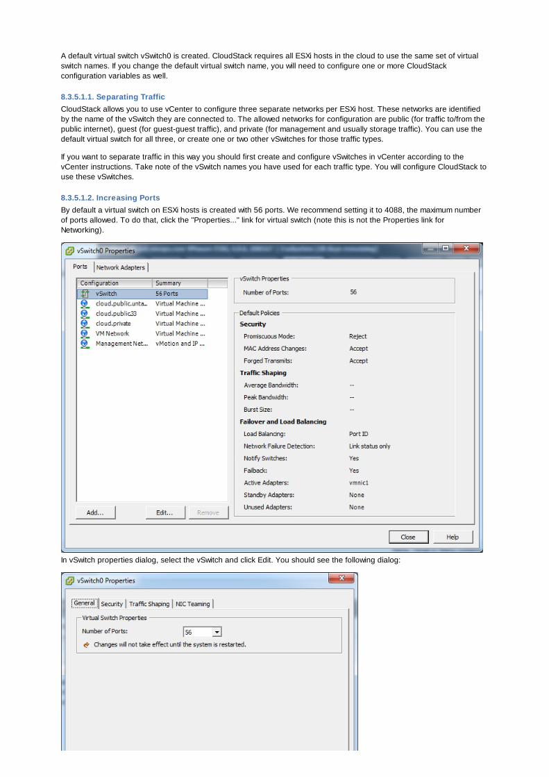
A default virtual switch vSwitch0 is created. CloudStack requires all ESXi hosts in the cloud to use the same set of virtualswitch names. If you change the default virtual switch name, you will need to configure one or more CloudStackconfiguration variables as well.
8.3.5.1.1. Separating TrafficCloudStack allows you to use vCenter to configure three separate networks per ESXi host. These networks are identifiedby the name of the vSwitch they are connected to. The allowed networks for configuration are public (for traffic to/from thepublic internet), guest (for guest-guest traffic), and private (for management and usually storage traffic). You can use thedefault virtual switch for all three, or create one or two other vSwitches for those traffic types.
If you want to separate traffic in this way you should first create and configure vSwitches in vCenter according to thevCenter instructions. Take note of the vSwitch names you have used for each traffic type. You will configure CloudStack touse these vSwitches.
8.3.5.1.2. Increasing PortsBy default a virtual switch on ESXi hosts is created with 56 ports. We recommend setting it to 4088, the maximum numberof ports allowed. To do that, click the "Properties..." link for virtual switch (note this is not the Properties link forNetworking).
In vSwitch properties dialog, select the vSwitch and click Edit. You should see the following dialog:
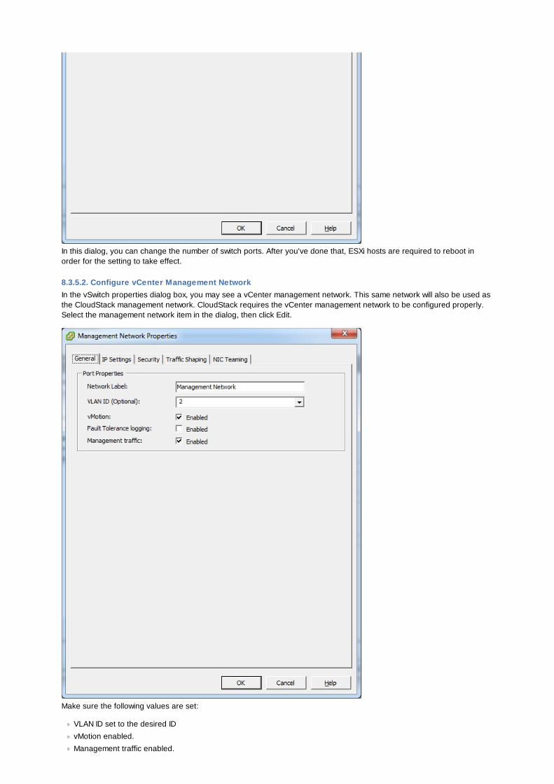
In this dialog, you can change the number of switch ports. After you've done that, ESXi hosts are required to reboot inorder for the setting to take effect.
8.3.5.2. Configure vCenter Management NetworkIn the vSwitch properties dialog box, you may see a vCenter management network. This same network will also be used asthe CloudStack management network. CloudStack requires the vCenter management network to be configured properly.Select the management network item in the dialog, then click Edit.
Make sure the following values are set:
VLAN ID set to the desired ID
vMotion enabled.
Management traffic enabled.
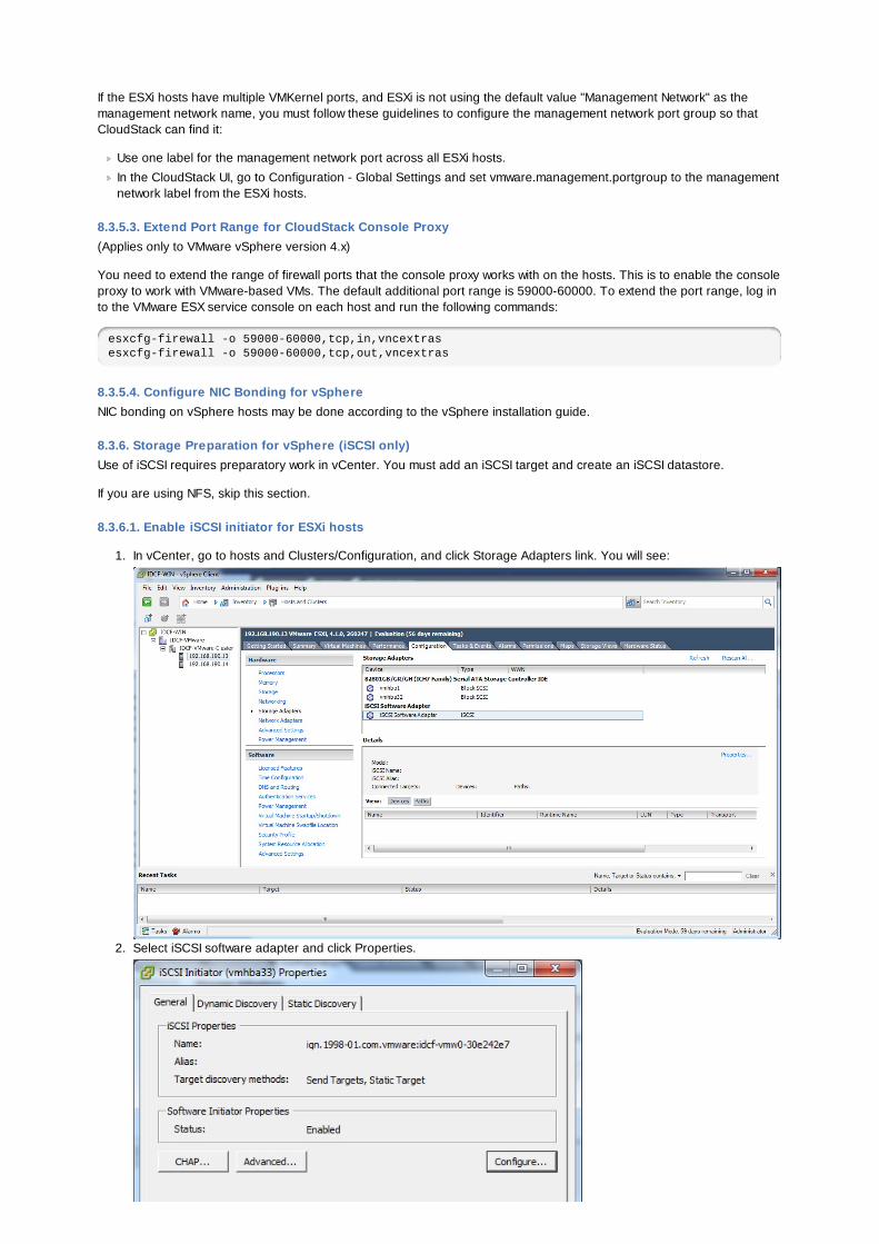
If the ESXi hosts have multiple VMKernel ports, and ESXi is not using the default value "Management Network" as themanagement network name, you must follow these guidelines to configure the management network port group so thatCloudStack can find it:
Use one label for the management network port across all ESXi hosts.
In the CloudStack UI, go to Configuration - Global Settings and set vmware.management.portgroup to the managementnetwork label from the ESXi hosts.
8.3.5.3. Extend Port Range for CloudStack Console Proxy(Applies only to VMware vSphere version 4.x)
You need to extend the range of firewall ports that the console proxy works with on the hosts. This is to enable the consoleproxy to work with VMware-based VMs. The default additional port range is 59000-60000. To extend the port range, log into the VMware ESX service console on each host and run the following commands:
esxcfg-firewall -o 59000-60000,tcp,in,vncextrasesxcfg-firewall -o 59000-60000,tcp,out,vncextras
8.3.5.4. Configure NIC Bonding for vSphereNIC bonding on vSphere hosts may be done according to the vSphere installation guide.
8.3.6. Storage Preparation for vSphere (iSCSI only)Use of iSCSI requires preparatory work in vCenter. You must add an iSCSI target and create an iSCSI datastore.
If you are using NFS, skip this section.
8.3.6.1. Enable iSCSI initiator for ESXi hosts
1. In vCenter, go to hosts and Clusters/Configuration, and click Storage Adapters link. You will see:
2. Select iSCSI software adapter and click Properties.
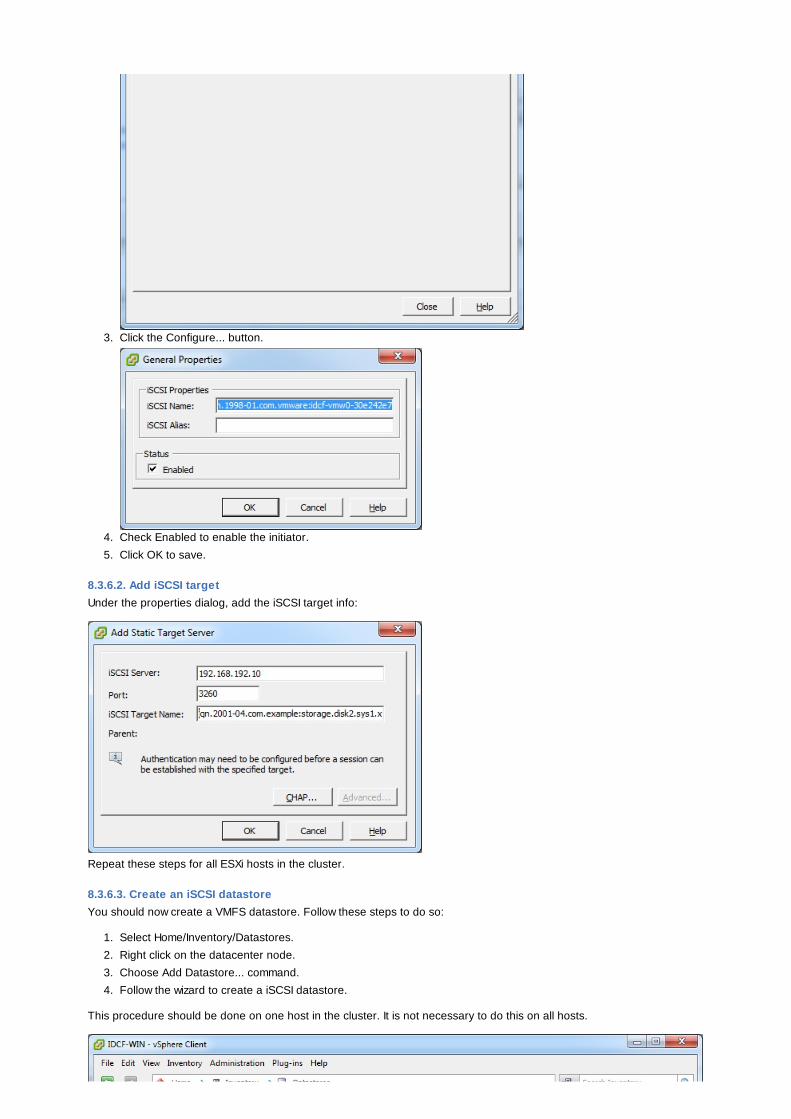
3. Click the Configure... button.
4. Check Enabled to enable the initiator.
5. Click OK to save.
8.3.6.2. Add iSCSI targetUnder the properties dialog, add the iSCSI target info:
Repeat these steps for all ESXi hosts in the cluster.
8.3.6.3. Create an iSCSI datastoreYou should now create a VMFS datastore. Follow these steps to do so:
1. Select Home/Inventory/Datastores.
2. Right click on the datacenter node.
3. Choose Add Datastore... command.
4. Follow the wizard to create a iSCSI datastore.
This procedure should be done on one host in the cluster. It is not necessary to do this on all hosts.
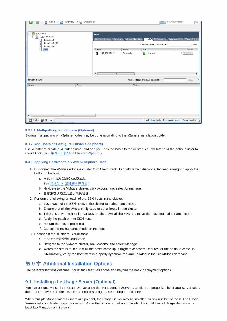
8.3.6.4. Multipathing for vSphere (Optional)Storage multipathing on vSphere nodes may be done according to the vSphere installation guide.
8.3.7. Add Hosts or Configure Clusters (vSphere)Use vCenter to create a vCenter cluster and add your desired hosts to the cluster. You will later add the entire cluster toCloudStack. (see 第 6.5.2 节 “Add Cluster: vSphere”).
8.3.8. Applying Hotfixes to a VMware vSphere Host
1. Disconnect the VMware vSphere cluster from CloudStack. It should remain disconnected long enough to apply thehotfix on the host.
a. 用admin账号登录CloudStack.
See 第 5.1 节 “登陆到用户界面”.
b. Navigate to the VMware cluster, click Actions, and select Unmanage.
c. 查看集群状态直到显示未受管理.
2. Perform the following on each of the ESXi hosts in the cluster:
a. Move each of the ESXi hosts in the cluster to maintenance mode.
b. Ensure that all the VMs are migrated to other hosts in that cluster.
c. If there is only one host in that cluster, shutdown all the VMs and move the host into maintenance mode.
d. Apply the patch on the ESXi host.
e. Restart the host if prompted.
f. Cancel the maintenance mode on the host.
3. Reconnect the cluster to CloudStack:
a. 用admin账号登录CloudStack.
b. Navigate to the VMware cluster, click Actions, and select Manage.
c. Watch the status to see that all the hosts come up. It might take several minutes for the hosts to come up.
Alternatively, verify the host state is properly synchronized and updated in the CloudStack database.
第第 9 章章 Additional Installation OptionsThe next few sections describe CloudStack features above and beyond the basic deployment options.
9.1. Installing the Usage Server (Optional)You can optionally install the Usage Server once the Management Server is configured properly. The Usage Server takesdata from the events in the system and enables usage-based billing for accounts.
When multiple Management Servers are present, the Usage Server may be installed on any number of them. The UsageServers will coordinate usage processing. A site that is concerned about availability should install Usage Servers on atleast two Management Servers.
9.1.1. Requirements for Installing the Usage Server
The Management Server must be running when the Usage Server is installed.
The Usage Server must be installed on the same server as a Management Server.
9.1.2. Steps to Install the Usage Server
1. Run ./install.sh.
# ./install.sh
你将会看到一些安装前的准备信息, 根据列表进行选择.
2. Choose "S" to install the Usage Server.
> S
3. Once installed, start the Usage Server with the following command.
# service cloud-usage start
The Administration Guide discusses further configuration of the Usage Server.
9.2. SSL (Optional)CloudStack provides HTTP access in its default installation. There are a number of technologies and sites which choose toimplement SSL. As a result, we have left CloudStack to expose HTTP under the assumption that a site will implement itstypical practice.
CloudStack uses Tomcat as its servlet container. For sites that would like CloudStack to terminate the SSL session,Tomcat’s SSL access may be enabled. Tomcat SSL configuration is described at http://tomcat.apache.org/tomcat-6.0-doc/ssl-howto.html.
9.3. Database Replication (Optional)CloudStack supports database replication from one MySQL node to another. This is achieved using standard MySQLreplication. You may want to do this as insurance against MySQL server or storage loss. MySQL replication isimplemented using a master/slave model. The master is the node that the Management Servers are configured to use.The slave is a standby node that receives all write operations from the master and applies them to a local, redundant copyof the database. The following steps are a guide to implementing MySQL replication.
注意注意
Creating a replica is not a backup solution. You should develop a backup procedure for the MySQL data that isdistinct from replication.
1. Ensure that this is a fresh install with no data in the master.
2. Edit my.cnf on the master and add the following in the [mysqld] section below datadir.
log_bin=mysql-binserver_id=1
The server_id must be unique with respect to other servers. The recommended way to achieve this is to give themaster an ID of 1 and each slave a sequential number greater than 1, so that the servers are numbered 1, 2, 3, etc.
3. Restart the MySQL service:
# service mysqld restart
4. Create a replication account on the master and give it privileges. We will use the "cloud-repl" user with the password"password". This assumes that master and slave run on the 172.16.1.0/24 network.
# mysql -u rootmysql> create user 'cloud-repl'@'172.16.1.%' identified by 'password';mysql> grant replication slave on *.* TO 'cloud-repl'@'172.16.1.%';mysql> flush privileges;mysql> flush tables with read lock;
5. Leave the current MySQL session running.
6. In a new shell start a second MySQL session.
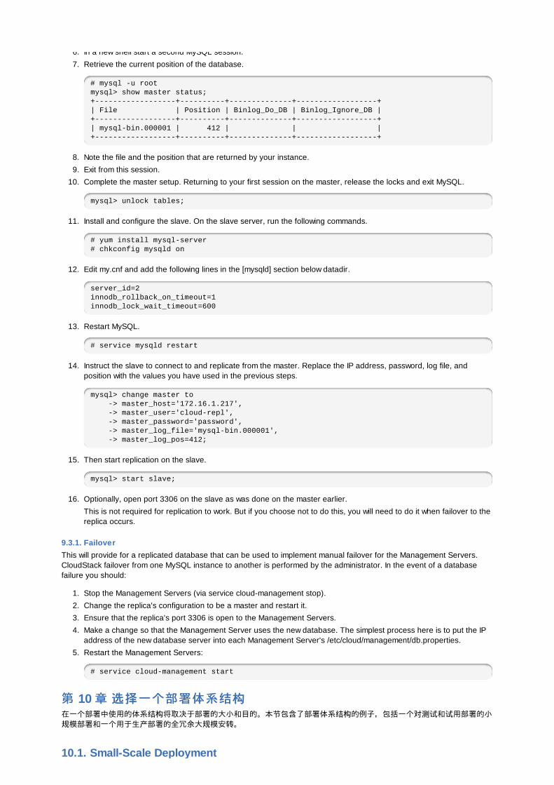
6. In a new shell start a second MySQL session.
7. Retrieve the current position of the database.
# mysql -u rootmysql> show master status;+------------------+----------+--------------+------------------+| File | Position | Binlog_Do_DB | Binlog_Ignore_DB |+------------------+----------+--------------+------------------+| mysql-bin.000001 | 412 | | |+------------------+----------+--------------+------------------+
8. Note the file and the position that are returned by your instance.
9. Exit from this session.
10. Complete the master setup. Returning to your first session on the master, release the locks and exit MySQL.
mysql> unlock tables;
11. Install and configure the slave. On the slave server, run the following commands.
# yum install mysql-server# chkconfig mysqld on
12. Edit my.cnf and add the following lines in the [mysqld] section below datadir.
server_id=2innodb_rollback_on_timeout=1innodb_lock_wait_timeout=600
13. Restart MySQL.
# service mysqld restart
14. Instruct the slave to connect to and replicate from the master. Replace the IP address, password, log file, andposition with the values you have used in the previous steps.
mysql> change master to -> master_host='172.16.1.217', -> master_user='cloud-repl', -> master_password='password', -> master_log_file='mysql-bin.000001', -> master_log_pos=412;
15. Then start replication on the slave.
mysql> start slave;
16. Optionally, open port 3306 on the slave as was done on the master earlier.
This is not required for replication to work. But if you choose not to do this, you will need to do it when failover to thereplica occurs.
9.3.1. FailoverThis will provide for a replicated database that can be used to implement manual failover for the Management Servers.CloudStack failover from one MySQL instance to another is performed by the administrator. In the event of a databasefailure you should:
1. Stop the Management Servers (via service cloud-management stop).
2. Change the replica's configuration to be a master and restart it.
3. Ensure that the replica's port 3306 is open to the Management Servers.
4. Make a change so that the Management Server uses the new database. The simplest process here is to put the IPaddress of the new database server into each Management Server's /etc/cloud/management/db.properties.
5. Restart the Management Servers:
# service cloud-management start
第第 10 章章 选择选择一个部署体系一个部署体系结构结构在一个部署中使用的体系结构将取决于部署的大小和目的。本节包含了部署体系结构的例子,包括一个对测试和试用部署的小规模部署和一个用于生产部署的全冗余大规模安转。
10.1. Small-Scale Deployment

10.1. Small-Scale Deployment
This diagram illustrates the network architecture of a small-scale CloudStack deployment.
A firewall provides a connection to the Internet. The firewall is configured in NAT mode. The firewall forwards HTTPrequests and API calls from the Internet to the Management Server. The Management Server resides on themanagement network.
A layer-2 switch connects all physical servers and storage.
A single NFS server functions as both the primary and secondary storage.
The Management Server is connected to the management network.
10.2. 大大规规模冗余模冗余设设置置
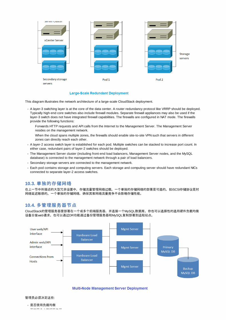
This diagram illustrates the network architecture of a large-scale CloudStack deployment.
A layer-3 switching layer is at the core of the data center. A router redundancy protocol like VRRP should be deployed.Typically high-end core switches also include firewall modules. Separate firewall appliances may also be used if thelayer-3 switch does not have integrated firewall capabilities. The firewalls are configured in NAT mode. The firewallsprovide the following functions:
Forwards HTTP requests and API calls from the Internet to the Management Server. The Management Serverresides on the management network.
When the cloud spans multiple zones, the firewalls should enable site-to-site VPN such that servers in differentzones can directly reach each other.
A layer-2 access switch layer is established for each pod. Multiple switches can be stacked to increase port count. Ineither case, redundant pairs of layer-2 switches should be deployed.
The Management Server cluster (including front-end load balancers, Management Server nodes, and the MySQLdatabase) is connected to the management network through a pair of load balancers.
Secondary storage servers are connected to the management network.
Each pod contains storage and computing servers. Each storage and computing server should have redundant NICsconnected to separate layer-2 access switches.
10.3. 单单独的存独的存储储网网络络在上一节中所描述的大型冗余设置中,存储流量管理网络过载。一个单独的存储网络的部署是可选的。如iSCSI存储协议是对网络延迟敏感的。一个单独的存储网络,确保宾客网络流量竞争不会影响存储性能。
10.4. 多管理服多管理服务务器器节节点点CloudStack的管理服务器要部署在一个或多个前端服务器,并连接一个MySQL数据库。你也可以选择性的选用硬件负载均衡设备分发web请求。也可以通过DR功能通过备份管理服务器和MySQL复制部署到远程站点。
管理员必须决定这些:
是否使用负载均衡要部署多少管理服务器。
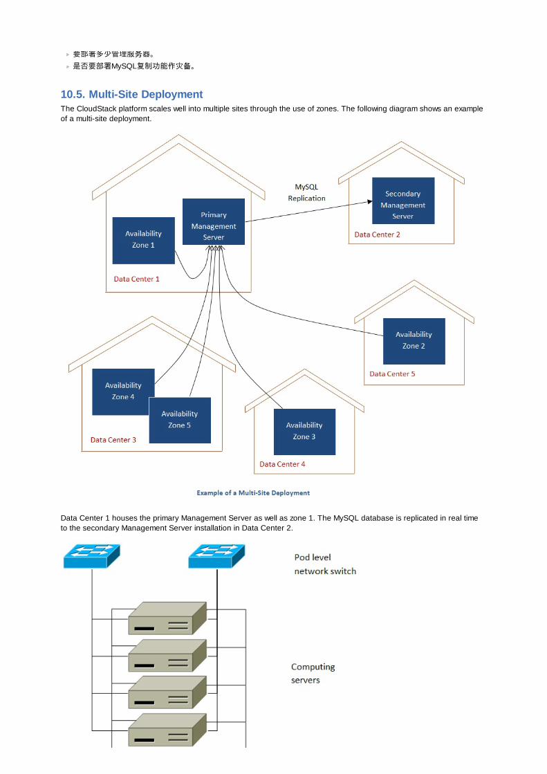
要部署多少管理服务器。是否要部署MySQL复制功能作灾备。
10.5. Multi-Site DeploymentThe CloudStack platform scales well into multiple sites through the use of zones. The following diagram shows an exampleof a multi-site deployment.
Data Center 1 houses the primary Management Server as well as zone 1. The MySQL database is replicated in real timeto the secondary Management Server installation in Data Center 2.
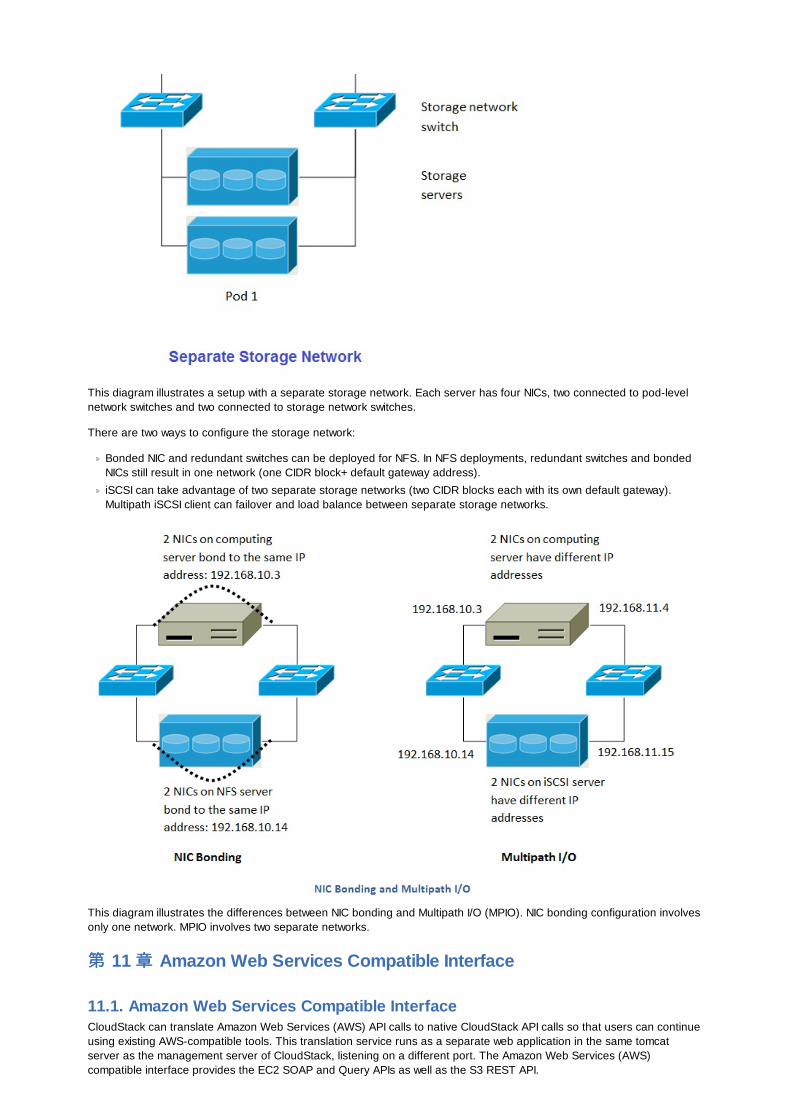
This diagram illustrates a setup with a separate storage network. Each server has four NICs, two connected to pod-levelnetwork switches and two connected to storage network switches.
There are two ways to configure the storage network:
Bonded NIC and redundant switches can be deployed for NFS. In NFS deployments, redundant switches and bondedNICs still result in one network (one CIDR block+ default gateway address).
iSCSI can take advantage of two separate storage networks (two CIDR blocks each with its own default gateway).Multipath iSCSI client can failover and load balance between separate storage networks.
This diagram illustrates the differences between NIC bonding and Multipath I/O (MPIO). NIC bonding configuration involvesonly one network. MPIO involves two separate networks.
第第 11 章章 Amazon Web Services Compatible Interface
11.1. Amazon Web Services Compatible InterfaceCloudStack can translate Amazon Web Services (AWS) API calls to native CloudStack API calls so that users can continueusing existing AWS-compatible tools. This translation service runs as a separate web application in the same tomcatserver as the management server of CloudStack, listening on a different port. The Amazon Web Services (AWS)compatible interface provides the EC2 SOAP and Query APIs as well as the S3 REST API.
注意注意
This service was previously enabled by separate software called CloudBridge. It is now fully integrated with theCloudStack management server.
警告警告
The compatible interface for the EC2 Query API and the S3 API are Work In Progress. The S3 compatible APIoffers a way to store data on the management server file system, it is not an implementation of the S3 backend.
Limitations
Supported only in zones that use basic networking.
Available in fresh installations of CloudStack. Not available through upgrade of previous versions.
Features such as Elastic IP (EIP) and Elastic Load Balacing (ELB) are only available in an infrastructure with a CitrixNetScaler device. Users accessing a Zone with a NetScaler device will need to use a NetScaler-enabled networkoffering (DefaultSharedNetscalerEIP and ELBNetworkOffering).
11.2. Supported API Version
The EC2 interface complies with Amazon's WDSL version dated November 15, 2010, available athttp://ec2.amazonaws.com/doc/2010-11-15/.
The interface is compatible with the EC2 command-line tools EC2 tools v. 1.3.6230, which can be downloaded athttp://s3.amazonaws.com/ec2-downloads/ec2-api-tools-1.3-62308.zip.
注意注意
Work is underway to support a more recent version of the EC2 API
11.3. Enabling the EC2 and S3 Compatible InterfaceThe software that provides AWS API compatibility is installed along with CloudStack. You must enable the services andperform some setup steps prior to using it.
1. Set the global configuration parameters for each service to true. See 第 7 章 设置全局配置参数.
2. Create a set of CloudStack service offerings with names that match the Amazon service offerings. You can do thisthrough the CloudStack UI as described in the Administration Guide.
警告警告
Be sure you have included the Amazon default service offering, m1.small. As well as any EC2 instance typesthat you will use.
3. If you did not already do so when you set the configuration parameter in step 1, restart the Management Server.
# service cloud-management restart
The following sections provides details to perform these steps
11.3.1. Enabling the ServicesTo enable the EC2 and S3 compatible services you need to set the configuration variables enable.ec2.api andenable.s3.api to true. You do not have to enable both at the same time. Enable the ones you need. This can be done viathe CloudStack GUI by going in Global Settings or via the API.
The snapshot below shows you how to use the GUI to enable these services
Using the CloudStack API, the easiest is to use the so-called integration port on which you can make unauthenticatedcalls. In Global Settings set the port to 8096 and subsequently call the updateConfiguration method. The following urlsshows you how:
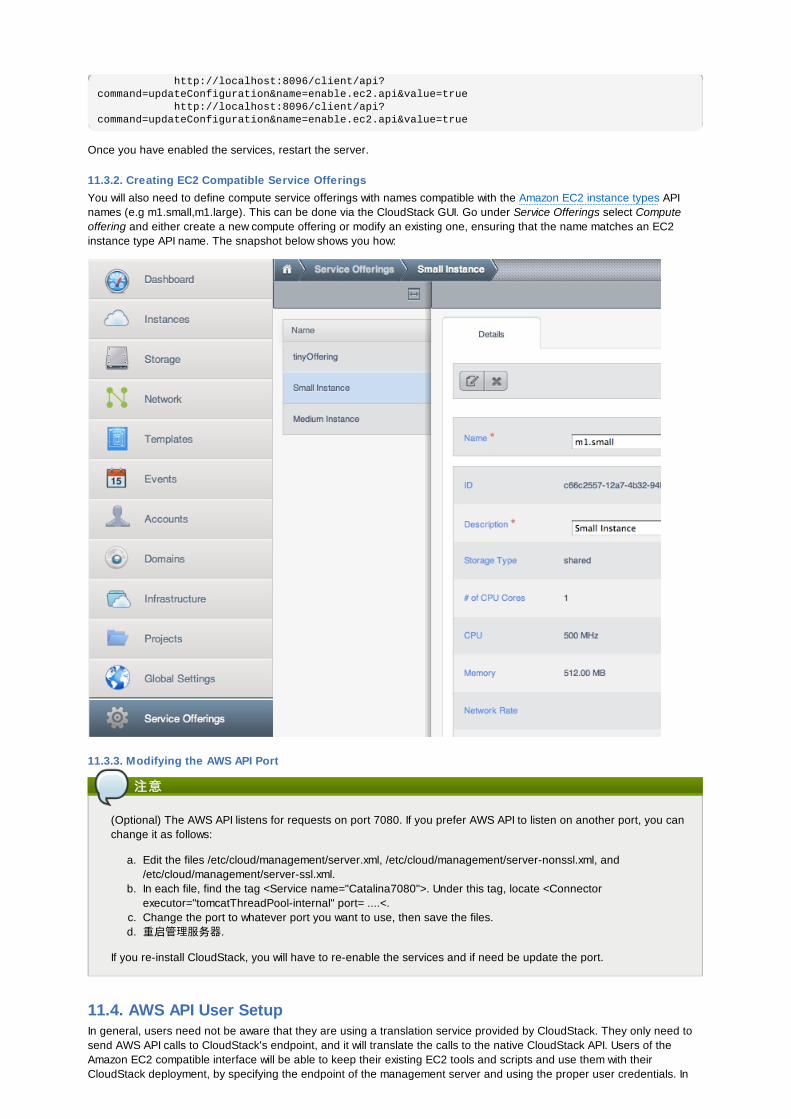
http://localhost:8096/client/api?command=updateConfiguration&name=enable.ec2.api&value=true http://localhost:8096/client/api?command=updateConfiguration&name=enable.ec2.api&value=true
Once you have enabled the services, restart the server.
11.3.2. Creating EC2 Compatible Service OfferingsYou will also need to define compute service offerings with names compatible with the Amazon EC2 instance types APInames (e.g m1.small,m1.large). This can be done via the CloudStack GUI. Go under Service Offerings select Computeoffering and either create a new compute offering or modify an existing one, ensuring that the name matches an EC2instance type API name. The snapshot below shows you how:
11.3.3. Modifying the AWS API Port
注意注意
(Optional) The AWS API listens for requests on port 7080. If you prefer AWS API to listen on another port, you canchange it as follows:
a. Edit the files /etc/cloud/management/server.xml, /etc/cloud/management/server-nonssl.xml, and/etc/cloud/management/server-ssl.xml.
b. In each file, find the tag <Service name="Catalina7080">. Under this tag, locate <Connectorexecutor="tomcatThreadPool-internal" port= ....<.
c. Change the port to whatever port you want to use, then save the files.d. 重启管理服务器.
If you re-install CloudStack, you will have to re-enable the services and if need be update the port.
11.4. AWS API User SetupIn general, users need not be aware that they are using a translation service provided by CloudStack. They only need tosend AWS API calls to CloudStack's endpoint, and it will translate the calls to the native CloudStack API. Users of theAmazon EC2 compatible interface will be able to keep their existing EC2 tools and scripts and use them with theirCloudStack deployment, by specifying the endpoint of the management server and using the proper user credentials. In

order to do this, each user must perform the following configuration steps:
Generate user credentials.
Register with the service.
For convenience, set up environment variables for the EC2 SOAP command-line tools.
11.4.1. AWS API User RegistrationEach user must perform a one-time registration. The user follows these steps:
1. Obtain the following by looking in the CloudStack UI, using the API, or asking the cloud administrator:
The CloudStack server's publicly available DNS name or IP address
The user account's Access key and Secret key
2. Generate a private key and a self-signed X.509 certificate. The user substitutes their own desired storage locationfor /path/to/… below.
$ openssl req -x509 -nodes -days 365 -newkey rsa:2048 -keyout /path/to/private_key.pem -out /path/to/cert.pem
3. Register the user X.509 certificate and Access/Secret keys with the AWS compatible service. If you have the sourcecode of CloudStack go to the awsapi-setup/setup directory and use the Python script cloudstack-aws-api-register. Ifyou do not have the source then download the script using the following command.
wget -O cloudstack-aws-api-register "https://git-wip-us.apache.org/repos/asf?p=incubator-cloudstack.git;a=blob_plain;f=awsapi-setup/setup/cloudstack-aws-api-register;hb=HEAD"
Then execute it, using the access and secret keys that were obtained in step 1. An example is shown below.
$ cloudstack-aws-api-register --apikey=User’s CloudStack API key --secretkey=User’s CloudStack Secret key --cert=/path/to/cert.pem --url=http://CloudStack.server:7080/awsapi
注意注意
A user with an existing AWS certificate could choose to use the same certificate with CloudStack, but note that thecertificate would be uploaded to the CloudStack management server database.
11.4.2. AWS API Command-Line Tools SetupTo use the EC2 command-line tools, the user must perform these steps:
1. Be sure you have the right version of EC2 Tools. The supported version is available athttp://s3.amazonaws.com/ec2-downloads/ec2-api-tools-1.3-62308.zip.
2. Set up the EC2 environment variables. This can be done every time you use the service or you can set them up inthe proper shell profile. Replace the endpoint (i.e EC2_URL) with the proper address of your CloudStackmanagement server and port. In a bash shell do the following.
$ export EC2_CERT=/path/to/cert.pem $ export EC2_PRIVATE_KEY=/path/to/private_key.pem $ export EC2_URL=http://localhost:7080/awsapi $ export EC2_HOME=/path/to/EC2_tools_directory
11.5. Using Timeouts to Ensure AWS API Command CompletionThe Amazon EC2 command-line tools have a default connection timeout. When used with CloudStack, a longer timeoutmight be needed for some commands. If you find that commands are not completing due to timeouts, you can specify acustom timeouts. You can add the following optional command-line parameters to any CloudStack-supported EC2command:
--connection-timeout TIMEOUTSpecifies a connection timeout (in seconds). Example:
--connection-timeout 30
--request-timeout TIMEOUTSpecifies a request timeout (in seconds). Example:
--request-timeout 45
Example:
ec2-run-instances 2 –z us-test1 –n 1-3 --connection-timeout 120 --request-timeout 120
注意注意
The timeouts optional arguments are not specific to CloudStack.
11.6. Supported AWS API CallsThe following Amazon EC2 commands are supported by CloudStack when the AWS API compatible interface is enabled.For a few commands, there are differences between the CloudStack and Amazon EC2 versions, and these differences arenoted. The underlying SOAP call for each command is also given, for those who have built tools using those calls.
表表 11.1. Elastic IP API mapping
EC2 command SOAP call CloudStack API call
ec2-allocate-address AllocateAddress associateIpAddress
ec2-associate-address AssociateAddress enableStaticNat
ec2-describe-addresses DescribeAddresses listPublicIpAddresses
ec2-diassociate-address DisassociateAddress disableStaticNat
ec2-release-address ReleaseAddress disassociateIpAddress
表表 11.2. Availability Zone API mapping
EC2 command SOAP call CloudStack API call
ec2-describe-availability-zones DescribeAvailabilityZones listZones
表表 11.3. Images API mapping
EC2 command SOAP call CloudStack API call
ec2-create-image CreateImage createTemplate
ec2-deregister DeregisterImage DeleteTemplate
ec2-describe-images DescribeImages listTemplates
ec2-register RegisterImage registerTemplate
表表 11.4. Image Attributes API mapping
EC2 command SOAP call CloudStack API call
ec2-describe-image-attribute DescribeImageAttribute listTemplatePermissions
ec2-modify-image-attribute ModifyImageAttribute updateTemplatePermissions
ec2-reset-image-attribute ResetImageAttribute updateTemplatePermissions
表表 11.5. Instances API mapping
EC2 command SOAP call CloudStack API call
ec2-describe-instances DescribeInstances listVirtualMachines
ec2-run-instances RunInstances deployVirtualMachine
ec2-reboot-instances RebootInstances rebootVirtualMachine
ec2-start-instances StartInstances startVirtualMachine
ec2-stop-instances StopInstances stopVirtualMachine
ec2-terminate-instances TerminateInstances destroyVirtualMachine
表表 11.6. Instance Attributes Mapping
EC2 command SOAP call CloudStack API call
ec2-describe-instance-attribute DescribeInstanceAttribute listVirtualMachines
表表 11.7. Keys Pairs Mapping
EC2 command SOAP call CloudStack API call
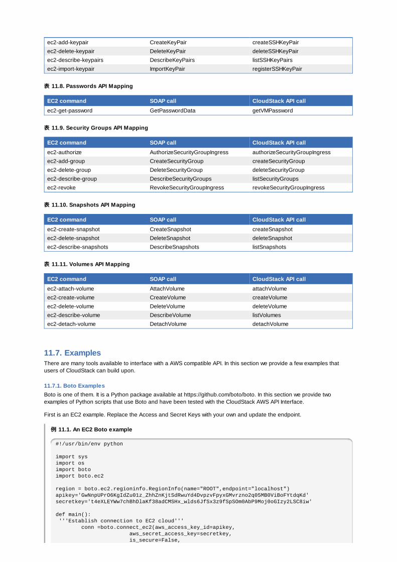
ec2-add-keypair CreateKeyPair createSSHKeyPair
ec2-delete-keypair DeleteKeyPair deleteSSHKeyPair
ec2-describe-keypairs DescribeKeyPairs listSSHKeyPairs
ec2-import-keypair ImportKeyPair registerSSHKeyPair
表表 11.8. Passwords API Mapping
EC2 command SOAP call CloudStack API call
ec2-get-password GetPasswordData getVMPassword
表表 11.9. Security Groups API Mapping
EC2 command SOAP call CloudStack API call
ec2-authorize AuthorizeSecurityGroupIngress authorizeSecurityGroupIngress
ec2-add-group CreateSecurityGroup createSecurityGroup
ec2-delete-group DeleteSecurityGroup deleteSecurityGroup
ec2-describe-group DescribeSecurityGroups listSecurityGroups
ec2-revoke RevokeSecurityGroupIngress revokeSecurityGroupIngress
表表 11.10. Snapshots API Mapping
EC2 command SOAP call CloudStack API call
ec2-create-snapshot CreateSnapshot createSnapshot
ec2-delete-snapshot DeleteSnapshot deleteSnapshot
ec2-describe-snapshots DescribeSnapshots listSnapshots
表表 11.11. Volumes API Mapping
EC2 command SOAP call CloudStack API call
ec2-attach-volume AttachVolume attachVolume
ec2-create-volume CreateVolume createVolume
ec2-delete-volume DeleteVolume deleteVolume
ec2-describe-volume DescribeVolume listVolumes
ec2-detach-volume DetachVolume detachVolume
11.7. ExamplesThere are many tools available to interface with a AWS compatible API. In this section we provide a few examples thatusers of CloudStack can build upon.
11.7.1. Boto ExamplesBoto is one of them. It is a Python package available at https://github.com/boto/boto. In this section we provide twoexamples of Python scripts that use Boto and have been tested with the CloudStack AWS API Interface.
First is an EC2 example. Replace the Access and Secret Keys with your own and update the endpoint.
例例 11.1. An EC2 Boto example
#!/usr/bin/env python
import sysimport osimport botoimport boto.ec2
region = boto.ec2.regioninfo.RegionInfo(name="ROOT",endpoint="localhost")apikey='GwNnpUPrO6KgIdZu01z_ZhhZnKjtSdRwuYd4DvpzvFpyxGMvrzno2q05MB0ViBoFYtdqKd'secretkey='t4eXLEYWw7chBhDlaKf38adCMSHx_wlds6JfSx3z9fSpSOm0AbP9Moj0oGIzy2LSC8iw'
def main(): '''Establish connection to EC2 cloud''' conn =boto.connect_ec2(aws_access_key_id=apikey, aws_secret_access_key=secretkey, is_secure=False,
is_secure=False, region=region, port=7080, path="/awsapi", api_version="2010-11-15")
'''Get list of images that I own''' images = conn.get_all_images() print images myimage = images[0] '''Pick an instance type''' vm_type='m1.small' reservation = myimage.run(instance_type=vm_type,security_groups=['default'])
if __name__ == '__main__': main()
Second is an S3 example. Replace the Access and Secret keys with your own, as well as the endpoint of the service. Besure to also update the file paths to something that exists on your machine.
例例 11.2. An S3 Boto Example
#!/usr/bin/env python
import sysimport osfrom boto.s3.key import Keyfrom boto.s3.connection import S3Connectionfrom boto.s3.connection import OrdinaryCallingFormat
apikey='ChOw-pwdcCFy6fpeyv6kUaR0NnhzmG3tE7HLN2z3OB_s-ogF5HjZtN4rnzKnq2UjtnHeg_yLA5gOw'secretkey='IMY8R7CJQiSGFk4cHwfXXN3DUFXz07cCiU80eM3MCmfLs7kusgyOfm0g9qzXRXhoAPCH-IRxXc3w'
cf=OrdinaryCallingFormat()
def main(): '''Establish connection to S3 service''' conn =S3Connection(aws_access_key_id=apikey,aws_secret_access_key=secretkey, \ is_secure=False, \ host='localhost', \ port=7080, \ calling_format=cf, \ path="/awsapi/rest/AmazonS3")
try: bucket=conn.create_bucket('cloudstack') k = Key(bucket) k.key = 'test' try: k.set_contents_from_filename('/Users/runseb/Desktop/s3cs.py') except: print 'could not write file' pass except: bucket = conn.get_bucket('cloudstack') k = Key(bucket) k.key = 'test' try: k.get_contents_to_filename('/Users/runseb/Desktop/foobar') except: print 'Could not get file' pass
try: bucket1=conn.create_bucket('teststring') k=Key(bucket1) k.key('foobar') k.set_contents_from_string('This is my silly test') except: bucket1=conn.get_bucket('teststring') k = Key(bucket1) k.key='foobar' k.get_contents_as_string() if __name__ == '__main__': main()
11.7.2. JClouds Examples
第第 12 章章 网网络络配置配置对于一个成功的 CloudStack 完成网络配置是至关重要的。这部分包含的信息有助你做出决定和按照正确的流程正确的搭建你的网络。
12.1. Basic and Advanced NetworkingCloudStack provides two styles of networking:.
å ºæ ¬
For AWS-style networking. Provides a single network where guest isolation can be provided through layer-3 means suchas security groups (IP address source filtering).
é« çº§
For more sophisticated network topologies. This network model provides the most flexibility in defining guest networks, butrequires more configuration steps than basic networking.
Each zone has either basic or advanced networking. Once the choice of networking model for a zone has been made andconfigured in CloudStack, it can not be changed. A zone is either basic or advanced for its entire lifetime.
The following table compares the networking features in the two networking models.
Networking Feature Basic Network Advanced Network
Number of networks Single network Multiple networks
Firewall type Physical Physical and Virtual
Load balancer Physical Physical and Virtual
Isolation type Layer 3 Layer 2 and Layer 3
VPN support 否 是
Port forwarding Physical Physical and Virtual
1:1 NAT Physical Physical and Virtual
æº NAT 否 Physical and Virtual
Userdata 是 是
Network usage monitoring sFlow / netFlow at physical router Hypervisor and Virtual Router
DNS和DHCP 是 是
The two types of networking may be in use in the same cloud. However, a given zone must use either Basic Networking orAdvanced Networking.
Different types of network traffic can be segmented on the same physical network. Guest traffic can also be segmented byaccount. To isolate traffic, you can use separate VLANs. If you are using separate VLANs on a single physical network,make sure the VLAN tags are in separate numerical ranges.
12.2. VLAN分配分配实实例例VLAN对于公共流量及来宾流量是必需的. 下面的例子介绍VLAN的分配模型:
VLAN ID 流量流量类类型型 è å ´小于500 管理流量. 为管理保留 CloudStack自身可以访问这些,
Hypervisor, 系统虚拟机等.
500-599 VLAN携带公共流量. CloudStack账号.
600-799 VLAN携带来宾流量 CloudStack账号. 账号指定VLAN从这个VLAN池里选取.
800-899 VLAN携带来宾流量 CloudStack账号. CloudStack选取账号指定的VLAN, 管理员分配到指定的账号.
900-999 VLAN携带来宾流量 CloudStack 账号. 其范围可以是项目,域或所有的账号.
大于1000 保留将来使用
12.3. Example Hardware Configuration

12.3. Example Hardware ConfigurationThis section contains an example configuration of specific switch models for zone-level layer-3 switching. It assumes VLANmanagement protocols, such as VTP or GVRP, have been disabled. The example scripts must be changed appropriately ifyou choose to use VTP or GVRP.
12.3.1. Dell 62xxThe following steps show how a Dell 62xx is configured for zone-level layer-3 switching. These steps assume VLAN 201 isused to route untagged private IPs for pod 1, and pod 1’s layer-2 switch is connected to Ethernet port 1/g1.
The Dell 62xx Series switch supports up to 1024 VLANs.
1. Configure all the VLANs in the database.
vlan databasevlan 200-999exit
2. Configure Ethernet port 1/g1.
interface ethernet 1/g1switchport mode generalswitchport general pvid 201switchport general allowed vlan add 201 untaggedswitchport general allowed vlan add 300-999 taggedexit
The statements configure Ethernet port 1/g1 as follows:
VLAN 201 is the native untagged VLAN for port 1/g1.
All VLANs (300-999) are passed to all the pod-level layer-2 switches.
12.3.2. Cisco 3750以下步骤以Cisco 3750为例来展示如何在资源域级别配置3层交换. 以下步骤假定VLAN 201用做机架1的未标记私有IP的路由,并且机架1的2层交换连至端口GigabitEthernet1/0/1.
1. 设置VTP为透明模式以允许我们使用超过1000的VLAN ID. 因为我们最多用到VLAN 999, VTP透明模式并不是必须的.
vtp mode transparentvlan 200-999exit
2. 配置交换机端口GigabitEthernet1/0/1.
interface GigabitEthernet1/0/1switchport trunk encapsulation dot1qswitchport mode trunkswitchport trunk native vlan 201exit
以下是配置GigabitEthernet1/0/1端口的说明:
VLAN 201是GigabitEthernet1/0/1端口的本地未标记VLAN.
Cisco 默认传递所有的VLAN. 其结果是所有的VLAN (300-999) 都通过了所有的机架一级的2层交换.
12.4. 层层 -2交交换换机(机(2层层交交换换机)机)在pod中层-2交换机提供接入层功能
它通过trunk连接所有vlans中的计算主机它为管理网络提供包含计算和存储主机的流量交换。层-3(三层)交换机将作为这个管理网络的网关。
配置配置实实例例
这部分包含一个指定交换机模式为pod的层-2交换的配置实例。假定vlan管理协议比如vtp或者grvp已经被禁用。如果你使用了vtp或者gvrp下面的脚本必须做相应的修改。
12.4.1. Dell 62xxThe following steps show how a Dell 62xx is configured for pod-level layer-2 switching.
1. Configure all the VLANs in the database.
vlan database
vlan databasevlan 300-999exit
2. VLAN 201 is used to route untagged private IP addresses for pod 1, and pod 1 is connected to this layer-2 switch.
interface range ethernet allswitchport mode generalswitchport general allowed vlan add 300-999 taggedexit
The statements configure all Ethernet ports to function as follows:
All ports are configured the same way.
All VLANs (300-999) are passed through all the ports of the layer-2 switch.
12.4.2. Cisco 3750以下步骤将演示怎么配置cisco 3750 作为pod级别的层-2交换机
1. 设置VTP为透明模式以允许我们使用超过1000的VLAN ID. 因为我们最多用到VLAN 999, VTP透明模式并不是必须的.
vtp mode transparent vlan 300-999 exit
2. 配置所有端口为dot1q,本征vlan为201
interface range GigabitEthernet 1/0/1-24switchport trunk encapsulation dot1q switchport mode trunkswitchport trunk native vlan 201exit
默认情况,cisco允许通过所有vlan。当2个不同端口连接在一起的时cisco交换机控制不同的vlan id。这就是你为什么必须指定vlan 201 为层-2交换机的本征vlan
12.5. Hardware FirewallAll deployments should have a firewall protecting the management server; see Generic Firewall Provisions. Optionally,some deployments may also have a Juniper SRX firewall that will be the default gateway for the guest networks; see第 12.5.2 节 “External Guest Firewall Integration for Juniper SRX (Optional)”.
12.5.1. Generic Firewall ProvisionsThe hardware firewall is required to serve two purposes:
Protect the Management Servers. NAT and port forwarding should be configured to direct traffic from the publicInternet to the Management Servers.
Route management network traffic between multiple zones. Site-to-site VPN should be configured between multiplezones.
To achieve the above purposes you must set up fixed configurations for the firewall. Firewall rules and policies need notchange as users are provisioned into the cloud. Any brand of hardware firewall that supports NAT and site-to-site VPN canbe used.
12.5.2. External Guest Firewall Integration for Juniper SRX (Optional)
注意注意
Available only for guests using advanced networking.
CloudStack provides for direct management of the Juniper SRX series of firewalls. This enables CloudStack to establishstatic NAT mappings from public IPs to guest VMs, and to use the Juniper device in place of the virtual router for firewallservices. You can have one or more Juniper SRX per zone. This feature is optional. If Juniper integration is notprovisioned, CloudStack will use the virtual router for these services.
The Juniper SRX can optionally be used in conjunction with an external load balancer. External Network elements can bedeployed in a side-by-side or inline configuration.
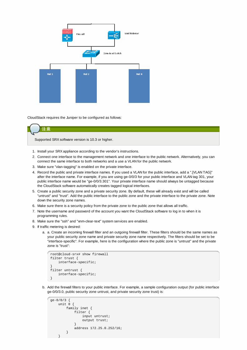
CloudStack requires the Juniper to be configured as follows:
注意注意
Supported SRX software version is 10.3 or higher.
1. Install your SRX appliance according to the vendor's instructions.
2. Connect one interface to the management network and one interface to the public network. Alternatively, you canconnect the same interface to both networks and a use a VLAN for the public network.
3. Make sure "vlan-tagging" is enabled on the private interface.
4. Record the public and private interface names. If you used a VLAN for the public interface, add a ".[VLAN TAG]"after the interface name. For example, if you are using ge-0/0/3 for your public interface and VLAN tag 301, yourpublic interface name would be "ge-0/0/3.301". Your private interface name should always be untagged becausethe CloudStack software automatically creates tagged logical interfaces.
5. Create a public security zone and a private security zone. By default, these will already exist and will be called"untrust" and "trust". Add the public interface to the public zone and the private interface to the private zone. Notedown the security zone names.
6. Make sure there is a security policy from the private zone to the public zone that allows all traffic.
7. Note the username and password of the account you want the CloudStack software to log in to when it isprogramming rules.
8. Make sure the "ssh" and "xnm-clear-text" system services are enabled.
9. If traffic metering is desired:
a. a. Create an incoming firewall filter and an outgoing firewall filter. These filters should be the same names asyour public security zone name and private security zone name respectively. The filters should be set to be"interface-specific". For example, here is the configuration where the public zone is "untrust" and the privatezone is "trust":
root@cloud-srx# show firewallfilter trust { interface-specific;}filter untrust { interface-specific;}
b. Add the firewall filters to your public interface. For example, a sample configuration output (for public interfacege-0/0/3.0, public security zone untrust, and private security zone trust) is:
ge-0/0/3 { unit 0 { family inet { filter { input untrust; output trust; } address 172.25.0.252/16; } }
}
10. Make sure all VLANs are brought to the private interface of the SRX.
11. After the CloudStack Management Server is installed, log in to the CloudStack UI as administrator.
12. In the left navigation bar, click Infrastructure.
13. In Zones, click View More.
14. Choose the zone you want to work with.
15. 点击网络标签。16. In the Network Service Providers node of the diagram, click Configure. (You might have to scroll down to see this.)
17. Click SRX.
18. Click the Add New SRX button (+) and provide the following:
IP Address: The IP address of the SRX.
Username: The user name of the account on the SRX that CloudStack should use.
Password: The password of the account.
Public Interface. The name of the public interface on the SRX. For example, ge-0/0/2. A ".x" at the end of theinterface indicates the VLAN that is in use.
Private Interface: The name of the private interface on the SRX. For example, ge-0/0/1.
Usage Interface: (Optional) Typically, the public interface is used to meter traffic. If you want to use a differentinterface, specify its name here
Number of Retries: The number of times to attempt a command on the SRX before failing. The default value is 2.
Timeout (seconds): The time to wait for a command on the SRX before considering it failed. Default is 300seconds.
Public Network: The name of the public network on the SRX. For example, trust.
Private Network: The name of the private network on the SRX. For example, untrust.
Capacity: The number of networks the device can handle
Dedicated: When marked as dedicated, this device will be dedicated to a single account. When Dedicated ischecked, the value in the Capacity field has no significance implicitly, its value is 1
19. 点击 确定。
20. Click Global Settings. Set the parameter external.network.stats.interval to indicate how often you want CloudStack tofetch network usage statistics from the Juniper SRX. If you are not using the SRX to gather network usage statistics,set to 0.
12.5.3. External Guest Load Balancer Integration (Optional)CloudStack can optionally use a Citrix NetScaler or BigIP F5 load balancer to provide load balancing services to guests. Ifthis is not enabled, CloudStack will use the software load balancer in the virtual router.
To install and enable an external load balancer for CloudStack management:
1. Set up the appliance according to the vendor's directions.
2. Connect it to the networks carrying public traffic and management traffic (these could be the same network).
3. Record the IP address, username, password, public interface name, and private interface name. The interfacenames will be something like "1.1" or "1.2".
4. Make sure that the VLANs are trunked to the management network interface.
5. After the CloudStack Management Server is installed, log in as administrator to the CloudStack UI.
6. In the left navigation bar, click Infrastructure.
7. In Zones, click View More.
8. Choose the zone you want to work with.
9. 点击网络标签。10. In the Network Service Providers node of the diagram, click Configure. (You might have to scroll down to see this.)
11. Click NetScaler or F5.
12. Click the Add button (+) and provide the following:
For NetScaler:
IP Address: The IP address of the SRX.
Username/Password: The authentication credentials to access the device. CloudStack uses these credentials toaccess the device.
Type: The type of device that is being added. It could be F5 Big Ip Load Balancer, NetScaler VPX, NetScalerMPX, or NetScaler SDX. For a comparison of the NetScaler types, see the CloudStack Administration Guide.
Public interface: Interface of device that is configured to be part of the public network.
Private interface: Interface of device that is configured to be part of the private network.
Number of retries. Number of times to attempt a command on the device before considering the operation failed.Default is 2.
Capacity: The number of networks the device can handle.
Dedicated: When marked as dedicated, this device will be dedicated to a single account. When Dedicated ischecked, the value in the Capacity field has no significance implicitly, its value is 1.
13. 点击 确定。
The installation and provisioning of the external load balancer is finished. You can proceed to add VMs and NAT or loadbalancing rules.
12.6. Setting Zone VLAN and Running VM MaximumsCloudStack can use a load balancer to provide a virtual IP for multiple Management Servers. The administrator isresponsible for creating the load balancer rules for the Management Servers. The application requires persistence orstickiness across multiple sessions. The following chart lists the ports that should be load balanced and whether or notpersistence is required.
Even if persistence is not required, enabling it is permitted.
Source Port Destination Port å è®® Persistence Required?
80 or 443 8080 (or 20400 with AJP) HTTP (or AJP) 是
8250 8250 TCP 是
8096 8096 HTTP 否
12.7. 拓扑要求拓扑要求
12.7.1. 安全要求安全要求
不能从公网互联网访问管理服务器8096或者8250端口
12.7.2. Runtime Internal Communications Requirements
The Management Servers communicate with each other to coordinate tasks. This communication uses TCP on ports8250 and 9090.
The console proxy VMs connect to all hosts in the zone over the management traffic network. Therefore themanagement traffic network of any given pod in the zone must have connectivity to the management traffic network ofall other pods in the zone.
The secondary storage VMs and console proxy VMs connect to the Management Server on port 8250. If you are usingmultiple Management Servers, the load balanced IP address of the Management Servers on port 8250 must bereachable.
12.7.3. Storage Network Topology RequirementsThe secondary storage NFS export is mounted by the secondary storage VM. Secondary storage traffic goes over themanagement traffic network, even if there is a separate storage network. Primary storage traffic goes over the storagenetwork, if available. If you choose to place secondary storage NFS servers on the storage network, you must make surethere is a route from the management traffic network to the storage network.
12.7.4. 外部防火外部防火墙墙拓扑要求拓扑要求
当外部防火墙被集成时,公共IP VLAN 必须仍然被直接透传到主机。这被要求用以支持二级存储虚拟机和控制台代理虚拟机。
12.7.5. Advanced Zone Topology RequirementsWith Advanced Networking, separate subnets must be used for private and public networks.
12.7.6. XenServer 拓扑要求拓扑要求
管理服务器通过22(ssh),80(http),443(https)和XenServer主机通信
12.7.7. VMware 拓扑要求拓扑要求
管理服务器和辅助存储vm必须能够访问同一个区域中的vCenter和所有ESXI主机。为了允许必要的访问通过防火墙,保持443端口放行
管理服务器同端口443(https)和VMware vCenter服务器通信在管理流量网络中,管理服务器通过3922端口(3922)和系统vm通信
12.7.8. KVM Topology RequirementsThe Management Servers communicate with KVM hosts on port 22 (ssh).
12.8. Guest Network Usage Integration for Traffic Sentinel

To collect usage data for a guest network, CloudStack needs to pull the data from an external network statistics collectorinstalled on the network. Metering statistics for guest networks are available through CloudStack’s integration with inMonTraffic Sentinel.
Traffic Sentinel is a network traffic usage data collection package. CloudStack can feed statistics from Traffic Sentinel intoits own usage records, providing a basis for billing users of cloud infrastructure. Traffic Sentinel uses the traffic monitoringprotocol sFlow�. Routers and switches generate sFlow records and provide them for collection by Traffic Sentinel, thenCloudStack queries the Traffic Sentinel database to obtain this information
To construct the query, CloudStack determines what guest IPs were in use during the current query interval. This includesboth newly assigned IPs and IPs that were assigned in a previous time period and continued to be in use. CloudStackqueries Traffic Sentinel for network statistics that apply to these IPs during the time period they remained allocated inCloudStack. The returned data is correlated with the customer account that owned each IP and the timestamps when IPswere assigned and released in order to create billable metering records in CloudStack. When the Usage Server runs, itcollects this data.
To set up the integration between CloudStack and Traffic Sentinel:
1. On your network infrastructure, install Traffic Sentinel and configure it to gather traffic data. For installation andconfiguration steps, see inMon documentation at Traffic Sentinel Documentation.
2. In the Traffic Sentinel UI, configure Traffic Sentinel to accept script querying from guest users. CloudStack will bethe guest user performing the remote queries to gather network usage for one or more IP addresses.
Click File > Users > Access Control > Reports Query, then select Guest from the drop-down list.
3. On CloudStack, add the Traffic Sentinel host by calling the CloudStack API command addTrafficMonitor. Pass in theURL of the Traffic Sentinel as protocol + host + port (optional); for example, http://10.147.28.100:8080. For theaddTrafficMonitor command syntax, see the API Reference at API Documentation.
For information about how to call the CloudStack API, see the Developer’s Guide at CloudStack API Developer'sGuide.
4. 以管理员身份登录进入CloudStack 用户界面。5. Select Configuration from the Global Settings page, and set the following:
direct.network.stats.interval: How often you want CloudStack to query Traffic Sentinel.
12.9. Setting Zone VLAN and Running VM MaximumsIn the external networking case, every VM in a zone must have a unique guest IP address. There are two variables thatyou need to consider in determining how to configure CloudStack to support this: how many Zone VLANs do you expect tohave and how many VMs do you expect to have running in the Zone at any one time.
Use the following table to determine how to configure CloudStack for your deployment.
guest.vlan.bits Maximum Running VMs per Zone Maximum Zone VLANs
12 4096 4094
11 8192 2048
10 16384 1024
10 32768 512
Based on your deployment's needs, choose the appropriate value of guest.vlan.bits. Set it as described in Edit the GlobalConfiguration Settings (Optional) section and restart the Management Server.
第第 13 章章 管理网管理网络络和流量和流量在CloudStack ;来宾vms可以通过安全共享架构和其他人通讯,用户感觉像拥有自己的私有网络一样。CloudStack虚拟路由器是为用户提供网络通讯流量的主要组件
13.1. æ ¥å®¾æµ é一个网络只能为在一个zone中的虚拟机之间传输流量。不同zone中的虚拟机不能使用它们自己的ip地址和对方通信;它们必须通过公共ip地址以路由的方式和对方通信。
This figure illustrates a typical guest traffic setup:
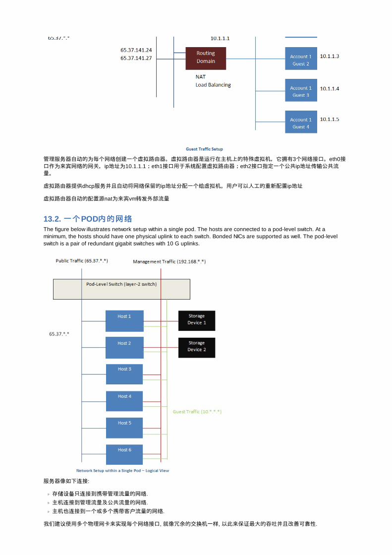
管理服务器自动的为每个网络创建一个虚拟路由器。虚拟路由器是运行在主机上的特殊虚拟机,它拥有3个网络接口。eth0接口作为来宾网络的网关,ip地址为10.1.1.1;eth1接口用于系统配置虚拟路由器;eth2接口指定一个公共ip地址传输公共流量。
虚拟路由器提供dhcp服务并且自动将网络保留的ip地址分配一个给虚拟机。用户可以人工的重新配置ip地址
虚拟路由器自动的配置源nat为来宾vm转发外部流量
13.2. 一个一个POD内的网内的网络络The figure below illustrates network setup within a single pod. The hosts are connected to a pod-level switch. At aminimum, the hosts should have one physical uplink to each switch. Bonded NICs are supported as well. The pod-levelswitch is a pair of redundant gigabit switches with 10 G uplinks.
服务器像如下连接:
存储设备只连接到携带管理流量的网络.
主机连接到管理流量及公共流量的网络.
主机也连接到一个或多个携带客户流量的网络.
我们建议使用多个物理网卡来实现每个网络接口, 就像冗余的交换机一样, 以此来保证最大的吞吐并且改善可靠性.

13.3. 在区域内的在区域内的联联网网The following figure illustrates the network setup within a single zone.
用于管理流量的防火墙工作在NAT模式。通常是分配给网络中的IP地址192.168.0.0/16 B类私有地址空间。每个POD分配的IP地址192.168.*.0/24 C类私有地址空间。
每个区域都有自己的一套公网IP地址。来自不同区域的公网IP地址不重叠。
13.4. 基本区域物理网基本区域物理网络络配置配置在一个基本网络中,配置物理网络相当直接明了。你只需要配置一个宾客网络以承载由宾客虚拟机产生的流量。当你首次增加一个区域到CloudStack中, 你通过Add Zone 屏设置宾客网络。
13.5. 高高级级区物理网区物理网络络配置配置在使用高级联网的区中,你需要告诉管理服务器物理网络是如何安装的以独立地传输不同种类的网络流量。
13.5.1. 在高在高级资级资源域中源域中设设置来置来宾宾流量流量以下步骤假定你已经登录进入 CloudStack 界面。设置基本的来宾网络:
1. 在左边的导航栏,选择基础架构。在区域数量界面点击查看全部,然后点击你要添加网络的区域名。2. 点击网络标签。3. 点击 添加客户网络。添加来宾网络窗口显示:

4. 提供以下信息
名称名称。网络名称。这是对用户可见的。显显示文本示文本 :
区域区域 : 这里的区域是指你要配置来宾网络的区域。网网络络提供方案提供方案 : 如果管理员已经配置了多个网络i共方案,选择你需要的那个。来来宾宾网网络络网关网关 : 来宾网络使用的网关来来宾宾网网络络子网掩子网掩码码 : 来宾网络使用的子网掩码
5. 点击 确定。
13.5.2. 在高在高级级区中配置公用通信区中配置公用通信
在一个使用高级网络配置的区中,你需要配置至少一个用于Internet通信的IP地址范围。
13.6. 使用多个来使用多个来宾宾网网络络在使用高级网络的资源域里, 附加的来宾网络可以在初始安装后任何时间添加. 你还可以通过指定DNS后缀为每个网络自定义关联的域名.
一个虚机的网络在其创建时定义. 当一个虚机创建以后, 就不能对其网络添加删除, 即便用户可以进入客户虚机删除指定网卡的IP地址.
每一个虚机只有一个默认的网络. 在这个默认网络里, 虚拟路由器的DHCP响应将设置客户的默认网关. 除了单一,必须的默认网络, 多个非默认的网络也可以添加到客户虚机里. 管理员可以控制哪个网络作为默认的网络.
附加的网络可以给所有账户使用或者分配给特定的账户. 对所有账户都可用的网络在整个资源域有效. 任何可以访问这个资源域的用户都可以使用这个网络创建虚机. 这些资源域一级的网络基本不提供客户之间的隔离. 分配给特定帐户的网络提供强制隔离的功能.
13.6.1. 添加添加另另一个虚一个虚拟拟机的网机的网络络
1. 作为管理员或最终用户登入到CloudStack UI.
2. 在左边的导航栏里选择网络.
3. 点击添加虚拟机网络。系统给出如下信息:名称名称 : 网络名称。用户可见。显显示文本示文本 : 网络描述。用户可见。区域区域 . 此网络所应用的区域名。每个区域都是一个广播范围,因此对虚拟机网络来说,每个区域都有一个不同的IP范围。管理员必须为每个区域配置IP范围。网网络络提提议议 : 如果管理员已经配置了多个网络提议,为此网络从中选择一个。虚虚拟拟机网关机网关 : 虚拟机应该使用的网关。虚虚拟拟机掩机掩码码 : 虚拟机子网说使用的掩码。
4. 点击创建。
13.6.2. Changing the Network Offering on a Guest NetworkA user or administrator can change the network offering that is associated with an existing guest network.
作为管理员或最终用户登入到CloudStack UI.
If you are changing from a network offering that uses the CloudStack virtual router to one that uses external devices asnetwork service providers, you must first stop all the VMs on the network. See "Stopping and Starting Virtual Machines"in the Administrator's Guide.
在左边的导航栏里选择网络.
Click the name of the network you want to modify.
In the Details tab, click Edit.
In Network Offering, choose the new network offering, then click Apply.

In Network Offering, choose the new network offering, then click Apply.
A prompt is displayed asking whether you want to keep the existing CIDR. This is to let you know that if you change thenetwork offering, the CIDR will be affected. Choose No to proceed with the change.
Wait for the update to complete. Don’t try to restart VMs until the network change is complete.
If you stopped any VMs, restart them.
13.7. 安全分安全分组组
13.7.1. About Security GroupsSecurity groups provide a way to isolate traffic to VMs. A security group is a group of VMs that filter their incoming andoutgoing traffic according to a set of rules, called ingress and egress rules. These rules filter network traffic according tothe IP address that is attempting to communicate with the VM. Security groups are particularly useful in zones that usebasic networking, because there is a single guest network for all guest VMs. In advanced zones, security groups aresupported only on the KVM hypervisor.
注意注意
In a zone that uses advanced networking, you can instead define multiple guest networks to isolate traffic to VMs.
Each CloudStack account comes with a default security group that denies all inbound traffic and allows all outbound traffic.The default security group can be modified so that all new VMs inherit some other desired set of rules.
Any CloudStack user can set up any number of additional security groups. When a new VM is launched, it is assigned tothe default security group unless another user-defined security group is specified. A VM can be a member of any numberof security groups. Once a VM is assigned to a security group, it remains in that group for its entire lifetime; you can notmove a running VM from one security group to another.
You can modify a security group by deleting or adding any number of ingress and egress rules. When you do, the newrules apply to all VMs in the group, whether running or stopped.
If no ingress rules are specified, then no traffic will be allowed in, except for responses to any traffic that has been allowedout through an egress rule.
13.7.2. Adding a Security GroupA user or administrator can define a new security group.
1. 作为管理员或最终用户登入到CloudStack UI.
2. In the left navigation, choose Network
3. In Select view, choose Security Groups.
4. Click Add Security Group.
5. Provide a name and description.
6. 点击 确定。
The new security group appears in the Security Groups Details tab.
7. To make the security group useful, continue to Adding Ingress and Egress Rules to a Security Group.
13.7.3. Security Groups in Advanced Zones (KVM Only)CloudStack provides the ability to use security groups to provide isolation between guests on a single shared, zone-widenetwork in an advanced zone where KVM is the hypervisor. Using security groups in advanced zones rather than multipleVLANs allows a greater range of options for setting up guest isolation in a cloud.
Limitations
The following are not supported for this feature:
Two IP ranges with the same VLAN and different gateway or netmask in security group-enabled shared network.
Two IP ranges with the same VLAN and different gateway or netmask in account-specific shared networks.
Multiple VLAN ranges in security group-enabled shared network.
Multiple VLAN ranges in account-specific shared networks.
Security groups must be enabled in the zone in order for this feature to be used.
13.7.4. 启启用安全用安全组组In order for security groups to function in a zone, the security groups feature must first be enabled for the zone. Theadministrator can do this when creating a new zone, by selecting a network offering that includes security groups. Theprocedure is described in Basic Zone Configuration in the Advanced Installation Guide. The administrator can not enablesecurity groups for an existing zone, only when creating a new zone.
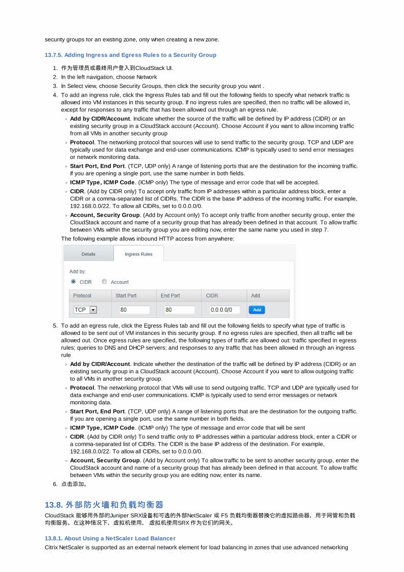
security groups for an existing zone, only when creating a new zone.
13.7.5. Adding Ingress and Egress Rules to a Security Group
1. 作为管理员或最终用户登入到CloudStack UI.
2. In the left navigation, choose Network
3. In Select view, choose Security Groups, then click the security group you want .
4. To add an ingress rule, click the Ingress Rules tab and fill out the following fields to specify what network traffic isallowed into VM instances in this security group. If no ingress rules are specified, then no traffic will be allowed in,except for responses to any traffic that has been allowed out through an egress rule.
Add by CIDR/Account. Indicate whether the source of the traffic will be defined by IP address (CIDR) or anexisting security group in a CloudStack account (Account). Choose Account if you want to allow incoming trafficfrom all VMs in another security group
Protocol. The networking protocol that sources will use to send traffic to the security group. TCP and UDP aretypically used for data exchange and end-user communications. ICMP is typically used to send error messagesor network monitoring data.
Start Port, End Port. (TCP, UDP only) A range of listening ports that are the destination for the incoming traffic.If you are opening a single port, use the same number in both fields.
ICMP Type, ICMP Code . (ICMP only) The type of message and error code that will be accepted.
CIDR. (Add by CIDR only) To accept only traffic from IP addresses within a particular address block, enter aCIDR or a comma-separated list of CIDRs. The CIDR is the base IP address of the incoming traffic. For example,192.168.0.0/22. To allow all CIDRs, set to 0.0.0.0/0.
Account, Security Group. (Add by Account only) To accept only traffic from another security group, enter theCloudStack account and name of a security group that has already been defined in that account. To allow trafficbetween VMs within the security group you are editing now, enter the same name you used in step 7.
The following example allows inbound HTTP access from anywhere:
5. To add an egress rule, click the Egress Rules tab and fill out the following fields to specify what type of traffic isallowed to be sent out of VM instances in this security group. If no egress rules are specified, then all traffic will beallowed out. Once egress rules are specified, the following types of traffic are allowed out: traffic specified in egressrules; queries to DNS and DHCP servers; and responses to any traffic that has been allowed in through an ingressrule
Add by CIDR/Account. Indicate whether the destination of the traffic will be defined by IP address (CIDR) or anexisting security group in a CloudStack account (Account). Choose Account if you want to allow outgoing trafficto all VMs in another security group.
Protocol. The networking protocol that VMs will use to send outgoing traffic. TCP and UDP are typically used fordata exchange and end-user communications. ICMP is typically used to send error messages or networkmonitoring data.
Start Port, End Port. (TCP, UDP only) A range of listening ports that are the destination for the outgoing traffic.If you are opening a single port, use the same number in both fields.
ICMP Type, ICMP Code . (ICMP only) The type of message and error code that will be sent
CIDR. (Add by CIDR only) To send traffic only to IP addresses within a particular address block, enter a CIDR ora comma-separated list of CIDRs. The CIDR is the base IP address of the destination. For example,192.168.0.0/22. To allow all CIDRs, set to 0.0.0.0/0.
Account, Security Group. (Add by Account only) To allow traffic to be sent to another security group, enter theCloudStack account and name of a security group that has already been defined in that account. To allow trafficbetween VMs within the security group you are editing now, enter its name.
6. 点击添加。
13.8. 外部防火外部防火墙墙和和负载负载均衡器均衡器CloudStack 能够用外部的Juniper SRX设备和可选的外部NetScaler 或 F5 负载均衡器替换它的虚拟路由器,用于网管和负载均衡服务。在这种情况下,虚拟机使用, 虚拟机使用SRX 作为它们的网关。
13.8.1. About Using a NetScaler Load BalancerCitrix NetScaler is supported as an external network element for load balancing in zones that use advanced networking(also called advanced zones). Set up an external load balancer when you want to provide load balancing through means
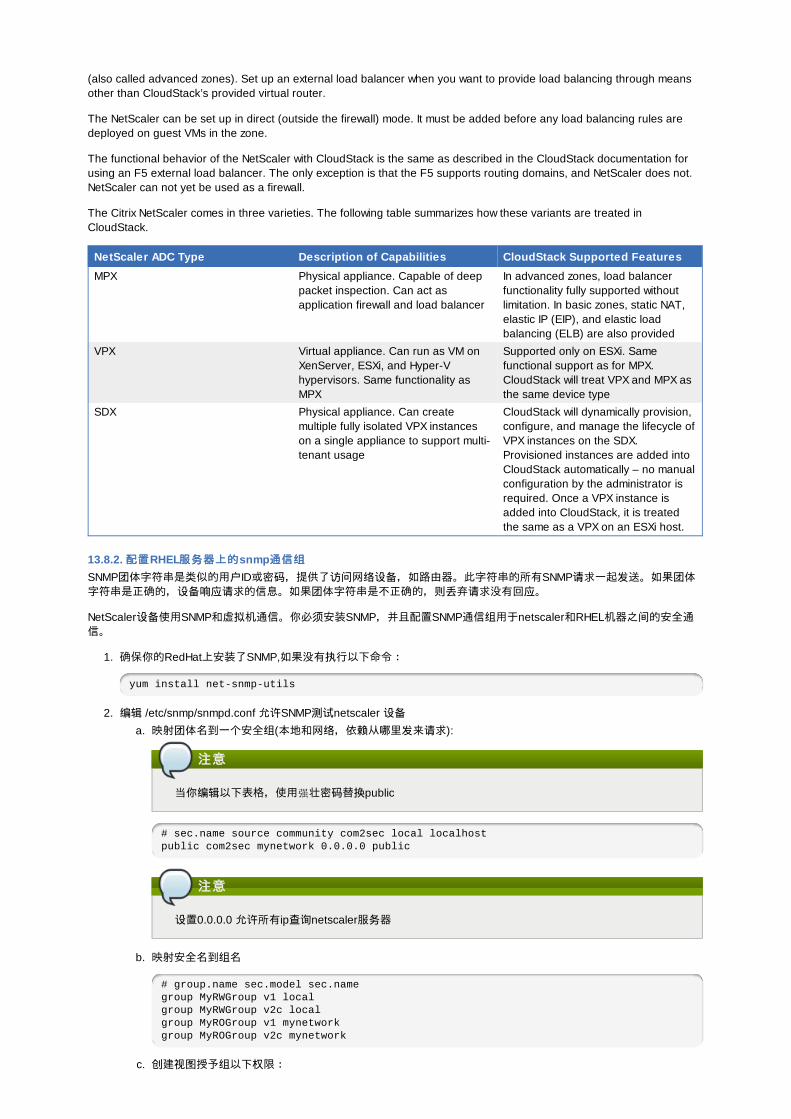
(also called advanced zones). Set up an external load balancer when you want to provide load balancing through meansother than CloudStack’s provided virtual router.
The NetScaler can be set up in direct (outside the firewall) mode. It must be added before any load balancing rules aredeployed on guest VMs in the zone.
The functional behavior of the NetScaler with CloudStack is the same as described in the CloudStack documentation forusing an F5 external load balancer. The only exception is that the F5 supports routing domains, and NetScaler does not.NetScaler can not yet be used as a firewall.
The Citrix NetScaler comes in three varieties. The following table summarizes how these variants are treated inCloudStack.
NetScaler ADC Type Description of Capabilities CloudStack Supported Features
MPX Physical appliance. Capable of deeppacket inspection. Can act asapplication firewall and load balancer
In advanced zones, load balancerfunctionality fully supported withoutlimitation. In basic zones, static NAT,elastic IP (EIP), and elastic loadbalancing (ELB) are also provided
VPX Virtual appliance. Can run as VM onXenServer, ESXi, and Hyper-Vhypervisors. Same functionality asMPX
Supported only on ESXi. Samefunctional support as for MPX.CloudStack will treat VPX and MPX asthe same device type
SDX Physical appliance. Can createmultiple fully isolated VPX instanceson a single appliance to support multi-tenant usage
CloudStack will dynamically provision,configure, and manage the lifecycle ofVPX instances on the SDX.Provisioned instances are added intoCloudStack automatically – no manualconfiguration by the administrator isrequired. Once a VPX instance isadded into CloudStack, it is treatedthe same as a VPX on an ESXi host.
13.8.2. 配置配置RHEL服服务务器上的器上的snmp通信通信组组SNMP团体字符串是类似的用户ID或密码,提供了访问网络设备,如路由器。此字符串的所有SNMP请求一起发送。如果团体字符串是正确的,设备响应请求的信息。如果团体字符串是不正确的,则丢弃请求没有回应。
NetScaler设备使用SNMP和虚拟机通信。你必须安装SNMP,并且配置SNMP通信组用于netscaler和RHEL机器之间的安全通信。
1. 确保你的RedHat上安装了SNMP,如果没有执行以下命令:
yum install net-snmp-utils
2. 编辑 /etc/snmp/snmpd.conf 允许SNMP测试netscaler 设备a. 映射团体名到一个安全组(本地和网络,依赖从哪里发来请求):
注意注意
当你编辑以下表格,使用强壮密码替换public
# sec.name source community com2sec local localhost public com2sec mynetwork 0.0.0.0 public
注意注意
设置0.0.0.0 允许所有ip查询netscaler服务器
b. 映射安全名到组名
# group.name sec.model sec.namegroup MyRWGroup v1 localgroup MyRWGroup v2c localgroup MyROGroup v1 mynetworkgroup MyROGroup v2c mynetwork
c. 创建视图授予组以下权限:
incl/excl subtree mask view all included .1
d. Grant access with different write permissions to the two groups to the view you created.
# context sec.model sec.level prefix read write notifaccess MyROGroup "" any noauth exact all none noneaccess MyRWGroup "" any noauth exact all all all
3. iptalbes 中放行SNMP
iptables -A INPUT -p udp --dport 161 -j ACCEPT
4. 启动SNMP服务
service snmpd start
5. 确保snmp服务随系统自动启动
chkconfig snmpd on
13.8.3. Initial Setup of External Firewalls and Load BalancersWhen the first VM is created for a new account, CloudStack programs the external firewall and load balancer to work withthe VM. The following objects are created on the firewall:
A new logical interface to connect to the account's private VLAN. The interface IP is always the first IP of the account'sprivate subnet (e.g. 10.1.1.1).
A source NAT rule that forwards all outgoing traffic from the account's private VLAN to the public Internet, using theaccount's public IP address as the source address
A firewall filter counter that measures the number of bytes of outgoing traffic for the account
The following objects are created on the load balancer:
A new VLAN that matches the account's provisioned Zone VLAN
A self IP for the VLAN. This is always the second IP of the account's private subnet (e.g. 10.1.1.2).
13.8.4. Ongoing Configuration of External Firewalls and Load BalancersAdditional user actions (e.g. setting a port forward) will cause further programming of the firewall and load balancer. A usermay request additional public IP addresses and forward traffic received at these IPs to specific VMs. This is accomplishedby enabling static NAT for a public IP address, assigning the IP to a VM, and specifying a set of protocols and port rangesto open. When a static NAT rule is created, CloudStack programs the zone's external firewall with the following objects:
A static NAT rule that maps the public IP address to the private IP address of a VM.
A security policy that allows traffic within the set of protocols and port ranges that are specified.
A firewall filter counter that measures the number of bytes of incoming traffic to the public IP.
The number of incoming and outgoing bytes through source NAT, static NAT, and load balancing rules is measured andsaved on each external element. This data is collected on a regular basis and stored in the CloudStack database.
13.8.5. Configuring AutoScaleAutoScaling allows you to scale your back-end services or application VMs up or down seamlessly and automaticallyaccording to the conditions you define. With AutoScaling enabled, you can ensure that the number of VMs you are usingseamlessly scale up when demand increases, and automatically decreases when demand subsides. Thus it helps yousave compute costs by terminating underused VMs automatically and launching new VMs when you need them, withoutthe need for manual intervention.
NetScaler AutoScaling is designed to seamlessly launch or terminate VMs based on user-defined conditions. Conditionsfor triggering a scaleup or scaledown action can vary from a simple use case like monitoring the CPU usage of a server toa complex use case of monitoring a combination of server's responsiveness and its CPU usage. For example, you canconfigure AutoScaling to launch an additional VM whenever CPU usage exceeds 80 percent for 15 minutes, or to removea VM whenever CPU usage is less than 20 percent for 30 minutes.
CloudStack uses the NetScaler load balancer to monitor all aspects of a system's health and work in unison withCloudStack to initiate scale-up or scale-down actions.
注意注意
AutoScale is supported on NetScaler Release 10 Build 73.e and beyond.
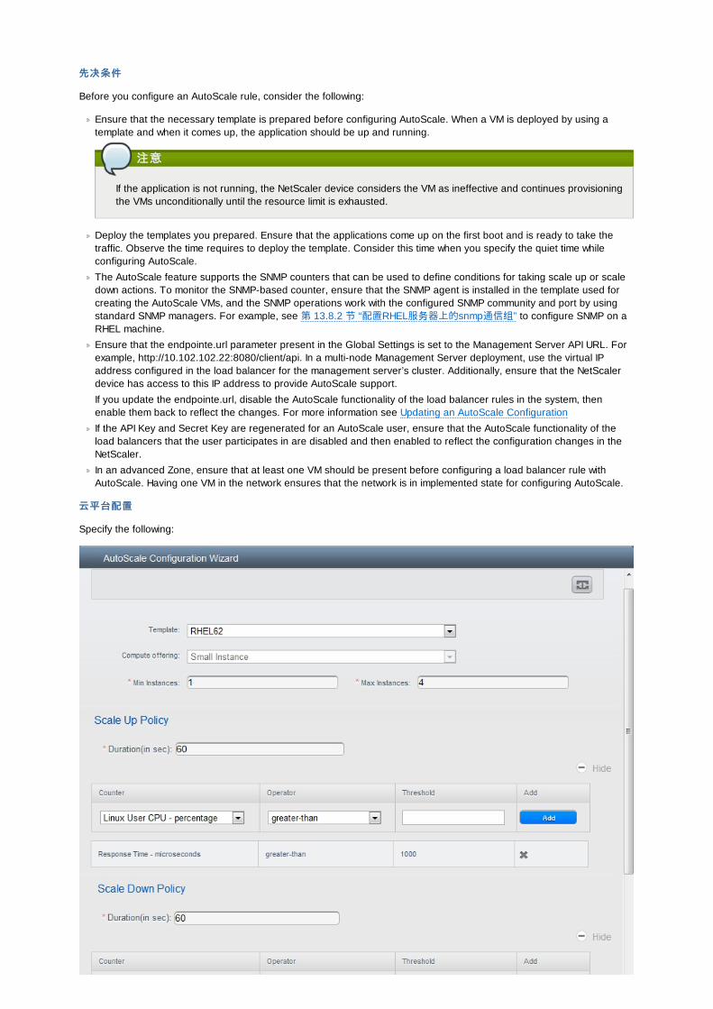
先决条件先决条件
Before you configure an AutoScale rule, consider the following:
Ensure that the necessary template is prepared before configuring AutoScale. When a VM is deployed by using atemplate and when it comes up, the application should be up and running.
注意注意
If the application is not running, the NetScaler device considers the VM as ineffective and continues provisioningthe VMs unconditionally until the resource limit is exhausted.
Deploy the templates you prepared. Ensure that the applications come up on the first boot and is ready to take thetraffic. Observe the time requires to deploy the template. Consider this time when you specify the quiet time whileconfiguring AutoScale.
The AutoScale feature supports the SNMP counters that can be used to define conditions for taking scale up or scaledown actions. To monitor the SNMP-based counter, ensure that the SNMP agent is installed in the template used forcreating the AutoScale VMs, and the SNMP operations work with the configured SNMP community and port by usingstandard SNMP managers. For example, see 第 13.8.2 节 “配置RHEL服务器上的snmp通信组” to configure SNMP on aRHEL machine.
Ensure that the endpointe.url parameter present in the Global Settings is set to the Management Server API URL. Forexample, http://10.102.102.22:8080/client/api. In a multi-node Management Server deployment, use the virtual IPaddress configured in the load balancer for the management server’s cluster. Additionally, ensure that the NetScalerdevice has access to this IP address to provide AutoScale support.
If you update the endpointe.url, disable the AutoScale functionality of the load balancer rules in the system, thenenable them back to reflect the changes. For more information see Updating an AutoScale Configuration
If the API Key and Secret Key are regenerated for an AutoScale user, ensure that the AutoScale functionality of theload balancers that the user participates in are disabled and then enabled to reflect the configuration changes in theNetScaler.
In an advanced Zone, ensure that at least one VM should be present before configuring a load balancer rule withAutoScale. Having one VM in the network ensures that the network is in implemented state for configuring AutoScale.
云平台配置云平台配置
Specify the following:
Template : A template consists of a base OS image and application. A template is used to provision the new instanceof an application on a scaleup action. When a VM is deployed from a template, the VM can start taking the traffic fromthe load balancer without any admin intervention. For example, if the VM is deployed for a Web service, it should havethe Web server running, the database connected, and so on.
Compute offering: A predefined set of virtual hardware attributes, including CPU speed, number of CPUs, and RAMsize, that the user can select when creating a new virtual machine instance. Choose one of the compute offerings to beused while provisioning a VM instance as part of scaleup action.
Min Instance : The minimum number of active VM instances that is assigned to a load balancing rule. The active VMinstances are the application instances that are up and serving the traffic, and are being load balanced. Thisparameter ensures that a load balancing rule has at least the configured number of active VM instances are availableto serve the traffic.
注意注意
If an application, such as SAP, running on a VM instance is down for some reason, the VM is then not countedas part of Min Instance parameter, and the AutoScale feature initiates a scaleup action if the number of activeVM instances is below the configured value. Similarly, when an application instance comes up from its earlierdown state, this application instance is counted as part of the active instance count and the AutoScale processinitiates a scaledown action when the active instance count breaches the Max instance value.
Max Instance : Maximum number of active VM instances that should be assigned to a load balancing rule. Thisparameter defines the upper limit of active VM instances that can be assigned to a load balancing rule.
Specifying a large value for the maximum instance parameter might result in provisioning large number of VMinstances, which in turn leads to a single load balancing rule exhausting the VM instances limit specified at the accountor domain level.
注意注意
If an application, such as SAP, running on a VM instance is down for some reason, the VM is not counted aspart of Max Instance parameter. So there may be scenarios where the number of VMs provisioned for a scaleupaction might be more than the configured Max Instance value. Once the application instances in the VMs are upfrom an earlier down state, the AutoScale feature starts aligning to the configured Max Instance value.
Specify the following scale-up and scale-down policies:
Duration: The duration, in seconds, for which the conditions you specify must be true to trigger a scaleup action. Theconditions defined should hold true for the entire duration you specify for an AutoScale action to be invoked.
Counter: The performance counters expose the state of the monitored instances. By default, CloudStack offers fourperformance counters: Three SNMP counters and one NetScaler counter. The SNMP counters are Linux User CPU,Linux System CPU, and Linux CPU Idle. The NetScaler counter is ResponseTime. The root administrator can addadditional counters into CloudStack by using the CloudStack API.
Operator: The following five relational operators are supported in AutoScale feature: Greater than, Less than, Lessthan or equal to, Greater than or equal to, and Equal to.
Threshold: Threshold value to be used for the counter. Once the counter defined above breaches the thresholdvalue, the AutoScale feature initiates a scaleup or scaledown action.
Add: Click Add to add the condition.
Additionally, if you want to configure the advanced settings, click Show advanced settings, and specify the following:
Polling interval: Frequency in which the conditions, combination of counter, operator and threshold, are to beevaluated before taking a scale up or down action. The default polling interval is 30 seconds.
Quiet Time : This is the cool down period after an AutoScale action is initiated. The time includes the time taken tocomplete provisioning a VM instance from its template and the time taken by an application to be ready to serve traffic.This quiet time allows the fleet to come up to a stable state before any action can take place. The default is 300seconds.
Destroy VM Grace Period: The duration in seconds, after a scaledown action is initiated, to wait before the VM isdestroyed as part of scaledown action. This is to ensure graceful close of any pending sessions or transactions beingserved by the VM marked for destroy. The default is 120 seconds.
Security Groups: Security groups provide a way to isolate traffic to the VM instances. A security group is a group ofVMs that filter their incoming and outgoing traffic according to a set of rules, called ingress and egress rules. Theserules filter network traffic according to the IP address that is attempting to communicate with the VM.
Disk Offerings: A predefined set of disk size for primary data storage.
SNMP Community: The SNMP community string to be used by the NetScaler device to query the configured counter
SNMP Community: The SNMP community string to be used by the NetScaler device to query the configured countervalue from the provisioned VM instances. Default is public.
SNMP Port: The port number on which the SNMP agent that run on the provisioned VMs is listening. Default port is161.
User: This is the user that the NetScaler device use to invoke scaleup and scaledown API calls to the cloud. If nooption is specified, the user who configures AutoScaling is applied. Specify another user name to override.
Apply: Click Apply to create the AutoScale configuration.
Disabling and Enabling an AutoScale Configuration
If you want to perform any maintenance operation on the AutoScale VM instances, disable the AutoScale configuration.When the AutoScale configuration is disabled, no scaleup or scaledown action is performed. You can use this downtime
for the maintenance activities. To disable the AutoScale configuration, click the Disable AutoScale button.
The button toggles between enable and disable, depending on whether AutoScale is currently enabled or not. After themaintenance operations are done, you can enable the AutoScale configuration back. To enable, open the AutoScale
configuration page again, then click the Enable AutoScale button.
Updating an AutoScale Configuration
You can update the various parameters and add or delete the conditions in a scaleup or scaledown rule. Before youupdate an AutoScale configuration, ensure that you disable the AutoScale load balancer rule by clicking the DisableAutoScale button.
After you modify the required AutoScale parameters, click Apply. To apply the new AutoScale policies, open the AutoScaleconfiguration page again, then click the Enable AutoScale button.
Runtime Considerations
An administrator should not assign a VM to a load balancing rule which is configured for AutoScale.
Before a VM provisioning is completed if NetScaler is shutdown or restarted, the provisioned VM cannot be a part ofthe load balancing rule though the intent was to assign it to a load balancing rule. To workaround, rename theAutoScale provisioned VMs based on the rule name or ID so at any point of time the VMs can be reconciled to its loadbalancing rule.
Making API calls outside the context of AutoScale, such as destroyVM, on an autoscaled VM leaves the load balancingconfiguration in an inconsistent state. Though VM is destroyed from the load balancer rule, NetScaler continues toshow the VM as a service assigned to a rule.
13.9. 负载负载均衡均衡规则规则本产品用户或管理员能创建来自于公共IP到一个或多个虚拟机之间流量的负载均衡规则。用户创建规则指定算法,然后将规则分配给一个虚拟机集合。
注意注意
如果你创建的负载均衡规则同时使用的网络提供方案使用到了外部的负载均衡器设备(比如NetScaler),随后又改变为使用虚拟路由器的网络提供方案,你必须在虚拟路由器上为每个已存在的负载聚恒规则创建一个防火墙规则以使它们继续生效。
13.9.1. Adding a Load Balancer Rule
1. 作为管理员或最终用户登入到CloudStack UI.
2. 在左边的导航栏里选择网络.
3. Click the name of the network where you want to load balance the traffic.
4. 点击查看IP地址.
5. Click the IP address for which you want to create the rule, then click the Configuration tab.
6. In the Load Balancing node of the diagram, click View All.
In a Basic zone, you can also create a load balancing rule without acquiring or selecting an IP address. CloudStackinternally assign an IP when you create the load balancing rule, which is listed in the IP Addresses page when therule is created.
To do that, select the name of the network, then click Add Load Balancer tab. Continue with 7.
7. Fill in the following:
Name : A name for the load balancer rule.
Public Port: The port receiving incoming traffic to be balanced.
Private Port: The port that the VMs will use to receive the traffic.
Algorithm: Choose the load balancing algorithm you want CloudStack to use. CloudStack supports a variety ofwell-known algorithms. If you are not familiar with these choices, you will find plenty of information about them onthe Internet.
Stickiness: (Optional) Click Configure and choose the algorithm for the stickiness policy. See Sticky SessionPolicies for Load Balancer Rules.
AutoScale : Click Configure and complete the AutoScale configuration as explained in 第 13.8.5 节 “ConfiguringAutoScale”.
8. Click Add VMs, then select two or more VMs that will divide the load of incoming traffic, and click Apply.
The new load balancer rule appears in the list. You can repeat these steps to add more load balancer rules for thisIP address.
13.9.2. Sticky Session Policies for Load Balancer RulesSticky sessions are used in Web-based applications to ensure continued availability of information across the multiplerequests in a user's session. For example, if a shopper is filling a cart, you need to remember what has been purchasedso far. The concept of "stickiness" is also referred to as persistence or maintaining state.
Any load balancer rule defined in CloudStack can have a stickiness policy. The policy consists of a name, stickinessmethod, and parameters. The parameters are name-value pairs or flags, which are defined by the load balancer vendor.The stickiness method could be load balancer-generated cookie, application-generated cookie, or source-based. In thesource-based method, the source IP address is used to identify the user and locate the user’s stored data. In the othermethods, cookies are used. The cookie generated by the load balancer or application is included in request and responseURLs to create persistence. The cookie name can be specified by the administrator or automatically generated. A varietyof options are provided to control the exact behavior of cookies, such as how they are generated and whether they arecached.
For the most up to date list of available stickiness methods, see the CloudStack UI or call listNetworks and check theSupportedStickinessMethods capability.
13.10. 宾宾客客 IP范范围围宾客网络流量的IP是由用户以帐号为基础设置的。这允许用户以在他们的宾客网络和他们的客户端之间开通VPN连接的方式配置他们的网络。
13.11. 获获得一个新的得一个新的 IP地址地址
1. 作为管理员或最终用户登入到CloudStack UI.
2. 在左边的导航栏里选择网络.
3. 点击你想要与之工作的网络名称.
4. 点击查看IP地址.
5. 点击获得一个新IP, 并且在确认的对话框中点击确定.
你被要求点击确认是因为, 通常IP地址是有限的资源. 在稍等片刻之后, 新的IP地址将会出现并且状态是已分配. 你现在可以使用这个IP地址进行端口转发或静态NAT规则.
13.12. Releasing an IP AddressWhen the last rule for an IP address is removed, you can release that IP address. The IP address still belongs to the VPC;however, it can be picked up for any guest network again.
1. 作为管理员或最终用户登入到CloudStack UI.
2. 在左边的导航栏里选择网络.
3. 点击你想要与之工作的网络名称.
4. 点击查看IP地址.
5. Click the IP address you want to release.
6. Click the Release IP button.
13.13. 静静态态 NATA static NAT rule maps a public IP address to the private IP address of a VM in order to allow Internet traffic into the VM.The public IP address always remains the same, which is why it is called “static” NAT. This section tells how to enable ordisable static NAT for a particular IP address.
13.13.1. Enabling or Disabling Static NATIf port forwarding rules are already in effect for an IP address, you cannot enable static NAT to that IP.
If a guest VM is part of more than one network, static NAT rules will function only if they are defined on the default network.
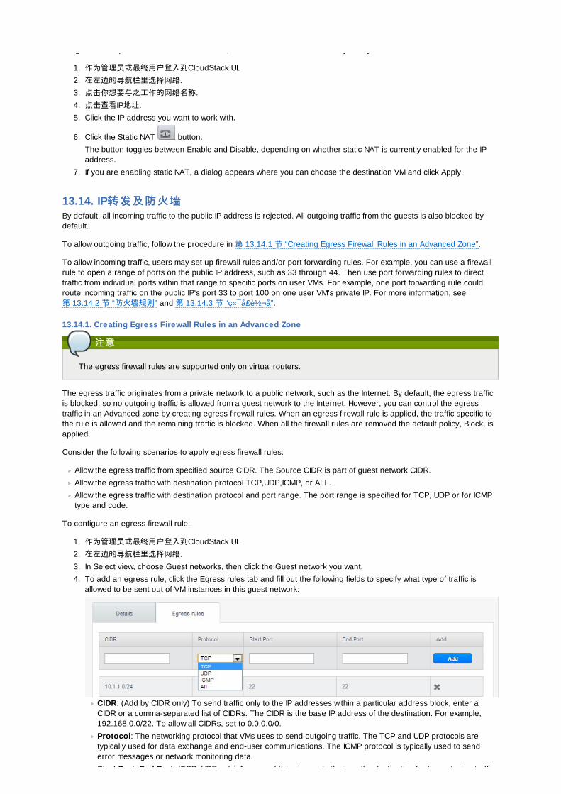
If a guest VM is part of more than one network, static NAT rules will function only if they are defined on the default network.
1. 作为管理员或最终用户登入到CloudStack UI.
2. 在左边的导航栏里选择网络.
3. 点击你想要与之工作的网络名称.
4. 点击查看IP地址.
5. Click the IP address you want to work with.
6. Click the Static NAT button.
The button toggles between Enable and Disable, depending on whether static NAT is currently enabled for the IPaddress.
7. If you are enabling static NAT, a dialog appears where you can choose the destination VM and click Apply.
13.14. IP转发转发及防火及防火墙墙By default, all incoming traffic to the public IP address is rejected. All outgoing traffic from the guests is also blocked bydefault.
To allow outgoing traffic, follow the procedure in 第 13.14.1 节 “Creating Egress Firewall Rules in an Advanced Zone”.
To allow incoming traffic, users may set up firewall rules and/or port forwarding rules. For example, you can use a firewallrule to open a range of ports on the public IP address, such as 33 through 44. Then use port forwarding rules to directtraffic from individual ports within that range to specific ports on user VMs. For example, one port forwarding rule couldroute incoming traffic on the public IP's port 33 to port 100 on one user VM's private IP. For more information, see第 13.14.2 节 “防火墙规则” and 第 13.14.3 节 “ç«¯å £è½¬å ”.
13.14.1. Creating Egress Firewall Rules in an Advanced Zone
注意注意
The egress firewall rules are supported only on virtual routers.
The egress traffic originates from a private network to a public network, such as the Internet. By default, the egress trafficis blocked, so no outgoing traffic is allowed from a guest network to the Internet. However, you can control the egresstraffic in an Advanced zone by creating egress firewall rules. When an egress firewall rule is applied, the traffic specific tothe rule is allowed and the remaining traffic is blocked. When all the firewall rules are removed the default policy, Block, isapplied.
Consider the following scenarios to apply egress firewall rules:
Allow the egress traffic from specified source CIDR. The Source CIDR is part of guest network CIDR.
Allow the egress traffic with destination protocol TCP,UDP,ICMP, or ALL.
Allow the egress traffic with destination protocol and port range. The port range is specified for TCP, UDP or for ICMPtype and code.
To configure an egress firewall rule:
1. 作为管理员或最终用户登入到CloudStack UI.
2. 在左边的导航栏里选择网络.
3. In Select view, choose Guest networks, then click the Guest network you want.
4. To add an egress rule, click the Egress rules tab and fill out the following fields to specify what type of traffic isallowed to be sent out of VM instances in this guest network:
CIDR: (Add by CIDR only) To send traffic only to the IP addresses within a particular address block, enter aCIDR or a comma-separated list of CIDRs. The CIDR is the base IP address of the destination. For example,192.168.0.0/22. To allow all CIDRs, set to 0.0.0.0/0.
Protocol: The networking protocol that VMs uses to send outgoing traffic. The TCP and UDP protocols aretypically used for data exchange and end-user communications. The ICMP protocol is typically used to senderror messages or network monitoring data.
Start Port, End Port: (TCP, UDP only) A range of listening ports that are the destination for the outgoing traffic.

Start Port, End Port: (TCP, UDP only) A range of listening ports that are the destination for the outgoing traffic.If you are opening a single port, use the same number in both fields.
ICMP Type, ICMP Code : (ICMP only) The type of message and error code that are sent.
5. 点击添加.
13.14.2. 防火防火墙规则墙规则默认情况下,防火墙拒绝所有流入公共IP的流量。要是需要允许外部流量,你需要通过制定防火墙规则打开防火墙端口。你可以选择性的制定一个或多个CIDR(无类别域际路由选择,这个说法太晦涩,你可以理解为一个IP网络)来过滤来源IP。这在当你只需要允许特定IP请求时会很有用。
你不能使用防火墙规则打开弹性IP端口。当弹性IP处在使用状态时,外部的通过请求将被安全组管理。详情查看第 13.7.2 节“Adding a Security Group”。
In an advanced zone, you can also create egress firewall rules by using the virtual router. For more information, see第 13.14.1 节 “Creating Egress Firewall Rules in an Advanced Zone”.
防火墙规则能在管理服务器的web UI的防火墙表里创建,这个规则表默认不显示,你需要以管理员身份修改全局变量firewall.rule.ui.enabled为 "true"才能显示。
如果你想创建防火墙规则:
1. 以用户或管理员身份登录进入WebUI。
2. 在左边的导航,选择网络3. 选择你要修改的网络名称4. 点击 查看IP地址
5. 点击你要修改的IP地址
6. 点击设置标签 填入以下值来源来源CIDR。(可选)只允许在某个特定地址块的IP流量的话,输入一个CIDR或者一个逗号隔开的CIDR列表。例如:192.168.0.0/22或者192.168.0.0/24,192.168.1.0/24,192.168.2.0/24。留空则为允许所有的CIDR。
协议协议 . 你所要开反复端口所使用的网络协议。起始端口和起始端口和结结束端口束端口 . 你想要在防火墙开放的端口。如果你只打开单个端口,在两个空格中填入相同的端口号。ICMP 类类型和型和编编号号 .。只有在设置ICMP协议时才会用到。提供需要填写的ICMP协议,ICMP头的类型和代码。如果你不知道天什么请参看ICMP文档。(这里推荐一个http://wenku.baidu.com/view/e235e8ecaeaad1f346933fed.html)
7. 点击添加.
13.14.3. ç«¯å £è½¬å A port forward service is a set of port forwarding rules that define a policy. A port forward service is then applied to one ormore guest VMs. The guest VM then has its inbound network access managed according to the policy defined by the portforwarding service. You can optionally specify one or more CIDRs to filter the source IPs. This is useful when you want toallow only incoming requests from certain IP addresses to be forwarded.
A guest VM can be in any number of port forward services. Port forward services can be defined but have no members. Ifa guest VM is part of more than one network, port forwarding rules will function only if they are defined on the defaultnetwork
You cannot use port forwarding to open ports for an elastic IP address. When elastic IP is used, outside access is insteadcontrolled through the use of security groups. See Security Groups.
To set up port forwarding:
1. 登陆到CloudStack界面以管理员或者终端用户。2. If you have not already done so, add a public IP address range to a zone in CloudStack. See Adding a Zone and
Pod in the Installation Guide.
3. Add one or more VM instances to CloudStack.
4. In the left navigation bar, click Network.
5. Click the name of the guest network where the VMs are running.
6. Choose an existing IP address or acquire a new IP address. See 第 13.11 节 “获得一个新的IP地址”. Click the nameof the IP address in the list.
7. Click the Configuration tab.
8. In the Port Forwarding node of the diagram, click View All.
9. Fill in the following:
Public Port. The port to which public traffic will be addressed on the IP address you acquired in the previousstep.
Private Port. The port on which the instance is listening for forwarded public traffic.
Protocol. The communication protocol in use between the two ports
10. 点击添加。
10. 点击添加。
13.15. IP负载负载均衡均衡用户可以选择关联到同一个公网IP的多个宾客虚拟机。CloudStack实现了TCP级别的负载平衡器,有一下策略。
轮询最少连接源IP
这类似于端口转发,但目标可能会有多个IP地址。
13.16. DNS和和DHCP虚拟路由器为客户机提供DNS和DHCP服服务。它将DNS请求代理到在可用性区中配置的DNS服务器。
13.17. VPN 虚虚拟专拟专用网用网CloudStack account拥有者可以建立 VPN 以便访问他们的虚拟机。如果来宾网络 从一个提供 远程VPN访问服务的网络实例化,虚拟路由(在 System VM上的)将被用于提供服务。\nCloudStack 提供了一个 基于 L2TP-over-IPsec-based 协议的远程VPN访问服务 给 guest虚拟网络。 因为每个网络有它自己的 虚拟路由, VPNs 没有在这些网络中被共享。Windows, Mac OSX和iOS的原生(自带) VPN客户端 可以用于访问 来宾网络。account拥有者可以建立并管理他们的VPN用户。CloudStack 不使用自己账户数据库,而是用了另外一个独立的表。VPN用户数据库在同一个account拥有者建立的VPN网络中被共享。 也就是说,同一个account拥有者建立里的全部VPN可以被它的全部VPN用户访问。
注意注意
确保不是所有的网络流量走VPN。也就是说,用于配置VPN的route不是唯一用于该guest network,也不承担全部的网络流量。
Road Warrior / Remote Access 公路勇士公路勇士 /远远程程访问访问 .用户希望可以安全地从家里或者办公室连接到云上的一个 私有网络。特别是连接的客户端的IP地址是动态决定的,不能预先配置到VPN 服务器上。Site to Site . In this scenario, two private subnets are connected over the public Internet with a secure VPN tunnel. Thecloud user’s subnet (for example, an office network) is connected through a gateway to the network in the cloud. Theaddress of the user’s gateway must be preconfigured on the VPN server in the cloud. Note that although L2TP-over-IPsec can be used to set up Site-to-Site VPNs, this is not the primary intent of this feature. For more information, see第 13.17.4 节 “配置站点到站点的VPN连接”
13.17.1. Configuring VPNTo set up VPN for the cloud:
1. 作为管理员或最终用户登入到CloudStack UI.
2. In the left navigation, click Global Settings.
3. Set the following global configuration parameters.
remote.access.vpn.client.ip.range – The range of IP addressess to be allocated to remote access VPN clients.The first IP in the range is used by the VPN server.
remote.access.vpn.psk.length – Length of the IPSec key.
remote.access.vpn.user.limit – Maximum number of VPN users per account.
To enable VPN for a particular network:
1. Log in as a user or administrator to the CloudStack UI.
2. In the left navigation, click Network.
3. Click the name of the network you want to work with.
4. 点击查看IP地址.
5. Click one of the displayed IP address names.
6. Click the Enable VPN button.
The IPsec key is displayed in a popup window.
13.17.2. Using VPN with WindowsThe procedure to use VPN varies by Windows version. Generally, the user must edit the VPN properties and make surethat the default route is not the VPN. The following steps are for Windows L2TP clients on Windows Vista. The commandsshould be similar for other Windows versions.
1. Log in to the CloudStack UI and click on the source NAT IP for the account. The VPN tab should display the IPsec
1. Log in to the CloudStack UI and click on the source NAT IP for the account. The VPN tab should display the IPsecpreshared key. Make a note of this and the source NAT IP. The UI also lists one or more users and their passwords.Choose one of these users, or, if none exists, add a user and password.
2. On the Windows box, go to Control Panel, then select Network and Sharing center. Click Setup a connection ornetwork.
3. In the next dialog, select No, create a new connection.
4. In the next dialog, select Use my Internet Connection (VPN).
5. In the next dialog, enter the source NAT IP from step 1 and give the connection a name. Check Don't connect now.
6. In the next dialog, enter the user name and password selected in step 1.
7. Click Create.
8. Go back to the Control Panel and click Network Connections to see the new connection. The connection is notactive yet.
9. Right-click the new connection and select Properties. In the Properties dialog, select the Networking tab.
10. In Type of VPN, choose L2TP IPsec VPN, then click IPsec settings. Select Use preshared key. Enter the presharedkey from Step 1.
11. The connection is ready for activation. Go back to Control Panel -> Network Connections and double-click thecreated connection.
12. Enter the user name and password from Step 1.
13.17.3. 在在Mac OS X上使用上使用VPNFirst, be sure you've configured the VPN settings in your CloudStack install. This section is only concerned withconnecting via Mac OS X to your VPN.
Note, these instructions were written on Mac OS X 10.7.5. They may differ slightly in older or newer releases of Mac OS X.
1. On your Mac, open System Preferences and click Network.
2. Make sure Send all traffic over VPN connection is not checked.
3. If your preferences are locked, you'll need to click the lock in the bottom left-hand corner to make any changes andprovide your administrator credentials.
4. You will need to create a new network entry. Click the plus icon on the bottom left-hand side and you'll see a dialogthat says "Select the interface and enter a name for the new service." Select VPN from the Interface drop-downmenu, and "L2TP over IPSec" for the VPN Type. Enter whatever you like within the "Service Name" field.
5. You'll now have a new network interface with the name of whatever you put in the "Service Name" field. For thepurposes of this example, we'll assume you've named it "CloudStack." Click on that interface and provide the IPaddress of the interface for your VPN under the Server Address field, and the user name for your VPN underAccount Name.
6. Click Authentication Settings, and add the user's password under User Authentication and enter the pre-sharedIPSec key in the Shared Secret field under Machine Authentication. Click OK.
7. You may also want to click the "Show VPN status in menu bar" but that's entirely optional.
8. Now click "Connect" and you will be connected to the CloudStack VPN.
13.17.4. 配置站点到站点的配置站点到站点的VPN连连接接一个站点到站点的VPN连接可以帮助你建立从云基础架构到企业内部数据中心的安全连接.这就允许一个账户从企业内部数据中心的设备连接到此账户启用VPN连接的虚拟路由器上, 从而通过VPN连接到该账户的虚拟机.
目前支持的数据中心的终端设备是:
Cisco ISR IOS 12.4或更新
Juniper J-系统 路由器 JunOS 9.5 或更新版本
注意注意
除了上述指定的Cisco和Juniper设备, 所期望的是任何Cisco或Juniper的设备在支持的操作系统上都可以建立VPN连接.
为了建立站点到站点的VPN连接, 需要执行以下步骤:
1. 创建一个虚拟私有云(VPC).
参见第 13.19 节 “Configuring a Virtual Private Cloud”.
2. 创建一个VPN客户网关.
3. 为你创建的VPC设定一个VPN网关.
4. 从VPC的VPN网关到客户的VPN网关建立VPN连接.
注意注意
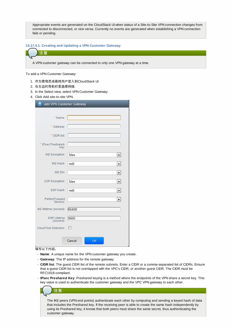
Appropriate events are generated on the CloudStack UI when status of a Site-to-Site VPN connection changes fromconnected to disconnected, or vice versa. Currently no events are generated when establishing a VPN connectionfails or pending.
13.17.4.1. Creating and Updating a VPN Customer Gateway
注意注意
A VPN customer gateway can be connected to only one VPN gateway at a time.
To add a VPN Customer Gateway:
1. 作为管理员或最终用户登入到CloudStack UI.
2. 在左边的导航栏里选择网络.
3. In the Select view, select VPN Customer Gateway.
4. Click Add site-to-site VPN.
填写以下内容。
Name : A unique name for the VPN customer gateway you create.
Gateway: The IP address for the remote gateway.
CIDR list: The guest CIDR list of the remote subnets. Enter a CIDR or a comma-separated list of CIDRs. Ensurethat a guest CIDR list is not overlapped with the VPC’s CIDR, or another guest CIDR. The CIDR must beRFC1918-compliant.
IPsec Preshared Key: Preshared keying is a method where the endpoints of the VPN share a secret key. Thiskey value is used to authenticate the customer gateway and the VPC VPN gateway to each other.
注意注意
The IKE peers (VPN end points) authenticate each other by computing and sending a keyed hash of datathat includes the Preshared key. If the receiving peer is able to create the same hash independently byusing its Preshared key, it knows that both peers must share the same secret, thus authenticating thecustomer gateway.
IKE Encryption: The Internet Key Exchange (IKE) policy for phase-1. The supported encryption algorithms areAES128, AES192, AES256, and 3DES. Authentication is accomplished through the Preshared Keys.
注意注意
The phase-1 is the first phase in the IKE process. In this initial negotiation phase, the two VPN endpointsagree on the methods to be used to provide security for the underlying IP traffic. The phase-1authenticates the two VPN gateways to each other, by confirming that the remote gateway has a matchingPreshared Key.
IKE Hash: The IKE hash for phase-1. The supported hash algorithms are SHA1 and MD5.
IKE DH: A public-key cryptography protocol which allows two parties to establish a shared secret over aninsecure communications channel. The 1536-bit Diffie-Hellman group is used within IKE to establish sessionkeys. The supported options are None, Group-5 (1536-bit) and Group-2 (1024-bit).
ESP Encryption: Encapsulating Security Payload (ESP) algorithm within phase-2. The supported encryptionalgorithms are AES128, AES192, AES256, and 3DES.
注意注意
The phase-2 is the second phase in the IKE process. The purpose of IKE phase-2 is to negotiate IPSecsecurity associations (SA) to set up the IPSec tunnel. In phase-2, new keying material is extracted fromthe Diffie-Hellman key exchange in phase-1, to provide session keys to use in protecting the VPN dataflow.
ESP Hash: Encapsulating Security Payload (ESP) hash for phase-2. Supported hash algorithms are SHA1 andMD5.
Perfect Forward Secrecy: Perfect Forward Secrecy (or PFS) is the property that ensures that a session keyderived from a set of long-term public and private keys will not be compromised. This property enforces a newDiffie-Hellman key exchange. It provides the keying material that has greater key material life and therebygreater resistance to cryptographic attacks. The available options are None, Group-5 (1536-bit) and Group-2(1024-bit). The security of the key exchanges increase as the DH groups grow larger, as does the time of theexchanges.
注意注意
When PFS is turned on, for every negotiation of a new phase-2 SA the two gateways must generate anew set of phase-1 keys. This adds an extra layer of protection that PFS adds, which ensures if thephase-2 SA’s have expired, the keys used for new phase-2 SA’s have not been generated from thecurrent phase-1 keying material.
IKE Lifetime (seconds): The phase-1 lifetime of the security association in seconds. Default is 86400 seconds(1 day). Whenever the time expires, a new phase-1 exchange is performed.
ESP Lifetime (seconds): The phase-2 lifetime of the security association in seconds. Default is 3600 seconds(1 hour). Whenever the value is exceeded, a re-key is initiated to provide a new IPsec encryption andauthentication session keys.
Dead Peer Detection: A method to detect an unavailable Internet Key Exchange (IKE) peer. Select this optionif you want the virtual router to query the liveliness of its IKE peer at regular intervals. It’s recommended to havethe same configuration of DPD on both side of VPN connection.
5. 点击 确定。
Updating and Removing a VPN Customer Gateway
You can update a customer gateway either with no VPN connection, or related VPN connection is in error state.
1. 作为管理员或最终用户登入到CloudStack UI.
2. 在左边的导航栏里选择网络.
3. In the Select view, select VPN Customer Gateway.
4. Select the VPN customer gateway you want to work with.
5. To modify the required parameters, click the Edit VPN Customer Gateway button
6. To remove the VPN customer gateway, click the Delete VPN Customer Gateway button
7. 点击 确定。
13.17.4.2. Creating a VPN gateway for the VPC
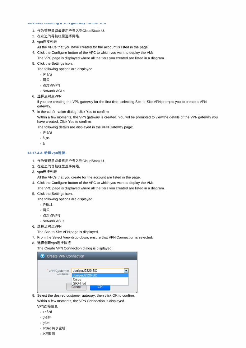
13.17.4.2. Creating a VPN gateway for the VPC
1. 作为管理员或最终用户登入到CloudStack UI.
2. 在左边的导航栏里选择网络.
3. vpn连接列表All the VPCs that you have created for the account is listed in the page.
4. Click the Configure button of the VPC to which you want to deploy the VMs.
The VPC page is displayed where all the tiers you created are listed in a diagram.
5. Click the Settings icon.
The following options are displayed.
IP å °å 网关
点对点VPN
Network ACLs
6. 选择点对点VPN
If you are creating the VPN gateway for the first time, selecting Site-to-Site VPN prompts you to create a VPNgateway.
7. In the confirmation dialog, click Yes to confirm.
Within a few moments, the VPN gateway is created. You will be prompted to view the details of the VPN gateway youhave created. Click Yes to confirm.
The following details are displayed in the VPN Gateway page:
IP å °å å¸ æ·å
13.17.4.3. 新建新建vpn连连接接
1. 作为管理员或最终用户登入到CloudStack UI.
2. 在左边的导航栏里选择网络.
3. vpn连接列表All the VPCs that you create for the account are listed in the page.
4. Click the Configure button of the VPC to which you want to deploy the VMs.
The VPC page is displayed where all the tiers you created are listed in a diagram.
5. Click the Settings icon.
The following options are displayed.
IP地址
网关
点对点VPN
Network ASLs
6. 选择点对点VPN
The Site-to-Site VPN page is displayed.
7. From the Select View drop-down, ensure that VPN Connection is selected.
8. 选择创建vpn连接按钮The Create VPN Connection dialog is displayed:
9. Select the desired customer gateway, then click OK to confirm.
Within a few moments, the VPN Connection is displayed.
VPN连接信息IP å °å ç½ å ³ç ¶æIPSec共享密钥IKE密钥
ESP密钥
13.17.4.4. Restarting and Removing a VPN Connection
1. 登陆到CloudStack界面以管理员或者终端用户。2. 在左边的导航,选择网络3. vpn连接列表
All the VPCs that you have created for the account is listed in the page.
4. Click the Configure button of the VPC to which you want to deploy the VMs.
The VPC page is displayed where all the tiers you created are listed in a diagram.
5. Click the Settings icon.
The following options are displayed.
IP å °å 网关
点对点VPN
Network ASLs
6. Select Site-to-Site VPN.
The Site-to-Site VPN page is displayed.
7. From the Select View drop-down, ensure that VPN Connection is selected.
All the VPN connections you created are displayed.
8. Select the VPN connection you want to work with.
The Details tab is displayed.
9. To remove a VPN connection, click the Delete VPN connection button
To restart a VPN connection, click the Reset VPN connection button present in the Details tab.
13.18. About Inter-VLAN RoutingInter-VLAN Routing is the capability to route network traffic between VLANs. This feature enables you to build VirtualPrivate Clouds (VPC), an isolated segment of your cloud, that can hold multi-tier applications. These tiers are deployed ondifferent VLANs that can communicate with each other. You provision VLANs to the tiers your create, and VMs can bedeployed on different tiers. The VLANs are connected to a virtual router, which facilitates communication between theVMs. In effect, you can segment VMs by means of VLANs into different networks that can host multi-tier applications, suchas Web, Application, or Database. Such segmentation by means of VLANs logically separate application VMs for highersecurity and lower broadcasts, while remaining physically connected to the same device.
This feature is supported on XenServer and VMware hypervisors.
The major advantages are:
The administrator can deploy a set of VLANs and allow users to deploy VMs on these VLANs. A guest VLAN israndomly alloted to an account from a pre-specified set of guest VLANs. All the VMs of a certain tier of an accountreside on the guest VLAN allotted to that account.
注意注意
A VLAN allocated for an account cannot be shared between multiple accounts.
The administrator can allow users create their own VPC and deploy the application. In this scenario, the VMs thatbelong to the account are deployed on the VLANs allotted to that account.
Both administrators and users can create multiple VPCs. The guest network NIC is plugged to the VPC virtual routerwhen the first VM is deployed in a tier.
The administrator can create the following gateways to send to or receive traffic from the VMs:
VPN Gateway: For more information, see 第 13.17.4.2 节 “Creating a VPN gateway for the VPC”.
Public Gateway: The public gateway for a VPC is added to the virtual router when the virtual router is created forVPC. The public gateway is not exposed to the end users. You are not allowed to list it, nor allowed to create anystatic routes.
Private Gateway: For more information, see 第 13.19.5 节 “Adding a Private Gateway to a VPC”.
Both administrators and users can create various possible destinations-gateway combinations. However, only onegateway of each type can be used in a deployment.
For example:
VLANs and Public Gateway: For example, an application is deployed in the cloud, and the Web application VMscommunicate with the Internet.

VLANs, VPN Gateway, and Public Gateway: For example, an application is deployed in the cloud; the Webapplication VMs communicate with the Internet; and the database VMs communicate with the on-premise devices.
The administrator can define Access Control List (ACL) on the virtual router to filter the traffic among the VLANs orbetween the Internet and a VLAN. You can define ACL based on CIDR, port range, protocol, type code (if ICMPprotocol is selected) and Ingress/Egress type.
The following figure shows the possible deployment scenarios of a Inter-VLAN setup:
To set up a multi-tier Inter-VLAN deployment, see 第 13.19 节 “Configuring a Virtual Private Cloud”.
13.19. Configuring a Virtual Private Cloud
13.19.1. About Virtual Private CloudsCloudStack Virtual Private Cloud is a private, isolated part of CloudStack. A VPC can have its own virtual network topologythat resembles a traditional physical network. You can launch VMs in the virtual network that can have private addressesin the range of your choice, for example: 10.0.0.0/16. You can define network tiers within your VPC network range, whichin turn enables you to group similar kinds of instances based on IP address range.
For example, if a VPC has the private range 10.0.0.0/16, its guest networks can have the network ranges 10.0.1.0/24,10.0.2.0/24, 10.0.3.0/24, and so on.
Major Components of a VPC:
A VPC is comprised of the following network components:
VPC: A VPC acts as a container for multiple isolated networks that can communicate with each other via its virtualrouter.
Network Tiers: Each tier acts as an isolated network with its own VLANs and CIDR list, where you can place groups ofresources, such as VMs. The tiers are segmented by means of VLANs. The NIC of each tier acts as its gateway.
Virtual Router: A virtual router is automatically created and started when you create a VPC. The virtual routerconnect the tiers and direct traffic among the public gateway, the VPN gateways, and the NAT instances. For each tier,a corresponding NIC and IP exist in the virtual router. The virtual router provides DNS and DHCP services through itsIP.
Public Gateway: The traffic to and from the Internet routed to the VPC through the public gateway. In a VPC, thepublic gateway is not exposed to the end user; therefore, static routes are not support for the public gateway.
Private Gateway: All the traffic to and from a private network routed to the VPC through the private gateway. Formore information, see 第 13.19.5 节 “Adding a Private Gateway to a VPC”.
VPN Gateway: The VPC side of a VPN connection.
Site-to-Site VPN Connection: A hardware-based VPN connection between your VPC and your datacenter, homenetwork, or co-location facility. For more information, see 第 13.17.4 节 “配置站点到站点的VPN连接”.
Customer Gateway: The customer side of a VPN Connection. For more information, see 第 13.17.4.1 节 “Creatingand Updating a VPN Customer Gateway”.
NAT Instance : An instance that provides Port Address Translation for instances to access the Internet via the public
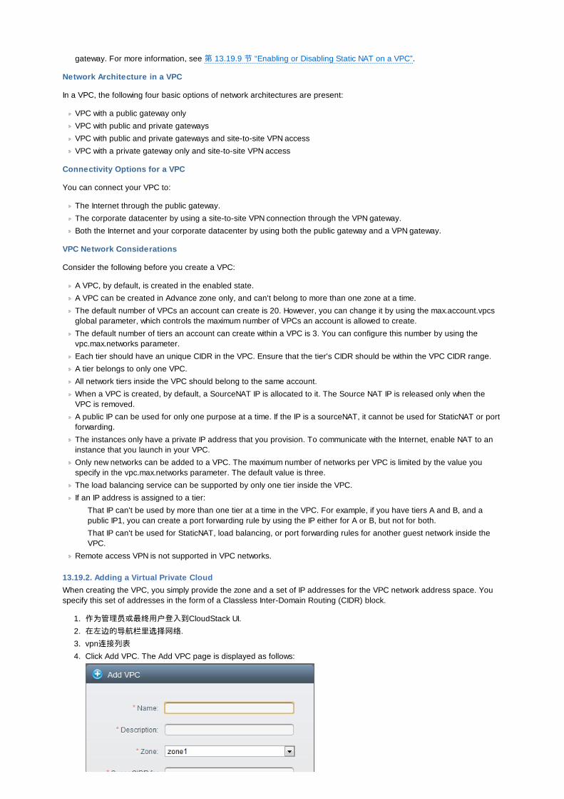
gateway. For more information, see 第 13.19.9 节 “Enabling or Disabling Static NAT on a VPC”.
Network Architecture in a VPC
In a VPC, the following four basic options of network architectures are present:
VPC with a public gateway only
VPC with public and private gateways
VPC with public and private gateways and site-to-site VPN access
VPC with a private gateway only and site-to-site VPN access
Connectivity Options for a VPC
You can connect your VPC to:
The Internet through the public gateway.
The corporate datacenter by using a site-to-site VPN connection through the VPN gateway.
Both the Internet and your corporate datacenter by using both the public gateway and a VPN gateway.
VPC Network Considerations
Consider the following before you create a VPC:
A VPC, by default, is created in the enabled state.
A VPC can be created in Advance zone only, and can't belong to more than one zone at a time.
The default number of VPCs an account can create is 20. However, you can change it by using the max.account.vpcsglobal parameter, which controls the maximum number of VPCs an account is allowed to create.
The default number of tiers an account can create within a VPC is 3. You can configure this number by using thevpc.max.networks parameter.
Each tier should have an unique CIDR in the VPC. Ensure that the tier's CIDR should be within the VPC CIDR range.
A tier belongs to only one VPC.
All network tiers inside the VPC should belong to the same account.
When a VPC is created, by default, a SourceNAT IP is allocated to it. The Source NAT IP is released only when theVPC is removed.
A public IP can be used for only one purpose at a time. If the IP is a sourceNAT, it cannot be used for StaticNAT or portforwarding.
The instances only have a private IP address that you provision. To communicate with the Internet, enable NAT to aninstance that you launch in your VPC.
Only new networks can be added to a VPC. The maximum number of networks per VPC is limited by the value youspecify in the vpc.max.networks parameter. The default value is three.
The load balancing service can be supported by only one tier inside the VPC.
If an IP address is assigned to a tier:
That IP can't be used by more than one tier at a time in the VPC. For example, if you have tiers A and B, and apublic IP1, you can create a port forwarding rule by using the IP either for A or B, but not for both.
That IP can't be used for StaticNAT, load balancing, or port forwarding rules for another guest network inside theVPC.
Remote access VPN is not supported in VPC networks.
13.19.2. Adding a Virtual Private CloudWhen creating the VPC, you simply provide the zone and a set of IP addresses for the VPC network address space. Youspecify this set of addresses in the form of a Classless Inter-Domain Routing (CIDR) block.
1. 作为管理员或最终用户登入到CloudStack UI.
2. 在左边的导航栏里选择网络.
3. vpn连接列表4. Click Add VPC. The Add VPC page is displayed as follows:
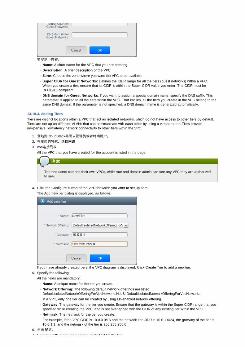
填写以下内容。
Name : A short name for the VPC that you are creating.
Description: A brief description of the VPC.
Zone : Choose the zone where you want the VPC to be available.
Super CIDR for Guest Networks: Defines the CIDR range for all the tiers (guest networks) within a VPC.When you create a tier, ensure that its CIDR is within the Super CIDR value you enter. The CIDR must beRFC1918 compliant.
DNS domain for Guest Networks: If you want to assign a special domain name, specify the DNS suffix. Thisparameter is applied to all the tiers within the VPC. That implies, all the tiers you create in the VPC belong to thesame DNS domain. If the parameter is not specified, a DNS domain name is generated automatically.
13.19.3. Adding TiersTiers are distinct locations within a VPC that act as isolated networks, which do not have access to other tiers by default.Tiers are set up on different VLANs that can communicate with each other by using a virtual router. Tiers provideinexpensive, low latency network connectivity to other tiers within the VPC.
1. 登陆到CloudStack界面以管理员或者终端用户。2. 在左边的导航,选择网络3. vpn连接列表
All the VPC that you have created for the account is listed in the page.
注意注意
The end users can see their own VPCs, while root and domain admin can see any VPC they are authorizedto see.
4. Click the Configure button of the VPC for which you want to set up tiers.
The Add new tier dialog is displayed, as follows:
If you have already created tiers, the VPC diagram is displayed. Click Create Tier to add a new tier.
5. Specify the following:
All the fields are mandatory.
Name : A unique name for the tier you create.
Network Offering: The following default network offerings are listed:DefaultIsolatedNetworkOfferingForVpcNetworksNoLB, DefaultIsolatedNetworkOfferingForVpcNetworks
In a VPC, only one tier can be created by using LB-enabled network offering.
Gateway: The gateway for the tier you create. Ensure that the gateway is within the Super CIDR range that youspecified while creating the VPC, and is not overlapped with the CIDR of any existing tier within the VPC.
Netmask: The netmask for the tier you create.
For example, if the VPC CIDR is 10.0.0.0/16 and the network tier CIDR is 10.0.1.0/24, the gateway of the tier is10.0.1.1, and the netmask of the tier is 255.255.255.0.
6. 点击 确定。
7. Continue with configuring access control list for the tier.

7. Continue with configuring access control list for the tier.
13.19.4. Configuring Access Control ListDefine Network Access Control List (ACL) on the VPC virtual router to control incoming (ingress) and outgoing (egress)traffic between the VPC tiers, and the tiers and Internet. By default, all incoming and outgoing traffic to the guest networksis blocked. To open the ports, you must create a new network ACL. The network ACLs can be created for the tiers only ifthe NetworkACL service is supported.
1. 作为管理员或最终用户登入到CloudStack UI.
2. 在左边的导航栏里选择网络.
3. vpn连接列表All the VPCs that you have created for the account is listed in the page.
4. Click the Settings icon.
The following options are displayed.
IP地址
网关
点对点VPN
Network ACLs
5. Select Network ACLs.
The Network ACLs page is displayed.
6. Click Add Network ACLs.
To add an ACL rule, fill in the following fields to specify what kind of network traffic is allowed in this tier.
CIDR: The CIDR acts as the Source CIDR for the Ingress rules, and Destination CIDR for the Egress rules. Toaccept traffic only from or to the IP addresses within a particular address block, enter a CIDR or a comma-separated list of CIDRs. The CIDR is the base IP address of the incoming traffic. For example, 192.168.0.0/22.To allow all CIDRs, set to 0.0.0.0/0.
Protocol: The networking protocol that sources use to send traffic to the tier. The TCP and UDP protocols aretypically used for data exchange and end-user communications. The ICMP protocol is typically used to senderror messages or network monitoring data.
Start Port, End Port (TCP, UDP only): A range of listening ports that are the destination for the incoming traffic.If you are opening a single port, use the same number in both fields.
Select Tier: Select the tier for which you want to add this ACL rule.
ICMP Type , ICMP Code (ICMP only): The type of message and error code that will be sent.
Traffic Type : Select the traffic type you want to apply.
Egress: To add an egress rule, select Egress from the Traffic type drop-down box and click Add. Thisspecifies what type of traffic is allowed to be sent out of VM instances in this tier. If no egress rules arespecified, all traffic from the tier is allowed out at the VPC virtual router. Once egress rules are specified, onlythe traffic specified in egress rules and the responses to any traffic that has been allowed in through aningress rule are allowed out. No egress rule is required for the VMs in a tier to communicate with each other.
Ingress: To add an ingress rule, select Ingress from the Traffic type drop-down box and click Add. Thisspecifies what network traffic is allowed into the VM instances in this tier. If no ingress rules are specified,then no traffic will be allowed in, except for responses to any traffic that has been allowed out through anegress rule.
注意注意
By default, all incoming and outgoing traffic to the guest networks is blocked. To open the ports, create anew network ACL.
7. Click Add. The ACL rule is added.
To view the list of ACL rules you have added, click the desired tier from the Network ACLs page, then select theNetwork ACL tab.
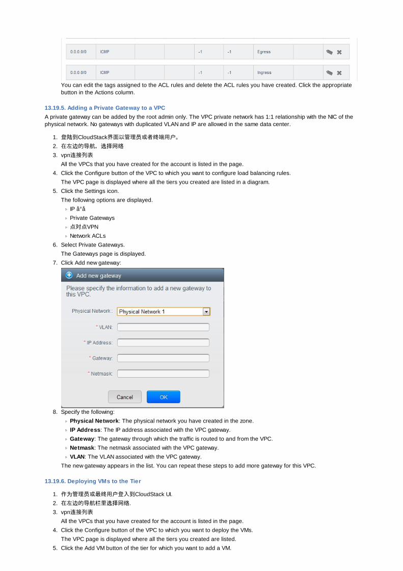
You can edit the tags assigned to the ACL rules and delete the ACL rules you have created. Click the appropriatebutton in the Actions column.
13.19.5. Adding a Private Gateway to a VPCA private gateway can be added by the root admin only. The VPC private network has 1:1 relationship with the NIC of thephysical network. No gateways with duplicated VLAN and IP are allowed in the same data center.
1. 登陆到CloudStack界面以管理员或者终端用户。2. 在左边的导航,选择网络3. vpn连接列表
All the VPCs that you have created for the account is listed in the page.
4. Click the Configure button of the VPC to which you want to configure load balancing rules.
The VPC page is displayed where all the tiers you created are listed in a diagram.
5. Click the Settings icon.
The following options are displayed.
IP å °å Private Gateways
点对点VPN
Network ACLs
6. Select Private Gateways.
The Gateways page is displayed.
7. Click Add new gateway:
8. Specify the following:
Physical Network: The physical network you have created in the zone.
IP Address: The IP address associated with the VPC gateway.
Gateway: The gateway through which the traffic is routed to and from the VPC.
Netmask: The netmask associated with the VPC gateway.
VLAN: The VLAN associated with the VPC gateway.
The new gateway appears in the list. You can repeat these steps to add more gateway for this VPC.
13.19.6. Deploying VMs to the Tier
1. 作为管理员或最终用户登入到CloudStack UI.
2. 在左边的导航栏里选择网络.
3. vpn连接列表All the VPCs that you have created for the account is listed in the page.
4. Click the Configure button of the VPC to which you want to deploy the VMs.
The VPC page is displayed where all the tiers you created are listed.
5. Click the Add VM button of the tier for which you want to add a VM.

The Add Instance page is displayed.
Follow the on-screen instruction to add an instance. For information on adding an instance, see Adding Instancessection in the Installation Guide.
13.19.7. Acquiring a New IP Address for a VPCWhen you acquire an IP address, all IP addresses are allocated to VPC, not to the guest networks within the VPC. The IPsare associated to the guest network only when the first port-forwarding, load balancing, or Static NAT rule is created forthe IP or the network. IP can't be associated to more than one network at a time.
1. 作为管理员或最终用户登入到CloudStack UI.
2. 在左边的导航栏里选择网络.
3. vpn连接列表All the VPCs that you have created for the account is listed in the page.
4. Click the Configure button of the VPC to which you want to deploy the VMs.
The VPC page is displayed where all the tiers you created are listed in a diagram.
5. Click the Settings icon.
The following options are displayed.
IP地址
网关
点对点VPN
Network ACLs
6. Select IP Addresses.
The IP Addresses page is displayed.
7. 点击获得一个新IP, 并且在确认的对话框中点击确定.
You are prompted for confirmation because, typically, IP addresses are a limited resource. Within a few moments,the new IP address should appear with the state Allocated. You can now use the IP address in port forwarding, loadbalancing, and static NAT rules.
13.19.8. Releasing an IP Address Alloted to a VPCThe IP address is a limited resource. If you no longer need a particular IP, you can disassociate it from its VPC and returnit to the pool of available addresses. An IP address can be released from its tier, only when all the networking ( portforwarding, load balancing, or StaticNAT ) rules are removed for this IP address. The released IP address will still belongsto the same VPC.
1. 作为管理员或最终用户登入到CloudStack UI.
2. 在左边的导航栏里选择网络.
3. vpn连接列表All the VPCs that you have created for the account is listed in the page.
4. Click the Configure button of the VPC whose IP you want to release.
The VPC page is displayed where all the tiers you created are listed in a diagram.
5. Click the Settings icon.
The following options are displayed.
IP地址
网关
点对点VPN
Network ACLs
6. Select IP Addresses.
The IP Addresses page is displayed.
7. Click the IP you want to release.
8. In the Details tab, click the Release IP button
13.19.9. Enabling or Disabling Static NAT on a VPCA static NAT rule maps a public IP address to the private IP address of a VM in a VPC to allow Internet traffic to it. Thissection tells how to enable or disable static NAT for a particular IP address in a VPC.
If port forwarding rules are already in effect for an IP address, you cannot enable static NAT to that IP.
If a guest VM is part of more than one network, static NAT rules will function only if they are defined on the default network.
1. 作为管理员或最终用户登入到CloudStack UI.
2. 在左边的导航栏里选择网络.
3. vpn连接列表
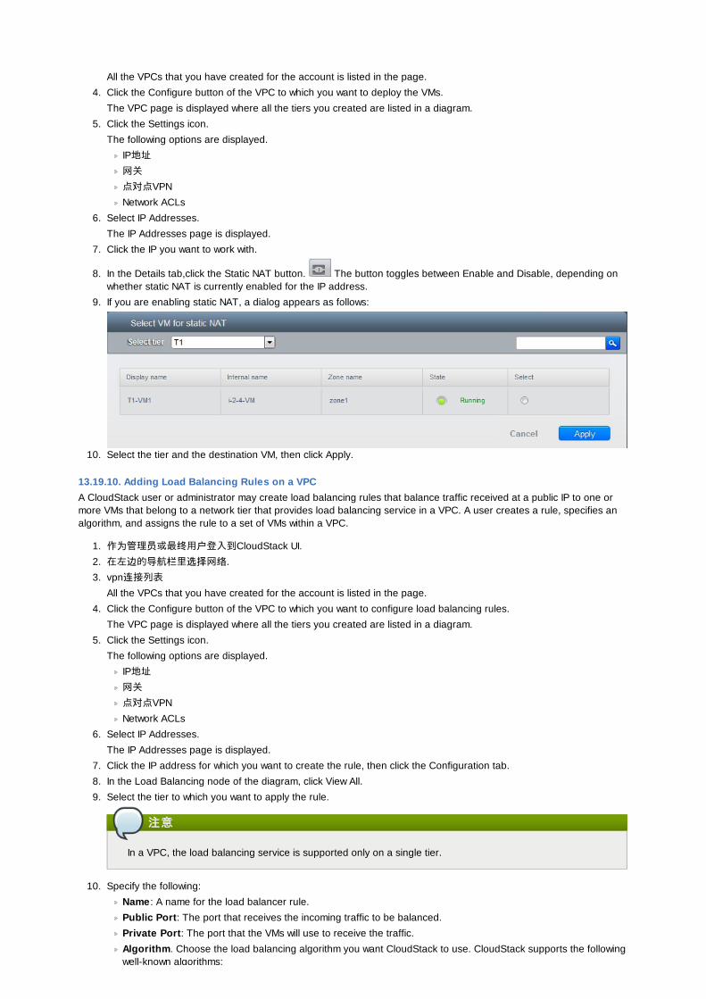
All the VPCs that you have created for the account is listed in the page.
4. Click the Configure button of the VPC to which you want to deploy the VMs.
The VPC page is displayed where all the tiers you created are listed in a diagram.
5. Click the Settings icon.
The following options are displayed.
IP地址
网关
点对点VPN
Network ACLs
6. Select IP Addresses.
The IP Addresses page is displayed.
7. Click the IP you want to work with.
8. In the Details tab,click the Static NAT button. The button toggles between Enable and Disable, depending onwhether static NAT is currently enabled for the IP address.
9. If you are enabling static NAT, a dialog appears as follows:
10. Select the tier and the destination VM, then click Apply.
13.19.10. Adding Load Balancing Rules on a VPCA CloudStack user or administrator may create load balancing rules that balance traffic received at a public IP to one ormore VMs that belong to a network tier that provides load balancing service in a VPC. A user creates a rule, specifies analgorithm, and assigns the rule to a set of VMs within a VPC.
1. 作为管理员或最终用户登入到CloudStack UI.
2. 在左边的导航栏里选择网络.
3. vpn连接列表All the VPCs that you have created for the account is listed in the page.
4. Click the Configure button of the VPC to which you want to configure load balancing rules.
The VPC page is displayed where all the tiers you created are listed in a diagram.
5. Click the Settings icon.
The following options are displayed.
IP地址
网关
点对点VPN
Network ACLs
6. Select IP Addresses.
The IP Addresses page is displayed.
7. Click the IP address for which you want to create the rule, then click the Configuration tab.
8. In the Load Balancing node of the diagram, click View All.
9. Select the tier to which you want to apply the rule.
注意注意
In a VPC, the load balancing service is supported only on a single tier.
10. Specify the following:
Name : A name for the load balancer rule.
Public Port: The port that receives the incoming traffic to be balanced.
Private Port: The port that the VMs will use to receive the traffic.
Algorithm. Choose the load balancing algorithm you want CloudStack to use. CloudStack supports the followingwell-known algorithms:
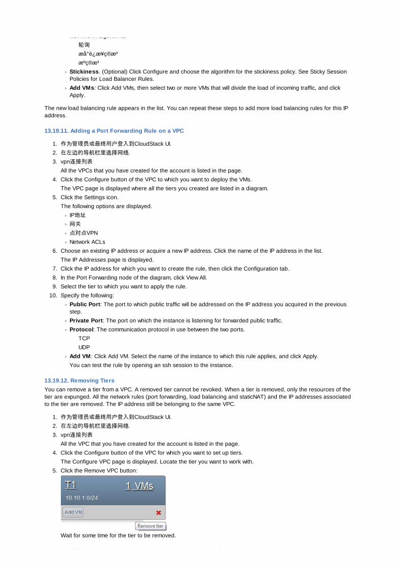
well-known algorithms:
轮询æå° è¿ æ¥ç®æ³ æºç®æ³
Stickiness. (Optional) Click Configure and choose the algorithm for the stickiness policy. See Sticky SessionPolicies for Load Balancer Rules.
Add VMs: Click Add VMs, then select two or more VMs that will divide the load of incoming traffic, and clickApply.
The new load balancing rule appears in the list. You can repeat these steps to add more load balancing rules for this IPaddress.
13.19.11. Adding a Port Forwarding Rule on a VPC
1. 作为管理员或最终用户登入到CloudStack UI.
2. 在左边的导航栏里选择网络.
3. vpn连接列表All the VPCs that you have created for the account is listed in the page.
4. Click the Configure button of the VPC to which you want to deploy the VMs.
The VPC page is displayed where all the tiers you created are listed in a diagram.
5. Click the Settings icon.
The following options are displayed.
IP地址
网关
点对点VPN
Network ACLs
6. Choose an existing IP address or acquire a new IP address. Click the name of the IP address in the list.
The IP Addresses page is displayed.
7. Click the IP address for which you want to create the rule, then click the Configuration tab.
8. In the Port Forwarding node of the diagram, click View All.
9. Select the tier to which you want to apply the rule.
10. Specify the following:
Public Port: The port to which public traffic will be addressed on the IP address you acquired in the previousstep.
Private Port: The port on which the instance is listening for forwarded public traffic.
Protocol: The communication protocol in use between the two ports.
TCP
UDP
Add VM : Click Add VM. Select the name of the instance to which this rule applies, and click Apply.
You can test the rule by opening an ssh session to the instance.
13.19.12. Removing TiersYou can remove a tier from a VPC. A removed tier cannot be revoked. When a tier is removed, only the resources of thetier are expunged. All the network rules (port forwarding, load balancing and staticNAT) and the IP addresses associatedto the tier are removed. The IP address still be belonging to the same VPC.
1. 作为管理员或最终用户登入到CloudStack UI.
2. 在左边的导航栏里选择网络.
3. vpn连接列表All the VPC that you have created for the account is listed in the page.
4. Click the Configure button of the VPC for which you want to set up tiers.
The Configure VPC page is displayed. Locate the tier you want to work with.
5. Click the Remove VPC button:
Wait for some time for the tier to be removed.
13.19.13. Editing, Restarting, and Removing a Virtual Private Cloud
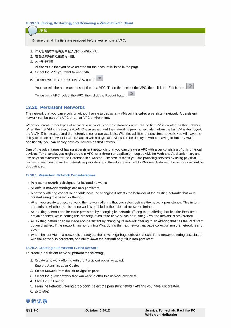
13.19.13. Editing, Restarting, and Removing a Virtual Private Cloud
注意注意
Ensure that all the tiers are removed before you remove a VPC.
1. 作为管理员或最终用户登入到CloudStack UI.
2. 在左边的导航栏里选择网络.
3. vpn连接列表All the VPCs that you have created for the account is listed in the page.
4. Select the VPC you want to work with.
5. To remove, click the Remove VPC button
You can edit the name and description of a VPC. To do that, select the VPC, then click the Edit button.
To restart a VPC, select the VPC, then click the Restart button.
13.20. Persistent NetworksThe network that you can provision without having to deploy any VMs on it is called a persistent network. A persistentnetwork can be part of a VPC or a non-VPC environment.
When you create other types of network, a network is only a database entry until the first VM is created on that network.When the first VM is created, a VLAN ID is assigned and the network is provisioned. Also, when the last VM is destroyed,the VLAN ID is released and the network is no longer available. With the addition of persistent network, you will have theability to create a network in CloudStack in which physical devices can be deployed without having to run any VMs.Additionally, you can deploy physical devices on that network.
One of the advantages of having a persistent network is that you can create a VPC with a tier consisting of only physicaldevices. For example, you might create a VPC for a three-tier application, deploy VMs for Web and Application tier, anduse physical machines for the Database tier. Another use case is that if you are providing services by using physicalhardware, you can define the network as persistent and therefore even if all its VMs are destroyed the services will not bediscontinued.
13.20.1. Persistent Network Considerations
Persistent network is designed for isolated networks.
All default network offerings are non-persistent.
A network offering cannot be editable because changing it affects the behavior of the existing networks that werecreated using this network offering.
When you create a guest network, the network offering that you select defines the network persistence. This in turndepends on whether persistent network is enabled in the selected network offering.
An existing network can be made persistent by changing its network offering to an offering that has the Persistentoption enabled. While setting this property, even if the network has no running VMs, the network is provisioned.
An existing network can be made non-persistent by changing its network offering to an offering that has the Persistentoption disabled. If the network has no running VMs, during the next network garbage collection run the network is shutdown.
When the last VM on a network is destroyed, the network garbage collector checks if the network offering associatedwith the network is persistent, and shuts down the network only if it is non-persistent.
13.20.2. Creating a Persistent Guest NetworkTo create a persistent network, perform the following:
1. Create a network offering with the Persistent option enabled.
See the Administration Guide.
2. Select Network from the left navigation pane.
3. Select the guest network that you want to offer this network service to.
4. Click the Edit button.
5. From the Network Offering drop-down, select the persistent network offering you have just created.
6. 点击 确定。
更新更新记录记录修修订订 1-0 October 5 2012 Jessica Tomechak, Radhika PC,
Wido den Hollander

Initial publication


![CloudStack 管理者ガイド Apache CloudStack 4.1 · Apache CloudStack 4.1.0 CloudStack 管理者ガイド open source cloud computing ™ CloudStack Apache [FAMILY Given]](https://img.pdfslide.net/doc/110x75/5d67a01888c9934b0e8b528b/cloudstack-apache-cloudstack-41-apache-cloudstack-410.jpg)