Embed Size (px)
Citation preview

US008662250B2
(12) Ulllted States Patent (10) Patent N0.: US 8,662,250 B2 Kennedy (45) Date of Patent: *Mar. 4, 2014
(54) STAIR SYSTEM FOR OILFIELD TANK 2,933,149 A 4/1960 Lee 3,067,835 A 8/1960 Valley
. - ~ - 3,047,093 A 7/1962 Cruz (75) Inventor. lglgron Jlm Kennedy, W1ch1ta Falls, TX 4,014,486 A 3/1977 Nelson et a1‘
( ) 4,669,574 A 6/1987 Moutot _ 4,787,111 A 11/1988 Paceket a1.
(73) Ass1gnee: Wichita Tank Manufacturing, Ltd., 5,026,244 A 6/1991 Dorn Wichita Falls, TX (US) 5,027,922 A 7/1991 Benko et a1.
5,064,022 A 11/1991 Graham >8 - . ~ ~ ~ - 5,154,569 A 10/1992 Eryou et a1.
( ) Not1ce. subject'to any ((111s(c1la1me5,thet1ermdofth1s 5,213,367 A 5/l993 Norman’lr‘et a1‘ patent 1s exten e or a Juste un er 35 5,553,990 A 9/1996 Kytola U.S.C. 154(15) by 0 days. 5,845,356 A 12/1998 Kielinski
. . . . . 6,152,492 A 11/2000 Markham et a1. Th1s patent 1s subject to a term1nal d1s- D442 520 S 50001 Wade claimer. 6,279,955 B1 8/2001 Fisher
6,375,222 B1 4/2002 Wade (21) APPLNQ; 13/359,644 6,390,325 B1 5/2002 Gonzales
6,598,704 B2 7/2003 Hansen
(22) Filed: Jan. 27, 2012 (Continued)
(65) Prior Publication Data OTHER PUBLICATIONS
Us 2012/0125713 A1 May 24’ 2012 Dragon Products Ltd, Connecting Catwalk Corrugated Wall Liquid Storage, date of publication is unknown Internet address: http://www. dragonproductsltdcom/tanks/ Related US. Application Data
(63) Continuation-in-part of application No. 12/333,892, fr%20c0rrugated%20wall%20connecting.htm.
?led On Dec. 12, 2008, HOW Pat. NO. 8,113,314. (Continued)
(51) Int CL Primary Examiner * Katherine Mitchell
E04G 3/00 (200601) Assistant Examiner * Johnnie A Shablack
(52) us CL (74) Attorney, Agent, or Firm * James E. Walton; Richard
USPC ............... .. 182/84; 182/82; 182/62.5; 182/95 6 Eldredge
(58) Field of Classi?cation Search USPC ......... .. 182/83, 84, 85, 86, 62.5, 106, 95, 127 (57) ABSTRACT See application ?le for complete search history. A mobile oil?eld storage tank includes a front wall and a
removable stair system coupled thereto. The stair system (56) References Cited includes a platform suitable for use as a walkway and a
platform extension operably associated therewith. The plat form extension creates a continuous walkway between the platform and a platform of an adjacent mobile oil?eld storage
U.S. PATENT DOCUMENTS
31,216 A 1/1861 Sprague 159,571 A 2/1875 Fuchslocher tank 289,726 A 12/1883 Tevis
1,713,730 A 5/1929 Wright 20 Claims, 13 Drawing Sheets
1701 X
1723 f 1703
1711
1721
1705 1707

US 8,662,250 B2 Page 2
(56)
6,981,572 6,986,402 7,004,286 7,025,174 7,140,467 7,296,640 7,516,997 7,762,588 7,775,169 7,832,525
2001/0030081 2004/0159492 2006/0272896
References Cited
U.S. PATENT DOCUMENTS
B2 B2 B2 B1 B2 B2 B2 B2 B2 B2 A1 A1 A1
1/2006 1/2006 2/2006 4/2006 11/2006 11/2007 4/2009 7/2010 8/2010
11/2010 10/2001 8/2004
12/2006
Hedley Hedley et al. Fredette HaWley Cook Tettleton KuZnarik et al. Markham Horn et al. Bennett et al. Morimoto et a1. Hedley et al. Raj eWski
2007/0125598 A1 6/2007 Castagno et al. 2007/0256893 A1 11/2007 Horn et al. 2009/0145692 A1 6/2009 Flickinger et al.
OTHER PUBLICATIONS
Preliminary Amendment ?led in Parent Application No. 12333892 on Dec. 2, 2010.
Non-Final Of?ce Action from Parent Application No. 12333892 dated Jul. 22, 2011. Amendment ?led in Parent Application No. 12333892 dated Nov. 22, 201 1. Examiner Interview Summary from Parent Application No. 12333892 dated Sep. 26, 2011. Notice of Allowance from Parent Application No. 12333892 dated Oct. 19,2011.
US. Patent Mar. 4, 2014 Sheet 1 0f 13 US 8,662,250 B2
100—\
_11O
//" 108
112 114
Fig. 1 (Prior Art)

US. Patent Mar. 4, 2014 Sheet 2 0f 13 US 8,662,250 B2
228 f" 202 f
203
\ '\ 208
Fig. 2a
Fig. 2b
200
X /— 202
Fig. 2c

US. Patent Mar. 4, 2014 Sheet 3 0f 13 US 8,662,250 B2
256 258 264 266 286
284 N O) 00
270
232 v
Fig. 3

US. Patent Mar. 4, 2014 Sheet 4 0f 13 US 8,662,250 B2
236
Fig. 4b

US. Patent Mar. 4, 2014 Sheet 5 0f 13 US 8,662,250 B2
EN wwm
mm .5
wow wow www www wow ohm
wmm www
www
wmm wwm
f 0mm mwm
4/! cow


US. Patent Mar. 4, 2014 Sheet 7 0f 13 US 8,662,250 B2
wmw
W RN / / m8 Alllv $8 @8
wmm
SE29‘ mmm
mom |\
\
wow
/ mg
‘IV 1%
wmm

US. Patent Mar. 4, 2014 Sheet 8 0f 13 US 8,662,250 B2
26E 26E
J 1 m w BQI/
\) ,7
w @ @ @ @ WK @QEI/ @ ? @ “MERE Lu: E: 22 S2 til, a |/. u 22 ;, o @ °\IB: Ira o @O:|\, EKZZ a .. . QISS
82K a; .2 - x a.
/f8€
|8S
K S: K 52

US. Patent Mar. 4, 2014 Sheet 9 0f 13 US 8,662,250 B2
Wv .GE 83 8:‘ l/
l/ l/moi J mzww )3 m3: S3
53
as K‘ /////////A \_ K moor
woo? l\
f

US. Patent Mar. 4, 2014 Sheet 10 0f 13 US 8,662,250 B2
—x 1503
'L 1105 k 1111
FIG. 15
1 1 17 1017 1003
EEZ"; J x 1303 1301
1307 III 2|]
k 1011 XV‘ [111' ‘IF XVI
\JL 1305 1107
FIG. 13


US. Patent Mar. 4, 2014 Sheet 12 0f 13 US 8,662,250 B2
m2. GE 1 101/
182 I //I ////A’/////
\| wow?
Iii
///
it I/
_|||l E u
182 u Sm:
ttiu W k
QEINH 82 \ \ \ \
Rt |\|
:t. R mot‘ R
'I////////////////////////// Ill/Il/l/l/l/N/l'll, / //////I///
\l Pom:

US. Patent Mar. 4, 2014 Sheet 13 0f 13 US 8,662,250 B2
1907 1909
FIG. 198 ////I ////I////////////////
1901 *\
1909-1903 '//////////////I/Il/I/I/I/ Ill/I/I/l/A/l/ll/ lI/I/l II/ l/l/l/
1 \ \\\
1901 \ 1801 —/

US 8,662,250 B2 1
STAIR SYSTEM FOR OILFIELD TANK
CROSS REFERENCE TO RELATED APPLICATIONS
This application is a continuation-in-part of US. applica tion Ser. No. 12/333,892, ?led 12 Dec. 2008, titled “Stair System for Oil?eld Tank,” Which is hereby incorporated by reference for all purposes as if fully set forth herein.
BACKGROUND
1. Field of the Invention The present application relates generally to mobile storage
tanks, and more speci?cally, to a mobile storage tank having a removably stair system.
2. Description of Related Art Stair systems for mobile oil?eld tanks are provided With a
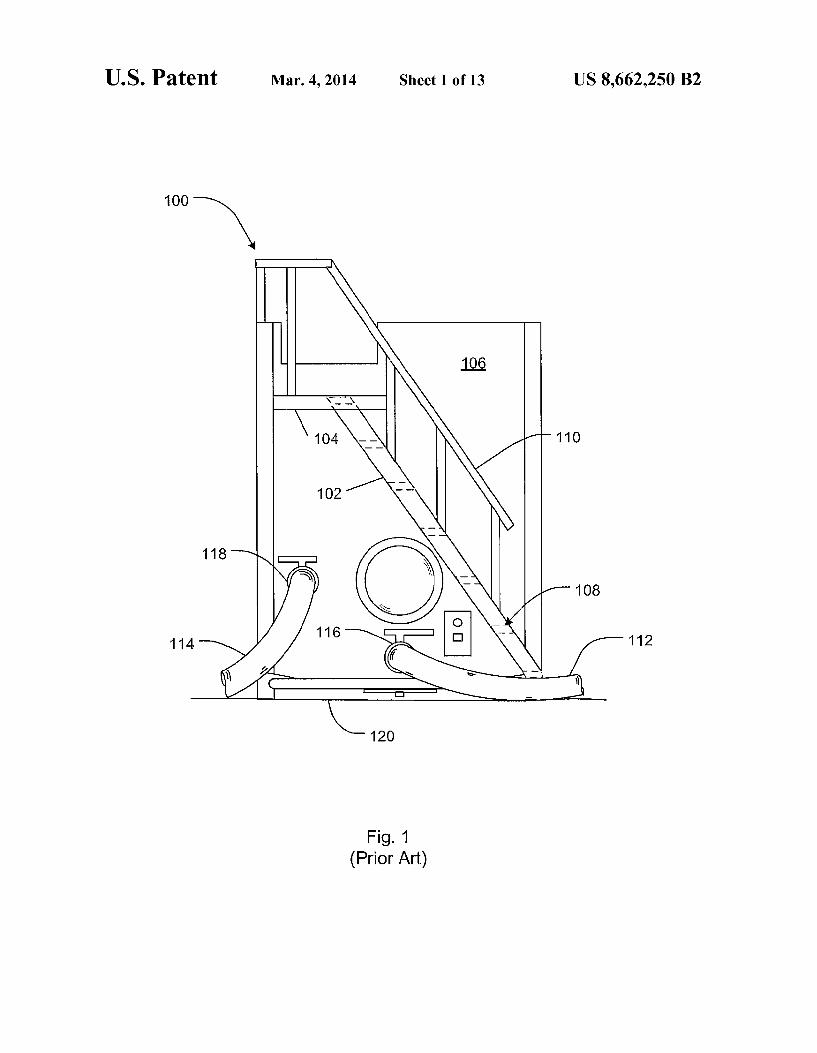
staircase attached to a platform for access to the top surface of the tank. FIG. 1 shoWs a conventional stair system 100 having a staircase 102 and a platform 104 attached to a Wall surface 106. Staircase 102 carries a plurality of stairs 108 and a hand rail 110 for providing support and security as the Worker climbs staircase 102. It should be understood that stair system 100 rigidly attaches to the storage tank, Which can require signi?cant time and cost associated With the painting process and during the process of removing a damaged stair system.
During operation, a plurality of oil?eld tanks are posi tioned side-by-side and joined together With one or more tubing netWorks to create a large reservoir for storing and dispensing liquids such as fracturing ?uids, drilling mud, crude oil, and various other liquids or slurries. A Well-knoWn problem With the conventional stair system is that the Worker must climb and descend each staircase to get from one tank to
another; and, the Worker must step over tubing, manifolds, and other devices operably associated With the oil?eld tanks, Which can be a time consuming and dangerous process. For example, FIG. 1 shoWs tubing 112, 114 attached to valves 116, 118, respectively. Tubing 112, 114 are shoWn lying on ground 120 and exposed to rain, ice, snoW, or ?uids stored or dispensed by the oil?eld tank. The tubing could be caked With mud or other slippery substances. Tubing also has a propen sity to move With pressure ?uctuations. A Worker could easily trip on the tubing, manifolds, and other devices When travel ing betWeen stair systems.
Although the foregoing developments represent great strides in the area of mobile storage tanks, many shortcom ings remain.
DESCRIPTION OF THE DRAWINGS
The novel features believed characteristic of the system are set forth in the appended claims. HoWever, the system itself, as Well as a preferred mode of use, and further objectives and advantages thereof, Will best be understood by reference to the folloWing detailed description When read in conjunction With the accompanying draWings, Wherein:
FIG. 1 is a front vieW of a conventional stair system for a mobile storage tank;
FIG. 2a is a side vieW of a stair system for a mobile storage tank according to the preferred embodiment Wherein the stair system is shoWn in extended mode;
FIG. 2b is a side vieW of a stair system for a mobile storage tank according to the preferred embodiment Wherein the stair system is shoWn in retracted mode;
20
25
30
35
40
45
50
55
60
65
2 FIG. 20 is a side vieW of a stair system for a mobile storage
tank according to the preferred embodiment Wherein the stair system is shoWn in retracted mode;
FIG. 3 is an oblique vieW of a stair system for a mobile storage tank according to the preferred embodiment;
FIGS. 4a and 4b are oblique vieWs of a platform subsystem shoWn in FIG. 2;
FIGS. 5a and 5b are side vieWs of the stair system shoWn in FIG. 2;
FIG. 6 is a front vieW of multiple stair systems according to the preferred embodiment;
FIG. 7 is a block diagram shoWing an actuator for extend ing and retracting a retractable platform extension;
FIG. 8 is a block diagram shoWing an actuator for extend ing and retracting a staircase;
FIG. 9 is a side vieW of an embodiment of the platform subsystem con?gured for rigidly attaching to a neighboring platform subsystem;
FIG. 10 is a front vieW of a removable stair system; FIG. 11 is a front vieW of a mobile storage tank; FIG. 12 is a front vieW of the removable stair system of
FIG. 10 securely coupled to the mobile storage tank of FIG. 11;
FIG. 13 is a side vieW of a portion of the removable stair system of FIG. 10 taken at XIII-XIII;
FIG. 14 is a cross-sectional side vieW of a portion of the removable stair system of FIG. 10 taken at XIV-XIV;
FIG. 15 is a cross-sectional side vieW of a portion of the removable stair system of FIG. 10 taken at XV-XV;
FIG. 16 is a cross-sectional vieW of a portion of the remov able stair system of FIG. 13 taken at XVI-XVI;
FIGS. 17A and 17B are front vieWs of the mobile storage tank and the removable stair system of FIG. 12;
FIGS. 18A and 18B are side vieWs of a stair system and mobile tank according to an alternative embodiment of the present application; and
FIGS. 19A and 19B are side vieWs of a stair system and mobile tank according to an alternative embodiment of the present application.
While the system and method of the present application is susceptible to various modi?cations and alternative forms, speci?c embodiments thereof have been shoWn by Way of example in the draWings and are herein described in detail. It should be understood, hoWever, that the description herein of speci?c embodiments is not intended to limit the invention to the particular embodiment disclosed, but on the contrary, the intention is to cover all modi?cations, equivalents, and alter natives falling Within the spirit and scope of the process of the present application as de?ned by the appended claims.
DETAILED DESCRIPTION OF THE PREFERRED EMBODIMENT
Illustrative embodiments are described beloW. In the inter est of clarity, not all features of an actual implementation are described in this speci?cation. It Will of course be appreciated that in the development of any such actual embodiment, numerous implementation-speci?c decisions Will be made to achieve the developer’s speci?c goals, such as compliance With system-related and business-related constraints, Which Will vary from one implementation to another. Moreover, it Will be appreciated that such a development effort might be complex and time-consuming but Would nevertheless be a routine undertaking for those of ordinary skill in the art hav ing the bene?t of this disclosure. The system of the present application overcomes common
disadvantages associated With knoWn mobile storage tanks

US 8,662,250 B2 3
having rigidly attached stair systems. Speci?cally, one of the unique features of the mobile tank system is a removable stair system detachably coupled to the storage tank. This feature provides signi?cant advantages, namely, the stair system is easily and rapidly removed from the tank, resulting in less time exhausted during both the painting process and replace ment of a damaged stair system. Further detailed description of these features are provided beloW and illustration in the accompanying draWings.
The system Will be understood, both as to its structure and operation, from the accompanying draWings, taken in con junction With the accompanying description. Several embodi ments of the system are presented herein. It should be under stood that various components, parts, and features of the different embodiments may be combined together and/or interchanged With one another, all of Which are Within the scope of the present application, even though not all varia tions and particular embodiments are shoWn in the draWings. It should also be understood that the mixing and matching of features, elements, and/ or functions betWeen various embodi ments is expressly contemplated herein so that one of ordi nary skill in the art Would appreciate from this disclosure that the features, elements, and/ or functions of one embodiment may be incorporated into another embodiment as appropriate, unless described otherWise.
Referring noW to the draWings Wherein like reference char acters identify corresponding or similar elements throughout the several vieWs, FIGS. 2a-c illustrate side vieWs of a stair system 200 for an oil?eld tank 202 according to the preferred embodiment are illustrated. FIGS. 2a, 2b, and 2c depict stair system 200 in extended and retracted, respectively. FIG. 2a shoWs staircase subsystem 232 and rail subsystem 230 in an extended position. This position provides a Worker (not shoWn) access to a top surface 204 of oil?eld tank 202. FIG. 2b shoWs staircase subsystem 232 and rail subsystem 230 in a folded position. In this position, stair system 200 is either being prepared for transit, storage, or interlinked betWeen oil?eld tanks, Wherein only platform subsystem 228 is opera tional. For example, FIG. 6 in the draWings shoWs stair sys tem 200 in a folded position. In this con?guration, platform subsystem 228 forms a WalkWay along oil?eld tanks 202A, 202B, and 202C. FIG. 20 illustrates stair system 200 in a folded position and oil?eld tank 202 hitched to a tractor 201. In this position, stair system 200 is prepared for transit.
In the preferred embodiment, stair system 200 attaches to an oil?eld tank 202. It should be understood that the stair system could attach to alternative surfaces, and should not be limited to oil?eld tanks. For example, the stair system could attach to various types of mobile tanks, vehicles, buildings, and other similar objects or devices. In the preferred embodi ment, members of stair system 200 are composed of rigid metallic materials, but it should be appreciated that alterna tive embodiments could include members composed of dif ferent material. For example, stair system 200 could include members composed of plastic, Wood, composite, and other suitable materials.
FIG. 2a shoWs oil?eld tank 202 having a rear surface 203, top surface 204, a bottom surface 206, a front surface 208, and a side surface 210. In addition, oil?eld tank 202 has a side surface 600, as shoWn in FIG. 6. In the preferred embodiment, stair system 200 rigidly attaches to front surface 208, but could be attached to a rear or side surface in alternative embodiments.
Referring noW to FIG. 3 in the draWings, an oblique vieW of stair system 200 according to the preferred embodiment is illustrated. Front surface 208 is shoWn carrying pipes 212, 214, 216, and 218. Pipes 212, 214, 216 and 218 extend
20
25
30
35
40
45
50
55
60
65
4 through front surface 208 and enter into one or more cham bers (not shoWn) carried by oil?eld tank 202. The pipes pro vide ?uid passage for fracturing ?uids, drilling mud, crude oil and various other liquids or slurries. In the preferred embodi ment, pipes 212, 214, 216 include manually operated valves 220, 222, and 224, respectively, for opening and closing the passage. In alternative embodiments, valves 220, 222, and 224 may include an actuator for opening and closing the passage. Tubing, as shoWn in FIG. 6, are coupled to pipe 216 for joining multiple oil?eld tanks. In the preferred embodi ment, pipe 216 is con?gured to direct ?uid ?oW parallel to front surface 208. This con?guration enables a Worker to more easily attach tubing to adjacent oil?eld tanks, hoWever, in an alternative embodiment, pipe 216 could be designed With a con?guration similar to pipes 212, 214. Pipe caps 225, 226, 227 are placed on pipe 212, 214, 216, respectively When the pipes are not being used. The pipe caps prevent unWanted materials from entering into the pipe during transit or storage. Horizontal support members 205, 207 attach to bottom sur face 206. A vertical support member 209 is shoWn attached to horiZontal support member 207. Vertical support member 209 attaches to pipe 216 for providing additional support and rigidity.
Stair system 200 comprises a unique combination of a foldable staircase and an extendable platform. In the pre ferred embodiment, stair system 200 includes platform sub system 228, rail subsystem 230, and staircase subsystem 232. Platform subsystem 228 comprises a platform 234 and a retractable platform extension 236.As shoWn, platform 234 is attached to front surface 208 and is supported by tWo sup porting frames 238, 240. The unique features of platform subsystem 228 are more fully discussed With reference to FIGS. 4a and 4b in the draWings. TWo guard rails 242, 243 vertically attach to platform subsystem 228 for providing rigidity and security for a Worker traversing platform sub system 228. Optional stiffening support 244 attaches to guard rail 242 for additional rigidity. In the preferred embodiment, a covered surface 246 is composed of a metallic material and attaches to guard rail 242. Surface 246 provides additional rigidity and can be con?gured to include logos, numbers, Warning signs, and other similar messages. In alternative embodiments, surface 246 may be attached to guard rail 242 by various fastening means. For example, surface 246 could be attached With magnets, ?anges, tabs, connection devices, or other similar devices. In addition, surface 246 could be composed of alternative materials, such as plastic, composite, Wood, or a combination thereof.
In some embodiments, the stair system 200 can include a removable barrier for at least partially blocking unprotected edges of the WalkWay. For example, chains 248, 250 can be used as such removable barriers. Chains 248, 250 are shoWn attached to guard rails 242, 243, respectively. Chain 248 includes a connection device 249 Which couples to loop 251 When retractable platform extension 236 is not being used, and to a loop 252 of a similar adjacent stair system When retractable platform extension 236 is being used. Chain 250 attaches to loop 251 of a similar adjacent stair system When the retractable platform extension of that stair system is extended. The stair system 200 can also include platform securing means for securing the retractable platform exten sion 236 in a retracted or extended position. For example, the retractable platform extension 236 can be secured using a chain 253. Chain 253 attaches to guard rail 242 and carries a loop 255 and a connection device 257. A Worker may secure retractable platform extension 236 by Wrapping chain 253 around grip handle 254 and connecting connection device 257 to loop 255, as shoWn in FIG. 4b. In alternative embodi

US 8,662,250 B2 5
ments, the platform securing means can include various other connection devices and loops, fastening means, such as mag nets, ?anges, tabs, or other connection devices.
In the preferred embodiment, stair system 200 incorporates chains 248, and 250 as removable barriers and chain 253 as a platform securing means, but it should be understood that alternative embodiments could include rope, Wire, or other suitable materials in lieu of chains. In addition, alternative embodiments could replace chains 248, 250 With a rigid support member. For example, an alternative embodiment could incorporate a rigid removable or retractable barrier, such as a beam or rod that telescopes, slides, or pivots on stair system 200 or a surface of oil?eld tank 202 for extending to another similar adjacent stair system. An example of a rigid retractable barrier Would be a gate that pivotally attaches to the guard rail for pivotal rotation to a position substantially parallel to the front surface When the platform system is being used, and for pivotal rotation to a position substantially per pendicular to the front surface When the platform system is not being used. The rigid removable barrier provides addi tional support and security as a Worker uses the platform subsystem.
Rail subsystem 230 includes tWo vertical supports 256, 258, tWo ?rst hand rail members 260, 262, tWo second hand rail members 264, 266, and tWo moveable supports 268, 270. In alternative embodiments, stair system 200 can be designed Without a rail subsystem or With a rail subsystem With one hand rail. In the preferred embodiment, members of the rail subsystem 230 fold When stair system 200 is in retracted mode, as shoWn in FIGS. 2b, 20, 5a and 6 in the draWings. Vertical supports 256, 258 are supported by horiZontal sup ports 272, 274 and staircase subsystem 232. First hand rail members 260, 262 rigidly attach to vertical supports 256, 258, respectively. In addition, ?rst hand rail members 260, 262 attach to guard rail 242, 243 for additional rigidity and sup port. Second hand rail members 264, 266 are pivotally coupled to ?rst hand rail members 260, 262 With pivot joints 276, 278. Pivot joints 276, 278 enable second hand rail mem bers 264, 266 to fold to a position substantially parallel and alongside vertical support 256, 258 and enable pivotally rota tion to a position substantially parallel and longitudinal to the ?rst hand rail members 260, 262 during retracted mode.
Moveable supports 268, 270 pivotally attach to vertical supports 256, 258 With pivot joints 280, 282, respectively. Moveable supports 268, 270 provide additional support and rigidity for second hand rail members 264, 266. Pivot joints 280, 282 enable moveable supports 268, 270 to pivotally rotate to a position substantially parallel and alongside verti cal support 256, 258 during retracted mode and enable pivotal rotation to a position substantially perpendicular to second hand rail members 260, 262 during extended mode. TWo locking devices 284, 286 attach to distal ends of moveable supports 268, 270, respectively, for locking moveable sup ports 268, 270 to second hand rail members 264, 266. Secur ing devices 288 attaches to vertical support 258 and secures moveable supports 270 and second hand rail member 266 to a position substantially parallel to vertical supports 258. In alternative embodiments, the second hand rail members could telescope or slide Within or alongside the ?rst hand rail members. In addition, alternative embodiments could include gripping grooves or other means for providing friction, trac tion, and gripping operably associated With the rail members. For example, the rail members may include grip tape, a knurled surface treatment, or be embossed or engraved With various surface treatments, textures, or patterns.
In the preferred embodiment, second hand rail members 264, 266 are manually rotated; hoWever, it should be appre
20
25
30
35
40
45
50
55
60
65
6 ciated that in alternative embodiments, rail subsystem 230 could include an actuator that rotates second hand rail mem bers 264, 266 to a position substantially parallel to vertical supports 256, 258, respectively. For example, the actuator could be a pneumatic, hydraulic, motor, spring, or similar device that attaches to the second hand rail and an operably associated member of stair system 200 or a surface of oil?eld tank 202.
Staircase subsystem 232 comprises a ?rst staircase mem ber 292 and a second staircase member 294, each staircase member carrying a plurality of stairs 296. In the preferred embodiment, stairs 296 are composed of grip strut for added traction as a Worker climbs and descends staircase subsystem 232. It should be understood that a myriad of gratings or non-slip materials could be used in lieu of the preferred mate rials. For example, the grip strut could be replaced With bar grating or material that is embossed or engraved With various surface treatments, textures, or patterns.
In the preferred embodiment, ?rst staircase member 292 is rigidly attached to platform subsystem 228 and pivotally attached to second staircase member 294 With pivot joints 296, 298. Pivot joints 296, 298 enable pivotal rotation of second staircase member 294 to a position substantially par allel and above the ?rst staircase member 292 during retracted mode and enable pivotal rotation to a position substantially parallel and longitudinal to ?rst staircase member 292 during extended mode. As shoWn in FIG. 8, alternative embodiments of staircase subsystem 232 could include an actuator 293 that rotates second staircase member 294 about pivot 298. Actua tor 293 could be a pneumatic, hydraulic, motor, spring, or any suitable device. In addition, alternative embodiments may include a second staircase member that telescopes or slides Within or alongside the ?rst staircase member.
Referring noW to FIGS. 4a and 4b in the draWings, oblique vieWs of platform subsystem 228 of FIG. 3 are illustrated. Platform subsystem 228 comprises platform 234 and retract able platform extension 236. A grip handle 254 attaches to retractable platform extension 236. FIG. 4a depicts retract able platform extension 236 in an extended position, While FIG. 4b depicts retractable platform extension 236 in a retracted position. As shoWn in FIG. 6, an extended position is desired When creating a WalkWay betWeen multiple adja cent oil?eld tanks. In the preferred embodiment, platform 234 is composed of grip strut, While retractable platform exten sion 236 is composed of bar grating. It should be understood that platform 234 and retractable platform extension 236 could be composed of various material for increasing traction and for enabling materials, i.e., mud and Water, to pass through the surface. In addition, grip strut and bar grating could be replaced With material that is embossed or engraved With various surface treatments, textures, or patterns. In the preferred embodiment, bar grating is particularly desired for the retractable platform extension because the grating does not have the grip strut’s saW-toothed edges, Which could cause problems When extending and retracting the retractable platform extension. It should also be understood that a remov able platform extension could be used With or in lieu of platform extension 236. For example, the removable platform could be a Wooden beam or any suitable device that extends from one platform system toWards another.
In the preferred embodiment, platform 234 is positioned above retractable platform extension 236, and platform extension 236 slides on support 238 and other supports (not shoWn) located beloW platform 234. A stopper (not shoWn) is attached to the bottom of platform 234 to restrict the distance that retractable platform extension 236 may be extended. In alternative embodiments, retractable platform extension 236

US 8,662,250 B2 7
could be positioned above platform 234. In addition, alterna tive embodiments could pivot retractable platform extension 236 about a device that attaches to platform subsystem 228 or a surface of oil?eld tank 202. It should be appreciated that alternative embodiments could include a retractable platform extension that retracts and extends on both sides to the plat form subsystem. In addition, alternative embodiments could include a retractable platform extension that extends the entire length of the platform.
In the preferred embodiment, retractable platform exten sion 236 is manually extended and retracted; hoWever, it should be appreciated that in alternative embodiments, plat form subsystem 228 could include an actuator 235 that extends and retracts retractable platform extension 236. As shoWn in FIG. 7 in the drawings, a block diagram shoWs that actuator 235 operably associates With platform subsystem 228. Actuator 235 could be a pneumatic, hydraulic, motor, spring, or a similar device that is coupled to the retractable platform extension and an operably associated member of stair system 200 or a surface of oil?eld tank 202. To manually extend retractable platform extension 236, a Worker can pull grip handle 254 in a directionparallel and aWay fromplatform 234. Grip handle 254 is designed to protect the Worker’s hands from coming in contact With support 238 or any other member of stair system 200 or a surface of oil?eld tank 202. As shoWn, platform subsystem 228 includes a chain 253
for securing retractable platform extension 236 in the retracted position. Chain 253 has a connection device 257 and a loop 255. FIG. 4b shoWs chain 253 Wrapped around grip handle 254 and connection device 257 attached to loop 255. In alternative embodiments, a quick-connect type of attach ment, such as a tWist lock fastener or a snap ?t fastener could be used in lieu of connection device 257 and 255. For example, FIG. 9 shoWs an alternative embodiment. In FIG. 9, bracket 237 rigidly attaches to platform extension 236 and couples With a connection device 239. It should be under stood that bracket 237 and connection device 239 are not alWays aligned. Platform extension 236 is capable of pivoting on a pivoting device (not shoWn) to align bracket 237 With connection device 239. In addition, platform extension 236 may pivot due to loW tolerances betWeen the interface of platform 234 and platform extension 236. As depicted, piv otal rotation is shoWn With arroW D1. In the preferred embodi ment, chain 253 is a chain, but it should be understood that alternative embodiments could include rope, Wire, or other suitable materials in lieu of a chain.
Referring noW to FIGS. 5a and 5b in the draWings, side vieWs of stair system 200 are illustrated. FIG. 5a depicts the preferred embodiment of staircase subsystem 232 and rail subsystem 230 in a folded position. In this position, second staircase member 294 is positioned substantially parallel and above ?rst staircase member 292. A locking device (not shoWn) could be used to secure second staircase member 294 in this position. In the preferred embodiment, second hand rail member 266 and moveable support 270 are positioned substantially vertical and alongside vertical support 258 and secured in this position With chain 288. FIG. 5b depicts the preferred embodiment of staircase subsystem 232 and rail subsystem 230 in the folded position With dashed lines and in the extended position With solid lines. To achieve the extended position, second staircase member 294 is pivotally rotated on pivot 298 as shoWn With arroW A; second hand rail member 266 is pivotally rotated on pivot 278 as shoWn With arroW B; and, moveable support 270 is pivotally rotated on pivot 282 as shoWn With arroW C. In this position, moveable support 270 couples With second hand rail member 266 With locking device 286. In the preferred embodiment locking
20
25
30
35
40
45
50
55
60
65
8 device 286 is a metal channel, but it should be appreciated that locking device 286 may be any suitable device for securing second rail handle in an extended position.
Referring noW to FIG. 6 in the draWings, front vieWs of multiple oil?eld tanks 202 With stair systems 200 according to the preferred embodiment are illustrated. As shoWn, an oil?eld tank 202A is positioned adjacent to an oil?eld tank 202B and oil?eld tank 202B is positioned adjacent to an oil?eld tank 202C. It should be understood that FIG. 6 is a simple depiction of three oil?eld tanks; Whereas, the number of oil?eld tanks used in a single operation could increase up to a hundred or more. As explained, the oil?eld tanks are posi tioned side-by-side and joined together With tubing to create a large reservoir for storing and dispensing liquid. As shoWn, tubing 602, 604 are coupled to one end of pipes 216 of oil?eld tanks 202A and 202B, 202B and 202C, respectively. Tubing 606 is coupled to one end ofpipe 216 ofoil?eld tank 202C and could be attached to other pipes or devices (not shoWn) oper ably associated With the oil?eld operation. As shoWn, one end ofpipe 216 ofoil?eld tank 202A is capped With pipe cap 226. Additional tubing could be used to interlink pipes 212, 214 betWeen the oil?eld tanks (not shoWn).
Staircase subsystem 232 and rail subsystem 230 are shoWn in the extended position on oil?eld tank 202A and oil?eld tank 202C and in the folded position on oil?eld tank 202B. Oil?eld tanks 202A and 202C shoW staircase subsystem 232 and rail subsystem 230 in extended mode, While oil?eld tank 202B shoWs the subsystems in retracted mode. It should be understood that the stair system on oil?eld tank 202B could be con?gured in extended mode. For example, as the number of oil?eld tanks increase, more stair systems Will be con?g ured in extended mode so a Worker is not required to Walk the entire length of the WalkWay before descending. Retractable platform extension 236 is shoWn in the extended position on oil?eld tank 202A and oil?eld tank 202B and in the retracted position on oil?eld tank 202C. As shoWn on oil?eld tank 202C, chain 253 secures retractable platform extension 23 6 to support member 238. When extended, retractable platform extension 236 is secured With chain 608 by looping around grip handle 254 and support member 240. In this con?gura tion, a WalkWay is formedbetWeen oil?eldtanks 202A, 202B, and 202C. Chains 248, 250 are shoWn connected to guard rails 242, 243, respectively for added security as a Worker traverses the WalkWay. This con?guration enables a Worker to climb the staircase subsystem 232 of oil?eld tank 202A, traverse the WalkWay and descend staircase subsystem 232 of oil?eld tank 202C. Hence, the danger of tripping on tubing, manifolds and other devices betWeen oil?eld tanks is miti gated. In addition, a Worker no longer is required to climb and descend each stair system to access the top surface of each oil?eld tank. Therefore, this con?guration overcomes the problems associated With a conventional stair system for a mobile storage tank.
Referring next to FIGS. 10-12 in the draWings, Wherein like reference characters identify corresponding or similar elements throughout the several vieWs, front vieWs of an alternative embodiment of the stair systems discussed above are provided. FIG. 1 0 is a simpli?ed front vieW of a removable stair system 1001; FIG. 11 is a simpli?ed front vieW of a mobile storage tank 1101; and FIG. 12 is a front vieW of stair system 1001 secured to tank 1101. When combined, stair system 1001 and tank 1101 create a mobile storage tank system 1201. One of the unique characteristics of tank system 1201
includes the feature of removing stair system 1001 from tank 1101, Which provides signi?cant advantages over knoWn stair systems. For example, prior to use, federal regulations require

US 8,662,250 B2 9
the stair systems to be painted yellow for safety; Whereas, the tank itself is generally painted in a different color, e.g., green or red, resulting in extensive time and effort preparing the stair system for painting. The tank system of the present application overcomes these problems by painting the stair system and the tank separately. This novel feature reduces time and effort exhausted in the painting process.
Furthermore, a removable stair system facilitates rapid replacement of a damaged stair system. For example, a tractor backs into the ladder or staircase of the stair system, Which in turn damages the stair system such that the system is unus able, resulting in the stair system requiring replacement. Con ventional methods include the arduous process of grinding the Welded stair system from the tank, then subsequently Welding a neW stair system to the tank. Further detailed description of these features are provided beloW and illus trated in the accompanying draWings.
Referring speci?cally to FIG. 10, a front vieW of stair system 1001 is shoWn. Stair system 1001 is substantially similar in form and function to the stair systems discussed above, and it Will be appreciated that the features discussed herein are hereby incorporated in tank system 1201, and vice-versa.
Like stair system 200, stair system 1001 includes a plat form 1003 for use as a WalkWay and an operably associated platform extension 1005 for extending the WalkWay to a stair system of an adjacent storage tank (see FIG. 6). Stair system 1001 is further provided With a staircase 1007 for providing climbing access to platform 1003. A support system 1009 is utiliZed as means for securing
stair system 1001 to tank 1101. Support system 1009 prefer ably includes a ?rst platform support 1011 and a second platform support 1013. Both platform supports 1011 and 1013 are rigidly attached to a loWer surface of platform 1003 and are con?gured to provide rigidity and support to platform 1003 as stair system 1001 is coupled to tank 1101.
Both ?rst and second platform supports 1011 and 1013 include an attachment means 1015 for securing stair system 1001 to tank 1101. In the preferred embodiment, attachment means 1015 includes a plurality of holes 1017 for receiving one or more fasteners, e.g., bolts. HoWever, it is contemplated having different attachment means for securing stair system 1001 to tank 1101 in lieu of the preferred embodiment. Also, in the preferred embodiment, supports 1011 and 1013 are Welded to platform 1003; hoWever, it should be appreciated that supports 1011 and 1013 could be attached in any con ventional manner knoWn to one of ordinary skill in the art.
Support system 1009 also includes a ?rst staircase support 1401 and a second staircase support 1403 for providing addi tional rigidity and support to a ladder, staircase, and/ or other suitable climbing means operably associated With stair sys tem 1001. Staircase support 1401 rigidly attaches to both platform 1003 and upper staircase member 1409 of staircase 1007, While support 1403 rigidly attaches to member 1409 and is detachably coupled to tank 1101 (see FIG. 14).
In FIG. 11, a mounting system 1103 is shoWn rigidly attached to a front Wall 1105 of tank 1101. Mounting system 1103 is con?gured to secure stair system 1001 to tank 1101 via support system 1009. In the preferred embodiment, mounting system 1103 includes three platform mounts, spe ci?cally, a ?rst mount 1107 for receiving platform support 1011, a second mount 1109 for receiving platform support 1013, and a third mount 1111 for providing additional resting support as the stair system 1001 is placed thereupon (see FIG. 15).
Mounting system 1103 further comprises means for pro viding additional support and rigidity to staircase 1007. Spe
20
25
30
35
40
45
50
55
60
65
10 ci?cally, mounting system 1103 includes a ?rst staircase mount 1113 for receiving second staircase support 1403 and a second staircase mount 1115 for receiving an additional staircase support similar to support 1403. The preferred pro cess includes coupling staircase supports 1403 to staircase mounts 1113 and 1115 With a plurality of bolts; hoWever, any conventional attachment means knoWn to a person skilled in the art can be used in lieu of bolts.
First and second mounts 1107 and 1109 include one or more holes 1117 that align With holes 1017 of attachment means 1015. During assembly, a forklift elevates and subse quently rests stair system 1001 on mount 1111, Which in turn is secured thereto With a plurality of bolts. Thereafter, ?rst and second supports 1011 and 1013 are coupled to respective mounts 1107 and 1109. Lastly, staircase supports 1403 are coupled to mounts 1113 and 1115.
FIG. 13-16 depict various front and cross-sectional vieWs oftank system 1201. In FIG. 13, a front vieW of support 1011 is shoWn coupled to mount 1107. A plurality of fasteners 1301, for example, bolts, are used to securely couple support 1011 to mount 1107. Support 1011 includes a ?rst support member 1303 rigidly attached to platform 1003, a second member 1305 rigidly attached to member 1303, and a third member 1307 rigidly attached to both members 1303 and 1305. In the preferred embodiment, ?rst support member 1303 forms a right angle relative to second member 1305, thus creating a relative level platform that extends in a direc tion normal to front Wall 1105.
In FIG. 14, a side vieW of support system 1009 is shoWn With staircase 1007. In the preferred embodiment, staircase support 1403 includes a ?rst section 1405 coupled to a second section 1407 via a bolt 1411. It is contemplated having second section 1407 rigidly attached to upper section 1409 of stair case 1007 and detachably coupled to ?rst section 1405 of staircase support 1403. First section 1405 couples to section 1407 at one end and couples to staircase mount 1113 at the opposing end. Staircase mount 1113 includes a horizontal member 1413 used to securely attach ?rst section 1405 thereto via one or more bolts 1415. In an alternative embodi
ment, support 1403 couldbe manufactured as a single support member, in lieu of sectional components, Which attaches directly to staircase mount 1113.
FIG. 15 depicts a side vieW of mount 1111 coupled to platform 1003. In the preferred embodiment, mount 1111 includes a ?rst relatively horiZontal member 1501 that couples to platform 1003, a second member 1503 rigidly attached to both ?rst member 1501 and front Wall 1105 of tank 1101, and a third member 1505 rigidly attached to both ?rst member 1501 and second member 1503. A mounting bracket 1507 rigidly attaches to platform 1003 and includes an attachment means 1509, e.g., a plurality of holes for receiving a plurality of fasteners 1511.
FIG. 16 shoWs a top cross-sectional vieW of platform sup port 1011 and platform mount 1107 of FIG. 13 taken at XVI-XVI. Tank 1101 includes a surface 1601 oriented at an angle relative to front Wall 1105. Surface 1601 provides access to fasteners 1603 that couple support 1011 to mount 1107. In the preferred embodiment, a member 1605 rigidly attaches to surface 1601 and platform mount 1107 for pro viding additional rigidity thereto. It is contemplated Welding both mount 1107 and member 1605 to tank 1101 and bolting platform support 1107 thereto.
Referring next to FIGS. 17A and 17B in the draWings, front vieWs of an alternative embodiment of tank system 1201 are shoWn. Tank system 1701 is substantially similar in form and function to the one or more of the stair systems discussed


![Ulllted States Patent [19] [11] Patent Number: 5,970,479 · PDF fileUlllted States Patent [19] [11] Patent Number: 5,970,479 ... “The Game of Professional Investment is Intolerably](https://img.pdfslide.net/doc/110x75/5a7f2d0e7f8b9aee018b58f6/ulllted-states-patent-19-11-patent-number-5970479-states-patent-19-11.jpg)
![Ulllted States Patent [19] [11] Patent Number: 5,932,342€¦ · US005932342A Ulllted States Patent [19] [11] Patent Number: 5,932,342 Zeira et al. [45] Date of Patent: Aug. 3, 1999](https://img.pdfslide.net/doc/110x75/605be6553bed1b6a777c1449/ulllted-states-patent-19-11-patent-number-5932342-us005932342a-ulllted-states.jpg)

![(12) Ulllted States Patent (10) Patent N0.: US 7,705,177 ... · US007705177B2 (12) Ulllted States Patent (10) Patent N0.: US 7,705,177 B2 Oniciu et a]. (45) Date of Patent: Apr. 27,](https://img.pdfslide.net/doc/110x75/60b0c9a58b545159f300a441/12-ulllted-states-patent-10-patent-n0-us-7705177-us007705177b2-12.jpg)


![Ulllted States Patent [19] [11] Patent Number: 6,138,105…US006138105A Ulllted States Patent [19] [11] Patent Number: 6,138,105 Walker et al. [45] Date of Patent: Oct. 24, 2000 [54]](https://img.pdfslide.net/doc/110x75/5b0c7a657f8b9a02508c3a7b/ulllted-states-patent-19-11-patent-number-6138105-ulllted-states-patent-19.jpg)
![US006054268A Ulllted States Patent [19] [11] Patent 396, 1989; J. Weber, “Length Polymorphisms in dC-dA . . . dG-dT Sequences,” Marsh?eld Clinic, Marsh?eld, Wis, assignee code](https://img.pdfslide.net/doc/110x75/5abbb6487f8b9a76038d0c81/us006054268a-ulllted-states-patent-19-11-patent-396-1989-j-weber-length.jpg)