Embed Size (px)
Citation preview

1 2 0 - B - 0 3
FEATURES
•ClassI,Div.1&2,(Zone1) ClassII,Div.1&2 ClassIII
•Worldwideapprovalsandcertifications
•ChoiceofoneortwoSPDT, optionalDPDToutput
•Dualelectricalconduitopenings
•Terminalblockwiring
•Weldeddiaphragmorbellowssensor
•Ultra-lowpressureranges
EXPLOSION-PROOFPRESSURE,VACUUM,DIFFERENTIALPRESSURE,TEMPERATURESWITCHES
U N I T E D E L E C T R I C C O N T R O L S
120 Series1
20
Se
ries

1 2 0 - B - 0 3 w w w . u e o n l i n e . c o m �2 w w w . u e o n l i n e . c o m 1 2 0 - B - 0 3
120 Series
1 2 0 - B - 0 3 w w w . u e o n l i n e . c o m �2 w w w . u e o n l i n e . c o m 1 2 0 - B - 0 3
As safety requirements become more stringent, the determining factor in specifying an industrial pressure, differential pressure and/or temperature switch rests upon that switch protecting equipment, processes and personnel. Meeting hazardous location requirements through adherence to UL, CSA, and ATEX standards, UE’s 120 Series is the choice where potentially explosive or highly corrosive atmospheres exist.
The 120 Series offers a variety of pressure, differential pressure, vacuum and temperature ranges, as well as port connections, wetted materials and sen-sor types. With common, flexible “platforms”, models can quickly be adapted at the factory for special requirements, such as ranges, process connections and electrical ratings. Typical industries using 120 Series switches include chemical, petrochemical, refinery, oil and gas production and transmission, and pharmaceuticals.
An innovator in Threshold Detection and Switching™ technology since 1931, United Electric’s primary focus remains the manufacture of switches and sensors for the protection of equipment, processes and people.
overview features
• Approvals include cULus, ATEX, GOST, CQST, IECEx; compliance with CE and NACE standards
• Internal adjustment or external adjustment via calibrated dials with tamper resistant cover
• Integral cover lock
• Single or Dual Output
• Wide variety of sensor materials
• Optional Hastelloy® and Monel® sensor material for corrosive media
• Flush mount sanitary sensors
• "Pump" switch (model 15622) with wide adjustable deadband
• Stainless steel, Hastelloy®, and Monel® flanges conforming to ANSI standards
• Heat tracing and freeze protection temperature models
• Most models available for immediate delivery!
12
0 S
eri
es
Ultra-low "wc model with welded stainless steel diaphragm
Differential pressure model with Option M210, Indicating module
Remote bulb and armored capillary temperature model
Welded stainless steel diaphragm pressure model

1 2 0 - B - 0 3 w w w . u e o n l i n e . c o m �2 w w w . u e o n l i n e . c o m 1 2 0 - B - 0 3 1 2 0 - B - 0 3 w w w . u e o n l i n e . c o m �2 w w w . u e o n l i n e . c o m 1 2 0 - B - 0 3
120 Series
specificationsSToRAgE TEmpERATURE -65 to 160°F (-54 to 71°C)
AmbiEnT TEmpERATURE limiTS -58 to 160°F (-50 to 71°C); models 36-39, 520-525, 540-548, 701-705: 0 to 160°F (-17 to 71°C); types 820E, 822E: -40 to 160°F (-40 to 71°C) set point typically shifts less than 1% of range for a 50°F (28°C) ambient temperature change; less than 2% for types E121& E122
SET poinT REpEATAbiliTy Temperature models: ±1% of adjustable range
Pressure models 126-164, S126B-S164B, 171-174, 270-274, 358-376, 520-535, 540- 543, 560-564, 701-705: ±1% of adjustable range; models 450-559: ±1/2% of adjustable range; models 36-39, 183-194, 483-494, 544-548, 565-567, 612-680: ±1-1/2% of adjustable range
Shock Set point repeats after 15 G, 10 millisecond duration
VibRATion Set point repeats after 2.5 G, 5-500 Hz
EncloSURE Die cast aluminum, epoxy powder coated; gasketed; coverlock; internal set point lock standard on types J, C, F; gasketed stainless steel tamper-resistant dial cover on types B, H, E; aluminum nameplate
EncloSURE clASSiFicATion Certified to enclosure type 4X. Class I, Division 1 product meet enclosure type 7; Class II, Division 1 product meet enclosure type 9. Certified to IP66 requirements
SwiTch oUTpUT One or two SPDT; dual switch may be separated up to 100% of range; except type 822E where switch #2 can be set up to 25% of range span below switch #1 setpoint; switches may be wired “normally open” or “normally closed”. Two SPDT hermetic sealed switches available on H122P models
ElEcTRicAl RATing 15A 125/250/480 VAC resistive (standard) except types H122P; 11A 125/250 VAC resistive; B121-13272, B122-13322, E121-13273, E122-13321; 22A 480VAC resistive. Electrical switches have limited DC capabilities. Consult factory for additional information
REFEREncE ScAlES Types B, E & H: external dial. Scale divisions vary with range
wEighT 3-8 lbs. Varies with type and model
ElEcTRicAl connEcTion Type H, B, E; one 3/4" NPT E/C; type J, C, F, 820E, 822E; two 3/4" NPT E/C; terminal block standard
pRESSURE connEcTion Models S126B-S164B, 171-194, 483-494, 520-535: 1/2" NPT (female); models 560-564: 2" sanitary connection; models 565-567: 1-1 ⁄ 2" sanitary connection; models 540-548: 1/8" NPT (female); all others: 1/4" NPT (female)
TEmpERATURE ASSEmbly Bulb and capillary: 6 feet 304 stainless steel (standard) except for E121-13273 and E122-13321: 10 feet; Immersion stem: nickel-plated brass (standard) except for B121- 13272 and B122-13322: stainless steel. Fill: Model 1BS: solvent filled; models 2BS- 8BS: non-toxic oil filled
TEmpERATURE dEAdbAnd Type F120, 820E, 822E: typically 1%; type B-, C-, and E- 121 and 122: typically 2% of range under laboratory conditions (70°F [21°C] ambient circulating bath at rate of 1/2°F per minute change)
pRESSURE dEAdbAnd See individual model charts
diFFEREnTiAl pRESSURE Differential pressure indication available types H121K and H122K with option M210 indicAToR (opTion m210) (check model availability under options); accuracy approximately 1% mid 50% of range, 3% at ends; window is plexiglass and gasketed; indicator may be field adjusted for approximately ±1% accuracy at any set point within range
TEmpERATURE indicATion Temperature indication available types 820E and 822E. Indication accuracy is ±1% of adjustable range

1 2 0 - B - 0 3 w w w . u e o n l i n e . c o m �� w w w . u e o n l i n e . c o m 1 2 0 - B - 0 3
120 Series1
20
Se
rie
s
1 2 0 - B - 0 3 w w w . u e o n l i n e . c o m �� w w w . u e o n l i n e . c o m 1 2 0 - B - 0 3
agencyapprovals
UniTEd STATES And cAnAdAClass I, Division 1 and 2, Groups B, C & DClass II, Division 1 and 2, Groups E, F & GClass IIIClass I, Zone 1, Group IIB + H2 T6Enclosure Type 4XUL Listed, cUL CertifiedPressure: UL 50 & 698; CSA C22.2No. 25 & 30 - File # E40857Temperature: UL 50 & 698; CSA C22.2No. 25 & 30 - File # E43374
EURopEATEX directive (94/9/Ec)II 2 G EEx d IIC T6II 2 D T+85°CTamb = -40°C to +71°C, IP 66UL International DEMKO A/S (N.B.# 0539)Certificate # DEMKO 03 ATEX 0305048EN 50014, 50018, 50281-1-1 & 60529
II 1 G EEx ia IIC T6 (opTionAl – code m405)(not available types 820E, 822E)Tamb = -50°C to +60°CUL International DEMKO A/S (N.B.# 0539)Certificate # DEMKO 03 ATEX 0335063EN 50014, 50020 & 50284
pressure Equipment directive (pEd) (97/23/Ec)Category IV, Module H1 (opTionAl – code m407)(check options for model availability)TÜV Süddeutschland Bau und Betrieb GmbH (N.B.# 0036)Certificate # USA 02/04/38/001 thru USA 02/07/38/033Products rated lower than 7.5 psi are outside the scope of the PED
low Voltage directive (lVd) (73/23/Ec & 93/68/EEc)UEC compliant to LVDProducts rated lower than 50 VAC and 75 VDC are outside of the scope of the LVDThe Low Voltage Directive does not apply to products for use inhazardous locations
RUSSiAGosgortechnadzor Permit (opTionAl – code m406)(not available on types 820E & 822E)0ExiaIICT6Tamb = -50°C to +60°CNANIO CCVE Certification CenterCertificate # RRS 04-8897GOST 12.2.007.0, GOST R 51330.0 & 51330.10
1ExdIICT6XTamb = -56°C to +85°C (types 120, 121 & 122)Tamb = -40°C to +71°C (types 820 & 822)NANIO CCVE Certification CenterCertificate # RRS 04-8895GOST 12.2.007.0, GOST R 51330.0 & 51330.1
UkRAinEGosnadzorohrantruda Permit (opTionAl - code m404)1ExdIICT6XTamb = -56°C to +85°C (types 120, 121 & 122)Tamb = -40°C to +71°C (types 820 & 822)Certificate # 1867.04.30 - 31.62.4
chinACQST Certified (opTionAl – code m408)Exd IIC T6DIP A21 TA +85°CTamb. = -40°C to +75°CGB 3836.1, 3836.2 & 12476.1Pressure: Certificate # CNEx 04.300XTemperature: Certificate # CNEx 04.301X
globAl cERTiFicATion* (inclUdES AUSTRAliA)IECEx Certified (opTionAl – code m403)Ex d IIC T6Tamb. = -40°C to 75°CIEC 60079-0 & 60079-1Certificate # IECEx UL 03.0001
* See http://www.iecex.com/countries.htm for a list of participating members.
1 2 0 - B - 0 3 w w w . u e o n l i n e . c o m �� w w w . u e o n l i n e . c o m 1 2 0 - B - 0 3 1 2 0 - B - 0 3 w w w . u e o n l i n e . c o m �� w w w . u e o n l i n e . c o m 1 2 0 - B - 0 3
120 Series
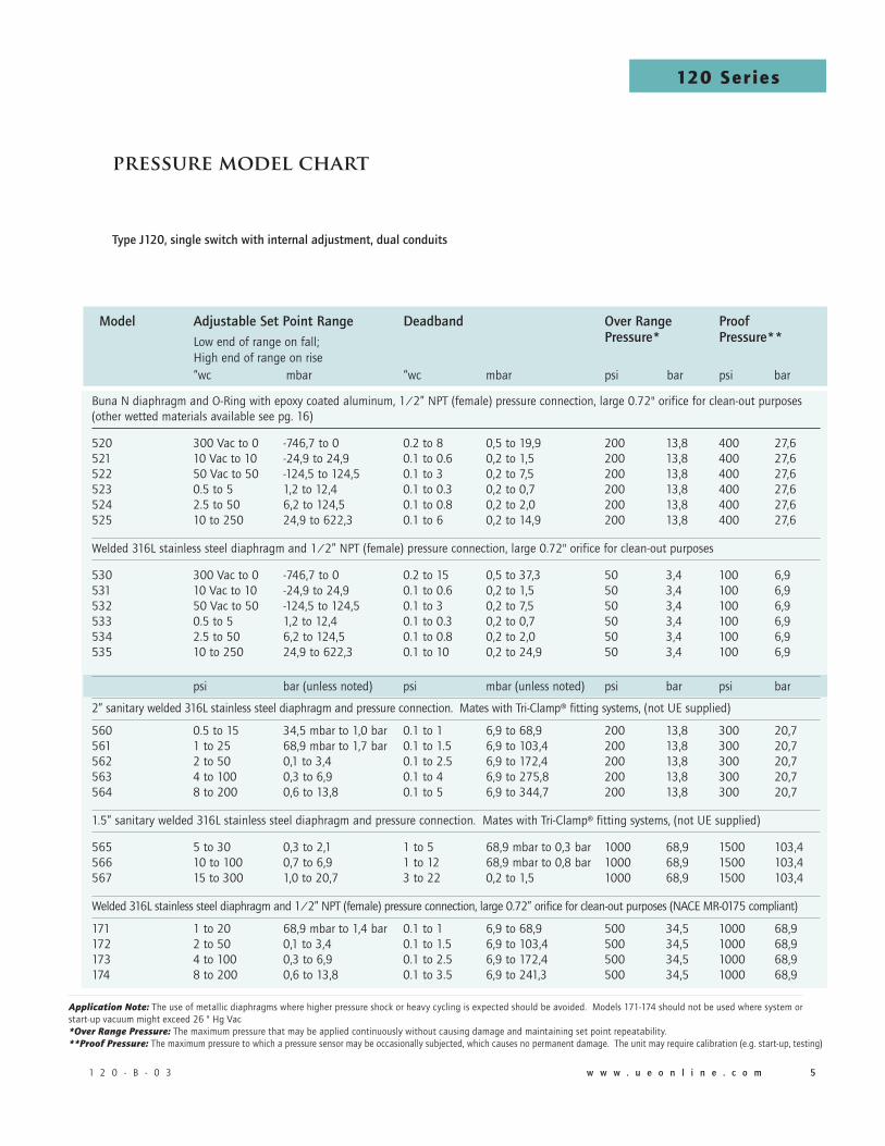
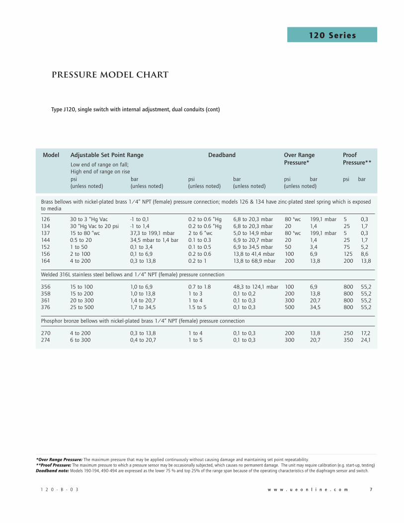
pressuremodelchart
Buna N diaphragm and O-Ring with epoxy coated aluminum, 1/2” NPT (female) pressure connection, large 0.72" orifice for clean-out purposes (other wetted materials available see pg. 16)
520 300 Vac to 0 -746,7 to 0 0.2 to 8 0,5 to 19,9 200 13,8 400 27,6521 10 Vac to 10 -24,9 to 24,9 0.1 to 0.6 0,2 to 1,5 200 13,8 400 27,6522 50 Vac to 50 -124,5 to 124,5 0.1 to 3 0,2 to 7,5 200 13,8 400 27,6523 0.5 to 5 1,2 to 12,4 0.1 to 0.3 0,2 to 0,7 200 13,8 400 27,6524 2.5 to 50 6,2 to 124,5 0.1 to 0.8 0,2 to 2,0 200 13,8 400 27,6525 10 to 250 24,9 to 622,3 0.1 to 6 0,2 to 14,9 200 13,8 400 27,6
Welded 316L stainless steel diaphragm and 1/2” NPT (female) pressure connection, large 0.72" orifice for clean-out purposes
530 300 Vac to 0 -746,7 to 0 0.2 to 15 0,5 to 37,3 50 3,4 100 6,9 531 10 Vac to 10 -24,9 to 24,9 0.1 to 0.6 0,2 to 1,5 50 3,4 100 6,9 532 50 Vac to 50 -124,5 to 124,5 0.1 to 3 0,2 to 7,5 50 3,4 100 6,9533 0.5 to 5 1,2 to 12,4 0.1 to 0.3 0,2 to 0,7 50 3,4 100 6,9534 2.5 to 50 6,2 to 124,5 0.1 to 0.8 0,2 to 2,0 50 3,4 100 6,9535 10 to 250 24,9 to 622,3 0.1 to 10 0,2 to 24,9 50 3,4 100 6,9
psi bar (unless noted) psi mbar (unless noted) psi bar psi bar
2” sanitary welded 316L stainless steel diaphragm and pressure connection. Mates with Tri-Clamp® fitting systems, (not UE supplied)
560 0.5 to 15 34,5 mbar to 1,0 bar 0.1 to 1 6,9 to 68,9 200 13,8 300 20,7561 1 to 25 68,9 mbar to 1,7 bar 0.1 to 1.5 6,9 to 103,4 200 13,8 300 20,7562 2 to 50 0,1 to 3,4 0.1 to 2.5 6,9 to 172,4 200 13,8 300 20,7563 4 to 100 0,3 to 6,9 0.1 to 4 6,9 to 275,8 200 13,8 300 20,7564 8 to 200 0,6 to 13,8 0.1 to 5 6,9 to 344,7 200 13,8 300 20,7
1.5” sanitary welded 316L stainless steel diaphragm and pressure connection. Mates with Tri-Clamp® fitting systems, (not UE supplied)
565 5 to 30 0,3 to 2,1 1 to 5 68,9 mbar to 0,3 bar 1000 68,9 1500 103,4 566 10 to 100 0,7 to 6,9 1 to 12 68,9 mbar to 0,8 bar 1000 68,9 1500 103,4 567 15 to 300 1,0 to 20,7 3 to 22 0,2 to 1,5 1000 68,9 1500 103,4
Welded 316L stainless steel diaphragm and 1/2” NPT (female) pressure connection, large 0.72” orifice for clean-out purposes (NACE MR-0175 compliant)
171 1 to 20 68,9 mbar to 1,4 bar 0.1 to 1 6,9 to 68,9 500 34,5 1000 68,9172 2 to 50 0,1 to 3,4 0.1 to 1.5 6,9 to 103,4 500 34,5 1000 68,9173 4 to 100 0,3 to 6,9 0.1 to 2.5 6,9 to 172,4 500 34,5 1000 68,9174 8 to 200 0,6 to 13,8 0.1 to 3.5 6,9 to 241,3 500 34,5 1000 68,9
TypeJ120,singleswitchwithinternaladjustment,dualconduits
Application Note: The use of metallic diaphragms where higher pressure shock or heavy cycling is expected should be avoided. Models 171-174 should not be used where system or start-up vacuum might exceed 26 " Hg Vac *Over Range Pressure: The maximum pressure that may be applied continuously without causing damage and maintaining set point repeatability. **Proof Pressure: The maximum pressure to which a pressure sensor may be occasionally subjected, which causes no permanent damage. The unit may require calibration (e.g. start-up, testing)
Model AdjustableSetPointRange Deadband OverRange Proof Low end of range on fall; Pressure* Pressure** High end of range on rise
“wc mbar “wc mbar psi bar psi bar
1 2 0 - B - 0 3 w w w . u e o n l i n e . c o m �� w w w . u e o n l i n e . c o m 1 2 0 - B - 0 3
120 Series1
20
Se
rie
s
1 2 0 - B - 0 3 w w w . u e o n l i n e . c o m �� w w w . u e o n l i n e . c o m 1 2 0 - B - 0 3
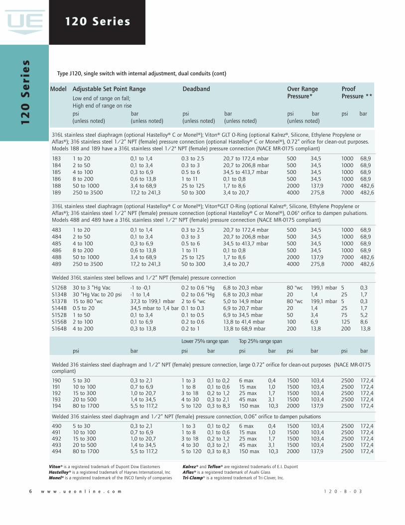
TypeJ120,singleswitchwithinternaladjustment,dualconduits(cont)
Viton® is a registered trademark of Dupont Dow ElastomersHastelloy® is a registered trademark of Haynes International, IncMonel® is a registered trademark of the INCO family of companies
Kalrez® and Teflon® are registered trademarks of E.I. DupontAflas® is a registered trademark of Asahi GlassTri-Clamp® is a registered trademark of Tri-Clover, Inc.
Model AdjustableSetPointRange Deadband OverRange Proof Low end of range on fall; Pressure* Pressure** High end of range on rise
psi bar psi bar psi bar psi bar (unless noted) (unless noted) (unless noted) (unless noted) (unless noted)
316L stainless steel diaphragm (optional Hastelloy® C or Monel®); Viton® GLT O-Ring (optional Kalrez®, Silicone, Ethylene Propylene or Aflas®); 316 stainless steel 1/2” NPT (female) pressure connection (optional Hastelloy® C or Monel®), 0.72” orifice for clean-out purposes. Models 188 and 189 have a 316L stainless steel 1/2" NPT (female) pressure connection (NACE MR-0175 compliant)
183 1 to 20 0,1 to 1,4 0.3 to 2.5 20,7 to 172,4 mbar 500 34,5 1000 68,9184 2 to 50 0,1 to 3,4 0.3 to 3 20,7 to 206,8 mbar 500 34,5 1000 68,9185 4 to 100 0,3 to 6,9 0.5 to 6 34,5 to 413,7 mbar 500 34,5 1000 68,9186 8 to 200 0,6 to 13,8 1 to 11 0,1 to 0,8 500 34,5 1000 68,9188 50 to 1000 3,4 to 68,9 25 to 125 1,7 to 8,6 2000 137,9 7000 482,6189 250 to 3500 17,2 to 241,3 50 to 300 3,4 to 20,7 4000 275,8 7000 482,6
316L stainless steel diaphragm (optional Hastelloy® C or Monel®); Viton®GLT O-Ring (optional Kalrez®, Silicone, Ethylene Propylene or Aflas®); 316 stainless steel 1/2” NPT (female) pressure connection (optional Hastelloy® C or Monel®), 0.06" orifice to dampen pulsations. Models 488 and 489 have a 316L stainless steel 1/2" NPT (female) pressure connection (NACE MR-0175 compliant)
483 1 to 20 0,1 to 1,4 0.3 to 2.5 20,7 to 172,4 mbar 500 34,5 1000 68,9 484 2 to 50 0,1 to 3,4 0.3 to 3 20,7 to 206,8 mbar 500 34,5 1000 68,9 485 4 to 100 0,3 to 6,9 0.5 to 6 34,5 to 413,7 mbar 500 34,5 1000 68,9 486 8 to 200 0,6 to 13,8 1 to 11 0,1 to 0,8 500 34,5 1000 68,9 488 50 to 1000 3,4 to 68,9 25 to 125 1,7 to 8,6 2000 137,9 7000 482,6 489 250 to 3500 17,2 to 241,3 50 to 300 3,4 to 20,7 4000 275,8 7000 482,6
Welded 316L stainless steel bellows and 1/2” NPT (female) pressure connection
S126B 30 to 3 ”Hg Vac -1 to -0,1 0.2 to 0.6 "Hg 6,8 to 20,3 mbar 80 "wc 199,1 mbar 5 0,3S134B 30 ”Hg Vac to 20 psi -1 to 1,4 0.2 to 0.6 "Hg 6,8 to 20,3 mbar 20 1,4 25 1,7S137B 15 to 80 ”wc 37,3 to 199,1 mbar 2 to 6 "wc 5,0 to 14,9 mbar 80 "wc 199,1 mbar 5 0,3S144B 0.5 to 20 34,5 mbar to 1,4 bar 0.1 to 0.3 6,9 to 20,7 mbar 20 1,4 25 1,7S152B 1 to 50 0,1 to 3,4 0.1 to 0.5 6,9 to 34,5 mbar 50 3,4 75 5,2S156B 2 to 100 0,1 to 6,9 0.2 to 0.6 13,8 to 41,4 mbar 100 6,9 125 8,6S164B 4 to 200 0,3 to 13,8 0.2 to 1 13,8 to 68,9 mbar 200 13,8 200 13,8
Lower 75% range span Top 25% range span
psi bar psi bar psi bar psi bar psi bar
Welded 316 stainless steel diaphragm and 1/2” NPT (female) pressure connection, large 0.72” orifice for clean-out purposes (NACE MR-0175 compliant)
190 5 to 30 0,3 to 2,1 1 to 3 0,1 to 0,2 6 max 0,4 1500 103,4 2500 172,4191 10 to 100 0,7 to 6,9 1 to 8 0,1 to 0,6 15 max 1,0 1500 103,4 2500 172,4192 15 to 300 1,0 to 20,7 3 to 18 0,2 to 1,2 25 max 1,7 1500 103,4 2500 172,4193 20 to 500 1,4 to 34,5 4 to 30 0,3 to 2,1 45 max 3,1 1500 103,4 2500 172,4194 80 to 1700 5,5 to 117,2 5 to 120 0,3 to 8,3 150 max 10,3 2000 137,9 2500 172,4
Welded 316 stainless steel diaphragm and 1/2” NPT (female) pressure connection, 0.06” orifice to dampen pulsations
490 5 to 30 0,3 to 2,1 1 to 3 0,1 to 0,2 6 max 0,4 1500 103,4 2500 172,4491 10 to 100 0,7 to 6,9 1 to 8 0,1 to 0,6 15 max 1,0 1500 103,4 2500 172,4492 15 to 300 1,0 to 20,7 3 to 18 0,2 to 1,2 25 max 1,7 1500 103,4 2500 172,4493 20 to 500 1,4 to 34,5 4 to 30 0,3 to 2,1 45 max 3,1 1500 103,4 2500 172,4494 80 to 1700 5,5 to 117,2 5 to 120 0,3 to 8,3 150 max 10,3 2000 137,9 2500 172,4
1 2 0 - B - 0 3 w w w . u e o n l i n e . c o m �� w w w . u e o n l i n e . c o m 1 2 0 - B - 0 3 1 2 0 - B - 0 3 w w w . u e o n l i n e . c o m �� w w w . u e o n l i n e . c o m 1 2 0 - B - 0 3
120 Series
pressuremodelchart
Model AdjustableSetPointRange Deadband OverRange Proof Low end of range on fall; Pressure* Pressure** High end of range on rise
psi bar psi bar psi bar psi bar (unless noted) (unless noted) (unless noted) (unless noted) (unless noted)
Brass bellows with nickel-plated brass 1/4” NPT (female) pressure connection; models 126 & 134 have zinc-plated steel spring which is exposed to media
126 30 to 3 ”Hg Vac -1 to 0,1 0.2 to 0.6 ”Hg 6,8 to 20,3 mbar 80 "wc 199,1 mbar 5 0,3134 30 ”Hg Vac to 20 psi -1 to 1,4 0.2 to 0.6 ”Hg 6,8 to 20,3 mbar 20 1,4 25 1,7137 15 to 80 ”wc 37,3 to 199,1 mbar 2 to 6 ”wc 5,0 to 14,9 mbar 80 "wc 199,1 mbar 5 0,3144 0.5 to 20 34,5 mbar to 1,4 bar 0.1 to 0.3 6,9 to 20,7 mbar 20 1,4 25 1,7152 1 to 50 0,1 to 3,4 0.1 to 0.5 6,9 to 34,5 mbar 50 3,4 75 5,2156 2 to 100 0,1 to 6,9 0.2 to 0.6 13,8 to 41,4 mbar 100 6,9 125 8,6164 4 to 200 0,3 to 13,8 0.2 to 1 13,8 to 68,9 mbar 200 13,8 200 13,8
Welded 316L stainless steel bellows and 1/4” NPT (female) pressure connection
356 15 to 100 1,0 to 6,9 0.7 to 1.8 48,3 to 124,1 mbar 100 6,9 800 55,2358 15 to 200 1,0 to 13,8 1 to 3 0,1 to 0,2 200 13,8 800 55,2361 20 to 300 1,4 to 20,7 1 to 4 0,1 to 0,3 300 20,7 800 55,2376 25 to 500 1,7 to 34,5 1.5 to 5 0,1 to 0,3 500 34,5 800 55,2
Phosphor bronze bellows with nickel-plated brass 1/4” NPT (female) pressure connection
270 4 to 200 0,3 to 13,8 1 to 4 0,1 to 0,3 200 13,8 250 17,2274 6 to 300 0,4 to 20,7 1 to 5 0,1 to 0,3 300 20,7 350 24,1
TypeJ120,singleswitchwithinternaladjustment,dualconduits(cont)
*Over Range Pressure: The maximum pressure that may be applied continuously without causing damage and maintaining set point repeatability. **Proof Pressure: The maximum pressure to which a pressure sensor may be occasionally subjected, which causes no permanent damage. The unit may require calibration (e.g. start-up, testing)Deadband note: Models 190-194, 490-494 are expressed as the lower 75 % and top 25% of the range span because of the operating characteristics of the diaphragm sensor and switch.

1 2 0 - B - 0 3 w w w . u e o n l i n e . c o m �� w w w . u e o n l i n e . c o m 1 2 0 - B - 0 3
120 Series1
20
Se
rie
s
1 2 0 - B - 0 3 w w w . u e o n l i n e . c o m �� w w w . u e o n l i n e . c o m 1 2 0 - B - 0 3
Model AdjustableSetPointRange Deadband OverRange Proof Low end of range on fall; Pressure* Pressure** High end of range on rise
psi bar psi bar psi bar psi bar (unless noted) (unless noted) (unless noted) (unless noted) (unless noted)
303 stainless steel piston with Buna N O-Ring and 303 stainless steel 1/4” NPT (female) pressure connection (not recommended for gas service since drying of the O-Ring seal can allow bleeding of medium into the atmosphere)
612 125 to 3000 8,6 to 206,8 40 to 250 2,8 to 17,2 6000 413,7 10000 689,5616 700 to 5000 48,3 to 344,7 40 to 375 2,8 to 25,9 6000 413,7 10000 689,5
316 stainless steel bellows and 1/4” NPT (female) pressure connection (not recommended for rapid or high cycling pressure changes)
680 100 to 1700 6,9 to 117,2 9 to 40 0,6 to 2,8 1700 117,2 2500 172,4
Buna N diaphragm and O-Ring with nickel-plated brass 1/4” NPT (female) pressure connection; Optional Viton diaphragm and O-Ring available
701 1.5 to 30 103,4 mbar to 2,1 bar 1 to 2 68,9 mbar to 0,1 bar 500 34,5 1000 68.9
702 3 to 100 0,2 to 6,9 1 to 4 68,9 to 0,3 bar 500 34,5 1000 68,9
703 9 to 300 0,6 to 20,7 1 to 5 68,9 to 0,3 bar 500 34,5 1000 68,9704 15 to 500 1,0 to 34,5 2 to 8 0,1 to 0,6 1500 103,4 2500 172,4705 30 to 1000 2,1 to 68,9 3 to 20 0,2 to 1,4 1500 103,4 2500 172,4
Viton® diaphragm and O-ring with 1/4" NPT (female) 303 stainless steel pressure connection (includes adjustable deadband switch)
15622 20 to 200 1,4 to 13,8 12 to 26 0,8 to 1,8 500 34,5 1000 68,9
Buna N diaphragm and O-Ring with 1/4” NPT (female) aluminum connection and cap
450 30 ”Hg Vac to 3 ”Hg Vac -1 to -0,1 0.1 to 0.3 ”Hg 3,4 to 10,2 mbar 80 "wc 199,1 mbar 225 15,5451 2 to 80” wc 5 to 199,1 mbar 0.8 to 2 ”wc 2 to 5 mbar 80 ”wc 199,1 mbar 225 15,5452 30 ”Hg Vac to 20 psi -1,0 to 1,4 0.1 to 0.4 ”Hg 3,4 to 13,5 mbar 20 1,4 225 15,5 453 0.5 to 20 34,5 mbar to 1,4 bar 0.05 to 0.1 3,4 to 6,9 mbar 20 1,4 225 15,5454 0.8 to 30 55,2 mbar to 2,1 bar 0.05 to 0.2 3,4 to 13,8 mbar 30 2,1 225 15,5
Teflon® diaphragm and O-Ring 316 stainless steel with 1/4” NPT (female) 316 stainless steel pressure connection and cap
550 30 "Hg Vac to 3 "Hg Vac -1 to -0,1 0.1 to 0.4 "Hg 3,4 to 13,5 mbar 80 "wc 199,1 mbar 225 15,5551 2 to 80 ”wc 5 to 199,1 mbar 1 to 4 "wc 2,5 to 10 mbar 80 "wc 199,1 mbar 225 15,5552 30 "Hg Vac to 20 psi -1,0 to 1,4 0.2 to 0.5 "Hg 6,8 to 16,9 mbar 20 1,4 225 15,5553 0.5 to 20 34,5 mbar to 1,4 bar 0.1 to 0.2 6,9 to 13,8 mbar 20 1,4 225 15,5554 0.8 to 30 55,2 mbar to 2,1 bar 0.1 to 0.3 6,9 to 20,7 mbar 30 2,1 225 15,5555 2 to 100 0,1 to 6,9 0.2 to 0.4 13,8 to 27,6 mbar 100 6,9 225 15,5
Teflon® is a registered trademark of E.I. DuPont *Over Range Pressure: The maximum pressure that may be applied continuously without causing damage and maintaining set point repeatability. **Proof Pressure: The maximum pressure to which a pressure sensor may be occasionally subjected, which causes no permanent damage. The unit may require calibration (e.g. start-up, testing)
TypeJ120,singleswitchwithinternaladjustment,dualconduits(cont)

1 2 0 - B - 0 3 w w w . u e o n l i n e . c o m �� w w w . u e o n l i n e . c o m 1 2 0 - B - 0 3 1 2 0 - B - 0 3 w w w . u e o n l i n e . c o m �� w w w . u e o n l i n e . c o m 1 2 0 - B - 0 3
120 Series
Welded 316L stainless steel bellows and 1/2” NPT (female) pressure connection
S126B 30 ”Hg Vac to 0 psi -1 to 0 0.2 to 0.9 ”Hg 6,8 to 30,5 mbar 5 0, 3 0.5 "HgS134B 30 ”Hg Vac to 20 psi -1 to 1,4 0.2 to 1.2 ”Hg 6,8 to 40,6 mbar 25 1, 7 1 "Hg & 0.5 psiS137B† 2 to 80 ”wc 5 to 199,1 mbar 2 to 10 ”wc 5 to 24,9 mbar 5 0,3 2 "wcS144B 0 to 20 0 to 1,4 0.1 to 0.5 6,9 to 34,5 mbar 25 1,7 0.5 S146B 0 to 30 0 to 2,1 0.1 to 0.6 6,9 to 41,4 mbar 40 2,8 0.5 S156B 0 to 100 0 to 6,9 0.2 to 0.8 13,8 to 55,2 mbar 125 8,6 2 S164B 0 to 200 0 to 13,8 0.3 to 2 20,7 to 137,9 mbar 200 13,8 5
Brass bellows with nickel-plated brass 1/4” NPT (female) pressure connection; models 126 & 134 have a zinc-plated steel spring which is exposed to media
126 30 ”Hg Vac to 0 psi -1 to 0 0.2 to 0.9 ”Hg 6,8 to 30,5 mbar 5 0,3 0.5 "Hg134 30 ”Hg Vac to 20 psi -1 to 1,4 0.2 to 1.2 ”Hg 6,8 to 40,6 mbar 25 1,7 1 ”Hg & 0.5 psi137† 2 to 80 ”wc 5 to 199,1 mbar 2 to 10 ”wc 5 to 24,9 mbar 5 0,3 2 ”wc144 0 to 20 0 to 1,4 0.1 to 0.5 6,9 to 34,5 mbar 25 1,7 0.5 146 0 to 30 0 to 2,1 0.1 to 0.6 6,9 to 41,4 mbar 40 2,8 0.5 156 0 to 100 0 to 6,9 0.2 to 0.8 13,8 to 55,2 mbar 125 8,6 2 164 0 to 200 0 to 13,8 0.3 to 2 20,7 to 137,9 mbar 200 13,8 5
316L stainless steel bellows and 1/4” NPT (female) pressure connection
358 0 to 200 0 to 13,8 1.5 to 8 0,1 to 0,6 250 17,2 5 361 0 to 300 0 to 20,7 2 to 9 0,1 to 0,6 350 24,1 10 376 0 to 500 0 to 34,5 3 to 12 0,2 to 0,8 575 39,6 10
303 stainless steel piston with Buna N O-Ring and 303 stainless steel 1/4” NPT (female) pressure connection (not recommended for gas service since drying of the O-Ring seal can allow bleeding of medium into the atmosphere)
612 200 to 3000 13,8 to 206,8 40 to 250 2,8 to 17,2 10,000 689,5 50 614 500 to 6000 34,5 to 413,7 50 to 400 3,4 to 27,6 10,000 689,5 100
pressuremodelchart
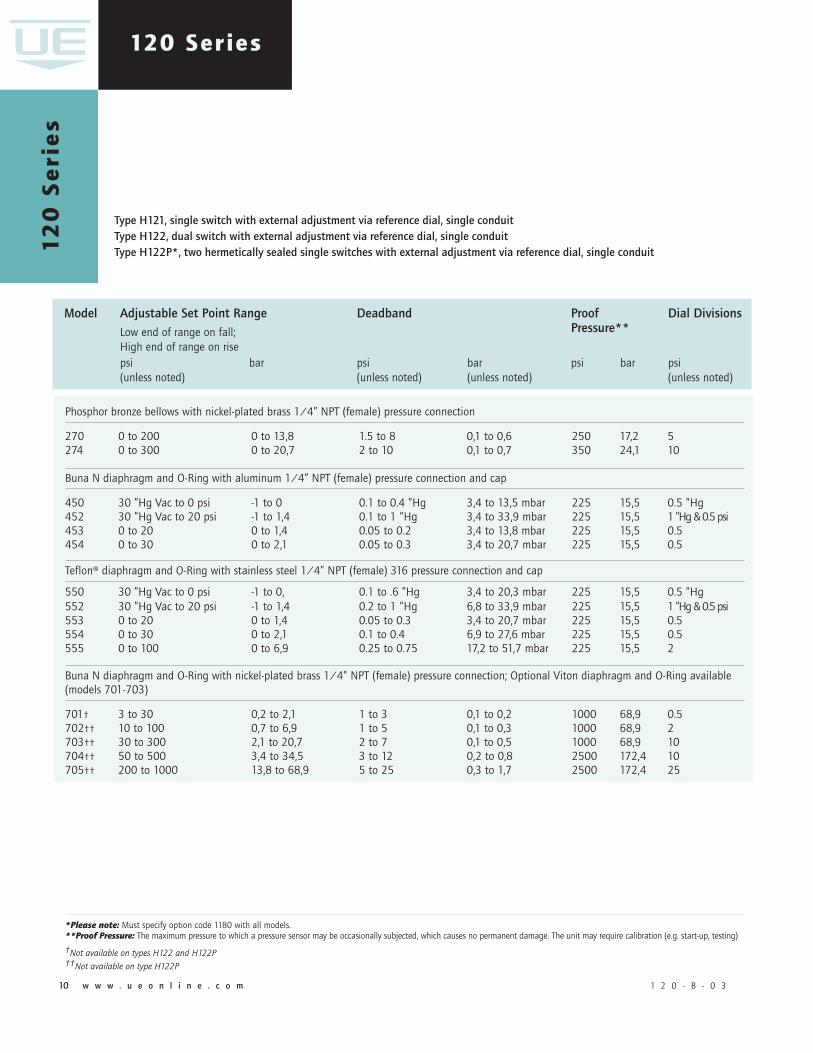
TypeH121,singleswitchwithexternaladjustmentviareferencedial,singleconduitTypeH122,dualswitchwithexternaladjustmentviareferencedial,singleconduitTypeH122P*,twohermeticallysealedsingleswitcheswithexternaladjustmentviareferencedial,singleconduit
Model AdjustableSetPointRange Deadband Proof DialDivisions Low end of range on fall; Pressure** High end of range on rise
psi bar psi bar psi bar psi (unless noted) (unless noted) (unless noted) (unless noted) (unless noted)
*Please note: Must specify option code 1180 with all models. **Proof Pressure: The maximum pressure to which a pressure sensor may be occasionally subjected, which causes no permanent damage. The unit may require calibration (e.g. start-up, testing)
†Not available on types H122 and H122P
1 2 0 - B - 0 3 w w w . u e o n l i n e . c o m 1110 w w w . u e o n l i n e . c o m 1 2 0 - B - 0 3
120 Series1
20
Se
rie
s
1 2 0 - B - 0 3 w w w . u e o n l i n e . c o m 1110 w w w . u e o n l i n e . c o m 1 2 0 - B - 0 3
Phosphor bronze bellows with nickel-plated brass 1/4” NPT (female) pressure connection
270 0 to 200 0 to 13,8 1.5 to 8 0,1 to 0,6 250 17,2 5 274 0 to 300 0 to 20,7 2 to 10 0,1 to 0,7 350 24,1 10
Buna N diaphragm and O-Ring with aluminum 1/4” NPT (female) pressure connection and cap
450 30 ”Hg Vac to 0 psi -1 to 0 0.1 to 0.4 ”Hg 3,4 to 13,5 mbar 225 15,5 0.5 ”Hg452 30 ”Hg Vac to 20 psi -1 to 1,4 0.1 to 1 ”Hg 3,4 to 33,9 mbar 225 15,5 1 ”Hg & 0.5 psi453 0 to 20 0 to 1,4 0.05 to 0.2 3,4 to 13,8 mbar 225 15,5 0.5 454 0 to 30 0 to 2,1 0.05 to 0.3 3,4 to 20,7 mbar 225 15,5 0.5
Teflon® diaphragm and O-Ring with stainless steel 1/4” NPT (female) 316 pressure connection and cap
550 30 ”Hg Vac to 0 psi -1 to 0, 0.1 to .6 ”Hg 3,4 to 20,3 mbar 225 15,5 0.5 ”Hg552 30 ”Hg Vac to 20 psi -1 to 1,4 0.2 to 1 ”Hg 6,8 to 33,9 mbar 225 15,5 1 ”Hg & 0.5 psi 553 0 to 20 0 to 1,4 0.05 to 0.3 3,4 to 20,7 mbar 225 15,5 0.5554 0 to 30 0 to 2,1 0.1 to 0.4 6,9 to 27,6 mbar 225 15,5 0.5 555 0 to 100 0 to 6,9 0.25 to 0.75 17,2 to 51,7 mbar 225 15,5 2
Buna N diaphragm and O-Ring with nickel-plated brass 1/4” NPT (female) pressure connection; Optional Viton diaphragm and O-Ring available (models 701-703)
701† 3 to 30 0,2 to 2,1 1 to 3 0,1 to 0,2 1000 68,9 0.5 702†† 10 to 100 0,7 to 6,9 1 to 5 0,1 to 0,3 1000 68,9 2703†† 30 to 300 2,1 to 20,7 2 to 7 0,1 to 0,5 1000 68,9 10 704†† 50 to 500 3,4 to 34,5 3 to 12 0,2 to 0,8 2500 172,4 10 705†† 200 to 1000 13,8 to 68,9 5 to 25 0,3 to 1,7 2500 172,4 25
*Please note: Must specify option code 1180 with all models. **Proof Pressure: The maximum pressure to which a pressure sensor may be occasionally subjected, which causes no permanent damage. The unit may require calibration (e.g. start-up, testing)
†Not available on types H122 and H122P ††Not available on type H122P
TypeH121,singleswitchwithexternaladjustmentviareferencedial,singleconduitTypeH122,dualswitchwithexternaladjustmentviareferencedial,singleconduitTypeH122P*,twohermeticallysealedsingleswitcheswithexternaladjustmentviareferencedial,singleconduit
Model AdjustableSetPointRange Deadband Proof DialDivisions Low end of range on fall; Pressure** High end of range on rise
psi bar psi bar psi bar psi (unless noted) (unless noted) (unless noted) (unless noted)
1 2 0 - B - 0 3 w w w . u e o n l i n e . c o m 1110 w w w . u e o n l i n e . c o m 1 2 0 - B - 0 3 1 2 0 - B - 0 3 w w w . u e o n l i n e . c o m 1110 w w w . u e o n l i n e . c o m 1 2 0 - B - 0 3
120 Series
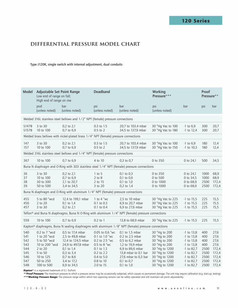
differentialpressuremodelchart
Model AdjustableSetPointRange Deadband Working Proof Low end of range on fall; Pressure*** Pressure** High end of range on rise
psid bar psi bar psi bar psi bar (unless noted) (unless noted) (unless noted) (unless noted) (unless noted)
Welded 316L stainless steel bellows and 1/2” NPT (female) pressure connections
S147B 3 to 30 0,2 to 2,1 0.3 to 1.5 20,7 to 103,4 mbar 30 ”Hg Vac to 100 -1 to 6,9 300 20,7S157B 10 to 100 0,7 to 6,9 0.5 to 2 34,5 to 137,9 mbar 30 ”Hg Vac to 180 -1 to 12,4 300 20,7
Welded brass bellows with nickel-plated brass 1/4” NPT (female) pressure connections
147 3 to 30 0,2 to 2,1 0.3 to 1.5 20,7 to 103,4 mbar 30 ”Hg Vac to 100 -1 to 6,9 180 12,4157 10 to 100 0,7 to 6,9 0.5 to 2 34,5 to 137,9 mbar 30 ”Hg Vac to 150 -1 to 10,3 180 12,4
Welded 316L stainless steel bellows and 1/4” NPT (female) pressure connections
367 10 to 100 0,7 to 6,9 4 to 10 0,3 to 0,7 0 to 350 0 to 24,1 500 34,5
Buna N diaphragm and O-Ring with 303 stainless steel 1/4” NPT (female) pressure connections
36 3 to 30 0,2 to 2,1 1 to 5 0,1 to 0,3 0 to 350 0 to 24,1 1000 68,937 10 to 100 0,7 to 6,9 2 to 8 0,1 to 0,6 0 to 500 0 to 34,5 1000 68,938 30 to 300 2,1 to 20,7 2 to 15 0,1 to 1,0 0 to 1000 0 to 68,9 2500 172,439 50 to 500 3,4 to 34,5 3 to 20 0,2 to 1,4 0 to 1000 0 to 68,9 2500 172,4
Buna N diaphragm and O-Ring with aluminum 1/4” NPT (female) pressure connections
455 5 to 80 ”wcd 12,4 to 199,1 mbar 1 to 4 ”wc 2,5 to 10 mbar 30 ”Hg Vac to 225 -1 to 15,5 225 15,5456 2 to 20 0,1 to 1,4 0.1 to 0.3 6,9 to 20,7 mbar 30 ”Hg Vac to 225 -1 to 15,5 225 15,5457 3 to 30 0,2 to 2,1 0.1 to 0.4 6,9 to 27,6 mbar 30 ”Hg Vac to 225 -1 to 15,5 225 15,5
Teflon® and Buna N diaphragms, Buna N O-Ring with aluminum 1/4” NPT (female) pressure connections
559 10 to 100 0,7 to 6,9 0.2 to 1 13,8 to 68,9 mbar 30 ”Hg Vac to 225 -1 to 15,5 225 15,5
Kapton® diaphragms, Buna N sealing diaphragms with aluminum 1/8” NPT (female) pressure connections
540 0.2 to 7 “wcd 0,5 to 17,4 mbar 0.05 to 0,6 “wc 0,1 to 1,5 mbar 30 ”Hg to 200 -1 to 13,8 400 27,6541 1 to 20 “wcd 2,5 to 49,8 mbar 0.1 to 1.0 “wc 0.2 to 2,5 mbar 30 ”Hg to 200 -1 to 13,8 400 27,6542 5 to 50 “wcd 12,4 to 124,5 mbar 0.2 to 2.5 “wc 0,5 to 6,2 mbar 30 ”Hg to 200 -1 to 13,8 400 27,6543 10 to 200 “wcd 24,9 to 497,8 mbar 0.5 to 8 “wc 1,2 to 19,9 mbar 30 ”Hg to 200 -1 to 13,8 400 27,6544 2 to 20 0,1 to 1,4 0.1 to 1.3 6,9 to 89,6 mbar 30 ”Hg to 1200 -1 to 82,7 2500 172,4545 5 to 50 0,3 to 3,4 0.2 to 2.2 13,8 mbar to 0,1 bar 30 ”Hg to 1200 -1 to 82,7 2500 172,4546 10 to 125 0,7 to 8,6 0.4 to 5.0 27,6 mbar to 0,3 bar 30 ”Hg to 1200 -1 to 82,7 2500 172,4547 50 to 250 3,4 to 17,2 0.8 to 10 0,1 to 0,7 30 ”Hg to 1200 -1 to 82,7 2500 172,4548 100 to 500 6,9 to 34,5 2.0 to 15 0,1 to 1,0 30 ”Hg to 1200 -1 to 82,7 2500 172,4
Kapton® is a registered trademark of E.I. DuPont **Proof Pressure: The maximum pressure to which a pressure sensor may be occasionally subjected, which causes no permanent damage. The unit may require calibration (e.g. start-up, testing) ***Working Pressure Range: The pressure range within which two opposing sensors can be safely operated and still maintain set point adjustability.
TypeJ120K,singleswitchwithinternaladjustment,dualconduits

1 2 0 - B - 0 3 w w w . u e o n l i n e . c o m 1�12 w w w . u e o n l i n e . c o m 1 2 0 - B - 0 3
120 Series1
20
Se
rie
s
1 2 0 - B - 0 3 w w w . u e o n l i n e . c o m 1�12 w w w . u e o n l i n e . c o m 1 2 0 - B - 0 3
Model AdjustableSetPointRange Deadband Working Proof Dial Low end of range on fall; Pressure*** Pressure** Divisions High end of range on rise
psid bar psi mbar psi bar psi bar psi (unless noted)
Welded 316L stainless steel bellows and 1/2” NPT (female) pressure connections
S147B 3 to 30 0,2 to 2,1 0.3 to 2 20,7 to 137,9 30 ”Hg Vac to 100 -1 to 6,9 300 20,7 0.5S157B 10 to 100 0,7 to 6,9 0.5 to 3 34,5 to 206,8 30 ”Hg Vac to 180 -1 to 12,4 300 20,7 2
Welded brass bellows with nickel-plated brass 1/4” NPT (female) pressure connections
147 3 to 30 0,2 to 2,1 0.3 to 2 20,7 to 137,9 30 ”Hg Vac to 100 -1 to 6,9 180 12,4 0.5157 10 to 100 0,7 to 6,9 0.5 to 3 34,5 to 206,8 30 ”Hg Vac to 150 -1 to 10,3 180 12,4 2
Buna N diaphragm, O-Ring with aluminum 1/4” NPT (female) pressure connections
456 2 to 20 0,1 to 1,4 0.1 to 0.3 6,9 to 20,7 30 ”Hg Vac to 225 -1 to 15,5 225 15,5 0.5457 3 to 30 0,2 to 2,1 0.1 to 0.4 6,9 to 27,6 30 ”Hg Vac to 225 -1 to 15,5 225 15,5 0.5
Teflon® and Buna N diaphragms, Buna N O-Ring with aluminum 1/4” NPT (female) pressure connections
559 10 to 100 0,7 to 6,9 0.2 to 1 13,8 to 68,9 30 ”Hg Vac to 225 -1 to 15,5 225 15,5 2
**Proof Pressure: The maximum pressure to which a pressure sensor may be occasionally subjected, which causes no permanent damage. The unit may require calibration (e.g. start-up, testing) ***Working Pressure Range: The pressure range within which two opposing sensors can be safely operated and still maintain set point adjustability.
TypeH121K,singleswitchwithexternaladjustmentdialviareferencedial,singleconduitTypeH122K,dualswitchwithexternaladjustmentdialviareferencedial,singleconduit
Differential Pressure Indicating Option M210
1 2 0 - B - 0 3 w w w . u e o n l i n e . c o m 1�12 w w w . u e o n l i n e . c o m 1 2 0 - B - 0 3 1 2 0 - B - 0 3 w w w . u e o n l i n e . c o m 1�12 w w w . u e o n l i n e . c o m 1 2 0 - B - 0 3
120 Series
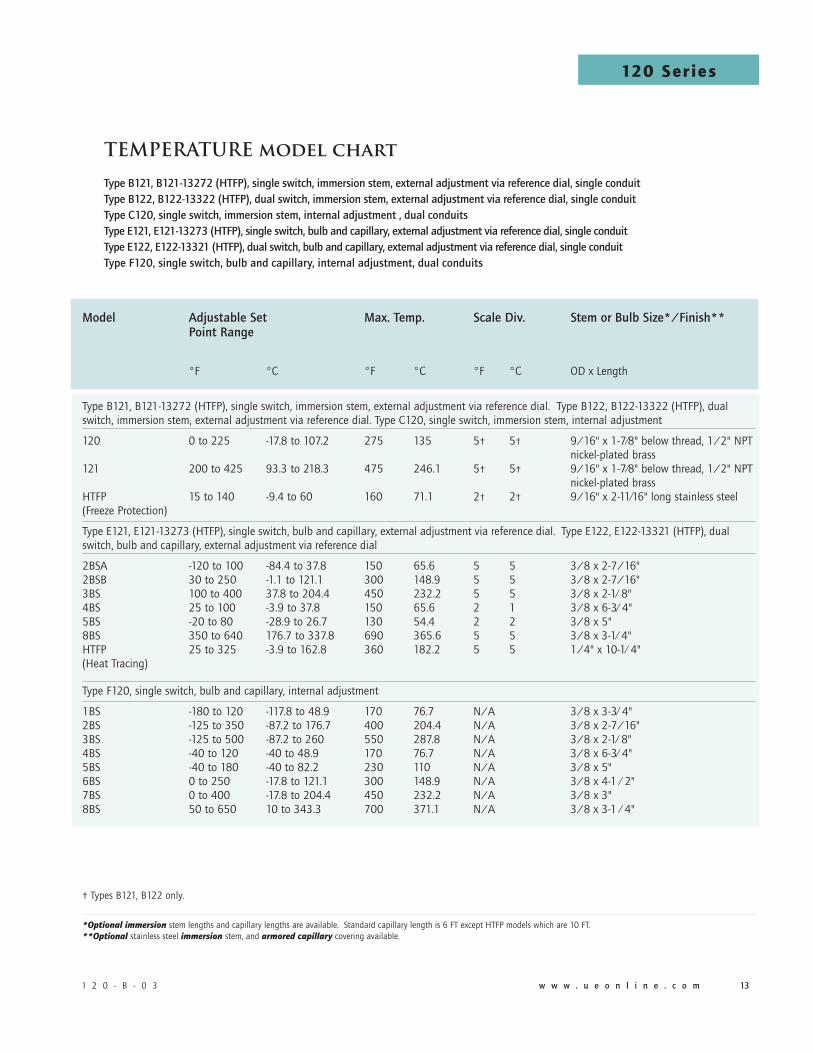
Model AdjustableSet Max.Temp. ScaleDiv. StemorBulbSize*/Finish** PointRange
°F °C °F °C °F °C OD x Length
Type B121, B121-13272 (HTFP), single switch, immersion stem, external adjustment via reference dial. Type B122, B122-13322 (HTFP), dual switch, immersion stem, external adjustment via reference dial. Type C120, single switch, immersion stem, internal adjustment
120 0 to 225 -17.8 to 107.2 275 135 5† 5† 9/16" x 1-7⁄8" below thread, 1/2" NPT nickel-plated brass 121 200 to 425 93.3 to 218.3 475 246.1 5† 5† 9/16" x 1-7⁄8" below thread, 1/2" NPT nickel-plated brass HTFP 15 to 140 -9.4 to 60 160 71.1 2† 2† 9/16" x 2-11⁄16" long stainless steel (Freeze Protection)
Type E121, E121-13273 (HTFP), single switch, bulb and capillary, external adjustment via reference dial. Type E122, E122-13321 (HTFP), dual switch, bulb and capillary, external adjustment via reference dial
2BSA -120 to 100 -84.4 to 37.8 150 65.6 5 5 3/8 x 2-7/16" 2BSB 30 to 250 -1.1 to 121.1 300 148.9 5 5 3/8 x 2-7/16" 3BS 100 to 400 37.8 to 204.4 450 232.2 5 5 3/8 x 2-1⁄ 8" 4BS 25 to 100 -3.9 to 37.8 150 65.6 2 1 3/8 x 6-3⁄ 4" 5BS -20 to 80 -28.9 to 26.7 130 54.4 2 2 3/8 x 5" 8BS 350 to 640 176.7 to 337.8 690 365.6 5 5 3/8 x 3-1⁄ 4" HTFP 25 to 325 -3.9 to 162.8 360 182.2 5 5 1/4" x 10-1⁄ 4" (Heat Tracing)
Type F120, single switch, bulb and capillary, internal adjustment
1BS -180 to 120 -117.8 to 48.9 170 76.7 N/A 3/8 x 3-3⁄ 4" 2BS -125 to 350 -87.2 to 176.7 400 204.4 N/A 3/8 x 2-7/16" 3BS -125 to 500 -87.2 to 260 550 287.8 N/A 3/8 x 2-1⁄ 8" 4BS -40 to 120 -40 to 48.9 170 76.7 N/A 3/8 x 6-3⁄ 4" 5BS -40 to 180 -40 to 82.2 230 110 N/A 3/8 x 5" 6BS 0 to 250 -17.8 to 121.1 300 148.9 N/A 3/8 x 4-1 ⁄ 2" 7BS 0 to 400 -17.8 to 204.4 450 232.2 N/A 3/8 x 3" 8BS 50 to 650 10 to 343.3 700 371.1 N/A 3/8 x 3-1 ⁄ 4"
† Types B121, B122 only.
*Optional immersion stem lengths and capillary lengths are available. Standard capillary length is 6 FT except HTFP models which are 10 FT. **Optional stainless steel immersion stem, and armored capillary covering available.
TeMperaTUremodelchart
TypeB121,B121-13272(HTFP),singleswitch,immersionstem,externaladjustmentviareferencedial,singleconduitTypeB122,B122-13322(HTFP),dualswitch,immersionstem,externaladjustmentviareferencedial,singleconduitTypeC120,singleswitch,immersionstem,internaladjustment,dualconduitsTypeE121,E121-13273(HTFP),singleswitch,bulbandcapillary,externaladjustmentviareferencedial,singleconduitTypeE122,E122-13321(HTFP),dualswitch,bulbandcapillary,externaladjustmentviareferencedial,singleconduitTypeF120,singleswitch,bulbandcapillary,internaladjustment,dualconduits
1 2 0 - B - 0 3 w w w . u e o n l i n e . c o m 1�1� w w w . u e o n l i n e . c o m 1 2 0 - B - 0 3
120 Series1
20
Se
rie
s
1 2 0 - B - 0 3 w w w . u e o n l i n e . c o m 1�1� w w w . u e o n l i n e . c o m 1 2 0 - B - 0 3
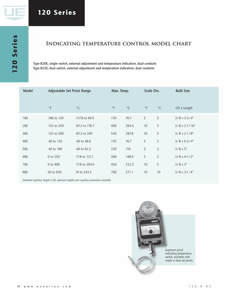
Indicatingtemperaturecontrolmodelchart
Type�20E,singleswitch,externaladjustmentandtemperatureindication,dualconduitsType�22E,dualswitch,externaladjustmentandtemperatureindication,dualconduits
1BS -180 to 120 -117.8 to 48.9 170 76.7 5 5 3/8 x 3-3/4”
2BS -125 to 350 -87.2 to 176.7 400 204.4 10 5 3/8 x 2-7/16”
3BS -125 to 500 -87.2 to 260 550 287.8 10 5 3/8 x 2-1/8”
4BS -40 to 120 -40 to 48.9 170 76.7 5 2 3/8 x 6-3/4”
5BS -40 to 180 -40 to 82.2 230 110 5 2 3/8 x 5”
6BS 0 to 250 -17.8 to 121.1 300 148.9 5 2 3/8 x 4-1/2”
7BS 0 to 400 -17.8 to 204.4 450 232.2 10 5 3/8 x 3”
8BS 50 to 650 10 to 343.3 700 371.1 10 10 3/8 x 3-1/4”
Standard capillary length is 6ft. optional lengths and capillary protection available
Model AdjustableSetPointRange Max.Temp. ScaleDiv. BulbSize
°F °C °F °C °F °C OD x Length
Explosion proof indicating temperature switch, available with single or dual set points
1 2 0 - B - 0 3 w w w . u e o n l i n e . c o m 1�1� w w w . u e o n l i n e . c o m 1 2 0 - B - 0 3 1 2 0 - B - 0 3 w w w . u e o n l i n e . c o m 1�1� w w w . u e o n l i n e . c o m 1 2 0 - B - 0 3
120 Series
TypE dEScRipTion Pressure Type J120 - One SPDT; epoxy coated enclosure; internal adjustment with noreferencescale, dual conduits Type H121 - One SPDT; epoxy coated enclosure; external adjustment withreferencedial, single conduit Type H122 - Two SPDT; epoxy coated enclosure; external adjustment withreferencedial, single conduit Type H122P - Two SPDT; hermeticallysealed switches; epoxy coated enclosure; external adjustment withreferencedial, single conduit
Differential Pressure Type J120K - One SPDT; epoxy coated enclosure; internal adjustment with noreferencescale, dual conduits Type H121K - One SPDT; epoxy coated enclosure; external adjustment withreferencedial, single conduit Type H122K - Two SPDT; epoxy coated enclosure; external adjustment withreferencedial, single conduit
Temperature Type B121 - Immersion stem; one SPDT; epoxy coated enclosure; external adjustment withreferencedial, single conduit Type B122 - Immersion stem; two SPDT; epoxy coated enclosure; external adjustment withreferencedial, single conduit Type C120 - Immersion stem; one SPDT; epoxy coated enclosure; internal adjustment with noreferencescale, dual conduits Type E121 - Bulb and capillary; one SPDT; epoxy coated enclosure; external adjustment withreferencedial, single conduit Type E122 - Bulb and capillary; two SPDT; epoxy coated enclosure; external adjustment withreferencedial, single conduit Type F120 - Bulb and capillary; one SPDT; epoxy coated enclosure; internal adjustment with noreferencedial, dual conduits Type 820E - Bulb and capillary; one SPDT; external adjustment and temperature indication, dual conduits Type 822E - Bulb and capillary; two SPDT; external adjustment and temperature indication, dual conduitsSwiTch opTionS**0140 Gold contacts, 1 amp 125 VAC resistive, NOT AVAILABLE TyPE H122P, 820E, & 822E
0500 Close deadband, 5 amp 125/250 VAC resistive. NOT AVAILABLE TyPE H122P MODELS 520-535
1010 DPDT switch, 10 amp 125/250 VAC resistive. NOT AVAILABLE TEMPERATURE VERSIONS; TyPES H122, H122P H122K; OR J120K MODELS 36-39, 367, AND 540-548; OR J120 MODELS 171-194, 483-494, 520-535, 560-567, 680
1070 10 amp 125 VDC or VAC resistive; deadband and minimum set point will increase. NOT AVAILABLE TyPES 820E, 822E, H122P, H122K, B122, AND J120K MODELS 36-39; J120 MODELS 171-194, 483-494, 520-535, 560-567
1180 Hermetically sealed, SPDT, 11 amp 125/250 VAC resistive, must be specified with type H122P. NOT AVAILABLE TyPES B122, E122, H122, H121K and H122K, 820 AND 822E; deadband and minimum set point will increase.1190 Hermetically sealed, DPDT, 11 amp 125/250 VAC; products set on rising pressure or temperature due to inherent separation of circuits on falling pressure or temperature; specify option 1195 if setting on fall is required; deadband and minimum set point will increase. NOT AVAILABLE TyPES 820E, 822E, B122, E122, H122, H121K, H122K, H122P or models 523, 533
1195 Hermetically sealed, DPDT, 11 amp 125/250 VAC; products set on falling pressure or temperature due to inherent separation of circuits on rising pressure or temperature; specify option 1190 if setting on rise is required; deadband and minimum set point will increase. NOT AVAILABLE TyPES 820E, 822E, B122, E122, H122, H121K, H122K, H122P or models 523, 533
1519* Adjustable deadband, 15 amp 125/250/480 VAC resistive; adjustable wheel changes rise setting only; if adjustment of fall setting is required use primary adjustment; deadband and minimum set point will increase. NOT AVAILABLE TyPES 820E, 822E, B121, B122, E121, E122, H121, H122, H121K, H122K, H122P or models 171-194, 483-494, 520-535, 560-567, 612-616
1530 External manual reset, 15 amp 125/250/480 VAC resistive; latches on rise only. NOT AVAILABLE TyPES 820E, 822E, B122, E122, H122, H121K, H122K, H122P
1535 High ambient, 15 amp 125/250 VAC resistive; temperatures up to 250°F (120°C). NOT AVAILABLE TyPES 820E, 822E, H122P models 520-5351537 Vapor sealed switch, 15 amp 125/250 VAC resistive. NOT AVAILABLE TyPES 820E, 822E, H122P or models 520-535
*Please note: In order to accommodate free movement of adjustable wheel, left hand electrical conduit is permanently sealed. ** All switches have limited DC capabilities. Consult factory for details.
howtoorder
bUilding A pART nUmbER
Select a Type Select a model Select an option
Refer to the “Type” section below.
Determine type number based on switch output, enclosure, adjustment and reference.
Fill in the type portion of your part number with the corresponding number.
Refer to the “Model Charts”
Determine model based on adjustable range, deadband and proof pressure.
Fill in the model portion of your part num-ber with the corresponding number.
Refer to the “Options” section
Determine option number based on switch output, optional materials or other product enhancements.
Fill in the option portion of your part number with the corresponding number.
Leave “option” portion blank if no options are needed. FOR MULTIPLE OPTIONS: Call United Electric Controls.

1 2 0 - B - 0 3 w w w . u e o n l i n e . c o m 1�1� w w w . u e o n l i n e . c o m 1 2 0 - B - 0 3
120 Series1
20
Se
rie
s
1 2 0 - B - 0 3 w w w . u e o n l i n e . c o m 1�1� w w w . u e o n l i n e . c o m 1 2 0 - B - 0 3
1539 Fungus resistant case, 15 amp 125/250 VAC resistive. NOT AVAILABLE TyPES 820E, 822E, H122P or models 520-5352000 20 amp 125/250 VAC resistive. NOT AVAILABLE MODELS H122P, 520-535, 540-548 3000 30 amp 125/250/300 VAC resistive. NOT AVAILABLE TyPES 820E, 822E, B121, B122, E122, H121, H122, H121K, H122K, H122P, J120K or models 171-194, 483-494, 520-535, 540-548, 560-567
SEnSoR opTionS
M504 316L stainless steel stem. AVAILABLE TEMPERATURE MODELS 120 AND 121 ONLyM540 Viton® construction; (deadbands and low end of range may increase slightly) wetted parts include Viton® diaphragm and O-Ring. AVAILABLE MODELS 36-39, 450-457, 540-548 (Kapton® diaphragm, Viton® O-ring and sealing diaphragms), 612-616 (O-ring only) with standard pressure connection. AVAILABLE TyPE J120 MODELS 701-705 and TyPES H121 and H122 MODELS 701-703 with stainless steel pressure connection.M913 1/4" NPT (female) stainless steel pressure connection. AVAILABLE ON MODELS S126B, S146B, S152B, S156B, AND S164B ONLyM914 1/2" NPT (female) stainless steel pressure connection. AVAILABLE ON MODELS 356, 358, 361, AND 376 ONLy
opTionAl SEnSoR mATERiAl FoR "wc RAngES. AVAilAblE modElS 520-525
XC001 Aluminum pressure connection, Viton® diaphragm, Viton® O-RingXC002 Aluminum pressure connection, Kapton® diaphragm, Buna N O-Ring XC003 Aluminum pressure connection, Kapton® diaphragm, Viton® O-RingXC004 316L Stainless steel pressure connection, 316L Stainless steel diaphragm, Viton® O-Ring (Over range pressure is limited to 100 psi)XC005 316L Stainless steel pressure connection, Viton® diaphragm, Viton® O-RingXC006 316L Stainless steel pressure connection, Kapton® diaphragm, Viton® O-RingXC007 316L Stainless steel pressure connection, Teflon® diaphragm, Viton® O-Ring
opTionAl SEnSoR mATERiAl FoR coRRoSiVE mEdiA. AVAilAblE modElS 183-189, 483-489
XD002 Hastelloy® C diaphragmXD003 Monel® diaphragmXP112 Hastelloy® C pressure connection XP113 Monel® pressure connectionXR211 Kalrez® O-RingXR212 Silicone O-Ring. NOT AVAILABLE MODELS 188-189, 488-489 XR213 Ethylene propylene O-RingXR214 Aflas® O-Ring
oThER opTionS
M201 Factory set one switch M202 Factory set two switches. NOT AVAILABLE SINGLE SWITCH VERSIONSM210 Differential pressure indication. AVAILABLE ON H121K, H122K, MODELS 147, 157, S147B, S157B ONLyM277 Range indicated on nameplate in kPa or MPa. NOT AVAILABLE ON TEMPERATURE VERSIONSM278 Range indicated on nameplate in Kg/cm2. NOT AVAILABLE ON TEMPERATURE VERSIONSM320 Tamper resistant cover for indication portion of control, internal adjustment. AVAILABLE TyPES 820E & 822E ONLyM403 Flameproof compliance for Australia per IECEx standardsM404 Flameproof compliance for Ukraine per Gosnadzorohrantruda standardsM405 Intrinsic safety compliance for European Union per ATEX standards. NOT AVAILABLE TyPES 820E & 822EM406 Flameproof and intrinsic safety compliance for Russia per Gosgortechnadzor standards. Intrinsic safety NOT AVAILABLE TyPES 820E & 822EM407 CE Compliance to Pressure Equipment Directive (category IV). AVAILABLE ON MODELS 171-174, 183-189, 190-194, AND 701-705 ONLy. Optional sensor material for corrosive media are excludedM408 Flameproof compliance for China per CQST standardsM440 Cover chainM444 Paper ID tagM446 Stainless steel ID tag & wire attachmentM450 Breather drain. NOT AVAILABLE WITH OPTIONS 1530, M210 OR WITH ATEX CERTIFICATION M550 Oxygen service cleaning; internal construction may change 6361-704 Surface and pipe mounting hardware. (required for models 520-535, 540-548 when surface mounting)
AlSo AVAilAblE: 150# and 300# flanges (consult factory for part numbers)
NOTE: No options are available on Heat Trace, Freeze Protection and Pump Switch products except M201, M444 and M446
SwiTch opTionS (conT)
1 2 0 - B - 0 3 w w w . u e o n l i n e . c o m 1�1� w w w . u e o n l i n e . c o m 1 2 0 - B - 0 3 1 2 0 - B - 0 3 w w w . u e o n l i n e . c o m 1�1� w w w . u e o n l i n e . c o m 1 2 0 - B - 0 3
120 Series
optionsfortemperaturemodels
Union connEcToRS Option ReplacementNumber Description BrassW027 SD6213-27 1⁄2” NPT w/ 3⁄4” bushingW045 SD6213-45 3⁄4” NPTW051 SD6213-51 1⁄2” NPT 304 Stainless Steel W028 SD6213-28 1⁄2” NPT w/ 3⁄4” bushingW046 SD6213-46 3⁄4” NPT W050 SD6213-50 1⁄2” NPT ThERmowEllS For all bulb & capillary switches, except Models 13273 and 13321 Brass W075 SD6225-75 3⁄4” NPT bushing adapter, 4” BT W191 SD6225-191 1⁄2” NPT, 4” BTW118 SD6225-118 3⁄4” NPT bushing adapter, 7” BTW192 SD6225-192 1⁄2” NPT, 7” BT 316 Stainless SteelW076 SD6225-76 3⁄4” NPT, 4.5” BT W193 SD6225-193 1⁄2” NPT, 4.5” BT W119 SD6225-119 3⁄4” NPT, 7.5” BT W177 SD6225-177 1⁄2” NPT, 7.5” BT For all immersion stem switches, except Models 13272 and 13322 W139 SD6225-139 3⁄4” NPT X 1-23/32” BT, BRASS W140 SD6225-140 3⁄4” NPT X 1-23/32” BT, 316 ST/ST
w000 immERSion STEm And ThERmowEllS Note: Option W000 is a special Immersion Stem construction that has no external thread. This option fits inside a special thermowell and is secured with a set-screw.
Option Description
W000 Immersion stem only, BRASSW097 Immersion stem and thermowell. Includes W000 stem and 1⁄2” NPT x 1-23⁄32" BT BRASS thermowellW099 Immersion stem and thermowell. Includes W000 stem and 1⁄2” NPT x 1-23⁄32" BT 316 ST/ST thermowell
opTionAl lEngThS Optional immersion stem lengths to 15" available in brass, with or without 316 ST/ST thermowell. Consult UE for additional information.
Optional capillary length to *50' available in copper or 304 ST/ST. Armor or Teflon® capillary protection available to lengths less than or equal to capillary length. Consult UE for additional information.
*Consult UE regarding repeatability and ambient effects on capillary lengths over 30'.

1 2 0 - B - 0 3 w w w . u e o n l i n e . c o m 1�1� w w w . u e o n l i n e . c o m 1 2 0 - B - 0 3
120 Series1
20
Se
rie
s
1 2 0 - B - 0 3 w w w . u e o n l i n e . c o m 1�1� w w w . u e o n l i n e . c o m 1 2 0 - B - 0 3
dimensionaldrawings (Dimensional drawings for all models may be found at www.ueonline.com)
internal Set point Adjustment, dual conduits
TypesJ120,J120K,C120,F120
All dimensions stated in inches (millimeters)
dimension Amodels inches mm npT
pressure
126-164 7.25 184.2 1/4
S126B-S164B 7.63 193.8 1/2
171-174 8.72 221.5 1/2
183-186, 483-486 8.41 213.6 1/2
188-189, 488-489 7.47 189.7 1/2
190-194, 490-494 7.44 189.0 1/2
270-274 8.13 206.5 1/4
356-361, 376 8.09 205.5 1/4
450, 452 8.81 223.8 1/4
451, 453, 454 8.06 204.7 1/4
520-525 9.25 235.0 1/2
530-535 8.84 224.5 1/2
550, 552 8.81 223.8 1/4
551, 553-555 8.34 211.8 1/4
560-564 7.53 191.3 2” Sanitary
565-567 7.53 191.3 1-1/2” Sanitary
612, 616 7.88 200.2 1/4
680 8.13 206.5 1/4
701-705, 15622 7.44 189.0 1/4
differential pressure
36-39, 147-157, 367 7.59 192.8 1/4
S147B-S157B 7.59 192.8 1/2
455-457, 559 8.44 214.4 1/4
540-543 9.34 237.2 1/8
544-548 9.41 239.0 1/8
Temperature
120-121 9.13 231.9 Immersion Stem
1BS-8BS 8.47 215.1 Bulb & capillary

1 2 0 - B - 0 3 w w w . u e o n l i n e . c o m 1�1� w w w . u e o n l i n e . c o m 1 2 0 - B - 0 3 1 2 0 - B - 0 3 w w w . u e o n l i n e . c o m 1�1� w w w . u e o n l i n e . c o m 1 2 0 - B - 0 3
120 Series
dimensionaldrawings(Dimensional drawings for all models may be found at www.ueonline.com)
External Set point Adjustment, single conduit
TypesB121,B122,E121,E122,H121,H122,H122P,H121K,H122K
dimension A
models inches mm npT
pressure
126-164 8.09 205.5 1/4
S126B-S164B 8.50 215.9 1/2
270-274 7.88 200.2 1/4
358-376 7.81 198.4 1/4
450, 452 9.69 246.1 1/4
453, 454 8.94 227.1 1/4
550, 552 9.75 247.7 1/4
553-555 9.31 236.5 1/4
612, 614 8.75 222.3 1/4
701-705 8.31 211.1 1/4
differential pressure
147-157 8.44 214.4 1/4
S147B-S157B 8.44 214.4 1/2
456-457, 559 9.31 236.5 1/4
Temperature
120,121 10.00 254.0 Immersion Stem
2BS-8BS 9.31 236.5 Bulb & capillary
13272, 13322 10.00 254.0Immersion Stem(Freeze protection)
13273, 13321 9.31 236.5Bulb & capillary(Heat tracing)

1 2 0 - B - 0 3 w w w . u e o n l i n e . c o m 2120 w w w . u e o n l i n e . c o m 1 2 0 - B - 0 3
120 Series1
20
Se
rie
s
1 2 0 - B - 0 3 w w w . u e o n l i n e . c o m 2120 w w w . u e o n l i n e . c o m 1 2 0 - B - 0 3
dimensionaldrawings (Dimensional drawings for all models may be found at www.ueonline.com)
External Set point Adjustment & Temperature indication
Type�20Esingleswitch
Type�22Edualswitch
Dimension A
models inches mm
1BS 3-3/4 95,3
2BS 2-7/16 62.0
3BS 2-1/8 54,0
4BS 6-3/4 171,5
5BS 5 127,0
6BS 4-1/2 114,3
7BS 3 76,2
8BS 3-1/4 82,6

1 2 0 - B - 0 3 w w w . u e o n l i n e . c o m 2120 w w w . u e o n l i n e . c o m 1 2 0 - B - 0 3 1 2 0 - B - 0 3 w w w . u e o n l i n e . c o m 2120 w w w . u e o n l i n e . c o m 1 2 0 - B - 0 3
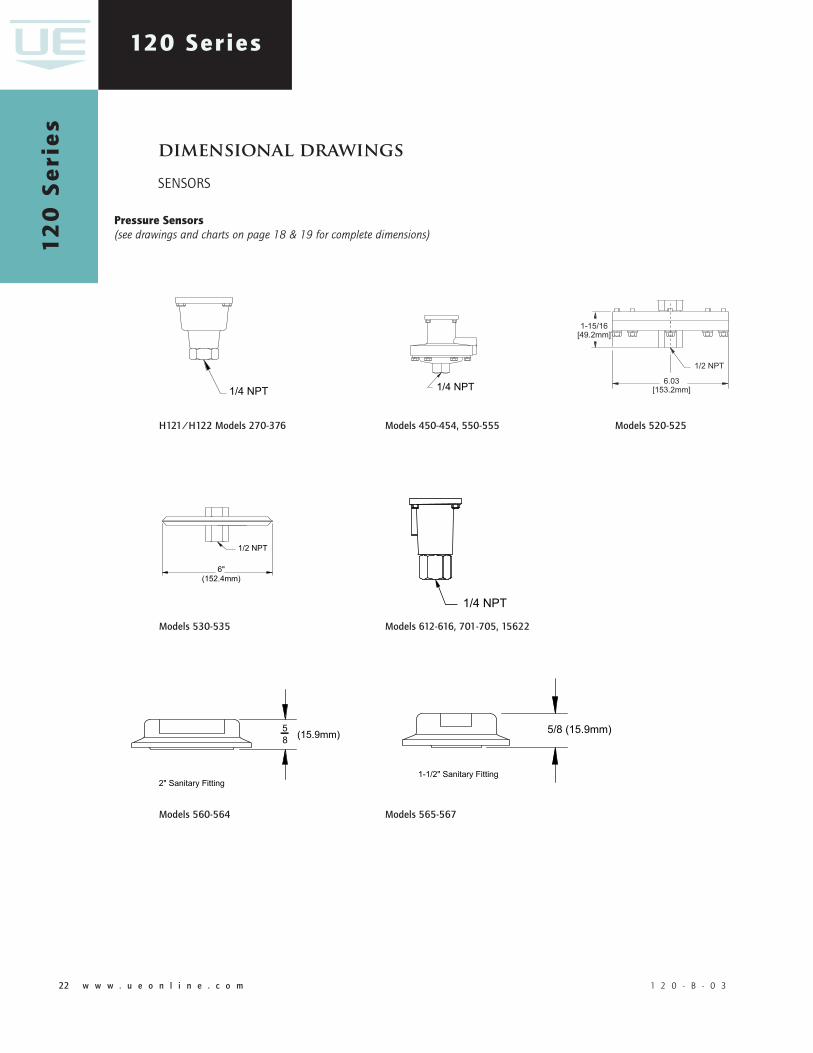
120 Series
pressure Sensors (see drawings and charts on page 18 & 19 for complete dimensions)
dimensionaldrawings
SENSORS
Models12�-1��
Models1�3-1��,��3-��� Models1��-19�,���-�9� J120Models270-37�,��0
ModelsS12�B-S1��B Models171-17�
1 2 0 - B - 0 3 w w w . u e o n l i n e . c o m 2�22 w w w . u e o n l i n e . c o m 1 2 0 - B - 0 3
120 Series1
20
Se
rie
s
1 2 0 - B - 0 3 w w w . u e o n l i n e . c o m 2�22 w w w . u e o n l i n e . c o m 1 2 0 - B - 0 3
H121/H122Models270-37�
Models�12-�1�,701-705,15�22
Models�50-�5�,550-555
Models530-535
Models520-525
Models5�0-5�� Models5�5-5�7
pressure Sensors (see drawings and charts on page 18 & 19 for complete dimensions)
dimensionaldrawings
SENSORS

1 2 0 - B - 0 3 w w w . u e o n l i n e . c o m 2�22 w w w . u e o n l i n e . c o m 1 2 0 - B - 0 3 1 2 0 - B - 0 3 w w w . u e o n l i n e . c o m 2�22 w w w . u e o n l i n e . c o m 1 2 0 - B - 0 3
120 Series
differential pressure Sensors (see drawings and charts on page 18 & 19 for complete dimensions)
Models�55-�57,559
Models5��-5��Models5�0-5�3Models1�7-157
J120KModels3�-39
J120KModels3�7
ModelsS1�7B-S157B
dimensionaldrawings
SENSORS
Models1BS-�BSModels120-121
Temperature Sensors (see drawings and charts on page 18 and 19 for complete dimensions)

FGS5000406
U N I T E D E L E C T R I C C O N T R O L S
180 Dexter Avenue, P.O. Box 9143 Watertown, MA 02471-9143 USATelephone: 617 926-1000 Fax: 617 926-2568http://www.ueonline.com
REcommEndEd pRAcTicES And wARningS United Electric Controls Company recommends careful consideration of the following factors when specifying and installing UE pressure and temperature units. Before installing a unit, the Installation and Maintenance instructions provided with unit must be read and understood.
• To avoid damaging unit, proof pressure and maximum temperature limits stated in literature and on nameplates must never be exceeded, even by surges in the system. Operation of the unit up to maximum pressure or temperature is acceptable on a limited basis (e.g., start-up, testing) but continuous operation must be restricted to the designated adjustable range. Excessive cycling at maximum pressure or temperature limits could reduce sensor life.
• A back-up unit is necessary for applications where damage to a primary unit could endanger life, limb or property. A high or low limit switch is necessary for applications where a dangerous runaway condition could result.
• The adjustable range must be selected so that incorrect, inadvertent or malicious setting at any range point cannot result in an unsafe system condition.
• Install unit where shock, vibration and ambient temperature fluctuations will not damage unit or affect operation. When applicable, orient unit so that moisture does not enter the enclosure via the electrical connection. When appropriate, this entry point should be sealed to prevent moisture entry.
• Unit must not be altered or modified after shipment. Consult UE if modification is necessary.
• Monitor operation to observe warning signs of possible damage to unit, such as drift in set point or faulty display. Check unit immediately.
• Preventative maintenance and periodic testing is necessary for critical applications where damage could endanger property or personnel.
• Electrical ratings stated in literature and on nameplate must not be exceeded. Overload on a switch can cause damage, even on the first cycle. Wire unit according to local and national electrical codes, using wire size recommended in installation sheet.
• Do not mount unit in ambient temp. exceeding published limits.
limiTEd wARRAnTySeller warrants that the product hereby purchased is, upon delivery, free from defects in material and workmanship and that any such product which is found to be defective in such workmanship or material will be repaired or replaced by Seller (Ex-works, Factory, Watertown, Massachusetts. INCOTERMS); provided, however, that this warranty applies only to equipment found to be so defective within a period of 24 months from the date of manufacture by the Seller. Seller shall not be obligated under this warranty for alleged defects which examination discloses are due to tampering, misuse, neglect, improper storage, and in any case where products are disassembled by anyone other than authorized Seller’s representatives. EXCEPT FOR THE LIMITED WARRANTy OF REPAIR AND REPLACEMENT STATED ABOVE, SELLER DISCLAIMS ALL WARRANTIES WHATSOEVER WITH RESPECT TO THE PRODUCT, INCLUDING ALL IMPLIED WARRANTIES OF MERCHANTABILITy OR FITNESS FOR ANy PARTICULAR PURPOSE.
limiTATion oF SEllER’S liAbiliTySELLER’S LIABILITy TO BUyER FOR ANy LOSS OR CLAIM, INCLUDING LIABILITy INCURRED IN CONNECTION WITH (I) BREACH OF ANy WARRANTy WHATSOEVER, EXPRESSED OR IMPLIED, (II) A BREACH OF CONTRACT, (III) A NEGLIGENT ACT OR ACTS (OR NEGLIGENT FAILURE TO ACT) COMMITTED By SELLER, OR (IV) AN ACT FOR WHICH STRICT LIABILITy WILL BE INPUTTED TO SELLER, IS LIMITED TO THE “LIMITED WARRANTy” OF REPAIR AND/OR REPLACEMENT AS SO STATED IN OUR WARRANTy OF PRODUCT. IN NO EVENT SHALL THE SELLER BE LIABLE FOR ANy SPECIAL, INDIRECT, CONSEQUENTIAL OR OTHER DAMAGES OF A LIKE GENERAL NATURE, INCLUDING, WITHOUT LIMI-TATION, LOSS OF PROFITS OR PRODUCTION, OR LOSS OR EXPENSES OF ANy NATURE INCURRED By THE BUyER OR ANy THIRD PARTy.
UE specifications subject to change without notice.
inTERnATionAl oFFicES
CHINA United Electric Controls Room 1114, No. 511 Shenshi Building Weihai Road Shanghai 200041, P.R. China Phone: +8621-6255 8059 email: [email protected]
EASTERN EUROPE & SCANDINAVIA United Electric Controls 05-806 Komorow Kujawska 5, Poland Phone: +48 22 499 4804 email: [email protected]
GERMANy United Electric Controls An Der Zentlinde 21 D-64711 Erbach, Germany Phone: 496-062-7400 email: [email protected]
MALAySIA United Electric Controls, Far East No. 1-2-2, 2nd Floor Jalan 4/101C Cheras Business Centre Batu 5, Jalan Cheras 56100 Kuala Lumpur, Malaysia Phone: 603-9133-4122 email: [email protected]
MEXICO United Electric Controls Andador Austria 102 Fracc. Petroquimica CP 89365 Tampico, Tamaulipas Mexico Phone: 833-132-3726 email: [email protected]
RUSSIA United Electric Controls, Moscow Kuusinena str., 19A, Office 310 Moscow, 125252, Russia Phone: +7 (095) 792-88-06 email: [email protected]
U.S. SAlES oFFicES
United Electric Controls 31 Old Stage Road Hampton Falls, NH 03844 Phone: 617-899-1132 email: [email protected]
United Electric Controls 28 N. Wise Ave. Freeport, IL 61032 Phone: 815-341-2588 email: [email protected]
United Electric Controls 1022 Vineyard Drive Conyers, GA 30013 Phone: 770-335-9802 email: [email protected]
United Electric Controls 5829 Grazing Court Mason, OH 45040 Phone: 513-535-5486 email: [email protected]
United Electric Controls 102 Salazar Court Clayton, CA 94517 Phone: 925-408-5997 email: [email protected]
United Electric Controls 27 Summit Terrace Sparta, NJ 07871 Phone: 973-271-2550 email: [email protected]
United Electric Controls 4306 Whickham Drive Fulshear, TX 77441 Phone: 832-457-6138 email: [email protected]
United Electric Controls 5201 Arbor Court Odessa, TX 79762 Phone: 432-770-4164 email: [email protected]
cAnAdA
EASTERN 68 Mosley Crescent Brampton, Ontario Canada L6y 5C8 Phone: 905-455-5131 FAX: 905-455-5131
WESTERN 148 Silver Ridge Close N.W. Calgary, Alberta Canada T3B 3T4 Phone: 403-247-3724 FAX: 403-247-3724


![Honeywell Pressure SwitchesHoneywell Pressure Switches High Pressure: HP Series, HE Series Factory set 150 psi to 4500 psi [10,34 bar to 310,26 bar] Low Pressure: LP Series, LE Series](https://img.pdfslide.net/doc/110x75/60ad806272620b5c0e1b1975/honeywell-pressure-switches-honeywell-pressure-switches-high-pressure-hp-series.jpg)