Embed Size (px)
Citation preview
Specifications of the vessel and the gas installations are believed
to be correct, but not guaranteed.
INDEX
GENERAL INFORMATION PAGE
A1 Principal Ship Particulars 2-3
A2 Hull Dimensions 4
A3 Immersion 4
A4 Loaded Particulars 4-5
A5 Parallel Mid-Body Dimensions 6
A6 Bunker Specifications and Capacities 6
A7 Fuel Consumption Details 6
A7 Speed/Consumption (Appendix) 7
A8 Main Engine Particulars 7
A9 Auxiliary Plants 7
A10 Power/Speed Information 7
A11 Thrusters 7
A12 Fresh Water 7
A13 Ballast Capacities and Pumps 8
A14 Mooring Equipment 8-10
A15 Navigational Equipment 10-11
A16 Communication and Electronics 11
12,000 M3 LEG/LPG/NH3/VCM
CARRIER (ELETSON)
GAS FORM-Cbased on the
OCIMF / SIGTTOSHIP INFORMATION QUESTIONNAIRE
for
GAS CARRIERS2nd Edition 1998
HHI Version12/2004 -YSL
Page 0
HHI - Gas Form-C
CARGO SYSTEMS
B1 Cargo - General Information 12
B2 Cargo Tanks 12
B3 Cargo Tank Capacities 13-15
B16 Deck Tank Capacities 15-16
B4 Loading Rates 16-17
B5 Discharging - General 17-18
B6 Discharge Performance 18
B7 Unpumpables 18
B8 Vaporising Unpumpables 18
B9 Reliquefaction Plant 18-19
B10 Section not in use.
B11 Cargo Temperature Lowering Capability 19
B12 Inert Gas and Nitrogen 19-20
B13 Cargo Tank Inerting / De-Inerting 20
B14 Gas Freeing to Fresh Air 20
B15 Changing Cargo Grades 20-21
B17 Pre-Loading Cooldown 21-22
B18 Vaporiser 22
B19 Blower 22
B20 Cargo Re-Heater 22
B21 Hydrate Control 22
B22 Cargo Measurement 22-23
B23 Cargo Sampling 23
B24 Cargo Manifold 24-25
B25 Cargo Manifold Reducers 25-26
B26 Connections to Shore for ESD and Communication Systems 26
B27 Manifold Derrick/Crane 26
B28 Stores Derrick/Crane
B29 Sister Vessel(s)
SECTION A
GENERAL INFORMATION
A1 PRINCIPAL SHIP PARTICULARS
1,1 Date questionnaire completed 16-11-2015
1,2 Name of vessel LPG/C PAROS
1,3 LR/IMO number 9711511
1,4 Last previous name N/A
1.4.1 Date of name change N/A
1,5 Second last previous name N/A
1.5.1 Date of name change N/A
1,6 Third last previous name N/A
1.6.1 Date of name change N/A
1,7 Fourth last previous name N/A
1.7.1 Date of name change N/A
1,8 Flag GREEK
1,9 Port of Registry Piraeus
1.10 Official number
1,11 Call sign SVCE4
1,12 INMARSAT A or B number N/A
1,13 Vessel's telephone number
1.13.1 Vessel's mobile number
1,14 Vessel's fax number
1,15 Vessel’s telex number
1,16 Vessel's E-mail address
37257786269
783156721
000870773930060//02112340053 (Bridge) -
02112340052 (Master)
HHI Version12/2004 -YSL
Page 1
HHI - Gas Form-C
1,17 INMARSAT C number
1,18 Vessel's MMSI number
1,19 Type of vessel LEG/LPG/NH3/VCM Carrier
Max tank pressure 5.0 Barg (0.972 t/m3)
Min temp -104oC
OWNERSHIP AND OPERATION
1.20 Registered Owner PAROS SPECIAL MARITIME ENTERPRISE
Full address c/o Eletson Corporation
118, Kolokotroni Street
GR 185 35 Piraeus
Greece
Office telephone number 30 2104282300
Office telex number 217424 - EletGR
Office fax number 30 210 428 2320
Office Email address [email protected]
Contact person Cpt Antonios Michail
Contact person after hours telephone number
1.21 Name of technical operator (If different from above) As Above
Full Address
Office telephone number
Office telex number
Office fax number
Office Email address
Contact person (Designated Person Ashore)
Contact person after hours telephone number
Emergency callout number
Emergency callout pager number
Contact details for person responsible for oil spill response
Number of years controlled by technical operator Since Delivery Years
1.22 Total number of ships operated by this Operator 32
1.23 Number of years ship owned Since Delivery Years
1.23.1 Name of commercial operator (If different from above) As Above
Full Address
Office telephone number
Office telex number
Office fax number
Office Email address
Contact person
Contact person after hours telephone number
Emergency callout number
Emergency callout pager number
Number of years controlled by commercial operator Since Delivery Years
BUILDER
1.24 Builder Hyundai Mipo Dockyard
1.25 Name of yard vessel built at HMD
1.26 Hull number 8165
1.27 Date keel laid 8-Jun-15
1.28 Date launched 10-Aug-15
1.29 Date delivered
1.30 Date of completion of major hull changes, - if any. N/A
1.31 If changes were made, what changes were made and at
which yard were they carried out
N/A
241388000
424100069 (LRIT)
+30 6946502363
HHI Version12/2004 -YSL
Page 2
HHI - Gas Form-C
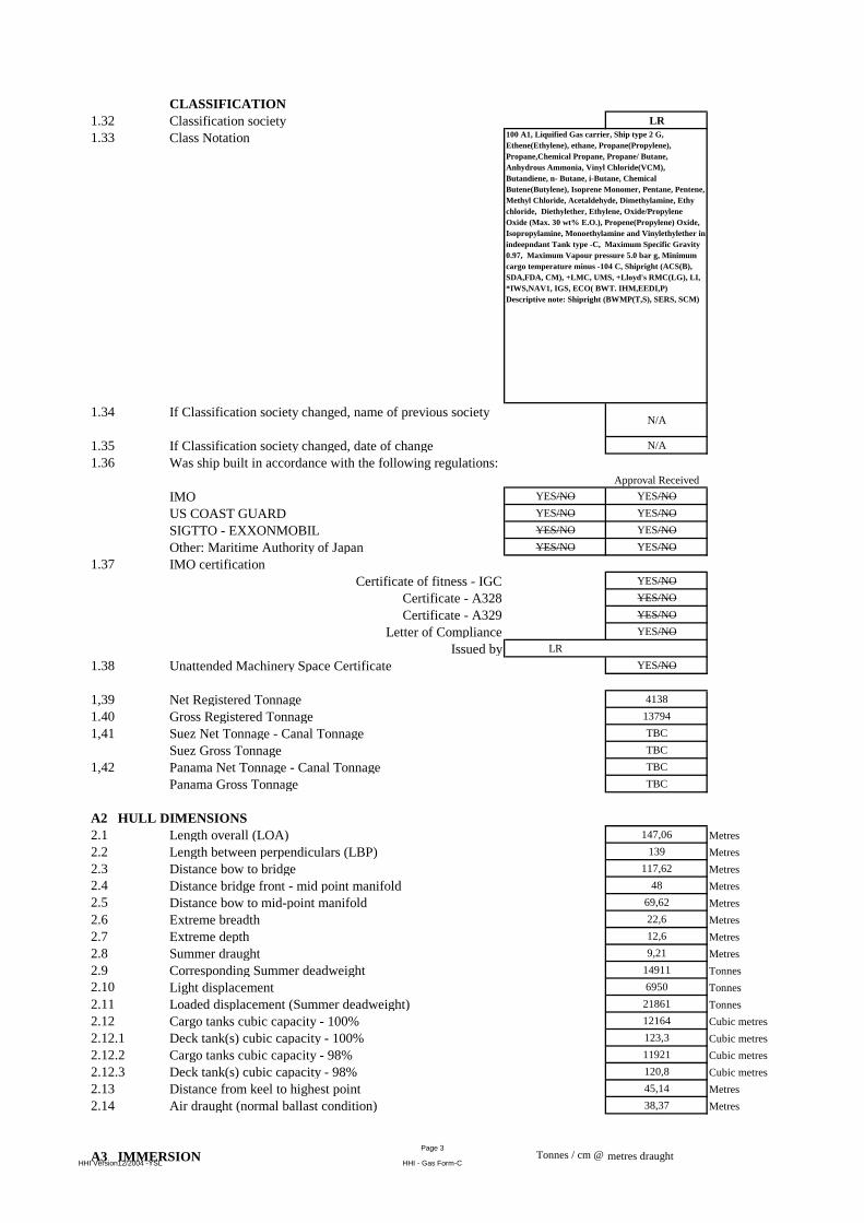
CLASSIFICATION
1.32 Classification society LR
1.33 Class Notation
1.34 If Classification society changed, name of previous societyN/A
1.35 If Classification society changed, date of change N/A
1.36 Was ship built in accordance with the following regulations:
Approval Received
IMO YES/NO YES/NO
US COAST GUARD YES/NO YES/NO
SIGTTO - EXXONMOBIL YES/NO YES/NO
Other: Maritime Authority of Japan YES/NO YES/NO
1.37 IMO certification
Certificate of fitness - IGC YES/NO
Certificate - A328 YES/NO
Certificate - A329 YES/NO
Letter of Compliance YES/NO
Issued by LR
1.38 Unattended Machinery Space Certificate YES/NO
1,39 Net Registered Tonnage 4138
1.40 Gross Registered Tonnage 13794
1,41 Suez Net Tonnage - Canal Tonnage TBC
Suez Gross Tonnage TBC
1,42 Panama Net Tonnage - Canal Tonnage TBC
Panama Gross Tonnage TBC
A2 HULL DIMENSIONS
2.1 Length overall (LOA) 147,06 Metres
2.2 Length between perpendiculars (LBP) 139 Metres
2.3 Distance bow to bridge 117,62 Metres
2.4 Distance bridge front - mid point manifold 48 Metres
2.5 Distance bow to mid-point manifold 69,62 Metres
2.6 Extreme breadth 22,6 Metres
2.7 Extreme depth 12,6 Metres
2.8 Summer draught 9,21 Metres
2.9 Corresponding Summer deadweight 14911 Tonnes
2.10 Light displacement 6950 Tonnes
2.11 Loaded displacement (Summer deadweight) 21861 Tonnes
2.12 Cargo tanks cubic capacity - 100% 12164 Cubic metres
2.12.1 Deck tank(s) cubic capacity - 100% 123,3 Cubic metres
2.12.2 Cargo tanks cubic capacity - 98% 11921 Cubic metres
2.12.3 Deck tank(s) cubic capacity - 98% 120,8 Cubic metres
2.13 Distance from keel to highest point 45,14 Metres
2.14 Air draught (normal ballast condition) 38,37 Metres
A3 IMMERSION Tonnes / cm @ metres draught
100 A1, Liquified Gas carrier, Ship type 2 G,
Ethene(Ethylene), ethane, Propane(Propylene),
Propane,Chemical Propane, Propane/ Butane,
Anhydrous Ammonia, Vinyl Chloride(VCM),
Butandiene, n- Butane, i-Butane, Chemical
Butene(Butylene), Isoprene Monomer, Pentane, Pentene,
Methyl Chloride, Acetaldehyde, Dimethylamine, Ethy
chloride, Diethylether, Ethylene, Oxide/Propylene
Oxide (Max. 30 wt% E.O.), Propene(Propylene) Oxide,
Isopropylamine, Monoethylamine and Vinylethylether in
indeepndant Tank type -C, Maximum Specific Gravity
0.97, Maximum Vapour pressure 5.0 bar g, Minimum
cargo temperature minus -104 C, Shipright (ACS(B),
SDA,FDA, CM), +LMC, UMS, +Lloyd's RMC(LG), LI,
*IWS,NAV1, IGS, ECO( BWT. IHM,EEDI,P)
Descriptive note: Shipright (BWMP(T,S), SERS, SCM)
HHI Version12/2004 -YSL
Page 3
HHI - Gas Form-C
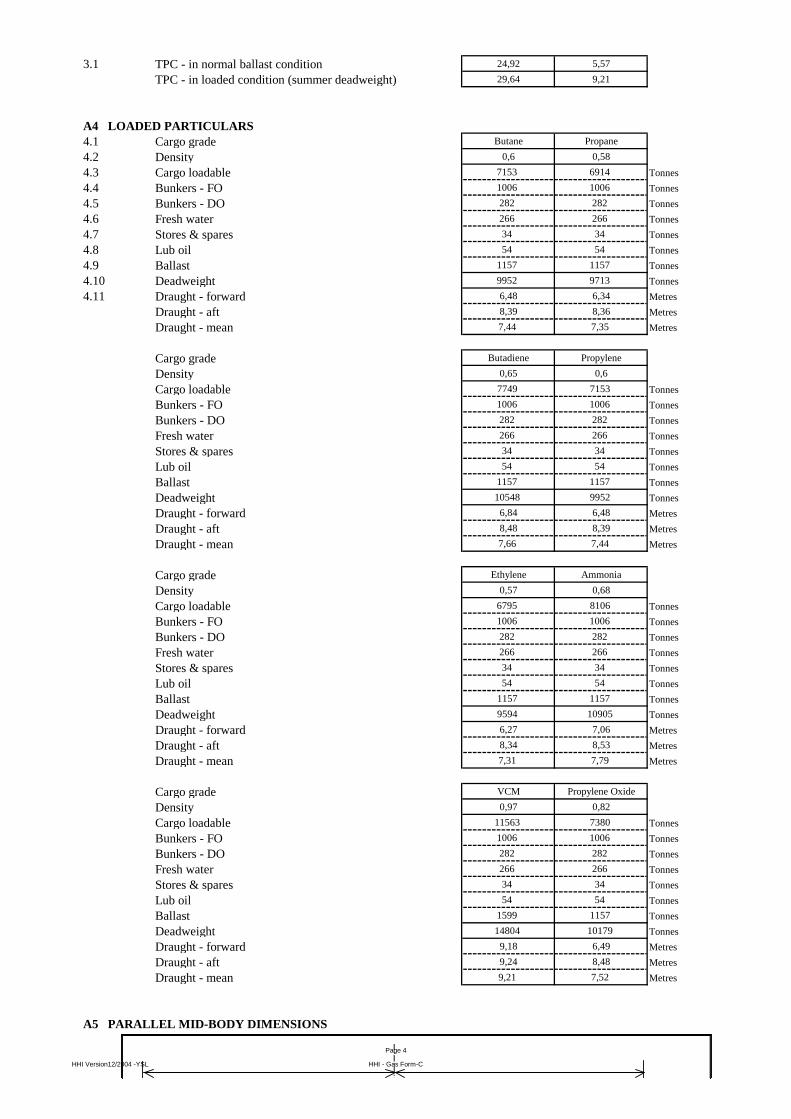
3.1 TPC - in normal ballast condition 24,92 5,57
TPC - in loaded condition (summer deadweight) 29,64 9,21
A4 LOADED PARTICULARS
4.1 Cargo grade Butane Propane
4.2 Density 0,6 0,58
4.3 Cargo loadable 7153 6914 Tonnes
4.4 Bunkers - FO 1006 1006 Tonnes
4.5 Bunkers - DO 282 282 Tonnes
4.6 Fresh water 266 266 Tonnes
4.7 Stores & spares 34 34 Tonnes
4.8 Lub oil 54 54 Tonnes
4.9 Ballast 1157 1157 Tonnes
4.10 Deadweight 9952 9713 Tonnes
4.11 Draught - forward 6,48 6,34 Metres
Draught - aft 8,39 8,36 Metres
Draught - mean 7,44 7,35 Metres
Cargo grade Butadiene Propylene
Density 0,65 0,6
Cargo loadable 7749 7153 Tonnes
Bunkers - FO 1006 1006 Tonnes
Bunkers - DO 282 282 Tonnes
Fresh water 266 266 Tonnes
Stores & spares 34 34 Tonnes
Lub oil 54 54 Tonnes
Ballast 1157 1157 Tonnes
Deadweight 10548 9952 Tonnes
Draught - forward 6,84 6,48 Metres
Draught - aft 8,48 8,39 Metres
Draught - mean 7,66 7,44 Metres
Cargo grade Ethylene Ammonia
Density 0,57 0,68
Cargo loadable 6795 8106 Tonnes
Bunkers - FO 1006 1006 Tonnes
Bunkers - DO 282 282 Tonnes
Fresh water 266 266 Tonnes
Stores & spares 34 34 Tonnes
Lub oil 54 54 Tonnes
Ballast 1157 1157 Tonnes
Deadweight 9594 10905 Tonnes
Draught - forward 6,27 7,06 Metres
Draught - aft 8,34 8,53 Metres
Draught - mean 7,31 7,79 Metres
Cargo grade VCM Propylene Oxide
Density 0,97 0,82
Cargo loadable 11563 7380 Tonnes
Bunkers - FO 1006 1006 Tonnes
Bunkers - DO 282 282 Tonnes
Fresh water 266 266 Tonnes
Stores & spares 34 34 Tonnes
Lub oil 54 54 Tonnes
Ballast 1599 1157 Tonnes
Deadweight 14804 10179 Tonnes
Draught - forward 9,18 6,49 Metres
Draught - aft 9,24 8,48 Metres
Draught - mean 9,21 7,52 Metres
A5 PARALLEL MID-BODY DIMENSIONS
Load
Draft
Ballast
Draft
Light
Ship
C/L
HHI Version12/2004 -YSL
Page 4
HHI - Gas Form-C
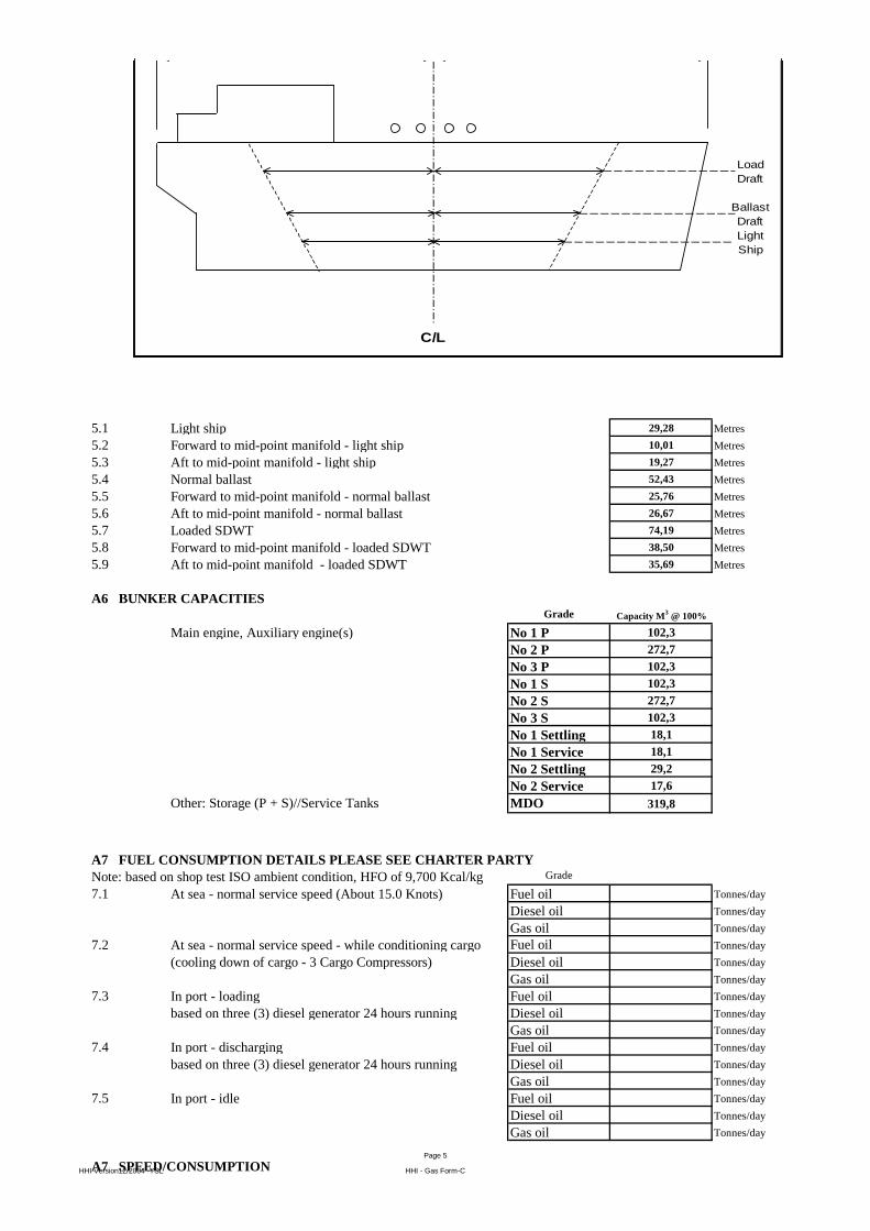
5.1 Light ship 29,28 Metres
5.2 Forward to mid-point manifold - light ship 10,01 Metres
5.3 Aft to mid-point manifold - light ship 19,27 Metres
5.4 Normal ballast 52,43 Metres
5.5 Forward to mid-point manifold - normal ballast 25,76 Metres
5.6 Aft to mid-point manifold - normal ballast 26,67 Metres
5.7 Loaded SDWT 74,19 Metres
5.8 Forward to mid-point manifold - loaded SDWT 38,50 Metres
5.9 Aft to mid-point manifold - loaded SDWT 35,69 Metres
A6 BUNKER CAPACITIESGrade Capacity M
3 @ 100%
Main engine, Auxiliary engine(s) No 1 P 102,3
No 2 P 272,7
No 3 P 102,3
No 1 S 102,3
No 2 S 272,7
No 3 S 102,3
No 1 Settling 18,1
No 1 Service 18,1
No 2 Settling 29,2
No 2 Service 17,6
Other: Storage (P + S)//Service Tanks MDO 319,8
A7 FUEL CONSUMPTION DETAILS PLEASE SEE CHARTER PARTY
Note: based on shop test ISO ambient condition, HFO of 9,700 Kcal/kg Grade
7.1 At sea - normal service speed (About 15.0 Knots) Fuel oil Tonnes/day
Diesel oil Tonnes/day
Gas oil Tonnes/day
7.2 At sea - normal service speed - while conditioning cargo Fuel oil Tonnes/day
(cooling down of cargo - 3 Cargo Compressors) Diesel oil Tonnes/day
Gas oil Tonnes/day
7.3 In port - loading Fuel oil Tonnes/day
based on three (3) diesel generator 24 hours running Diesel oil Tonnes/day
Gas oil Tonnes/day
7.4 In port - discharging Fuel oil Tonnes/day
based on three (3) diesel generator 24 hours running Diesel oil Tonnes/day
Gas oil Tonnes/day
7.5 In port - idle Fuel oil Tonnes/day
Diesel oil Tonnes/day
Gas oil Tonnes/day
A7 SPEED/CONSUMPTION
Load
Draft
Ballast
Draft
Light
Ship
C/L
HHI Version12/2004 -YSL
Page 5
HHI - Gas Form-C
Copies of the vessel's Speed and Consumption Graph for
both Laden and Ballast conditions are enclosed?NO
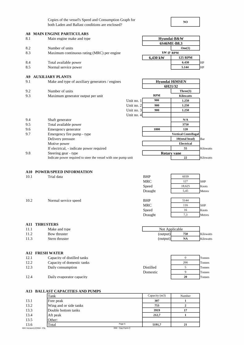
A8 MAIN ENGINE PARTICULARS
8.1 Main engine make and type
8.2 Number of units One(1)
8.3 Maximum continuous rating (MRC) per engine kW @ RPM
6,430 kW 125 RPM
8.4 Total available power 6.430 HP
8.5 Normal service power 5.144 HP
A9 AUXILIARY PLANTS
9.1 Make and type of auxiliary generators / engines
9.2 Number of units Three(3)
9.3 Maximum generator output per unit RPM Kilowatts
Unit no. 1 900 1.250
Unit no. 2 900 1.250
Unit no. 3 900 1.250
Unit no. 4
9.4 Shaft generator N/A
9.5 Total available power 3750
9.6 Emergency generator 1800 120
9.7 Emergency fire pump - type Vertical Centrifugal
Delivery pressure 10(total head) Bar
Motive power Electrical
If electrical, - indicate power required 55 Kilowatts
9.8 Steering gear - typeIndicate power required to steer the vessel with one pump unit 22 Kilowatts
A10 POWER/SPEED INFORMATION
10.1 Trial data BHP 6039
MRC 127 SHP
Speed 18,625 Knots
Draught 5,45 Metres
10.2 Normal service speed BHP 5144
MRC 116 SHP
Speed 16 Knots
Draught 7,3 Metres
A11 THRUSTERS
11.1 Make and type
11.2 Bow thruster (output) 750 Kilowatts
11.3 Stern thruster (output) NA Kilowatts
A12 FRESH WATER
12.1 Capacity of distilled tanks 0 Tonnes
12.2 Capacity of domestic tanks 266 Tonnes
12.3 Daily consumption Distilled 5 Tonnes
Domestic 9 Tonnes
12.4 Daily evaporator capacity 20 Tonnes
A13 BALLAST CAPACITIES AND PUMPS
Tank Capacity (m3) Number
13.1 Fore peak 307 1
13.2 Wing and or side tanks 753 2
13.3 Double bottom tanks 3919 17
13.4 Aft peak 212,7 1
13.5 Other:
13.6 Total 5191,7 21
Rotary vane
Not Applicable
Hyundai-B&W
6S46ME-B8.3
Hyundai HiMSEN
6H21/32
HHI Version12/2004 -YSL
Page 6
HHI - Gas Form-C
13.7 Ballast pump make and type
13.8 Number of pumps 2
13.9 Total capacity 300 M3/hour
13.10 Location E/room (Floor)
13.11 Control location PUMP SIDE/ CCR//ECR
A14 MOORING EQUIPMENT
14.1 ROPES
Indicate on the diagram below the position of:
Winch Mounted Ropes (R)
Open Fairleads (O)
Alternatively enclosed copy of vessel's Mooring
arrangements in A4 format.
MOORING ROPES (ON DRUMS)
Mooring Ropes (On Drums) Forecastle - Number 4
Diameter 38 mm.
Material
Length 200 Metres
Breaking Strength 38,5 Tonnes
Mooring Ropes (On Drums) Forward Main Deck - Number 2
Diameter 38 mm.
Material
Length 200 Metres
Breaking Strength 38,5 Tonnes
Mooring Ropes (On Drums) Aft Main Deck - Number
Diameter mm.
Material
Length Metres
Breaking Strength Tonnes
Mooring Ropes (On Drums) Poop - Number 4
Diameter 38 mm.
Material
Length 200 Metres
Breaking Strength 38,5 Tonnes
OTHER MOORING LINES
Mooring Ropes not on Drums - Number 8
Diameter 38 mm.
Material
Length 200 Metres
Breaking Strength 38,5 Tonnes
Emergency Towing Wires / Fire Wires - Number 2
Diameter 28 mm.
Material
Length 45 Metres
Breaking Strength 3425 Tonnes
14,2 MOORING WINCHES
Forecastle - Number 2
Single Drum or Double Drums Double
Split Drums Y/N YES
FIRE WIRES : GALVANIXED STEEL
Closed Fairleads (C) _ APPLICATION OF CLOSED CHOCK
50/50 POLYESTER/POLYSTEEL
50/50 POLYESTER/POLYSTEEL
50/50 POLYESTER/POLYSTEEL
Electric
50/50 POLYESTER/POLYSTEEL
HHI Version12/2004 -YSL
Page 7
HHI - Gas Form-C
Motive Power El-Hydraulic
Heaving Power 12 Tonnes
Brake Capacity 38,5 Tonnes
Hauling Speed 15 Metres/Min.
Forward Main Deck - Number 1
Single Drum or Double Drums Double
Split Drums Y/N YES
Motive Power El-Hydraulic
Heaving Power 12,5 Tonnes
Brake Capacity 38,5 Tonnes
Hauling Speed 15 Metres/Min.
Aft Main Deck - Number N/A
Single Drum or Double Drums
Split Drums Y/N
Motive Power
Heaving Power Tonnes
Brake Capacity Tonnes
Hauling Speed Metres/Min.
Poop - Number 2
Single Drum or Double Drums Double
Split Drums Y/N YES
Motive Power El-Hydraulic
Heaving Power 12,5 Tonnes
Brake Capacity 38,5 Tonnes
Hauling Speed 15 Metres/Min.
14.3 ANCHORS AND WINDLASS
Windlass motive power(e.g. steam, hydraulic)
Hauling power 16,3 Tonnes
Brake holding power 119,2 Tonnes
Anchor type
Weight 4,33 Tonnes
Is spare anchor carried NO
Cable diameter 58 mm.
Number of shackles port cable 11
Number of shackles starboard cable 10
14,4 TOWING ARRANGEMENTS
Is the vessel fitted with a Towing Bracket Aft? N/A
If Yes, state SWL Tonnes
Is Towing chain provided N/A
Dimensions of Towing wire Diameter mm.
Length Metres
14.5 WINDAGE
Windage on ballast draught End-on 530 Squaremetres
Lateral 1936 Squaremetres
A15 NAVIGATIONAL EQUIPMENT
15.1 Magnetic compass YES/NO
15.2 Off Course Alarm - Magnetic compass YES/NO
15.3 Gyro compass YES/NO
Number of Units 2
15.4 Off Course Alarm - Gyro compass YES/NO
15.5 Gyro (Bridge) Repeaters YES/NO
Number of Units 5
15.6 Radar 3cm YES/NO
15.7 Radar 10cm YES/NO
15.8 Are radars gyro stabilised? YES/NO
15.9 Radar plotting equipment YES/NO
15.10 ARPA YES/NO
15.11 ECDIS YES/NO
15.12 Depth sounder with recorder YES/NO
Stockless High Holding Power
Electro-Hydraulic
HHI Version12/2004 -YSL
Page 8
HHI - Gas Form-C
15.13 Depth sounder without recorder YES/NO
15.14 Speed/distance indicator YES/NO
15.15 Doppler log YES/NO
15.16 Docking approach Doppler YES/NO
15.17 Rudder angle indicator YES/NO
15.18 Rudder angle indicator on Each Bridge Wing YES/NO
15.19 RPM indicator YES/NO
15.20 RPM indicator on Each Bridge Wing YES/NO
15.21 Controllable pitch propeller indicator YES/NO/NA
15.22 Thruster(s) indicator YES/NO
15.23 Rate of turn indicator YES/NO
15.24 Radio direction finder YES/NO
15.25 Navtex receiver YES/NO
15.26 GPS YES/NO
15.26.1 DGPS YES/NO
15.27 Transit SATNAV YES/NO
15.28 Decca navigator YES/NO
15.29 Omega YES/NO
15.30 Loran C YES/NO
15.31 Weather fax YES/NO
15.32 Sextant(s) YES
15.33 Signal lamp ALDIS YES/NO
15.34 Anemometer YES/NO
15.35 Engine order recorder YES/NO
15.35.1 VDR (Voyage Data Recorder) YES/NO
15.36 Course recorder YES/NO
15.37 Are steering motor controls and engine controls fitted on
bridge wings?YES/NO
15.38 Is bridge equipped with a 'Dead-Man' alarm? YES/NO/NA
15.39 What chart outfit coverage is provided World-wide YES/NO
Limited YES/NO
If limited, - please indicate area(s) covered N/A
15.40 Formal chart correction system in use YES/NO
15.41 Electronic Chart system in use YES/NO
A16 COMMUNICATIONS AND ELECTRONICS
16.2 What GMDSS areas is the vessel classed for? A1 A2 A3 A4A1+A2+A3
16.3 Transponder (SART) YES/NO
16.4 EPIRB YES/NO
16.5 How many VHF radios are fitted on the bridge? 2
16.6 Is vessel fitted with VHF in the cargo control room (CCR)?YES/NO
16.7 Is the CCR connected to the vessel's internal communication
system?YES/NO
16.8 How many intrinsically safe walkie talkies are provided for
cargo handling?11
16.9 Is vessel fitted with an INMARSAT satellite
communications system?YES/NO
16.10 Does vessel carry at least three survival craft two-way radio
telephones?YES/NO
16.11 Inmarsat satellite system YES/NO
Specify system type A, B or C FBB 500
16.12 2182kHz bridge auto alarm YES/NO
16.13 Radio telephone distress frequency watch receiver YES/NO
16.14 Emergency lifeboat transceiver YES/NO
16.15 Can vessel transmit the helicopter homing signal on 410
kHz?YES/NO
16.16 Full set of Radio List publications YES/NO
SECTION B
CARGO SYSTEMS
B1 CARGO - GENERAL INFORMATIONHHI Version12/2004 -YSL
Page 9
HHI - Gas Form-C
1.1 List products which the ship is Certified to carry
Transport and Carriage Conditions
1.2 Minimum allowable tank temperature -104 Deg. Celsius
1.3 Maximum Permissible tank pressure 5 Bar g
1.4 List Number of grades that can be loaded/discharged
simultaneously and completely segregated without risk of
contamination?
2
1.5 List the Number of grades that can be carried simultaneously
and completely segregated without risk of contamination? 2
1.6 What is the Number of Products that can be conditioned by
reliquefaction simultaneously?2
1.7 State the number of natural segregation's (NB: Separation
must be by the removal of spools or the insertion of blanks) 2
B2 CARGO TANKS
2.1 Type and materials of cargo tanks Independent
Type C
(cylindrical)
Low temperature,
5% Ni-steel, X12Ni5
2.2 Maximum allowable relief valve setting 5 Bar gauge
2.2.1 IMO Setting 5 Bar gauge
2.2.2 USCG Setting 5 Bar gauge
2.3 Safety valve set pressure, - if variable stipulate range of pilot
valves5
Bar gauge
2.4 Maximum allowable vacuum 0,75 Bar abs
2.5 Maximum cargo density at 15 deg Celsius 972 kg/m³
2.6 Maximum rate of cool-down 10 Deg Cel / Hour
2.7 State any limitations regarding partially filled tanks no
2.8 State allowable combinations of filled and empty tanks
B3 CARGO TANK CAPACITIES
Tank number / location Tank 1/ Fore
Capacity m3 (100%) 4057 m3
Capacity 98% 3976 m3
Butane capacity 2386 Tonnes
Butane temperature 0 Deg. C
Propane capacity 2306 Tonnes
Propane temperature -42 Deg. C
Butadiene capacity 2584 Tonnes
Ethylene, Ethane, Propylene, Propane, Commercial Propane ( max ethane content 5% ),
No.1 (2+3 empty); No.2(1+3 empty); No.3 (1+2 empty); Nos. 1+2 (No. 3 empty);
Propane/Butane mix, Anhydrous ammonia, Vinyl chloride manomer (VCM),
Butadiene, n-Butane, i-Butane, Commercial butane (n-Butane/i-Butane mix),
Methyl Chloride, Mixed C4, Acetaldehyde, Dimethylamine, Ethyl Chloride,
Nos. 1+3 (No. 2 empty); Nos. 2+3 (No 1 empty)
There are no limitations for partial filling ratio
Diethyl Ether, Ethylene Oxide/Propylene Oxide (max 30 % wt E.O.),
Propylene Oxide, Isoprene (monomer), Pentane, Pentene, Isopropylamine,
Monoethylamine, Vinylethylether
Diethylether, Etylene Oxide/Propylene Oxide, Isopropylamine, Monoethylamine,
Vinylethylether max. 3000 m³ per cargo tank
HHI Version12/2004 -YSL
Page 10
HHI - Gas Form-C
Butadiene temperature -4 Deg. C
Propylene capacity 2386 Tonnes
Propylene temperature -48 Deg. C
Vinyl Chloride Monomer capacity 3857 Tonnes
Vinyl Chloride Monomer temperature -14 Deg. C
Ethylene capacity 2266,32 Tonnes
Ethylene temperature -103,4 Deg. C
Propylene Oxide capacity 2460 Tonnes
Propylene Oxide temperature 24 Deg. C
Ammonia capacity 2704 Tonnes
Ammonia temperature -33,5 Deg. C
Tank number / location Tank 2/ Mid.
Capacity m3 (100%) 4051 m3
Capacity 98% 3970 m3
Butane capacity 2382 Tonnes
Butane temperature 0 Deg. C
Propane capacity 2303 Tonnes
Propane temperature -42 Deg. C
Butadiene capacity 2581 Tonnes
Butadiene temperature -4 Deg. C
Propylene capacity 2382 Tonnes
Propylene temperature -48 Deg. C
Vinyl Chloride Monomer capacity 3851 Tonnes
Vinyl Chloride Monomer temperature -14 Deg. C
Ethylene capacity 2262,9 Tonnes
Ethylene temperature -103,4 Deg. C
Propylene Oxide capacity 2460 Tonnes
Propylene Oxide temperature 24 Deg. C
Ammonia capacity 2700 Tonnes
Ammonia temperature -33,5 Deg. C
Tank number / location Tank 3/ Aft
Capacity m3 (100%) 4057 m3
Capacity 98% 3976 m3
Butane capacity 2386 Tonnes
Butane temperature 0 Deg. C
Propane capacity 2306 Tonnes
Propane temperature -42 Deg. C
Butadiene capacity 2584 Tonnes
Butadiene temperature -4 Deg. C
Propylene capacity 2386 Tonnes
Propylene temperature -48 Deg. C
Vinyl Chloride Monomer capacity 3857 Tonnes
Vinyl Chloride Monomer temperature -14 Deg. C
Ethylene capacity 2266,32 Tonnes
Ethylene temperature -103,4 Deg. C
Propylene Oxide capacity 2460 Tonnes
Propylene Oxide temperature 24 Deg. C
Ammonia capacity 2704 Tonnes
Ammonia temperature -33,5 Deg. C
Total Capacity of all cargo tanks (100%) 12141 m3
Total Capacity of all cargo tanks (98%) 11898 m3
Total Capacity of Butane 7130 Tonnes
Total Capacity of Propane 6915 Tonnes
Total Capacity of Butadiene 7749 Tonnes
Total Capacity of Propylene 7153 Tonnes
Total Capacity of Vinyl Chloride Monomer 11564 Tonnes
Total Capacity of Ethylene 6782 Tonnes
Total Capacity of Propylene Oxide 7380 Tonnes
Total Capacity of Ammonia 8107 Tonnes
B16 DECK TANK CAPACITIES
Are Deck pressure tank(s) fitted? YESHHI Version12/2004 -YSL
Page 11
HHI - Gas Form-C
Material of tank(s) X12 Ni5
Maximum allowable relief valve setting 18 Bar gauge
Deck tank number 1 - capacity (100%) 123,3 m3
Capacity 98% 120,8 m3
Propane Capacity, sat @ +45°C 54 Tonnes
Butane Capacity, sat @ +45°C 64 Tonnes
Propylene capacity, sat @ +45°C 55 Tonnes
Ethylene capacity, sat @ -31°C 52 Tonnes
Ammonia Capacity, sat @ +45°C 67 Tonnes
B4 LOADING RATES
4.1 From Refrigerated Storage (Fully Refrigerated at Vessel's
Manifold)
Butane - with vapour return 1200 m³/Hr.
Butane - without vapour return 720 Tonnes/Hr.
Propane - with vapour return 1200 m³/Hr.
Propane - without vapour return 696 Tonnes/Hr.
Butadiene - with vapour return 780 Tonnes/Hr.
Butadiene - without vapour return 780 Tonnes/Hr.
Propylene - with vapour return 1200 m³/Hr.
Propylene - without vapour return 730 Tonnes/Hr.
Ethylene - with vapour return 1200 m³/Hr.
Ethylene - without vapour return 680 Tonnes/Hr.
Ammonia - with vapour return 1200 m³/Hr.
Ammonia - without vapour return 816 Tonnes/Hr.
Vinyl Chloride Monomer - with vapour return 1164 Tonnes/Hr.
Vinyl Chloride Monomer - without vapour return 1164 Tonnes/Hr.
Propylene Oxide - with vapour return 1200 m³/Hr.
Propylene Oxide - without vapour return 987 Tonnes/Hr.
4.8 From Pressure Storage
Butane 0 deg C - with vapour return 720 Tonnes/Hr.
0 deg C - without vapour return 720 Tonnes/Hr.
10 deg C - with vapour return 720 Tonnes/Hr.
10 deg C - without vapour return 720 Tonnes/Hr.
20 deg C - with vapour return 720 Tonnes/Hr.
20 deg C - without vapour return 720 Tonnes/Hr.
Propane minus 30 deg C - with vapour return 696 Tonnes/Hr.
Minus 30 deg C - without vapour return 696 Tonnes/Hr.
Minus 20 deg C - with vapour return 696 Tonnes/Hr.
Minus 20 deg C - without vapour return 696 Tonnes/Hr.
Minus 10 deg C - with vapour return 696 Tonnes/Hr.
Minus 10 deg C - without vapour return 696 Tonnes/Hr.
0 deg C - with vapour return 696 Tonnes/Hr.
0 deg C - without vapour return 696 Tonnes/Hr.
10 deg C - with vapour return 696 Tonnes/Hr.
10 deg C - without vapour return 500 Tonnes/Hr.
20 deg C - with vapour return 400 Tonnes/Hr.
20 deg C - without vapour return 200 Tonnes/Hr.
Butadiene 0 deg C - with vapour return 780 Tonnes/Hr.
0 deg C - without vapour return 780 Tonnes/Hr.
10 deg C - with vapour return 780 Tonnes/Hr.
10 deg C - without vapour return 700 Tonnes/Hr.
20 deg C - with vapour return 780 Tonnes/Hr.
20 deg C - without vapour return 500 Tonnes/Hr.
Propylene minus 30 deg C - with vapour return 1200 m³/hr.
Minus 30 deg C - without vapour return 1200 m³/hr.
Minus 20 deg C - with vapour return 1200 m³/hr.
Minus 20 deg C - without vapour return 1200 m³/hr.
Minus 10 deg C - with vapour return 1200 m³/hr.
Minus 10 deg C - without vapour return 350 m³/hr.HHI Version12/2004 -YSL
Page 12
HHI - Gas Form-C
0 deg C - with vapour return 1200 m³/hr.
0 deg C - without vapour return 200 m³/hr.
10 deg C - with vapour return 1200 m³/hr.
10 deg C - without vapour return 150 m³/hr.
20 deg C - with vapour return 1200 m³/hr.
20 deg C - without vapour return 100 m³/hr.
Ethylene minus 100 deg C - with vapour return 1200 m³/hr.
Minus 100 deg C - without vapour return 1200 m³/hr.
Minus 95 deg C - with vapour return 1200 m³/hr.
Minus 95 deg C - without vapour return 500 m³/hr.
Minus 90 deg C - with vapour return 800 m³/hr.
Minus 90 deg C - without vapour return 300 m³/hr.
Minus 85 deg C - with vapour return 200 m³/hr.
Minus 85 deg C - without vapour return 100 m³/hr.
Ammonia minus 20 deg C - with vapour return 1200 m³/hr.
Minus 20 deg C - without vapour return 1200 m³/hr.
Minus 10 deg C - with vapour return N/A m³/hr.
Minus 10 deg C - without vapour return N/A m³/hr.
0 deg C - with vapour return N/A m³/hr.
0 deg C - without vapour return N/A m³/hr.
VCM minus 10 deg C - with vapour return 1200 m³/hr.
Minus 10 deg C - without vapour return 1200 m³/hr.
0 deg C - with vapour return 1200 m³/hr.
0 deg C - without vapour return 1200 m³/hr.
10 deg C - with vapour return 1200 m³/hr.
10 deg C - without vapour return 100 m³/hr.
20 deg C - with vapour return 1200 m³/hr.
20 deg C - without vapour return 750 m³/hr.
4.14 Special remarks:
B5 DISCHARGING - GENERAL
Cargo Pumps
5.1 Type of Pumps
5.2 Number of pumps per tank 1
5.3 Rate per Pump 400 m3/hr
5.4 At Delivery Head mlc 120 mlc
5.5 Maximum density 972 Kg/m3
Booster Pump
5.6 Type of Booster Pumps
5.7 Number of pumps 2
5.8 Rate per Pump 400 m3/hr
5.9 At Delivery Head mlc 120 mlc
5.10 Maximum density 680 Kg/m3
Copies of pumping curves for cargo and booster pumps
are enclosed?NO
B6 DISCHARGE PERFORMANCE
Full Cargo Discharge Times (using all cargo pumps)
Fully Refrigerated
Manifold Back Press 1 bar g, with vapour return 12 Hours
2) Butane refers to n-Butane
1) Above figures are basis all tanks pre-cooled close to product's boiling point.
3) Propane refers to n-Propane, not the commercial grade of the product.
4) AMMONIA SHOULD NOT BE LOADED HOTTER THAN -20 C
Deepwell, vertical, centrifugal,
multistage
Horizontal, centrifugal, single stage
HHI Version12/2004 -YSL
Page 13
HHI - Gas Form-C
Manifold Back Press 1 bar g, without vapour return 12 Hours
Manifold Back Press 5 bar g, with vapour return 14 Hours
Manifold Back Press 5 bar g, without vapour return 14 Hours
Manifold Back Press 10 bar g, with vapour return 42 Hours
Manifold Back Press 10 bar g, without vapour return 42 Hours
Pressurised
Manifold Back Press 1 bar g, with vapour return 12 Hours
Manifold Back Press 1 bar g, without vapour return 12 Hours
Manifold Back Press 5 bar g, with vapour return 14 Hours
Manifold Back Press 5 bar g, without vapour return 14 Hours
Manifold Back Press 10 bar g, with vapour return 42 Hours
Manifold Back Press 10 bar g, without vapour return 42 Hours
B7 UNPUMPABLES
7.1 Tank number / location Tank 1/ fore 0,2 m3
Tank number / location Tank 2/ mid 0,2 m3
Tank number / location Tank 3/ aft 0,2 m3
Tank number / location m3
Tank number / location m3
Tank number / location m3
Tank number / location m3
Tank number / location m3
Total 0,6 m3
B8 VAPORISING UNPUMPABLES
8.1 Process used
Time to vaporise liquid unpumpables remaining after full
cargo discharge of:
8.2 Butane 12 Hours
8.3 Propane 9 Hours
8.4 Butadiene 12 Hours
8.5 Propylene 9 Hours
8.6 Ethylene 9 Hours
8.7 Ammonia 9 Hours
8.8 Vinyl Chloride Monomer 12 Hours
8.9 Propylene Oxide N/A Hours
B9 RELIQUEFACTION PLANT
9.1 Plant Design Conditions - air temperature 45 Deg. C
9.3 Plant Design Conditions - sea temperature 32 Deg. C
Plant Type
9.4 Is the plant single stage/direct? YES
9.5 Is the plant two stage/direct? YES
9.6 Is the plant simple cascade? YES
9.7 Coolant type
Compressors
9.8 Compressor type
9.8.1 Compressor makers name
9.9 Number of compressors 3
9.10 Capacity per unit 1200 m3/hr
9.11 Are they Oil Free? YES
B11 CARGO TEMPERATURE LOWERING CAPABILITY (AT SEA WITH SEA TEMPERATURE +15C)
Time taken to lower the temperature of:
11.1 Propane from -5 deg C to - 42 deg C 186 Hours
11.2 Propane from -20 deg C to - 42 deg C 144 Hours
11.3 Propane from -38 deg C to - 42deg C 36 Hours
11.4 Propane from +20 deg C to 0 deg C 50 Hours
Hot gassing
Two cylinder double acting, oil free,
reciprocating
Burckhardt- Compression
Seawater and propylene
HHI Version12/2004 -YSL
Page 14
HHI - Gas Form-C
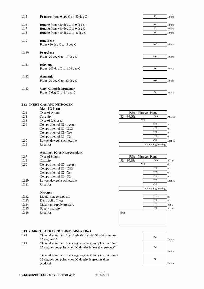
11.5 Propane from 0 deg C to -20 deg C 62 Hours
11.6 Butane from +20 deg C to 0 deg C 100 Hours
11.7 Butane from +10 deg C to 0 deg C 55 Hours
11.8 Butane from +10 deg C to -5 deg C 80 Hours
11.9 Butadiene
From +20 deg C to -5 deg C 100 Hours
11.10 Propylene
From -20 deg C to -47 deg C 144 Hours
11.11 Ethylene
From -100 deg C to -104 deg C 70 Hours
11.12 Ammonia
From -20 deg C to -33 deg C 168 Hours
11.13 Vinyl Chloride Monomer
From -5 deg C to -14 deg C 50 Hours
B12 INERT GAS AND NITROGEN
Main IG Plant
12.1 Type of system
12.2 Capacity N2 - 99,5% 1000 Nm3/hr
12.3 Type of fuel used
12.4 Composition of IG - oxygen N/A %
Composition of IG - CO2 N/A %
Composition of IG - Nox N/A %
Composition of IG - N2 N/A %
12.5 Lowest dewpoint achievable -50 Deg. C
12.6 Used for N2 purging/Inerting
Auxiliary IG or Nitrogen plant
12.7 Type of System
12.8 Capacity N2 - 99,5% 1000 m3/hr
12.9 Composition of IG - oxygen %
Composition of IG - CO2 N/A %
Composition of IG - Nox N/A %
Composition of IG - N2 N/A %
12.10 Lowest dewpoint achievable N/A Deg. C
12.11 Used for -50
N2 purging/Inerting
Nitrogen
12.12 Liquid storage capacity N/A m3
12.13 Daily boil-off loss N/A m3
12.14 Maximum supply pressure N/A Bar g
12.15 Supply capacity N/A m3/hr
12.16 Used for
B13 CARGO TANK INERTING/DE-INERTING
13.1 Time taken to inert from fresh air to under 5% O2 at minus
25 degree C?24
Hours
13.2 Time taken to inert from cargo vapour to fully inert at minus
25 degrees dewpoint when IG density is less than product? 24
Hours
Time taken to inert from cargo vapour to fully inert at minus
25 degrees dewpoint when IG density is greater than
product?
30
Hours
B14 GAS FREEING TO FRESH AIR
PSA - Nitrogen Plant
N/A
N/A
PSA - Nitrogen Plant
N/A
HHI Version12/2004 -YSL
Page 15
HHI - Gas Form-C
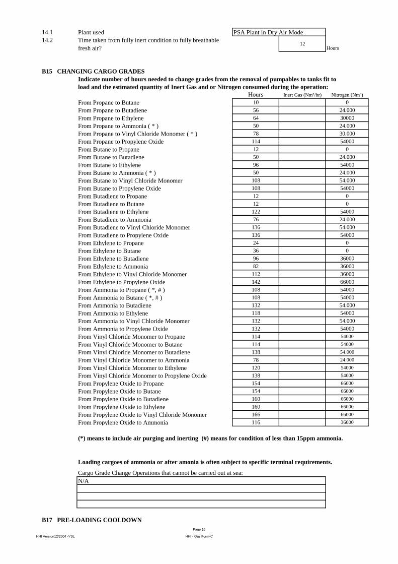
14.1 Plant used
14.2 Time taken from fully inert condition to fully breathable
fresh air?12
Hours
B15 CHANGING CARGO GRADES
Indicate number of hours needed to change grades from the removal of pumpables to tanks fit to
load and the estimated quantity of Inert Gas and or Nitrogen consumed during the operation:
Hours Inert Gas (Nm³/hr) Nitrogen (Nm³)
From Propane to Butane 10 0
From Propane to Butadiene 56 24.000
From Propane to Ethylene 64 30000
From Propane to Ammonia ( * ) 50 24.000
From Propane to Vinyl Chloride Monomer ( * ) 78 30.000
From Propane to Propylene Oxide 114 54000
From Butane to Propane 12 0
From Butane to Butadiene 50 24.000
From Butane to Ethylene 96 54000
From Butane to Ammonia ( * ) 50 24.000
From Butane to Vinyl Chloride Monomer 108 54.000
From Butane to Propylene Oxide 108 54000
From Butadiene to Propane 12 0
From Butadiene to Butane 12 0
From Butadiene to Ethylene 122 54000
From Butadiene to Ammonia 76 24.000
From Butadiene to Vinyl Chloride Monomer 136 54.000
From Butadiene to Propylene Oxide 136 54000
From Ethylene to Propane 24 0
From Ethylene to Butane 36 0
From Ethylene to Butadiene 96 36000
From Ethylene to Ammonia 82 36000
From Ethylene to Vinyl Chloride Monomer 112 36000
From Ethylene to Propylene Oxide 142 66000
From Ammonia to Propane ( *, # ) 108 54000
From Ammonia to Butane ( *, # ) 108 54000
From Ammonia to Butadiene 132 54.000
From Ammonia to Ethylene 118 54000
From Ammonia to Vinyl Chloride Monomer 132 54.000
From Ammonia to Propylene Oxide 132 54000
From Vinyl Chloride Monomer to Propane 114 54000
From Vinyl Chloride Monomer to Butane 114 54000
From Vinyl Chloride Monomer to Butadiene 138 54.000
From Vinyl Chloride Monomer to Ammonia 78 24.000
From Vinyl Chloride Monomer to Ethylene 120 54000
From Vinyl Chloride Monomer to Propylene Oxide 138 54000
From Propylene Oxide to Propane 154 66000
From Propylene Oxide to Butane 154 66000
From Propylene Oxide to Butadiene 160 66000
From Propylene Oxide to Ethylene 160 66000
From Propylene Oxide to Vinyl Chloride Monomer 166 66000
From Propylene Oxide to Ammonia 116 36000
Cargo Grade Change Operations that cannot be carried out at sea:
N/A
B17 PRE-LOADING COOLDOWN
(*) means to include air purging and inerting (#) means for condition of less than 15ppm ammonia.
PSA Plant in Dry Air Mode
Loading cargoes of ammonia or after amonia is often subject to specific terminal requirements.
HHI Version12/2004 -YSL
Page 16
HHI - Gas Form-C
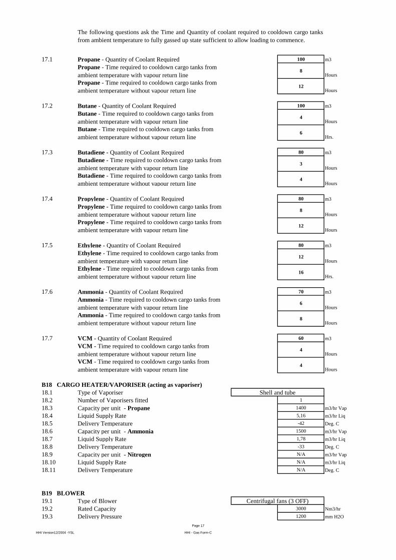
17.1 Propane - Quantity of Coolant Required 100 m3
Propane - Time required to cooldown cargo tanks from
ambient temperature with vapour return line8
Hours
Propane - Time required to cooldown cargo tanks from
ambient temperature without vapour return line12
Hours
17.2 Butane - Quantity of Coolant Required 100 m3
Butane - Time required to cooldown cargo tanks from
ambient temperature with vapour return line4
Hours
Butane - Time required to cooldown cargo tanks from
ambient temperature without vapour return line6
Hrs.
17.3 Butadiene - Quantity of Coolant Required 80 m3
Butadiene - Time required to cooldown cargo tanks from
ambient temperature with vapour return line3
Hours
Butadiene - Time required to cooldown cargo tanks from
ambient temperature without vapour return line4
Hours
17.4 Propylene - Quantity of Coolant Required 80 m3
Propylene - Time required to cooldown cargo tanks from
ambient temperature without vapour return line8
Hours
Propylene - Time required to cooldown cargo tanks from
ambient temperature with vapour return line12
Hours
17.5 Ethylene - Quantity of Coolant Required 80 m3
Ethylene - Time required to cooldown cargo tanks from
ambient temperature with vapour return line12
Hours
Ethylene - Time required to cooldown cargo tanks from
ambient temperature without vapour return line16
Hrs.
17.6 Ammonia - Quantity of Coolant Required 70 m3
Ammonia - Time required to cooldown cargo tanks from
ambient temperature with vapour return line6
Hours
Ammonia - Time required to cooldown cargo tanks from
ambient temperature without vapour return line8
Hours
17.7 VCM - Quantity of Coolant Required 60 m3
VCM - Time required to cooldown cargo tanks from
ambient temperature without vapour return line4
Hours
VCM - Time required to cooldown cargo tanks from
ambient temperature with vapour return line4
Hours
B18 CARGO HEATER/VAPORISER (acting as vaporiser)
18.1 Type of Vaporiser
18.2 Number of Vaporisers fitted 1
18.3 Capacity per unit - Propane 1400 m3/hr Vap
18.4 Liquid Supply Rate 5,16 m3/hr Liq
18.5 Delivery Temperature -42 Deg. C
18.6 Capacity per unit - Ammonia 1500 m3/hr Vap
18.7 Liquid Supply Rate 1,78 m3/hr Liq
18.8 Delivery Temperature -33 Deg. C
18.9 Capacity per unit - Nitrogen N/A m3/hr Vap
18.10 Liquid Supply Rate N/A m3/hr Liq
18.11 Delivery Temperature N/A Deg. C
B19 BLOWER
19.1 Type of Blower
19.2 Rated Capacity 3000 Nm3/hr
19.3 Delivery Pressure 1200 mm H2O
The following questions ask the Time and Quantity of coolant required to cooldown cargo tanks
from ambient temperature to fully gassed up state sufficient to allow loading to commence.
Shell and tube
Centrifugal fans (3 OFF)
HHI Version12/2004 -YSL
Page 17
HHI - Gas Form-C
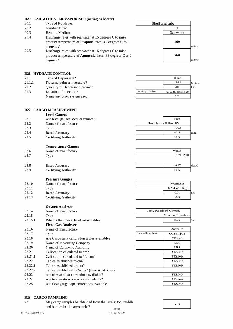
B20 CARGO HEATER/VAPORISER (acting as heater)
20.1 Type of Re-Heater
20.2 Number Fitted 1
20.3 Heating Medium Sea water
20.4 Discharge rates with sea water at 15 degrees C to raise
product temperature of Propane from -42 degrees C to 0
degrees C
400
m3/hr
20.5 Discharge rates with sea water at 15 degrees C to raise
product temperature of Ammonia from -33 degrees C to 0
degrees C
260
m3/hr
B21 HYDRATE CONTROL
21.1 Type of Depressant? Ethanol
21.1.1 Freezing point temperature? -114,1 Deg. C
21.2 Quantity of Depressant Carried? 200 Ltr.
21.3 Location of injection? Outlet cgo receiver At pump discharge
Name any other system used N/A
B22 CARGO MEASUREMENT
Level Gauges
22.1 Are level gauges local or remote? Both
22.2 Name of manufacture
22.3 Type Float
22.4 Rated Accuracy +/- 2 mm.
22.5 Certifying Authority SGS
Temperature Gauges
22.6 Name of manufacture WIKA
22.7 Type
22.8 Rated Accuracy <0,27 deg C
22.9 Certifying Authority SGS
Pressure Gauges
22.10 Name of manufacture Rosemount
22.11 Type 82234 Wessling
22.12 Rated Accuracy 0,01 bar
22.13 Certifying Authority SGS
Oxygen Analyser
22.14 Name of manufacture
22.15 Type
22.15.1 What is the lowest level measurable? 0-25 %
Fixed Gas Analyser
22.16 Name of manufacture Autronica
22.17 Type Flammable analyser OGS 3,11/16
22.18 Are Cargo tank calibration tables available? YES/NO
22.19 Name of Measuring Company SGS
22.20 Name of Certifying Authority LRS
22.21 Calibration calculated to cm? YES/NO
22.21.1 Calibration calculated to 1/2 cm? YES/NO
22.22 Tables established to cm? YES/NO
22.22.1 Tables established to mm? YES/NO
22.22.2 Tables established to "other" (state what other)
22.23 Are trim and list corrections available? YES/NO
22.24 Are temperature corrections available? YES/NO
22.25 Are float gauge tape corrections available? YES/NO
B23 CARGO SAMPLING
23.1 May cargo samples be obtained from the levels; top, middle
and bottom in all cargo tanks?YES
Henri System Holland BV
Shell and tube
TR 95 Pt100
Bernt, Dusseldorf, Germany
Crowcon, Txgard-IS+
HHI Version12/2004 -YSL
Page 18
HHI - Gas Form-C
If no, - the arrangement for sampling is limited to:
23.2 Can samples be drawn from tank vapour outlet? YES
Can samples be drawn from manifold liquid line? YES
Can samples be drawn from manifold vapour line? YES
Can samples be drawn from pump discharge line? YES
23.3 State sample connection type BALL VALVE NPT(F)
Size of sample connection 1/2" BSPP
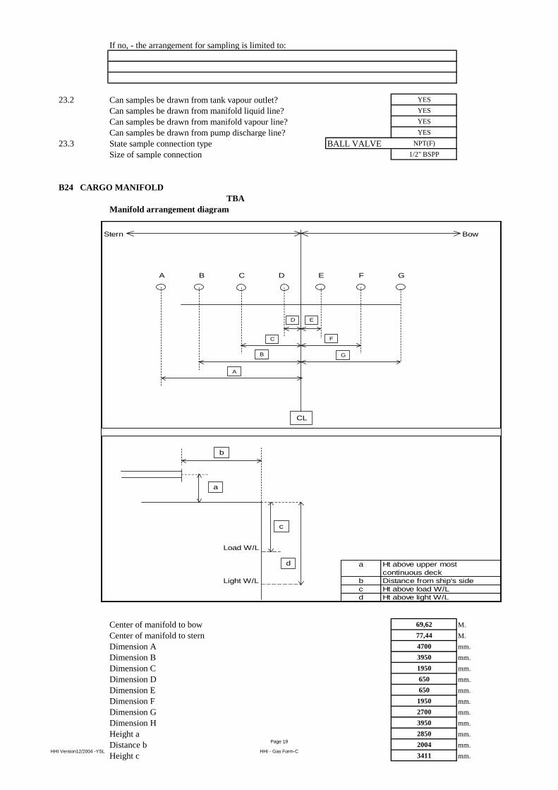
B24 CARGO MANIFOLD
TBA
Manifold arrangement diagram
Center of manifold to bow 69,62 M.
Center of manifold to stern 77,44 M.
Dimension A 4700 mm.
Dimension B 3950 mm.
Dimension C 1950 mm.
Dimension D 650 mm.
Dimension E 650 mm.
Dimension F 1950 mm.
Dimension G 2700 mm.
Dimension H 3950 mm.
Height a 2850 mm.
Distance b 2004 mm.
Height c 3411 mm.
Stern Bow
A B C D E F G
Load W/L
a Ht above upper most
continuous deck
Light W/L b Distance from ship's side
c Ht above load W/L
d Ht above light W/L
CL
a
b
c
d
A
ED
FC
GB
HHI Version12/2004 -YSL
Page 19
HHI - Gas Form-C
Height d 9125 mm.
Pipe Flange A - duty Fuel oil (D.O.)
Pipe Flange A - rating 3,3 bar
Pipe Flange A - size 100A mm.
Pipe Flange A raised or flat face Raised
Pipe Flange B - duty Fuel oil
Pipe Flange B - rating 3,3 bar
Pipe Flange B - size 150A mm.
Pipe Flange B raised or flat face Raised
Pipe Flange C - duty Liquid System II
Pipe Flange C - rating 30 bar
Pipe Flange C - size 10"
Pipe Flange C raised or flat face Raised
Pipe Flange D - duty Vapour System II
Pipe Flange D - rating 18,6 bar
Pipe Flange D - size 6"
Pipe Flange D raised or flat face Raised
Pipe Flange E - duty Vapour System I
Pipe Flange E - rating 18,6 bar
Pipe Flange E - size 4"
Pipe Flange E raised or flat face Raised face
Pipe Flange F - duty Liquid System I
Pipe Flange F - rating 30 bar
Pipe Flange F - size 8"
Pipe Flange F raised or flat face Raised face
Pipe Flange G - duty Nitrogen
Pipe Flange G - rating 6 bar
Pipe Flange G - size 3" mm.
Pipe Flange G raised or flat face Raised face
Pipe Flange H - duty Fuel oil
Pipe Flange H - rating 3,3 bar
Pipe Flange H - size 150A mm.
Pipe Flange H raised or flat face Raised face
Height above uppermost continuous deck 2850 mm.
Distance from ship side 2517 mm.
Height above load waterline 6261 mm.
Height above light waterline 11975 mm.
Manifold Arrangement Located on Top of Compressor
Distance from rail of compressor room/platform to
presentation flangesN/A
mm.
Distance from deck of compressor room/platform/try to
centre of manifoldN/A
mm.
B25 CARGO MANIFOLD REDUCERS
25.1 Number of ANSI Class 300 reducers carried onboard 14
Flange rating of ANSI Class 300 reducer 30 bar
Size of ANSI Class 300 reducer Var mm.
Length of ANSI Class 300 reducer 500 mm.
25.2 Number of ANSI Class 300 to Class 150 reducers carried
onboard14
Flange rating of ANSI Class 300 to Class 150 reducer 18,6 bar
Size of ANSI Class 300 to Class 150 reducer Var mm.
Length of ANSI Class 300 to Class 150 reducer 500 mm.
25.3 Number of ANSI Class 150 reducers carried onboard 4 (FO/DO)
Flange rating of Class 150 reducer 18,6 bar
Size of ANSI Class 150 reducer Var mm.
Length of ANSI Class 150 reducer 500 mm.
B26 CONNECTIONS TO SHORE FOR ESD AND COMMUNICATIONS SYSTEMS
26.1 Is ESD connection to shore available? YES
If yes, is the system pneumatic? NO
If yes, is the system electrical? YES
If yes, is the system fiber optic? NOHHI Version12/2004 -YSL
Page 20
HHI - Gas Form-C
26.2 What is the type of connection used?
26.3 Are ESD hoses or cables available on board? YES
If yes, length of pneumatic 0 mm.
If yes, length of electrical 30 m
If yes, length of fiber optic 0 mm.
26.4 Is there a connection available for a telephone line? NO
26.5 Are ESD connections available on both sides of vessel? YES
Are ESD Fusible plugs fitted at tank domes? YES
Are ESD Fusible plugs fitted at manifolds? YES
Is the link compatible with the SIGTTO guidelines? YES
Type of manifold valve
Closing time in seconds 28 secs
Is closing time adjustable? YES
Is Independent high level shut down system fitted(overflow
control)?YES
If yes, does the independent high level shutdown system also
switch off running cargo pumps?YES
Shut down level % 98 %
B27 MANIFOLD DERRICK/CRANE
27.1 Is manifold derrick provided NO
27.2 Is manifold crane provided YES
27.3 Is lifting equipment same for port and starboard? Yes
If no, then stipulate details
27.4 State SWL at maximum outreach 5 Tonnes
27.4.1 Maximum outreach of lifting equipment 7 Metres
B28 STORES DERRICK/CRANE
28.1 State location
SWL 4 Tonnes
B29 SISTER VESSEL(S)
29.1 Name of vessel
Othoni
Kithnos
Astipalea
Accommodation AFT STB'D sides
Actuated Butterfly
-
Pendant
HHI Version12/2004 -YSL
Page 21
HHI - Gas Form-C