Embed Size (px)
Citation preview
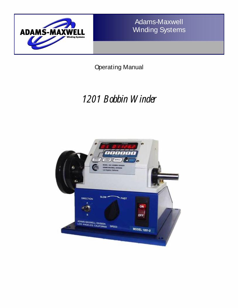
1201 Bobbin Winder
Operating Manual
Adams-Maxwell
Winding Systems
1201 Bobbin Winder
Page 2
Adams-Maxwell
4740 Calle Carga
Camarillo, CA 93012
Phone: (323) 936-8028
Fax: (888) 936-8042
Web: www.AdamsMaxwell.com
Email: [email protected]
Adams-Maxwell Winding Systems
Page 3
Table of Contents
Section 1: Introduction. . . . . . . . . . . . . . . . . . . . . . . . . . . . . . . . . . . . . 4
Section 2: Operation and Programming. . . . . . . . . . . . . . . . . . . . . . . 7
Section 3: Maintenance. . . . . . . . . . . . . . . . . . . . . . . . . . . . . . . . . . . . . 19
Section 4: Accessories. . . . . . . . . . . . . . . . . . . . . . . . . . . . . . . . . . . . . . 21
Adams-Maxwell Winding Systems

Page 4
Section 1 - Introduction
Congratulations on your purchase of the Adams-Maxwell Series Bobbin Winder. There are four different
models to choose from depending on your operational requirements for speed and torque. The 1201 Se-
ries Bobbin Winder combines a precision counterhead assembly and motor-controlled drive to give com-
pact and efficient machine. It is well suited for medium to fine wire winding applications. Comprised of
an electronic counter, DC Motor and a foot rheostat pedal to control the start and speed of the winder.
Each machine is equipped with dynamic breaking for precise winding control, multi-range electronic foot
speed control, bright LED readout to nearest 1/10 of a turn. The arbor rotation can be programmed either
as top-coming or top-going with either a negative or positive count.
Limited Warranty Adams-Maxwell warrants this equipment for ONE full year from the date of Invoice against defects in
workmanship and components except: Breakage of parts and/or Damage caused by misuse or mishan-
dling. Misuse includes operation of the equipment outside of its intended range or evidence of tampering
(i.e. opening the machine, attempted repairs). Any evidence of tampering or attempted repairs will void
the warranty.
Adams-Maxwell reserves the right to make repairs or replacements either at its plant or at the customer's
location at Adams-Maxwell option. Equipment is to be returned to Adams-Maxwell at owner's expense
and is subject to inspection for verification of warranty repairs. If repairs are covered by this warranty, the
equipment will be repaired at Adams-Maxwell's expense. All warranty repairs are to be made by Adams-
Maxwell. This warranty is in lieu of any and all other warranties, including but not limited to warranties of
marketability and fitness for a particular purpose. In no event shall Adams-Maxwell be liable for indirect
or consequential damages or special expense of any kind as a result of breach of express warranty or as
a result of the use or misuse of the equipment.
The MOSS-MAGNUSON warranty act of 1975 provides certain specific rights to the purchaser. This war-
ranty is termed a LIMITED WARRANTY as defined in that act but, as such, in no way compromises the high
quality of performance, workmanship and customer service of Adams-Maxwell.
Adams-Maxwell Winding Systems
Adams-Maxwell Winding Systems Page 5
Unpacking and Inspection Upon receipt , the machine should be unpacked and checked to see that there is no apparent shipping
damages and that all attachments and accessories ordered are included. The initial responsibility for
any damage or loss resulting from shipping lies with the cosignee. Please refer to the notice accompany-
ing the machine for details of this responsibility.
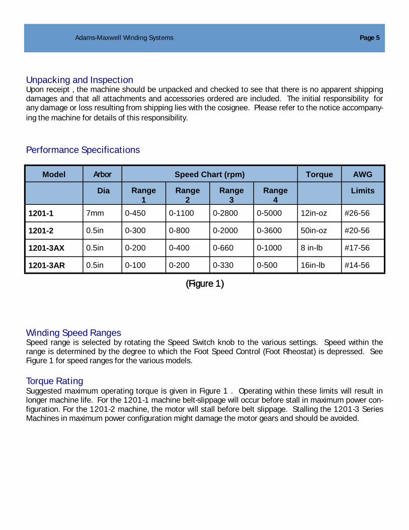
Performance Specifications
Winding Speed Ranges Speed range is selected by rotating the Speed Switch knob to the various settings. Speed within the
range is determined by the degree to which the Foot Speed Control (Foot Rheostat) is depressed. See
Figure 1 for speed ranges for the various models.
Torque Rating Suggested maximum operating torque is given in Figure 1 . Operating within these limits will result in
longer machine life. For the 1201-1 machine belt-slippage will occur before stall in maximum power con-
figuration. For the 1201-2 machine, the motor will stall before belt slippage. Stalling the 1201-3 Series
Machines in maximum power configuration might damage the motor gears and should be avoided.
Model Arbor Speed Chart (rpm) Torque AWG
Dia Range
1
Range
2
Range
3
Range
4
Limits
1201-1 7mm 0-450 0-1100 0-2800 0-5000 12in-oz #26-56
1201-2 0.5in 0-300 0-800 0-2000 0-3600 50in-oz #20-56
1201-3AX 0.5in 0-200 0-400 0-660 0-1000 8 in-lb #17-56
1201-3AR 0.5in 0-100 0-200 0-330 0-500 16in-lb #14-56
(Figure 1)

Page 6
Winding Direction The machine is initially programmed to a ―Top Going‖ rotation with a corresponding positive count when
the machine is powered on. The machine can be reprogrammed to a ―Top Coming‖ rotation with positive
count. The actual rotation of direction of the arbor is controlled by the Direction Switch.
Counter The range of the electronic counter is from 0 to 99,999.9. Program groups store multiple programmable
winding sequences.
Overrun Overrun from the preset at maximum speed of 5000 rpm is approximately 4 turns. This is very consistent
and may be mostly compensated by setting the preset low. At lower speeds overrun is proportional to
speed.
Electrical and Physical Specifications Motor type: DC motor, triac type motor speed circuitry
Braking: Dynamic
Speed Control: Multi-range electronic foot control
Voltage Requirements: 117 Volts, 48-63 Hz
Power Requirements: Approximately 100 VA
Weight: 26 lbs.
Size: 15‖ Wide, 28‖ Deep, 13‖ High
Cosmetic: Blue Polyester Finish
Arbor Diameter: 7mm (.27 in) for 1201-0 and 1201-1
Arbor Diameter: 0.5in for 1201-2 and 1203 Series
EPROM Version: GNERIC_0.HEX 6/10/93
The winder is adjusted at the facility for 60 Hertz operations. To operate the winder at other than 60
Hertz (48-63) contact Customer Service.
Adams-Maxwell Winding Systems

Section 2 - Operation & Programming
Basic Winder Configuration The basic winder as supplied includes:
Bobbin Winder
Foot Speed Control (foot rheostat)
Power Cord
Spare set of motor brushes
Spare belt
Machine Setup The machine must be set up on a sturdy surface and adequately secured. Unpack all components, and
assemble as follows:
1 Connect the Foot Speed Control (Foot Rheostat) male plug to the corresponding female recep-
tacle on the left of the machine. Rotate plug clockwise to lock in place.
2 Connect the power cord female plug to the corresponding male receptacle on the left of the ma-
chine and connect the power cord male plug to a power source.
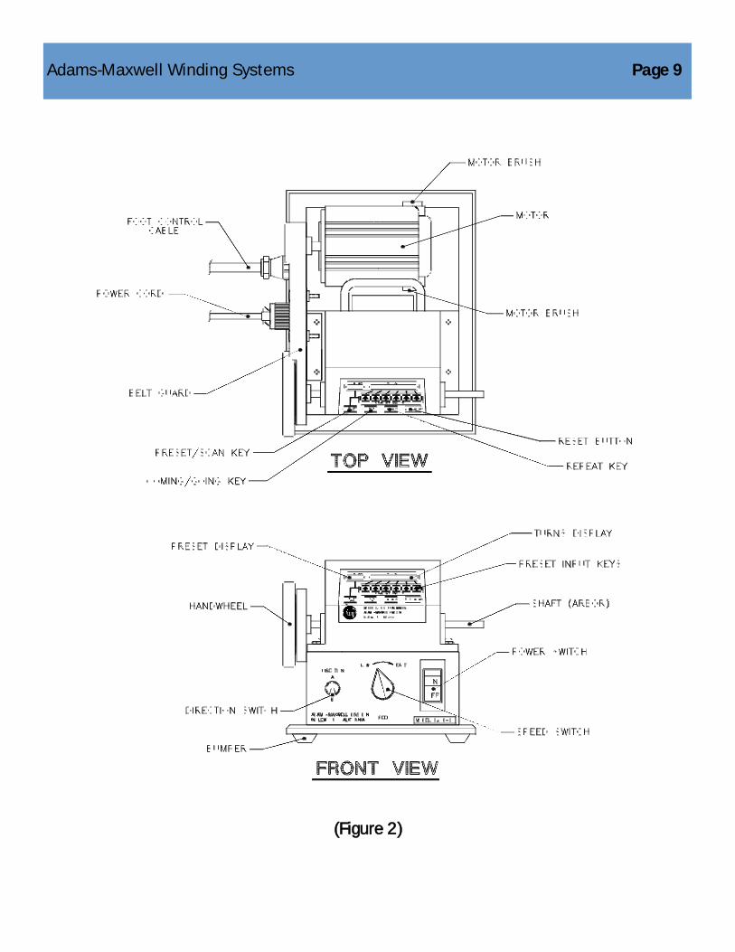
Machine Operation (Refer to Figure 2, pg. 9)
1. Toggle the Power Switch to ―ON‖
2. Set the directional switch to ―A‖ (Forward)
3. Set the Speed Range switch to the desired speed. It is recommended that first time users select
―SLOW‖ while familiarizing themselves with the machine.
4. Secure a bobbin or winding form on the mandrel and secure the winding wire
5. Reset the counter to zero by pressing the Reset button
6. Depress the foot control to begin winding and to control speed during winding. The turns window
displays the current turns count.
Adams-Maxwell Winding Systems Page 7

Page 8
7. The machine will automatically stop upon reaching the first preset. If necessary adjust the turns with
the hand wheel. If multiple presets are programmed, then the next sequential preset will begun once
the foot control is depressed. When the last winding sequence is completed
secure the winding wire and remove the bobbin or winding form from the
mandrel.
Multiple Presets In operation, a program with multiple presets would operate as follows: When the first preset is hit the
winder automatically stops. When the foot pedal is pressed again, the winder will start the next preset.
This sequence continues until all programmed presets are cycled through. To begin the winding se-
quence from the first preset, press the Reset button.
Operational Notes The machine will overrun the preset at higher speeds. Simple experimentation will demonstrate the allow-
ance that is needed to accommodate the overrun (e.g. for 200 turns at high speed, set the preset to
―196‖ turns).
The hand wheel is used to give precise control at the start and finish of the winding when the machine is
stopped or turning very slowly. Do not use the hand wheel to stall the machine. Also, holding or touching
the hand wheel when it is rotating can cause rapid heat build up which can cause a burn to the operator‘s
hand and places excess strain on the motor.
Do not reverse the direction of the machine while running. This places electrical and mechanical tran-
sient loads on the machine and can shorten the life of the components.
Adams-Maxwell Winding Systems
Adams-Maxwell Winding Systems Page 9
(Figure 2)
Winding Sequences (Programs) A winding sequence or program is made up of 1 to 99 program steps (presets). Differing winding se-
quences can be programmed, stored, and later recalled from memory to perform specific winding se-
quence. The programs are stored in nonvolatile memory, which means the programs will remain in mem-
ory even when the machine is turned off. Programs can be added or changed at any time. Each program
is given a unique number, e.g. 01, 02, 03 which is selected in the ―Function Mode‖ using Function Code
4 (see both the Program Groups Section and Function Mode section).
As mentioned above, a winding program is made up of program steps, usually referred to as presets.
Each preset is defined by three items:
1. Number of Turns
2. Absolute or Additive Count
3. Preset End or Preset Continue
Number of Turns: Each preset has a defined number of turns which establishes the completion point of
that winding. For example, if 85 turns are required then the preset is programmed to 85 turns. In opera-
tion, the winder would wind 85 turns and then automatically stop.
Preset Continue (PC) and Preset End (PE): Since the winding program can have multiple presets we need
to establish which preset will be last in a sequence by marking it with a Preset End (PE). All other presets
would be market as Preset Continue (PC). For example, a sequence of 3 windings will have presets one
and two marked as ―PC‖ and preset three marked as ―PE.‖ In operation, when the winder encounters a
preset with a ―PE‖ it will automatically end the winding program. Pressing the Reset button is required to
reset the counter back to zero and to ready the winder to again start the winding sequence. Note: All pre-
sets must be marked as either ―PE‖ or ―PC.‖
Absolute ‗vs‘ Additive: In addition to each preset being defined with the number of turns and as either PC
or PE, it must also be labeled as either Absolute (ABS) or Additive (ADD). When the preset is marked as
Absolute the counter starts from zero. When marked as Additive the counter continues from the previous
preset.
This is best explained with the following example. The transformer‘s winding sequence has 80 turns on
the primary and 240 turns on the secondary with a tap at 180 turns. The winding sequence would be as
follows:
Preset 1 80 Turns PC ABS
Preset 2 180 Turns PC ABS
Preset 3 240 Turns PE ADD
Page 10 Adams-Maxwell Winding Systems

Adams-Maxwell Winding Systems Page 11
As shown in the example the winder would start at zero and stop at 80 turns. When the pedal is pressed,
the winder would then proceed to preset 2 by again starting at zero and stopping at 180 turns. Now for
preset 3, since it is marked with the ―ADD‖ it would not start from zero but would continue from 180 turns
until 240 turns are reached. Since preset 3 is designated as PE, the winder automatically ends the se-
quence and thus would reset back to preset 1 when the Reset button is pressed (All presets must be
marked as either ADD or ABS. Preset 1 must always be marked as ABS. When marking a preset as ADD
it must be a larger number than the previous preset).
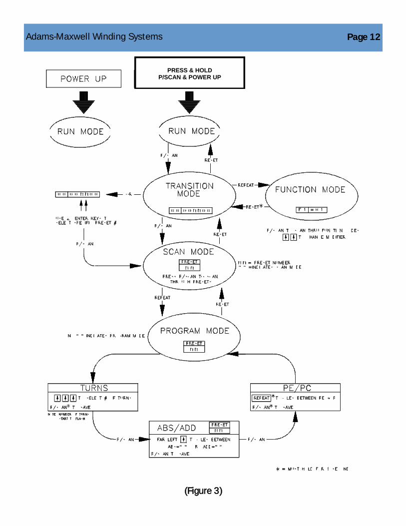
Operational Modes There are five operational modes for the 1201 Bobbin Winder. Moving between modes is best described
by reviewing Figure 3. Each of these operation modes have a specific purpose of which are described as
follows:
Program Mode is where program sequences are created or edited. A program sequence is made up of
one or more program steps. A program step consist of defining a preset with its number of turns, PC or
PE, and ABS or ADD.
Run Mode is where the actual winding takes place. When the bobbin winder is turned on ―Run Mode‖ is
the default, which means the winder is ready to wind the programmed sequence.
Transition Mode is the mode when switching between ―Run Mode,‖ ―Function Mode,‖ or ―Scan Mode.‖ In
―Transition Mode‖ the display will indicate all zeros, 00 000000.
Scan Mode allows you to serially scan through all presets to make program changes and/or to verify data
has been entered correctly. In ―Scan Mode‖ the display indicates ―x.x.‖, where xx represents the preset
number and the ―.‖ represents ―Scan Mode.‖ For example, ―1.6‖ means Preset 16 and the ―.‖ indicates
―Scan Mode.‖ Note that you cannot scan past a preset that has been set as ―PE.‖
Function Mode contains special functions such as defining your program group, selection of your pro-
gram sequence and shaft rotation. See additional information in the Function Mode Section (page 15).
Keypad Lockout When powered on the keypad is locked out except for: the Reset Button, the Repeat Key and the Coming/
Going key. Press and hold the Preset Scan Key while the machine is powered on to enable the keypad.
This allows the winder to be programmed (see page 13).
Page 12
(Figure 3)
PRESS & HOLD
P/SCAN & POWER UP
Adams-Maxwell Winding Systems

Programming Procedure (refer to figure 3 and figure 4)
Step 1: To program the bobbin winder press down and hold the Preset
Scan key and then turn on the Power Switch. This will take
you into ―Run Mode.‖
Step 2: Press the Preset Scan key to take you into ―Transition Mode.‖
Note the display is ―00 00000‖ to indicate you are in Transition
Mode.
Step 3: Press the Preset Scan key to enter the ―Scan Mode.‖ You can
now scan through all the presets by repetitively pressing the Pre
Set Scan key. Note that the Preset Display has a ―.‖ which
Indicates you are in ―Scan Mode.‖
Step 4: To program a particular preset you must press the Repeat
key. You are now in the ―Program Mode‖ and can define the
selected preset. Note that the absence of the decimal point ―.‖
in the Preset Display indicates that you are in ―Program Mode.‖
Turns: Press the Preset Input keys to select the number of turns. Press
the Preset Scan key to save. Note that the display starts to
flash when you press the Preset Input keys.
ABS/ADD: Press the far left Preset Input key to mark as either Absolute or
Additive. A decimal point ―.‖ will appear in the preset display to
indicate Absolute is selected. The absence of a decimal point
indicates that Additive is selected. Once established, press and
hold the Preset Scan key to save.
PE/PC Press and hold the Repeat key for 2 seconds to select between
PE or PC. Once established, press and hold the Preset Scan key
for 2 seconds to save.
Step 5: To return to the ―Scan Mode‖ press the Reset key
Step 6: To return to the ―Transition Mode‖ press the Reset key
Step 7: To return to the ―Run Mode‖ press the Reset key
Multiple presets can be defined by repeating Steps 3 through 5.
Adams-Maxwell Winding Systems Page 13

Program Groups The 1201 Series Bobbin Winder can be user configured to any one of five program groups. By default
the factory settings is Program Group 1. This provides the ability to program one winding sequence with
a maximum of 99 presets. Either Program Group 1, 2, 3, 4 or 5 must be selected. Each program group
has a specific maximum number of winding sequences (programs) associated with it and the maximum
number of preset (program steps) for each of these winding sequences. The program groups are as
follows:
The flexibility allows the user to best configure the winder to their application. If a user has winding se-
quences that requires up to 40 program steps then Program Group 3 should be selected. On the other
hand if the winding sequences are never greater than 10 program steps then Program Group 5 should
be selected. Program group 5 would allow you to program/access up to 16 different winding sequences
(programs), each with up to 10 program. steps (presets). A preset consists of defining the number of
turns, PC or PE, and ABS or ADD.
Page 14
Program
Group
# of Winding
Sequences
# of Pre Sets
per Winding
Sequence
1 1 99
2 2 80
3 4 40
4 8 20
5 16 10
Adams-Maxwell Winding Systems
(Figure 4)
Adams-Maxwell Winding Systems

The Bobbin Winder must be set to one of these five program groups. Please note that once a program
group is selected and winding sequence entered in, changing the Program Group will lose the old winding
program.
All programs are stored in non-volatile memory which means that the programs are always stored even
when the winder is turned off. The programs can be reprogrammed as often as needed. Programs can
also be saved on a removable memory module (see Option P, page 22).
Selection of the Program Group is done through the Function Mode F3 (See Function Mode Section)
Accessing a particular winding sequence to either perform a winding or to program a winding sequence is
done through the Function Mode F4 (See Function Mode Section).
Function Mode Function Mode is used to specify bobbin winder operation parameters. Entering the function Mode is
done by pressing the Repeat key while in the ―Transition Mode.‖ The display will show:
F1 = nn (where nn is referred to as a modifier and can be changed
depending upon the specific requirement—explained on
page 16)
The Modifier can be changed by pressing and holding the Preset Input keys directly below the Modifier.
Once the change is made you can either save it by pressing and holding the Preset Scan key to access
the next Function Code, or by pressing and holding the Reset key to return to the ―Transition Mode.‖
Pressing the Preset Scan key would display:
F2 = nn
You can access all the Function Codes by scanning through with Preset Scan key. At any time you can
return to the ―Transition Mode‖ by pressing and holding the Reset key.
Adams-Maxwell Winding Systems Page 15

Page 16
Function Codes and Modifiers:
The function Codes and Modifiers are describe as follows:
Function Code 01
Modifier
01
02
Description
All programming is entered from the keypad of the Winder
Inactive
Function Code 02
Modifier
01
02
Description
When the direction of the Shaft is Top Going — Counter will be
positive counting
When the direction of the shaft is Top Coming– Counter will be
positive counting
Function Code 03
Modifier
01
02
03
04
05
Description
Configures the Bobbin Winder for 1 winding program with up to
99 presets
Configures the Bobbin Winder for 2 winding programs with each
program having up to 80 presets
Configures the Bobbin Winder for 4 winding programs with each
program having up to 40 presets
Configures the Bobbin Winder for 8 winding programs with each
program having up to 20 presets
Configures the Bobbin Winder for 16 winding programs with
each program having up to 10 presets
Adams-Maxwell Winding Systems

Adams-Maxwell Winding Systems Page 17
Function Code 04
Modifier = nn
Description Selects the specific program number to either run a winding sequence or to program
a winding sequence. The nn represents this program number within the selected Program Group. For
example, if Program Group 04 is selected (F3=04), then the modifier can be set from 01 to 08 to select
any one of the eight available programs. If on the other hand Program Group 05 has been selected
(F3=05), then the modifier can be set from 01 to 016 to select any one of the sixteen available programs
Function Codes 05, 06, & 07 are not used and must be set as follows:
F5 = 01
F6 = 01
F7 = 00
To gain direct access to the ―Function Mode‖ turn on the winder while at the same time pressing down on
the Preset/Scan and the Coming/Going key. To return to ―Run Mode‖ press and hold the Reset Button
for three seconds.
Random Preset Access Program Mode: When programming or editing a winding sequence you may like to go directly to a specific
preset without having to scan through all the previous presets. This is done by accessing the preset di-
rectly as follows: While in the ―Transition Mode‖ enter the desired preset by pressing the two center Pre-
set Input keys. Once the desired preset is entered, press the Preset Scan key. The entered preset will
now appear in the preset window with the corresponding turns count in the turns window. Since the
winder is now in the ―Scan Mode‖ the Repeat key must be pressed to enter into the ―Program Mode.‖
Changes can now be made to the preset as described in the Programming Sequence Section (see page
13).
Run Mode: To access any preset while in the ―Run Mode‖ and operate the winder using that preset.
Press the Preset Scan key to activate the ―Transition Mode,‖ and then enter the desired preset by press-
ing the two center Preset Input keys. Now press the Reset button and the winder will be in the ―Run
Mode‖ at the selected preset. The winder can now be operated using that preset.
Repeat Key When the winder is in ―Run Mode,‖ the Reset button will reset the winder back to preset 01 (a.k.a. Hard
Reset). To reset the winder to the current preset (a.k.a. Soft Reset), press the repeat key.
Top Going/ Top Coming The machine is initially programmed to a ―TOP GOING‖ rotation with a corresponding positive count when
the machine is powered on. The machine can be re-programmed to a ―TOP COMING‖ rotation with a posi-
tive count by changing Function Code F2 to the ―02‖ modifier. Once the machine is programmed ―TOP
COMING‖ or ―TOP GOING‖ it will stay that way even if the winder is powered off. The machine can be tem-
porarily re-programmed to ―TOP GOING‖ or ―TOP COMING‖ at any time by pressing the Coming/Going key
when the winder is in the ―Run Mode‖ as follows:

Page 18
Display Nomenclature : CG = G (Top Going with Positive Count)
CG = C (Top Coming with Positive Count)
When the machine is powered off and back on the winder will divert back to the direction mode estab-
lished by Function Code F2.
Note: This feature does not change the direction of the arbor, only the positive direction of the Count. The di-
rection switch must be switched in order to change the shaft rotation direction.
Adams-Maxwell Winding Systems

Adams-Maxwell Winding Systems Page 19
The winder has been designed to minimize maintenance requirements. With proper use and mainte-
nance, your machine should operate trouble free for many years. The following maintenance is sug-
gested:
GEAR BOX
The 1201-3 Series Motor should occasionally be checked for the oil level in the motor gear box. To check
oil, remove the red plastic plug and insert a clean stick into the motor gear box. Measure the oil level.
The oil should be 1‖ deep. Add industrial type oil as required.
MOTOR
The motor brushes should be checked for wear approximately every 1000 hours of use and replaced
when worn.
Remove the screw caps from the two brush casings. Remove brushes. If the brushes are worn to less
than 3/8‖, replace them. To replace them, insert in brush casing, rotating to proper orientation. Be sure
springs are square. For Bodine motors on all –3 models only, detach the springs from the old brushes
and attach them to the new brushes. For all other models, the new brushes have new springs.
BELT
Periodical inspection of the drive belt should be made. Belt should be replaced if cracked, frayed, or
loose.
To replace the belt, remove the belt guard by removing the two screws on the left side of the machine.
Gently work the belt off the front gear by easing the belt toward the machine, and turning the hand wheel.
Then remove the belt from the rear gear. Lift the belt off over the hand wheel. To install the new belt, slip
the belt over the hand wheel. Then fit the belt over the rear gear. Work the belt onto the front gear by
easing it onto the gear and turning the hand wheel until the belt is properly seated on the front gear. Re-
place the belt guard and the two screws. Machine must not be operates without the belt guard securely
attached.
ARBOR
Every three months, depending on amount of use, the bushing and the roller bearing on the arbor should
be lubricated with a drop of light machine oil
CORDS
Periodic inspection of all cords should be made. To prevent the risk of electrical shock replace damaged,
worn or frayed cords immediately. Do not use a cord that has been damaged in any way.
Section 3 - Maintenance

Page 20
Possible Problem Possible Solutions
No Power
Resetting
Motor brushes worn
Check all power cords, ensure that the power switch is in the
on position, and check your power source
Press the Reset button, resetting the count to ―00000.‖ Be
sure the preset is not set to ―00000.‖
Replace the motor brushes
FOOT SPEED CONTROL
To greatly extend the life of the Foot Speed Control, clean every six months by opening the case and
blowing out any accumulated dust
OVERHAUL
It is recommended that the machine be returned to the factory for an overhaul at about 4000 hours of
service (two years of daily use). Service include:
1. reconditioning the counter
2. replacing the motor bearings
3. replacing the belt
4. checking all other components and replacing as needed
Trouble Shooting The winder is manufactured in such a way that operating malfunctions will be rare. The following is of-
fered, however, to aid in the location of a inoperative condition:
Adams-Maxwell Winding Systems

Adams-Maxwell Winding Systems Page 21
Section 4 - Accessories
Mounting Baseplate
1/2‖ thick aluminum mounting base used to mount the 1201
Bobbin Winder, 1230 Tailstock and 1250 Traverse on a
common platform. Measures 33‖ in length by 12‖ in depth.
Chuck Adapter
Standard Jacobs Chuck which mounts on the arbor as a quick
method of holding mandrels. The chuck is secured to the
arbor with two set screws.
Auto Controller
Replaces the foot rheostat pedal of the bobbin winder with
an adjustable speed control dial to provide a constant speed.
The deceleration rate can be controlled by adjusting the
variable brake dial.
Tail Stock
The tailstock is used when additional support is required
during the winding operation. Comes with a live center, one
stroke action and mounts on the 1217 baseplate. Made of
sturdy cast aluminum.
1250 Traverse
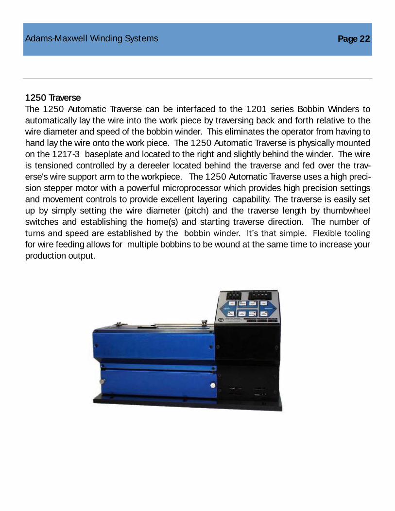
The 1250 Automatic Traverse can be interfaced to the 1201 series Bobbin Winders to
automatically lay the wire into the work piece by traversing back and forth relative to the
wire diameter and speed of the bobbin winder. This eliminates the operator from having to
hand lay the wire onto the work piece. The 1250 Automatic Traverse is physically mounted
on the 1217-3 baseplate and located to the right and slightly behind the winder. The wire
is tensioned controlled by a dereeler located behind the traverse and fed over the trav-
erse's wire support arm to the workpiece. The 1250 Automatic Traverse uses a high preci-
sion stepper motor with a powerful microprocessor which provides high precision settings
and movement controls to provide excellent layering capability. The traverse is easily set
up by simply setting the wire diameter (pitch) and the traverse length by thumbwheel
switches and establishing the home(s) and starting traverse direction. The number of
turns and speed are established by the bobbin winder. It‘s that simple. Flexible tooling
for wire feeding allows for multiple bobbins to be wound at the same time to increase your
production output.
Page 22 Adams-Maxwell Winding Systems

Page 23
Option P Memory Module
This memory module plugs into the back of the bobbin
winder where a winding program can be stored, removed
and then recalled at a future date.
Note: Bobbin winder must have Option P.
.
Mandrels
Custom mandrels designed and built for your company’s specific winding needs.
Adams-Maxwell Winding Systems

Adams-Maxwell
4740 Calle Carga
Camarillo, CA 93012
Phone: (323) 936-8042
Fax: (888) 936-8042
Web: www.AdamsMaxwell.com
Email: [email protected]