Embed Size (px)
Citation preview

Magnetic Circuits
12.1 INTRODUCTION
Magnetic and electromagnetic effects play an important role in the design of a wide variety ofelectrical/electronic systems in use today. Motors, generators, transformers, loudspeakers, re-lays, medical equipment and movements of all kinds depend on magnetic effects to functionproperly. The response and characteristics of each have an impact on the current and voltagelevels of the system, the efficiency of the design, the resulting size, and many other importantconsiderations.
Fortunately, there is a great deal of similarity between the analyses of electric circuits andmagnetic circuits. The magnetic flux of magnetic circuits has properties very similar to the cur-rent of electric circuits. As shown in Fig. 11.15, it has a direction and a closed path. The mag-nitude of the established flux is a direct function of the applied magnetomotive force resultingin a duality with electric circuits where the resulting current is a function of the magnitude ofthe applied voltage. The flux established is also inversely related to the structural oppositionof the magnetic path in the same way the current in a network is inversely related to the resis-tance of the network. All of these similarities are used throughout the analysis to clarify theapproach.
One of the difficulties associated with studying magnetic circuits is that three different sys-tems of units are commonly used in the industry. The manufacturer, application, and type ofcomponent all have an impact on which system is used. To the extent practical, the SI systemis applied throughout the chapter. References to the CGS and English systems require the useof Appendix F.
12.2 MAGNETIC FIELD
The magnetic field distribution around a permanent magnet or electromagnet was covered indetail in Chapter 11. Recall that flux lines strive to be as short as possible and take the pathwith the highest permeability. The flux density is defined by Eq. 12.1 (Eq. 11.1 repeated herefor convenience).
B �£
A
• Become aware of the similarities between the
analysis of magnetic circuits and electric circuits.
• Develop a clear understanding of the important
parameters of a magnetic circuit and how to find
each quantity for a variety of magnetic circuit
configurations.
• Begin to appreciate why a clear understanding of
magnetic circuit parameters is an important
component in the design of electrical/electronic
systems.
12Objectives
12Magnetic Circuits
B � Wb/m2 � teslas (T)� � webers (Wb) (12.1)A � m2
The “pressure” on the system to establish magnetic lines of force is determined by the ap-plied magnetomotive force which is directly related to the number of turns and current of the
boy30444_ch12.qxd 3/22/06 1:12 PM Page 513

514 ⏐⏐⏐ MAGNETIC CIRCUITS
magnetizing coil as appearing in Eq. 12.2 (Eq. 11.3 repeated here forconvenience).
� � ampere-turns (At)N � turns (t) (12.2)I � amperes (A)
The level of magnetic flux established in a ferromagnetic core is a di-rection function of the permeability of the material. Ferromagnetic ma-terials have a very high level of permeability while non-magneticmaterials such as air and wood have very low levels. The ratio of the per-meability of the material to that of air is called the relative permeabilityand is defined by Eq. 12.3 (Eq. 11.5 repeated here for convenience).
mo � 4p � 10�7Wb/A · m (12.3)
As mentioned in Chapter 11, the values of mr are not provided in atable format because the value is determined by the other quantities of themagnetic circuit. Change the magnetomotive force, and the relative per-meability changes.
12.3 RELUCTANCE
The resistance of a material to the flow of charge (current) is determinedfor electric circuits by the equation
(ohms, �)
The reluctance of a material to the setting up of magnetic flux linesin the material is determined by the following equation:
(rels, or At/Wb) (12.4)
where � is the reluctance, l is the length of the magnetic path, and A isthe cross-sectional area. The t in the units At/Wb is the number of turnsof the applied winding. More is said about ampere-turns (At) in the nextsection. Note that the resistance and reluctance are inversely proportionalto the area, indicating that an increase in area results in a reduction ineach and an increase in the desired result: current and flux. For an in-crease in length, the opposite is true, and the desired effect is reduced.The reluctance, however, is inversely proportional to the permeability,while the resistance is directly proportional to the resistivity. The largerthe m or the smaller the r, the smaller the reluctance and resistance, re-spectively. Obviously, therefore, materials with high permeability, suchas the ferromagnetics, have very small reluctances and result in an in-creased measure of flux through the core. There is no widely acceptedunit for reluctance, although the rel and the At/Wb are usually applied.
12.4 OHM’S LAW FOR MAGNETIC CIRCUITS
Recall the equation
Effect �cause
opposition
r �l
mA
R � rl
A
mr �m
mo
f � NI
boy30444_ch12.qxd 4/11/06 7:34 AM Page 514
MAGNETIZING FORCE ⏐⏐⏐ 515
appearing in Chapter 4 to introduce Ohm’s law for electric circuits. Formagnetic circuits, the effect desired is the flux �. The cause is the mag-netomotive force (mmf) �, which is the external force (or “pressure”)required to set up the magnetic flux lines within the magnetic material.The opposition to the setting up of the flux � is the reluctance �.
Substituting, we have
(12.5)
Since � � NI, Eq. 12.5 clearly reveals that an increase in the number ofturns or the current through the wire in Fig. 12.1 results in an increased“pressure” on the system to establish the flux lines through the core.
Although there is a great deal of similarity between electric and mag-netic circuits, you must understand that the flux � is not a “flow” vari-able such as current in an electric circuit. Magnetic flux is established inthe core through the alteration of the atomic structure of the core due toexternal pressure and is not a measure of the flow of some charged parti-cles through the core.
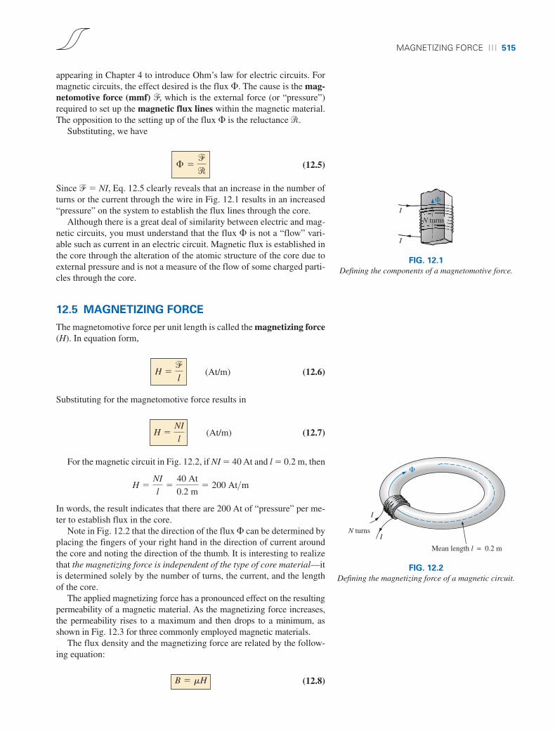
12.5 MAGNETIZING FORCE
The magnetomotive force per unit length is called the magnetizing force(H). In equation form,
(At/m) (12.6)
Substituting for the magnetomotive force results in
(At/m) (12.7)
For the magnetic circuit in Fig. 12.2, if NI � 40 At and l � 0.2 m, then
In words, the result indicates that there are 200 At of “pressure” per me-ter to establish flux in the core.
Note in Fig. 12.2 that the direction of the flux � can be determined byplacing the fingers of your right hand in the direction of current aroundthe core and noting the direction of the thumb. It is interesting to realizethat the magnetizing force is independent of the type of core material—itis determined solely by the number of turns, the current, and the lengthof the core.
The applied magnetizing force has a pronounced effect on the resultingpermeability of a magnetic material. As the magnetizing force increases,the permeability rises to a maximum and then drops to a minimum, asshown in Fig. 12.3 for three commonly employed magnetic materials.
The flux density and the magnetizing force are related by the follow-ing equation:
(12.8)B � mH
H �NI
l�
40 At
0.2 m� 200 At>m
H �NI
l
H �f
l
£ �f
r
I
I
�
N turns
FIG. 12.1
Defining the components of a magnetomotive force.
Mean length l = 0.2 m
I
IN turns
�
FIG. 12.2
Defining the magnetizing force of a magnetic circuit.
boy30444_ch12.qxd 3/22/06 1:12 PM Page 515

516 ⏐⏐⏐ MAGNETIC CIRCUITS
10
9
8
7
6
5
4
3
2
1
0
μ (permeability) × 10–3μ
300 600 900 1200 1500 1800 2100 2400 2700 3000 3300 3600 3900 4200 4500 H (At/m)
Cast steel
Cast ironSheet steel
FIG. 12.3
Variation of µ with the magnetizing force.
This equation indicates that for a particular magnetizing force, the greaterthe permeability, the greater the induced flux density.
Since henries (H) and the magnetizing force (H) use the same capitalletter, it must be pointed out that all units of measurement in the text, suchas henries, use roman letters, such as H, whereas variables such as themagnetizing force use italic letters, such as H.
12.6 HYSTERESIS
A curve of the flux density B versus the magnetizing force H of a materialis of particular importance to the engineer. Curves of this type can usuallybe found in manuals, descriptive pamphlets, and brochures published bymanufacturers of magnetic materials. A typical B-H curve for a ferromag-netic material such as steel can be derived using the setup in Fig. 12.4.
The core is initially unmagnetized, and the current I � 0. If the cur-rent I is increased to some value above zero, the magnetizing force H in-creases to a value determined by
The flux � and the flux density B (B � �/A) also increase with the cur-rent I (or H). If the material has no residual magnetism, and the magnet-izing force H is increased from zero to some value Ha, the B-H curvefollows the path shown in Fig. 12.5 between o and a. If the magnetizingforce H is increased until saturation (Hs) occurs, the curve continues asshown in the figure to point b. When saturation occurs, the flux densityhas, for all practical purposes, reached its maximum value. Any furtherincrease in current through the coil increasing H � NI/l results in a verysmall increase in flux density B.
If the magnetizing force is reduced to zero by letting I decrease tozero, the curve follows the path of the curve between b and c. The flux
H c �NI c
l
I
IN turns
Steel
A�
FIG. 12.4
Series magnetic circuit used to define the hysteresis curve.
boy30444_ch12.qxd 3/22/06 1:13 PM Page 516
HYSTERESIS ⏐⏐⏐ 517
SaturationbB (T)
BRc
d– Hs
Saturation
– Bmax– BR
f
Ha Hs
e
– HdH (NI/l)
Bmax
a
o
FIG. 12.5
Hysteresis curve.
density BR, which remains when the magnetizing force is zero, is calledthe residual flux density. It is this residual flux density that makes it pos-sible to create permanent magnets. If the coil is now removed from thecore in Fig. 12.4, the core will still have the magnetic properties deter-mined by the residual flux density, a measure of its “retentivity.” If thecurrent I is reversed, developing a magnetizing force, –H, the flux den-sity B decreases with an increase in I. Eventually, the flux density will bezero when �Hd (the portion of curve from c to d) is reached. The mag-netizing force �Hd required to “coerce” the flux density to reduce itslevel to zero is called the coercive force, a measure of the coercivity ofthe magnetic sample. As the force �H is increased until saturation againoccurs and is then reversed and brought back to zero, the path def results.If the magnetizing force is increased in the positive direction (�H), thecurve traces the path shown from f to b. The entire curve represented bybcdefb is called the hysteresis curve for the ferromagnetic material, fromthe Greek hysterein, meaning “to lag behind.” The flux density B laggedbehind the magnetizing force H during the entire plotting of the curve.When H was zero at c, B was not zero but had only begun to decline. Longafter H had passed through zero and had become equal to �Hd did theflux density B finally become equal to zero.
If the entire cycle is repeated, the curve obtained for the same core willbe determined by the maximum H applied. Three hysteresis loops for thesame material for maximum values of H less than the saturation value areshown in Fig. 12.6. In addition, the saturation curve is repeated for com-parison purposes.
HS
H (At/m)H3
Hx
B (T)
H1 H2
FIG. 12.6
Defining the normal magnetization curve.
boy30444_ch12.qxd 3/22/06 1:13 PM Page 517
518 ⏐⏐⏐ MAGNETIC CIRCUITS
0 300 600 900 1200 1500 1800 2100 2400 2700 3000 3300 3600 3900 4200 4500
0.2
0.4
0.6
0.8
1.0
1.2
1.4
1.6
1.8
2.0
B (T)
H(At/m)
Cast steel
Sheet steel
Cast iron
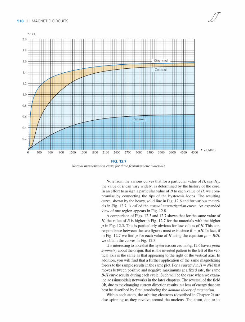
FIG. 12.7
Normal magnetization curve for three ferromagnetic materials.
Note from the various curves that for a particular value of H, say, Hx ,the value of B can vary widely, as determined by the history of the core.In an effort to assign a particular value of B to each value of H, we com-promise by connecting the tips of the hysteresis loops. The resultingcurve, shown by the heavy, solid line in Fig. 12.6 and for various materi-als in Fig. 12.7, is called the normal magnetization curve. An expandedview of one region appears in Fig. 12.8.
A comparison of Figs. 12.3 and 12.7 shows that for the same value ofH, the value of B is higher in Fig. 12.7 for the materials with the higherm in Fig. 12.3. This is particularly obvious for low values of H. This cor-respondence between the two figures must exist since B � mH. In fact, ifin Fig. 12.7 we find m for each value of H using the equation m � B/H,we obtain the curves in Fig. 12.3.
It is interesting to note that the hysteresis curves in Fig. 12.6 have a pointsymmetry about the origin; that is, the inverted pattern to the left of the ver-tical axis is the same as that appearing to the right of the vertical axis. Inaddition, you will find that a further application of the same magnetizingforces to the sample results in the same plot. For a current I in H � NI/l thatmoves between positive and negative maximums at a fixed rate, the sameB-H curve results during each cycle. Such will be the case when we exam-ine ac (sinusoidal) networks in the later chapters. The reversal of the field(�) due to the changing current direction results in a loss of energy that canbest be described by first introducing the domain theory of magnetism.
Within each atom, the orbiting electrons (described in Chapter 2) arealso spinning as they revolve around the nucleus. The atom, due to its
boy30444_ch12.qxd 3/22/06 1:13 PM Page 518

HYSTERESIS ⏐⏐⏐ 519
1.4
B (T)
H (At/m)
1.3
1.2
1.1
1.0
0.9
0.8
0.7
0.6
0.5
0.4
0.3
0.2
0.1
0 100 200 300 400 500 600 700
Cast steel
Sheet steel
Cast iron
FIG. 12.8
Expanded view of Fig. 12.7 for the low magnetizing force region.
boy30444_ch12.qxd 3/22/06 1:13 PM Page 519

520 ⏐⏐⏐ MAGNETIC CIRCUITS
(a) (b)
S N
FIG. 12.9
Demonstrating the domain theory of magnetism.
spinning electrons, has a magnetic field associated with it. In nonmag-netic materials, the net magnetic field is effectively zero since the mag-netic fields due to the atoms of the material oppose each other. Inmagnetic materials such as iron and steel, however, the magnetic fieldsof groups of atoms numbering in the order of 1012 are aligned, formingvery small bar magnets. This group of magnetically aligned atoms iscalled a domain. Each domain is a separate entity; that is, each domainis independent of the surrounding domains. For an unmagnetized sampleof magnetic material, these domains appear in a random manner, such asshown in Fig. 12.9(a). The net magnetic field in any one direction is zero.
TABLE 12.1
Electric MagneticCircuits Circuits
Cause E �Effect I �Opposition R �
When an external magnetizing force is applied, the domains that arenearly aligned with the applied field grow at the expense of the less favor-ably oriented domains, such as shown in Fig. 12.9(b). Eventually, if a suf-ficiently strong field is applied, all of the domains have the orientation ofthe applied magnetizing force, and any further increase in external field willnot increase the strength of the magnetic flux through the core—a condi-tion referred to as saturation. The elasticity of the above is evidenced by thefact that when the magnetizing force is removed, the alignment is lost tosome measure, and the flux density drops to BR. In other words, the removalof the magnetizing force results in the return of a number of misaligned do-mains within the core. The continued alignment of a number of the do-mains, however, accounts for our ability to create permanent magnets.
At a point just before saturation, the opposing unaligned domains arereduced to small cylinders of various shapes referred to as bubbles. Thesebubbles can be moved within the magnetic sample through the applica-tion of a controlling magnetic field. These magnetic bubbles form the ba-sis of the recently designed bubble memory system for computers.
12.7 AMPÈRE’S CIRCUITAL LAW
As mentioned in the introduction to this chapter, there is a broad similar-ity between the analyses of electric and magnetic circuits. This has al-ready been demonstrated to some extent for the quantities in Table 12.1.
If we apply the “cause” analogy to Kirchhoff’s voltage law (ΣA V �0), we obtain the following:
(for magnetic circuits) (12.9)
which, in words, states that the algebraic sum of the rises and drops of themmf around a closed loop of a magnetic circuit is equal to zero; that is,the sum of the rises in mmf equals the sum of the drops in mmf around aclosed loop.
Eq. (12.9) is referred to as Ampère’s circuital law. When it is appliedto magnetic circuits, sources of mmf are expressed by the equation
(At) (12.10)f � NI
�A f � 0
boy30444_ch12.qxd 3/22/06 1:13 PM Page 520

SERIES MAGNETIC CIRCUITS: DETERMINING NI ⏐⏐⏐ 521
The equation for the mmf drop across a portion of a magnetic circuit canbe found by applying the relationships listed in Table 12.1; that is, forelectric circuits,
V � IR
resulting in the following for magnetic circuits:
(At) (12.11)
where � is the flux passing through a section of the magnetic circuit and� is the reluctance of that section. The reluctance, however, is seldomcalculated in the analysis of magnetic circuits. A more practical equationfor the mmf drop is
(At) (12.12)
as derived from Eq. (12.6), where H is the magnetizing force on a sectionof a magnetic circuit and l is the length of the section.
As an example of Eq. (12.9), consider the magnetic circuit appearingin Fig. 12.10 constructed of three different ferromagnetic materials.
Applying Ampère’s circuital law, we have
f � Hl
f � £r
Iron�a
c
b
Steel
CobaltI
I
N turns
FIG. 12.10
Series magnetic circuit of three different materials.
� � � 0�NI � Hablab � Hbclbc � Hcalca � 0
NI � Hablab � Hbclbc � Hcalca
Drop
mmf dropsImpressedmmf
Rise Drop Drop
All the terms of the equation are known except the magnetizing forcefor each portion of the magnetic circuit, which can be found by usingthe B-H curve if the flux density B is known.
12.8 FLUX �
If we continue to apply the relationships described in the previous sec-tion to Kirchhoff’s current law, we find that the sum of the fluxes enter-ing a junction is equal to the sum of the fluxes leaving a junction; that is,for the circuit in Fig. 12.11,
�a � �b � �c (at junction a)or �b � �c � �a (at junction b)
both of which are equivalent.
12.9 SERIES MAGNETIC CIRCUITS:DETERMINING NI
We are now in a position to solve a few magnetic circuit problems, whichare basically of two types. In one type, � is given, and the impressed mmfNI must be computed. This is the type of problem encountered in the de-sign of motors, generators, and transformers. In the other type, NI isgiven, and the flux � of the magnetic circuit must be found. This type ofproblem is encountered primarily in the design of magnetic amplifiersand is more difficult since the approach is “hit or miss.”
�a
a
I
I
N
b
�c
�a �c
�b
FIG. 12.11
Flux distribution of a series-parallel magnetic network.
boy30444_ch12.qxd 3/22/06 1:13 PM Page 521
522 ⏐⏐⏐ MAGNETIC CIRCUITS
As indicated in earlier discussions, the value of m varies from point topoint along the magnetization curve. This eliminates the possibility offinding the reluctance of each “branch” or the “total reluctance” of a net-work, as was done for electric circuits where r had a fixed value for anyapplied current or voltage. If the total reluctance can be determined, � canthen be determined using the Ohm’s law analogy for magnetic circuits.
For magnetic circuits, the level of B or H is determined from the otherusing the B-H curve, and m is seldom calculated unless asked for.
An approach frequently used in the analysis of magnetic circuits is thetable method. Before a problem is analyzed in detail, a table is preparedlisting in the far left column the various sections of the magnetic circuit(see Table 12.2). The columns on the right are reserved for the quantitiesto be found for each section. In this way, when you are solving a prob-lem, you can keep track of what the next step should be and what is re-quired to complete the problem. After a few examples, the usefulness ofthis method should become clear.
This section considers only series magnetic circuits in which the flux� is the same throughout. In each example, the magnitude of the mag-netomotive force is to be determined.
TABLE 12.2
Section � (Wb) A (m2) B (T) H (At/m) l (m) Hl (At)
One continuous section 4 � 10�4 2 � 10�3 0.16
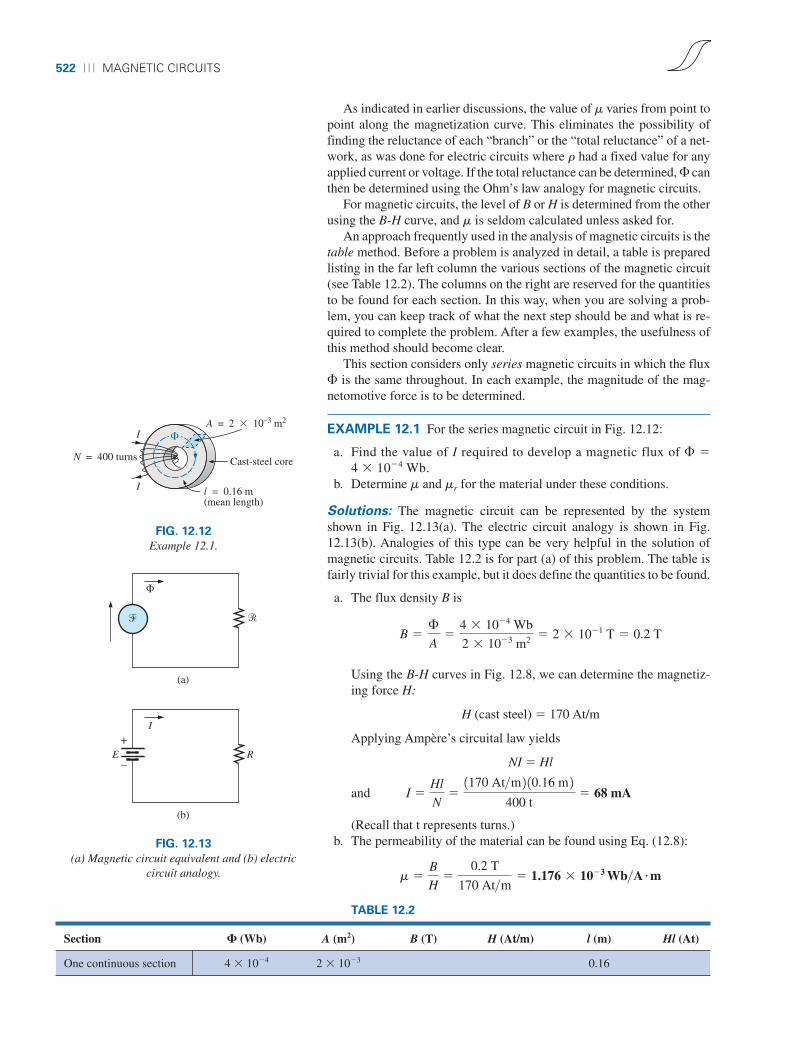
Cast-steel coreN = 400 turns
I
I
A = 2 � 10–3 m2
l = 0.16 m(mean length)
�
FIG. 12.12
Example 12.1.
�
� �
I
RE
(a)
(b)
+
–
FIG. 12.13
(a) Magnetic circuit equivalent and (b) electriccircuit analogy.
EXAMPLE 12.1 For the series magnetic circuit in Fig. 12.12:
a. Find the value of I required to develop a magnetic flux of � �4 � 10�4 Wb.
b. Determine m and mr for the material under these conditions.
Solutions: The magnetic circuit can be represented by the systemshown in Fig. 12.13(a). The electric circuit analogy is shown in Fig.12.13(b). Analogies of this type can be very helpful in the solution ofmagnetic circuits. Table 12.2 is for part (a) of this problem. The table isfairly trivial for this example, but it does define the quantities to be found.
a. The flux density B is
Using the B-H curves in Fig. 12.8, we can determine the magnetiz-ing force H:
H (cast steel) � 170 At/m
Applying Ampère’s circuital law yields
NI � Hl
and
(Recall that t represents turns.)b. The permeability of the material can be found using Eq. (12.8):
m �B
H�
0.2 T
170 At>m � 1.176 � 10�3 Wb>A m
I �Hl
N�1170 At>m 2 10.16 m 2
400 t� 68 mA
B �£
A�
4 � 10�4 Wb
2 � 10�3 m2 � 2 � 10�1 T � 0.2 T
boy30444_ch12.qxd 3/22/06 1:13 PM Page 522

SERIES MAGNETIC CIRCUITS: DETERMINING NI ⏐⏐⏐ 523
and the relative permeability is
EXAMPLE 12.2 The electromagnet in Fig. 12.14 has picked up a sec-tion of cast iron. Determine the current I required to establish the indi-cated flux in the core.
Solution: To be able to use Figs. 12.7 and 12.8, we must first convertto the metric system. However, since the area is the same throughout, wecan determine the length for each material rather than work with the in-dividual sections:
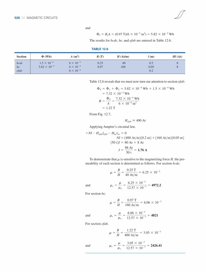
The information available from the efab and bcde specifications of theproblem has been inserted in Table 12.3. When the problem has beencompleted, each space will contain some information. Sufficient data tocomplete the problem can be found if we fill in each column from left toright. As the various quantities are calculated, they will be placed in asimilar table found at the end of the example.
1 in.2 a 1 m
39.37 in.b a 1 m
39.37 in.b � 6.452 � 10�4 m2
5 in. a 1 m
39.37 in.b � 127 � 10�3 m
12 in. a 1 m
39.37 in.b � 304.8 � 10�3 m
lbcde � 0.5 in. � 4 in. � 0.5 in. � 5 in. lefab � 4 in. � 4 in. � 4 in. � 12 in.
mr �m
mo�
1.176 � 10�3
4p � 10�7 � 935.83
N = 50 turnsSheet steel
Cast iron
f
e
d
a
b
c
�
lab = lcd = lef = lfa = 4 in.
lbc = lde = 0.5 in.
Area (throughout) = 1 in.2
� = 3.5 × 10⁻⁴ Wb
I I
FIG. 12.14
Electromagnet for Example 12.2.
TABLE 12.3
Section � (Wb) A (m2) B (T) H (At/m) l (m) Hl (At)
efab 3.5 � 10�4 6.452 � 10�4 304.8 � 10�3
bcde 3.5 � 10�4 6.452 � 10�4 127 � 10�3
The flux density for each section is
and the magnetizing force is
H (sheet steel, Fig. 12.8) � 70 At/mH (cast iron, Fig. 12.7) � 1600 At/m
Note the extreme difference in magnetizing force for each material forthe required flux density. In fact, when we apply Ampère’s circuital law,we find that the sheet steel section can be ignored with a minimal errorin the solution.
Determining Hl for each section yields
Hefablefab � (70 At/m)(304.8 � 10�3 m) � 21.34 AtHbcdelbcde � (1600 At/m)(127 � 10�3 m) � 203.2 At
B �£
A�
3.5 � 10�4 Wb
6.452 � 10�4 m2 � 0.542 T
boy30444_ch12.qxd 3/22/06 1:13 PM Page 523

524 ⏐⏐⏐ MAGNETIC CIRCUITS
The magnetic circuit equivalent and the electric circuit analogy for thesystem in Fig. 12.14 appear in Fig. 12.15.
Applying Ampère’s circuital law,
NI � Hefablefab � Hbcdelbcde
� 21.34 At � 203.2 At � 224.54 At
and (50 t)I � 224.54 At
so that
EXAMPLE 12.3 Determine the secondary current I2 for the transformerin Fig. 12.16 if the resultant clockwise flux in the core is 1.5 � 10�5 Wb.
I �224.54 At
50 t� 4.49 A
TABLE 12.4
Section � (Wb) A (m2) B (T) H (At/m) l (m) Hl (At)
efab 3.5 � 10�4 6.452 � 10�4 0.542 70 304.8 � 10�3 21.34bcde 3.5 � 10�4 6.452 � 10�4 0.542 1600 127 � 10�3 203.2
�
�efab
E
(a)
(b)
�bcde
Rbcde
Refab
+–
FIG. 12.15
(a) Magnetic circuit equivalent and (b) electriccircuit analogy for the electromagnet in Fig. 12.14. Area (throughout) = 0.15 × 10⁻³ m2
labcda = 0.16 m
I1 (2 A)
N1 = 60 turns
I1
a
d
b
c
Sheet steel�I2
N2 = 30 turns
I2
FIG. 12.16
Transformer for Example 12.3.
�abcda
�
�1 �2
Rabcda
I
E1 E2
(b)(a)
+
–
+
–
FIG. 12.17
(a) Magnetic circuit equivalent and (b) electric circuit analogy for the transformer in Fig. 12.16.
Solution: This is the first example with two magnetizing forces to con-sider. In the analogies in Fig. 12.17, note that the resulting flux of each isopposing, just as the two sources of voltage are opposing in the electriccircuit analogy.
Inserting the above data in Table 12.3 results in Table 12.4.
boy30444_ch12.qxd 3/22/06 1:13 PM Page 524

AIR GAPS ⏐⏐⏐ 525
The abcda structural data appear in Table 12.5.
TABLE 12.5
Section � (Wb) A (m2) B (T) H (At/m) l (m) Hl (At)
abcda 1.5 � 10�5 0.15 � 10�3 0.16
The flux density throughout is
and
Applying Ampère’s circuital law,
N1I1 � N2I2 � Habcdalabcda
(60 t)(2 A) � (30 t)(I2) � (20 At/m)(0.16m)120 At � (30 t)I2 � 3.2 At
and (30 t)I2 � 120 At � 3.2 At
or
For the analysis of most transformer systems, the equation N1I1 � N2I2
is used. This results in 4 A versus 3.89 A above. This difference is nor-mally ignored, however, and the equation N1I1 � N2I2 considered exact.
Because of the nonlinearity of the B-H curve, it is not possible to ap-ply superposition to magnetic circuits; that is, in Example 12.3, we can-not consider the effects of each source independently and then find thetotal effects by using superposition.
12.10 AIR GAPS
Before continuing with the illustrative examples, let us consider theeffects that an air gap has on a magnetic circuit. Note the presence ofair gaps in the magnetic circuits of the motor and meter in Fig. 11.15.The spreading of the flux lines outside the common area of the corefor the air gap in Fig. 12.18(a) is known as fringing. For our purposes,we shall ignore this effect and assume the flux distribution to be as inFig. 12.18(b).
The flux density of the air gap in Fig. 12.18(b) is given by
(12.13)
where, for our purposes,
�g � �core
and Ag � Acore
Bg �£g
Ag
I2 �116.8 At
30 t� 3.89 A
H 1from Fig. 12.8 2 � 1
51100 At>m 2 � 20 At>m
B �£
A�
1.5 � 10�5 Wb
0.15 � 10�3 m2 � 10 � 10�2 T � 0.10 T
�c
�c
(a)
�c
�c
(b)
�c
Air gap
fringing
FIG. 12.18
Air gaps: (a) with fringing; (b) ideal.
boy30444_ch12.qxd 3/22/06 1:13 PM Page 525
526 ⏐⏐⏐ MAGNETIC CIRCUITS
For most practical applications, the permeability of air is taken to beequal to that of free space. The magnetizing force of the air gap is thendetermined by
(12.14)
and the mmf drop across the air gap is equal to HgLg. An equation for Hg
is as follows:
and (At/m) (12.15)
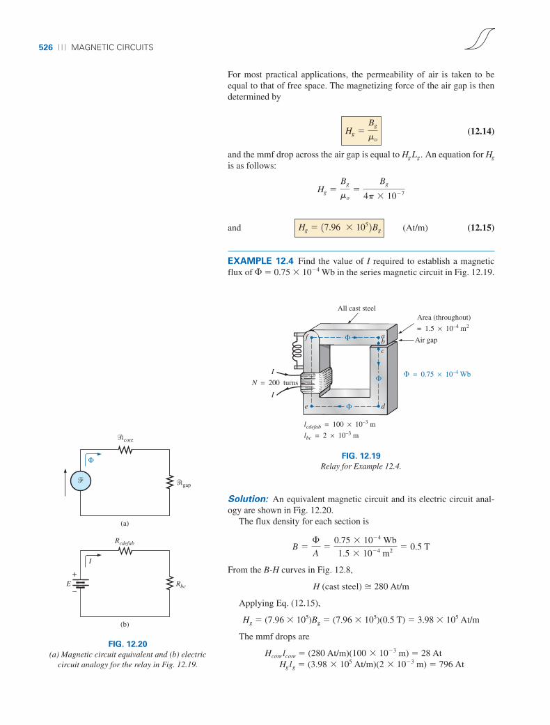
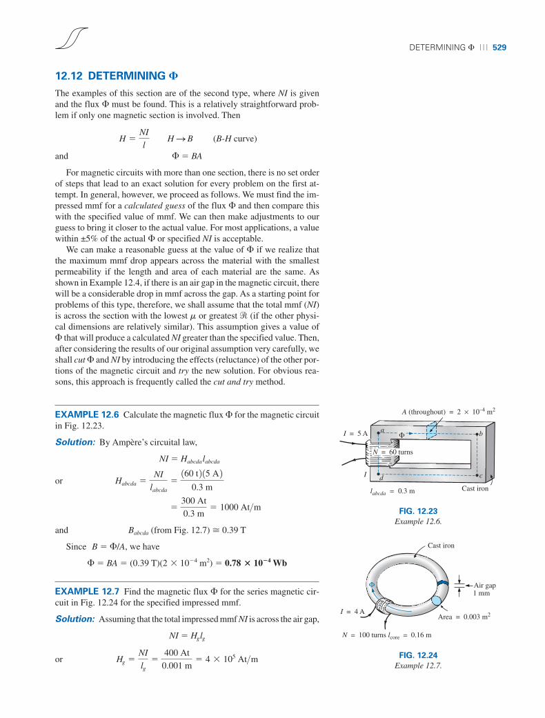
EXAMPLE 12.4 Find the value of I required to establish a magneticflux of � � 0.75 � 10�4 Wb in the series magnetic circuit in Fig. 12.19.
Hg � 17.96 � 105 2Bg
Hg �Bg
mo�
Bg
4p � 10�7
Hg �Bg
mo
N = 200 turns
All cast steel
Air gap
Area (throughout)
= 1.5 × 10⁻⁴ m2
� = 0.75 × 10⁻⁴ Wb
abc
de
f
I
I
lcdefab = 100 × 10–3 m
lbc = 2 × 10⁻³ m
�
�
�
FIG. 12.19
Relay for Example 12.4.�
�
I
E
(a)
�core
Rbc
Rcdefab
�gap
(b)
+
–
FIG. 12.20
(a) Magnetic circuit equivalent and (b) electriccircuit analogy for the relay in Fig. 12.19.
Solution: An equivalent magnetic circuit and its electric circuit anal-ogy are shown in Fig. 12.20.
The flux density for each section is
From the B-H curves in Fig. 12.8,
H (cast steel) � 280 At/m
Applying Eq. (12.15),
Hg � (7.96 � 105)Bg � (7.96 � 105)(0.5 T) � 3.98 � 105 At/m
The mmf drops are
Hcore lcore � (280 At/m)(100 � 10�3 m) � 28 AtHglg � (3.98 � 105 At/m)(2 � 10�3 m) � 796 At
B �£
A�
0.75 � 10�4 Wb
1.5 � 10�4 m2 � 0.5 T
boy30444_ch12.qxd 3/22/06 1:13 PM Page 526
SERIES-PARALLEL MAGNETIC CIRCUITS ⏐⏐⏐ 527
Applying Ampère’s circuital law,
NI � Hcore lcore � Hglg
� 28 At � 796 At(200 t)I � 824 At
I � 4.12 A
Note from the above that the air gap requires the biggest share (by far)of the impressed NI because air is nonmagnetic.
12.11 SERIES-PARALLEL MAGNETIC CIRCUITS
As one might expect, the close analogies between electric and magneticcircuits eventually lead to series-parallel magnetic circuits similar inmany respects to those encountered in Chapter 7. In fact, the electric cir-cuit analogy will prove helpful in defining the procedure to follow towarda solution.
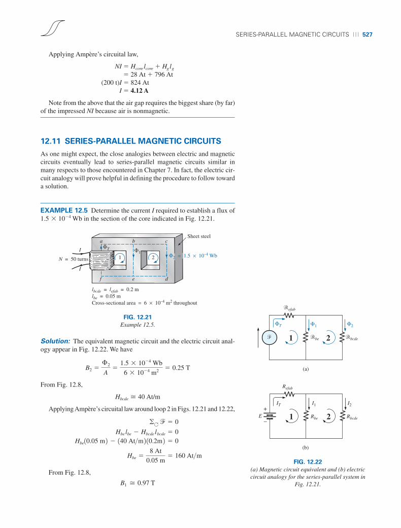
EXAMPLE 12.5 Determine the current I required to establish a flux of1.5 � 10�4 Wb in the section of the core indicated in Fig. 12.21.
Sheet steel
I
I
a b c
f e d
1 2N = 50 turns
�1�T
lbcde = lefab = 0.2 mlbe = 0.05 mCross-sectional area = 6 × 10⁻⁴ m2 throughout
�2 = 1.5 × 10⁻⁴ Wb
FIG. 12.21
Example 12.5.
Solution: The equivalent magnetic circuit and the electric circuit anal-ogy appear in Fig. 12.22. We have
From Fig. 12.8,
Hbcde � 40 At/m
Applying Ampère’s circuital law around loop 2 in Figs. 12.21 and 12.22,
From Fig. 12.8,
B1 � 0.97 T
Hbe �8 At
0.05 m� 160 At>m
Hbe10.05 m 2 � 140 At>m 2 10.2m 2 � 0 Hbelbe � Hbcde lbcde � 0
�A � � 0
B2 �£2
A�
1.5 � 10�4 Wb
6 � 10�4 m2 � 0.25 T
�efab
�T
� �be �bcde
�1 �2
1 2
(a)
Refab
IT I1
1 2Rbe Rbcde
I2
E
(b)
+
–
FIG. 12.22
(a) Magnetic circuit equivalent and (b) electriccircuit analogy for the series-parallel system in
Fig. 12.21.
boy30444_ch12.qxd 3/22/06 1:13 PM Page 527
528 ⏐⏐⏐ MAGNETIC CIRCUITS
and
�1 � B1A � (0.97 T)(6 � 10�4 m2) � 5.82 � 10�4 Wb
The results for bcde, be, and efab are entered in Table 12.6.
TABLE 12.6
Section � (Wb) A (m2) B (T) H (At/m) l (m) Hl (At)
bcde 1.5 � 10�4 6 � 10�4 0.25 40 0.2 8be 5.82 � 10�4 6 � 10�4 0.97 160 0.05 8efab 6 � 10�4 0.2
Table 12.6 reveals that we must now turn our attention to section efab:
From Fig. 12.7,
Hefab � 400 At
Applying Ampère’s circuital law,
� 1.22 T
B �£T
A�
7.32 � 10�4 Wb
6 � 10�4 m2
� 7.32 � 10�4 Wb
£T � £1 � £2 � 5.82 � 10�4 Wb � 1.5 � 10�4 Wb
I �88 At
50 t� 1.76 A
150 t 2I � 80 At � 8 At NI � 1400 At>m 2 10.2 m 2� 1160 At>m 2 10.05 m 2 �NI � Hefab lefab � Hbe lbe � 0
To demonstrate that m is sensitive to the magnetizing force H, the per-meability of each section is determined as follows. For section bcde,
and
For section be,
and
For section efab,
and mr �m
mo�
3.05 � 10�3
12.57 � 10�7 � 2426.41
m �B
H�
1.22 T
400 At>m � 3.05 � 10�3
mr �m
mo�
6.06 � 10�3
12.57 � 10�7 � 4821
m �B
H�
0.97 T
160 At>m � 6.06 � 10�3
mr �m
mo�
6.25 � 10�3
12.57 � 10�7 � 4972.2
m �B
H�
0.25 T
40 At>m � 6.25 � 10�3
boy30444_ch12.qxd 3/22/06 1:14 PM Page 528
DETERMINING � ⏐⏐⏐ 529
12.12 DETERMINING �
The examples of this section are of the second type, where NI is givenand the flux � must be found. This is a relatively straightforward prob-lem if only one magnetic section is involved. Then
(B-H curve)
and � � BA
For magnetic circuits with more than one section, there is no set orderof steps that lead to an exact solution for every problem on the first at-tempt. In general, however, we proceed as follows. We must find the im-pressed mmf for a calculated guess of the flux � and then compare thiswith the specified value of mmf. We can then make adjustments to ourguess to bring it closer to the actual value. For most applications, a valuewithin ±5% of the actual � or specified NI is acceptable.
We can make a reasonable guess at the value of � if we realize thatthe maximum mmf drop appears across the material with the smallestpermeability if the length and area of each material are the same. Asshown in Example 12.4, if there is an air gap in the magnetic circuit, therewill be a considerable drop in mmf across the gap. As a starting point forproblems of this type, therefore, we shall assume that the total mmf (NI)is across the section with the lowest m or greatest � (if the other physi-cal dimensions are relatively similar). This assumption gives a value of� that will produce a calculated NI greater than the specified value. Then,after considering the results of our original assumption very carefully, weshall cut � and NI by introducing the effects (reluctance) of the other por-tions of the magnetic circuit and try the new solution. For obvious rea-sons, this approach is frequently called the cut and try method.
EXAMPLE 12.6 Calculate the magnetic flux � for the magnetic circuitin Fig. 12.23.
Solution: By Ampère’s circuital law,
NI � Habcdalabcda
or
and Babcda (from Fig. 12.7) � 0.39 T
Since B � �/A, we have
� � BA � (0.39 T)(2 � 10�4 m2) � 0.78 � 10�4 Wb
EXAMPLE 12.7 Find the magnetic flux � for the series magnetic cir-cuit in Fig. 12.24 for the specified impressed mmf.
Solution: Assuming that the total impressed mmf NI is across the air gap,
NI � Hglg
or Hg �NI
lg�
400 At
0.001 m� 4 � 105 At>m
�300 At
0.3 m� 1000 At>m
Habcda �NI
labcda
�160 t 2 15 A 2
0.3 m
H �NI
l H S B
A (throughout) = 2 × 10⁻⁴ m2
a b
d c
Cast ironlabcda = 0.3 m
I
I = 5 A
N = 60 turns
�
FIG. 12.23
Example 12.6.
Cast iron
Air gap1 mm
Area = 0.003 m2I = 4 A
N = 100 turns lcore = 0.16 m
Φ
FIG. 12.24
Example 12.7.
boy30444_ch12.qxd 3/22/06 1:14 PM Page 529
530 ⏐⏐⏐ MAGNETIC CIRCUITS
TABLE 12.7
Section � (Wb) A (m2) B (T) H (At/m) l (m) Hl (At)
Core 1.51 � 10�3 0.003 0.503 1500 (B-H curve) 0.16Gap 1.51 � 10�3 0.003 0.503 4 � 105 0.001 400
and Bg � µoHg � (4p � 10�7)(4 � 105 At/m)� 0.503 T
The flux
�g � �core � BgA� (0.503 T)(0.003 m2)
�core � 1.51 � 10�3 Wb
Using this value of �, we can find NI. The core and gap data are in-serted in Table 12.7.
Hcorelcore � (1500 At/m)(0.16 m) � 240 At
Applying Ampère’s circuital law results in
NI � Hcorelcore � Hglg
� 240 At � 400 At400 At � 640 At
Since we neglected the reluctance of all the magnetic paths but the airgap, the calculated value is greater than the specified value. We musttherefore reduce this value by including the effect of these reluctances.Since approximately (640 At � 400 At)/640 At � 240 At/640 At �37.5% of our calculated value is above the desired value, let us reduce �by 30% and see how close we come to the impressed mmf of 400 At:
� � (1 � 0.3)(1.51 � 10�3 Wb)� 1.057 � 10�3 Wb
See Table 12.8.
TABLE 12.8
Section � (Wb) A (m2) B (T) H (At/m) l (m) Hl (At)
Core 1.057 � 10�3 0.003 0.16Gap 1.057 � 10�3 0.003 0.001
From the B-H curves,
Hcore � 850 At/mHcorelcore � (850 At/m)(0.16 m) � 136 At
Applying Ampère’s circuital law yields
NI � Hcorelcore � Hglg
� 136 At � 280.19 At400 At � 416.19 At (but within 5% and therefore
acceptable)
� 280.19 At � 17.96 � 105 2 10.352 T 2 10.001 m 2
HgIg � 17.96 � 105 2BgIg
B �£
A�
1.057 � 10�3 Wb
0.003 m3 � 0.352 T
boy30444_ch12.qxd 3/22/06 1:14 PM Page 530

APPLICATIONS ⏐⏐⏐ 531
The solution is, therefore,
� � 1.057 � 10�3 Wb
12.13 APPLICATIONS
Speakers and Microphones
Electromagnetic effects are the moving force in the design of speakerssuch as the one shown in Fig. 12.25. The shape of the pulsating waveformof the input current is determined by the sound to be reproduced by thespeaker at a high audio level. As the current peaks and returns to the val-leys of the sound pattern, the strength of the electromagnet varies in ex-actly the same manner. This causes the cone of the speaker to vibrate at afrequency directly proportional to the pulsating input. The higher the pitchof the sound pattern, the higher the oscillating frequency between thepeaks and valleys and the higher the frequency of vibration of the cone.
A second design used more frequently in more expensive speaker sys-tems appears in Fig. 12.26. In this case, the permanent magnet is fixed,and the input is applied to a movable core within the magnet, as shownin the figure. High peaking currents at the input produce a strong flux pat-tern in the voice coil, causing it to be drawn well into the flux pattern ofthe permanent magnet. As occurred for the speaker in Fig. 12.25, the corethen vibrates at a rate determined by the input and provides the audiblesound.
Sound
i
i
i
Magnetic sample(free to move)
Electromagnet
Flexible cone
FIG. 12.25
Speaker.
i i
Magnetizedferromagneticmaterial
(b) (c)
Magnetic gap
Magnet
Voice coil
Lead terminal
Magnet
Cone
(a)
FIG. 12.26
Coaxial high-fidelity loudspeaker: (a) construction: (b) basic operation; (c) cross section of actual unit.(Courtesy of Electro-Voice, Inc.)
Microphones also employ electromagnetic effects. The incomingsound causes the core and attached moving coil to move within the mag-netic field of the permanent magnet. Through Faraday’s law (e �N df/dt), a voltage is induced across the movable coil proportional to thespeed with which it is moving through the magnetic field. The resultinginduced voltage pattern can then be amplified and reproduced at a muchhigher audio level through the use of speakers, as described earlier. Mi-crophones of this type are the most frequently employed, although other
boy30444_ch12.qxd 3/22/06 1:14 PM Page 531

532 ⏐⏐⏐ MAGNETIC CIRCUITS
types that use capacitive, carbon granular, and piezoelectric* effects areavailable. This particular design is commercially referred to as a dynamicmicrophone.
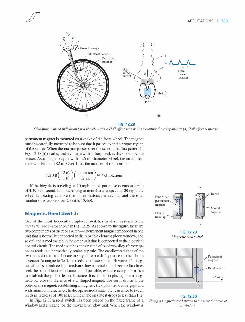
Hall Effect Sensor
The Hall effect sensor is a semiconductor device that generates an outputvoltage when exposed to a magnetic field. The basic construction con-sists of a slab of semiconductor material through which a current ispassed, as shown in Fig. 12.27(a). If a magnetic field is applied as shownin the figure perpendicular to the direction of the current, a voltage VH isgenerated between the two terminals, as indicated in Fig. 12.27(a). Thedifference in potential is due to the separation of charge established bythe Lorentz force first studied by Professor Hendrick Lorentz in the late1800s. He found that electrons in a magnetic field are subjected to a forceproportional to the velocity of the electrons through the field and thestrength of the magnetic field. The direction of the force is determined bythe left-hand rule. Simply place the index finger of your left hand in thedirection of the magnetic field, with the second finger at right angles tothe index finger in the direction of conventional current through the semi-conductor material, as shown in Fig. 12.27(b). The thumb, if placed atright angles to the index finger, will indicate the direction of the force onthe electrons. In Fig. 12.27(b), the force causes the electrons to accumu-late in the bottom region of the semiconductor (connected to the negativeterminal of the voltage VH), leaving a net positive charge in the upper re-gion of the material (connected to the positive terminal of VH). Thestronger the current or strength of the magnetic field, the greater the in-duced voltage VH.
In essence, therefore, the Hall effect sensor can reveal the strength ofa magnetic field or the level of current through a device if the other de-termining factor is held fixed. Two applications of the sensor are there-fore apparent—to measure the strength of a magnetic field in the vicinityof a sensor (for an applied fixed current) and to measure the level of cur-rent through a sensor (with knowledge of the strength of the magneticfield linking the sensor). The gaussmeter in Fig. 11.14 uses a Hall effectsensor. Internal to the meter, a fixed current is passed through the sensorwith the voltage VH indicating the relative strength of the field. Throughamplification, calibration, and proper scaling, the meter can display therelative strength in gauss.
The Hall effect sensor has a broad range of applications that are oftenquite interesting and innovative. The most widespread is as a trigger foran alarm system in large department stores, where theft is often a diffi-cult problem. A magnetic strip attached to the merchandise sounds analarm when a customer passes through the exit gates without paying forthe product. The sensor, control current, and monitoring system arehoused in the exit fence and react to the presence of the magnetic field asthe product leaves the store. When the product is paid for, the cashier re-moves the strip or demagnetizes the strip by applying a magnetizing forcethat reduces the residual magnetism in the strip to essentially zero.
The Hall effect sensor is also used to indicate the speed of a bicycle ona digital display conveniently mounted on the handlebars. As shown inFig. 12.28(a), the sensor is mounted on the frame of the bike, and a small
(a)
(b)
(conventionalflow)
I
+
–
VH
B
+
–
VH
++++++++++++++++
– – – – – – – – – – – – – – – –
I
e– e– e– e–
Magnetic fieldinto page
I
FIG. 12.27
Hall effect sensor: (a) orientation of controllingparameters; (b) effect on electron flow.
*Piezoelectricity is the generation of a small voltage by exerting pressure across certaincrystals.
boy30444_ch12.qxd 3/22/06 1:14 PM Page 532
APPLICATIONS ⏐⏐⏐ 533
permanent magnet is mounted on a spoke of the front wheel. The magnetmust be carefully mounted to be sure that it passes over the proper regionof the sensor. When the magnet passes over the sensor, the flux pattern inFig. 12.28(b) results, and a voltage with a sharp peak is developed by thesensor. Assuming a bicycle with a 26-in.-diameter wheel, the circumfer-ence will be about 82 in. Over 1 mi, the number of rotations is
If the bicycle is traveling at 20 mph, an output pulse occurs at a rateof 4.29 per second. It is interesting to note that at a speed of 20 mph, thewheel is rotating at more than 4 revolutions per second, and the totalnumber of rotations over 20 mi is 15,460.
Magnetic Reed Switch
One of the most frequently employed switches in alarm systems is themagnetic reed switch shown in Fig. 12.29. As shown by the figure, there aretwo components of the reed switch—a permanent magnet embedded in oneunit that is normally connected to the movable element (door, window, andso on) and a reed switch in the other unit that is connected to the electricalcontrol circuit. The reed switch is constructed of two iron-alloy (ferromag-netic) reeds in a hermetically sealed capsule. The cantilevered ends of thetwo reeds do not touch but are in very close proximity to one another. In theabsence of a magnetic field, the reeds remain separated. However, if a mag-netic field is introduced, the reeds are drawn to each other because flux linesseek the path of least reluctance and, if possible, exercise every alternativeto establish the path of least reluctance. It is similar to placing a ferromag-netic bar close to the ends of a U-shaped magnet. The bar is drawn to thepoles of the magnet, establishing a magnetic flux path without air gaps andwith minimum reluctance. In the open-circuit state, the resistance betweenreeds is in excess of 100 M�, while in the on state it drops to less than 1 �.
In Fig. 12.30 a reed switch has been placed on the fixed frame of awindow and a magnet on the movable window unit. When the window is
5280 ft a 12 in.
1 ftb a 1 rotation
82 in.b� 773 rotations
(a)
I (from battery)
Hall effect sensorPermanentmagnet
I
+ –VH
(b)
Halleffectsensor
B
VH
–
+
Spoke
MotionNS
Timefor onerotation
I I
FIG. 12.28
Obtaining a speed indication for a bicycle using a Hall effect sensor: (a) mounting the components; (b) Hall effect response.
Reeds
Sealedcapsule
Embeddedpermanentmagnet
Plastichousing
S
N
FIG. 12.29
Magnetic reed switch.
Permanentmagnet
Reed switch
Control
FIG. 12.30
Using a magnetic reed switch to monitor the state ofa window.
boy30444_ch12.qxd 3/22/06 1:14 PM Page 533
534 ⏐⏐⏐ MAGNETIC CIRCUITS
closed as shown in Fig. 12.30, the magnet and reed switch are sufficientlyclose to establish contact between the reeds, and a current is establishedthrough the reed switch to the control panel. In the armed state, the alarmsystem accepts the resulting current flow as a normal secure response. Ifthe window is opened, the magnet leaves the vicinity of the reed switch,and the switch opens. The current through the switch is interrupted, andthe alarm reacts appropriately.
One of the distinct advantages of the magnetic reed switch is that theproper operation of any switch can be checked with a portable magneticelement. Simply bring the magnet to the switch and note the output re-sponse. There is no need to continually open and close windows anddoors. In addition, the reed switch is hermetically enclosed so that oxi-dation and foreign objects cannot damage it, and the result is a unit thatcan last indefinitely. Magnetic reed switches are also available in othershapes and sizes, allowing them to be concealed from obvious view. Oneis a circular variety that can be set into the edge of a door and door jam,resulting in only two small visible disks when the door is open.
Magnetic Resonance Imaging
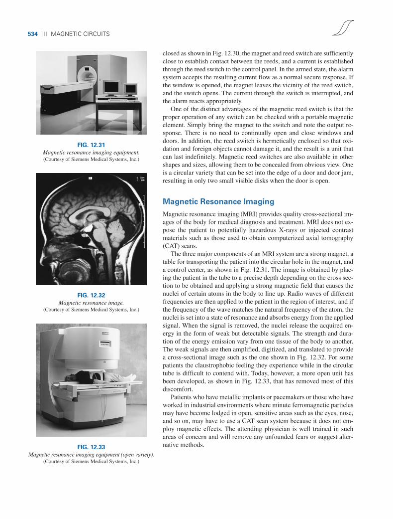
Magnetic resonance imaging (MRI) provides quality cross-sectional im-ages of the body for medical diagnosis and treatment. MRI does not ex-pose the patient to potentially hazardous X-rays or injected contrastmaterials such as those used to obtain computerized axial tomography(CAT) scans.
The three major components of an MRI system are a strong magnet, atable for transporting the patient into the circular hole in the magnet, anda control center, as shown in Fig. 12.31. The image is obtained by plac-ing the patient in the tube to a precise depth depending on the cross sec-tion to be obtained and applying a strong magnetic field that causes thenuclei of certain atoms in the body to line up. Radio waves of differentfrequencies are then applied to the patient in the region of interest, and ifthe frequency of the wave matches the natural frequency of the atom, thenuclei is set into a state of resonance and absorbs energy from the appliedsignal. When the signal is removed, the nuclei release the acquired en-ergy in the form of weak but detectable signals. The strength and dura-tion of the energy emission vary from one tissue of the body to another.The weak signals are then amplified, digitized, and translated to providea cross-sectional image such as the one shown in Fig. 12.32. For somepatients the claustrophobic feeling they experience while in the circulartube is difficult to contend with. Today, however, a more open unit hasbeen developed, as shown in Fig. 12.33, that has removed most of thisdiscomfort.
Patients who have metallic implants or pacemakers or those who haveworked in industrial environments where minute ferromagnetic particlesmay have become lodged in open, sensitive areas such as the eyes, nose,and so on, may have to use a CAT scan system because it does not em-ploy magnetic effects. The attending physician is well trained in suchareas of concern and will remove any unfounded fears or suggest alter-native methods.
FIG. 12.31
Magnetic resonance imaging equipment.(Courtesy of Siemens Medical Systems, Inc.)
FIG. 12.32
Magnetic resonance image.(Courtesy of Siemens Medical Systems, Inc.)
FIG. 12.33
Magnetic resonance imaging equipment (open variety).(Courtesy of Siemens Medical Systems, Inc.)
boy30444_ch12.qxd 3/22/06 1:14 PM Page 534

PROBLEMS ⏐⏐⏐ 535
SECTION 12.4 Ohm’s Law for Magnetic Circuits
5. Find the reluctance of a magnetic circuit if a magnetic flux� � 4.2 � 10�4 Wb is established by an impressed mmf of400 At.
6. Repeat Problem 5 for � � 72,000 maxwells and an im-pressed mmf of 120 gilberts.
SECTION 12.5 Magnetizing Force
7. Find the magnetizing force H for Problem 5 in SI units if themagnetic circuit is 6 in. long.
8. If a magnetizing force H of 600 At/m is applied to a mag-netic circuit, a flux density B of 1200 � 10�4 Wb/m2 is es-tablished. Find the permeability m of a material that willproduce twice the original flux density for the same mag-netizing force.
SECTIONS 12.6–12.9 Hysteresis through Series
Magnetic Circuits
9. For the series magnetic circuit in Fig. 12.36, determine thecurrent I necessary to establish the indicated flux.
PROBLEMS
SECTION 12.2 Magnetic Field
1. Using Appendix F, fill in the blanks in the following table.Indicate the units for each quantity.
� B
SI 5 � 10�4 Wb 8 � 10�4 TCGS ____________ ____________English ____________ ____________
2. Repeat Problem 1 for the following table if area � 2 in.2:
� B
SI ____________ ____________CGS 60,000 maxwells ____________English ____________ ____________
3. For the electromagnet in Fig. 12.34:a. Find the flux density in the core.b. Sketch the magnetic flux lines and indicate their direction.c. Indicate the north and south poles of the magnet.
Φ = 4 × 10⁻⁴ Wb
A = 0.01 m2
N turnsI I
FIG. 12.34
Problem 3.
3 in.
Iron
in.
(b)
1 cm
6 cm
Iron
2 cm
(a)
(c)
0.01 m
0.01 mIron
0.1 m
12
FIG. 12.35
Problem 4.
Area (throughout)= 3 × 10⁻³ m2
Cast iron
Φ = 10 × 10–4 WbMean length = 0.2 m
N = 75 turns
I
I
Φ
Φ
FIG. 12.36
Problem 9.
10. Find the current necessary to establish a flux of � � 3 �10�4 Wb in the series magnetic circuit in Fig 12.37.
Cast iron
N
ISheet steel
liron core = lsteel core = 0.3 mArea (throughout) = 5 � 10–4 m2
N = 100 turns
FIG. 12.37
Problem 10.
SECTION 12.3 Reluctance
4. Which section of Fig. 12.35—(a), (b), or (c)—has the largestreluctance to the setting up of flux lines through its longestdimension?
boy30444_ch12.qxd 3/22/06 1:14 PM Page 535

536 ⏐⏐⏐ MAGNETIC CIRCUITS
11. a. Find the number of turns N1 required to establish a flux� � 12 � 10�4 Wb in the magnetic circuit in Fig. 12.38.
b. Find the permeability m of the material.
I = 1 A
N2 = 30 turns
Area = 0.0012 m2
lm (mean length) = 0.2 m
lmN1
I =2 A
Cast steel
Φ
FIG. 12.38
Problem 11.
Cast steel
Sheet steel
Uniform area(throughout)= 1 in.2
lcast steel = 5.5 in.lsheet steel = 0.5 in.
NI
FIG. 12.39
Problem 12.
0.003 m
e
d
c
b
Sheet steel
a
f
Φ
N =100turns
I
Area (throughout) = 2 × 10⁻⁴ m2
lab = lef = 0.05 mlaf = lbe = 0.02 m
lbc = lde
I
FIG. 12.41
Problem 14.
I = 900 mAN = 80 turns
4 cm
f
Plunger
Chime
I
FIG. 12.42
Door chime for Problem 15.
0.002 mSheet steel
0.3 m
I2 = 0.3 AN2 = 40 turns
N1 = 200 turns
I1
I1
Φ
Area (throughout) = 1.3 × 10⁻⁴ m2
FIG. 12.43
Problem 16.
Cast steel
Cast iron
II
Area (throughout) = 0.25 in.2
lcast steel = 5.5 in.lcast iron = 2.5 in.
Φ = 0.8 � 10–4 Wb N1 = 20 turns
I
N2 = 30 turns
FIG. 12.40
Problem 13.
12. a. Find the mmf (NI) required to establish a flux � �80,000 lines in the magnetic circuit in Fig. 12.39.
b. Find the permeability of each material.
*13. For the series magnetic circuit in Fig. 12.40 with two im-pressed sources of magnetic “pressure,” determine the cur-rent I. Each applied mmf establishes a flux pattern in theclockwise direction.
SECTION 12.10 Air Gaps
14. a. Find the current I required to establish a flux � � 2.4 �10�4 Wb in the magnetic circuit in Fig. 12.41.
b. Compare the mmf drop across the air gap to that acrossthe rest of the magnetic circuit. Discuss your results us-ing the value of m for each material.
*15. The force carried by the plunger of the door chime inFig. 12.42 is determined by
(newtons)
where df/dx is the rate of change of flux linking the coil asthe core is drawn into the coil. The greatest rate of change offlux occurs when the core is 1⁄4 to 3⁄4 the way through. In thisregion, if � changes from 0.5 � 10�4 Wb to 8 � 10�4 Wb,what is the force carried by the plunger?
f �1
2 NI
df
dx
16. Determine the current I1 required to establish a flux of � �2 � 10�4 Wb in the magnetic circuit in Fig. 12.43.
boy30444_ch12.qxd 3/22/06 1:14 PM Page 536
GLOSSARY ⏐⏐⏐ 537
*17. a. A flux of 0.2 � 10�4 Wb will establish sufficient attrac-tive force for the armature of the relay in Fig. 12.44 toclose the contacts. Determine the required current to es-tablish this flux level if we assume that the total mmfdrop is across the air gap.
b. The force exerted on the armature is determined by theequation
where Bg is the flux density within the air gap and A is thecommon area of the air gap. Find the force in newtons ex-erted when the flux � specified in part (a) is established.
F1newtons 2 �1
2
Bg2 A
mo
Cast steel
Area =0.009 m2
0.08 m
N = 100 turns
I = 2 A
Φ
FIG. 12.46
Problem 19.
Cast steel
Φa b
f e
c
dN = 150 turns
I = 2 A
lcd = 8 × 10– 4 mlab = lbe = lef = lfa = 0.2 mArea (throughout) = 2 × 10– 4 m2
lbc = lde
FIG. 12.47
Problem 20.
SECTION 12.11 Series-Parallel Magnetic Circuits
*18. For the series-parallel magnetic circuit in Fig. 12.45, find thevalue of I required to establish a flux in the gap of �g � 2 �10�4 Wb.
SpringArmature Air gap = 0.2 cm
Contacts
CoilN = 200 turnsDiameter of core = 0.01 m
SolenoidI
FIG. 12.44
Relay for Problem 17.
Sheet steel throughout
N =200 turns
a
h g f
e
d
cb�T
I
�1
Area for sections other than bg = 5 × 10⁻⁴ m2
lab = lbg = lgh = lha = 0.2 mlbc = lfg = 0.1 m, lcd = lef = 0.099 m
Area =2 × 10⁻⁴ m2
1 2
0.002 m
�2
FIG. 12.45
Problem 18.
SECTION 12.12 Determining �
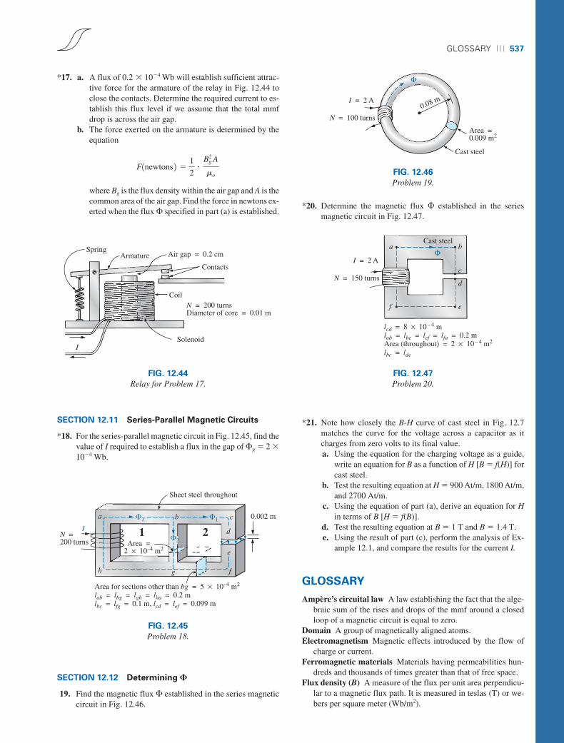
19. Find the magnetic flux � established in the series magneticcircuit in Fig. 12.46.
*20. Determine the magnetic flux � established in the seriesmagnetic circuit in Fig. 12.47.
*21. Note how closely the B-H curve of cast steel in Fig. 12.7matches the curve for the voltage across a capacitor as itcharges from zero volts to its final value.a. Using the equation for the charging voltage as a guide,
write an equation for B as a function of H [B � f(H)] forcast steel.
b. Test the resulting equation at H � 900 At/m, 1800 At/m,and 2700 At/m.
c. Using the equation of part (a), derive an equation for Hin terms of B [H � f(B)].
d. Test the resulting equation at B � 1 T and B � 1.4 T.e. Using the result of part (c), perform the analysis of Ex-
ample 12.1, and compare the results for the current I.
GLOSSARY
Ampère’s circuital law A law establishing the fact that the alge-braic sum of the rises and drops of the mmf around a closedloop of a magnetic circuit is equal to zero.
Domain A group of magnetically aligned atoms.Electromagnetism Magnetic effects introduced by the flow of
charge or current.Ferromagnetic materials Materials having permeabilities hun-
dreds and thousands of times greater than that of free space.Flux density (B) A measure of the flux per unit area perpendicu-
lar to a magnetic flux path. It is measured in teslas (T) or we-bers per square meter (Wb/m2).
boy30444_ch12.qxd 3/22/06 1:14 PM Page 537

538 ⏐⏐⏐ MAGNETIC CIRCUITS
Hysteresis The lagging effect between the flux density of a ma-terial and the magnetizing force applied.
Magnetic flux lines Lines of a continuous nature that reveal thestrength and direction of a magnetic field.
Magnetizing force (H) A measure of the magnetomotive forceper unit length of a magnetic circuit.
Magnetomotive force (mmf) (�) The “pressure” required to es-tablish magnetic flux in a ferromagnetic material. It is mea-sured in ampere-turns (At).
Permanent magnet A material such as steel or iron that will re-main magnetized for long periods of time without the aid ofexternal means.
Permeability (M) A measure of the ease with which magneticflux can be established in a material. It is measured in Wb/Am.
Relative permeability (Mr) The ratio of the permeability of amaterial to that of free space.
Reluctance (�) A quantity determined by the physical charac-teristics of a material that will provide an indication of the “re-luctance” of that material to the setting up of magnetic fluxlines in the material. It is measured in rels or At/Wb.
boy30444_ch12.qxd 3/22/06 1:14 PM Page 538