Embed Size (px)
Citation preview

12155.001 - Drill Jig Cookbook
Capacity 3/8” (0.9cm) to 2" (5.0cm) Outside Diameter Tube, Rod or Pipe
This document is the intellectual propertyof and copyright © by David Lee.
Please respect my hard workand do not share it with anyone.
I feel my selling price is quite reasonable so,if your friends are interested in this project, give him or her my e-mail address [[email protected]]
and encourage them to buy their own copy.
[Most recent update - Monday, January 25, 2016] Page 1 of 37
Illustration 1: Finished Drilling Jig

12155.001 - Drill Jig Cookbook
Table of ContentsForward.............................................................................................................................3Introduction.......................................................................................................................3Drawing Convention............................................................................................................3Axial Dimensioning..............................................................................................................3Angular Dimensioning..........................................................................................................4Welding Symbols................................................................................................................4Materials of Construction.....................................................................................................4Closed Tubing Ends.............................................................................................................4Recommended Tools............................................................................................................4Tolerances..........................................................................................................................5Templates..........................................................................................................................5Disclaimer..........................................................................................................................5Safety Warnings:................................................................................................................5Recommended Tools............................................................................................................612154, Final Assembly ........................................................................................................712154A, Final Assembly [Optional Configuration]....................................................................812155, Retainer................................................................................................................1212666, Base.....................................................................................................................1412167, Support.................................................................................................................1512345, Horizontal Retainer Segment...................................................................................18Final Assembly..................................................................................................................1912348, Support Angle........................................................................................................20Finishing the Project .........................................................................................................22Instructions for Use ..........................................................................................................22Appendix A.......................................................................................................................26
10-Minute Weld Symbols Lesson.....................................................................................26Appendix B.......................................................................................................................29
Tools You'll Need but May Not Have.................................................................................29Appendix C.......................................................................................................................32
List of Suppliers............................................................................................................32Appendix B.......................................................................................................................34
Commercial Parts:.........................................................................................................34
[Most recent update - Monday, January 25, 2016] Page 2 of 37

12155.001 - Drill Jig Cookbook
ForwardI'm an engineer bytrade and ametalcrafter by hobby.There’s nothing I likebetter than working inmy shop making stuffout of metal. Thisproject is not very
difficult but some of the drawings may look abit intimidating. They’re not really that bad ifyou take the time to study them andunderstand them. The templates supplied asan option are real time savers. The 11” X 17”drawings are also available. Please contact meat [email protected].
If you're an experienced craftsman and if youhave the right tools, you can probably make itover two weekend. If you’re a novice, it mayrequire a bit more time but there’s really noparticular rush. Take your time and have fun.
If you have any questions, I'm happy to help.Do not be concerned about writing or sendingan e-mail. I'm happy to hear from anyonemaking my projects.
I'm a mechanical engineer, Ben FranklinInstitute, class of 1965. I’ve worked inAerospace, Shipbuilding, Robotics andTelecommunications.
Did you ever want to cross drill a hole right,smack, dab in the middle of a tube or pipe? Ihave lots of times. Finally, one snowyafternoon with not much else to do, I sat downand designed a jig to do just that. The nextday I cut and formed the stock and built it. Itcame out so well, I put together this booklet soI could share it with others.
You could probably make the whole thing in anafternoon if you’re an experienced homecraftsman and if you have the right tools. Ityou’re a novice, this is an excellent project tolearn with.
IntroductionWelcome and thank you for purchasing the Drilljig Cookbook. I'm sure you're anxious to startcutting, drilling and welding but it would be agood idea to breeze through this briefintroduction first. In the following text, I’llexplain some things you should know beforeyou begin.
The jig shown on the cover was made using aHarbor Freight bender. After receiving feedbackfrom the first few crafters, I realized that Ishould provide for those who don't have aproper bender.
Drawing ConventionI've made the drawings in ANSI format. It’swhat I‘m familiar with and what I‘ve used tomake engineering drawings for over 30 years.I've purchased mail order drawing packagesmyself in the past. Some were comical, handdrawn cartoons. Most looked like they weredone on somebody's kitchen table with a rulerand lined paper while they were waiting for thecoffee to brew and none had much value. Isincerely hope you'll find my drawing packageeasy to follow, accurate and worthwhile. Myultimate goal is for you to have such a goodexperience with this project that you willpurchase my other plan and kits. The drawingsare all CAD generated and all the piece partsand sub assembly and assemblies wereactually made from the drawings. If you findany errors, please contact [email protected] or:
David S. Lee198 Summit Street
W. Franklin, NH 03235-1555
Axial DimensioningI've made the drawing available in inch/decimaland centimeter dimensioning. Many times,things just don't work out to an equal 32nd ofan inch or I don't dimension in fractions. If Ihad, SolidWorks would round things off to
[Most recent update - Monday, January 25, 2016] Page 3 of 37

12155.001 - Drill Jig Cookbook
wherever it's programmed to. This builds in anerror of as much as .015". If there are ten such‘round·offs' in an assembly and they all go inthe same direction, the result is a total error of.150" (.38cm) or over 1/8” if you're so inclined.
I use a tape graduated in centimeters. It cost awhopping $12.99. A decimal tape is the sameprice. All the parts and pieces shown here weremade fusing a centimeter tape. If you give it ashot, after about ½ day, you'll hopefully agreethat centimeters or inch/decimal are the way togo. If you're more comfortable with fractions,go for it. I'll send you the drawings in fractions.All the illustrative drawings in this manual areshown in centimeter dimension convention.The actual engineering drawings available foradditional cost order will be delineated inwhatever convention you want. Theillustrations in this booklet are dimensioned incentimeters.
Angular DimensioningAngular dimensioning is used on the drawingsfor reference only. I chose to show the anglesonly as reference dimensions because, forexample, over a 30" length at 30°, an angle of31° will result in nearly a .718" (1.8cm) errorin the opposite side. Please don't try to use aprotractor. Please use the axial coordinates tomake angle cuts.
Welding SymbolsI've uses AWS welding symbols in thedrawings. Although some appear a bitintimidating, they're really quite simple onceyou understand. Further along in this manualI've shown a simple explanation of the symbolsused. If you have any questions, e-mail me at:
Materials of ConstructionUnless I've specified otherwise, hot rolled steelis adequate for construction. Many folks callany steel that‘s not stainless 'cold-rolled' whenthey actually mean low carbon, mild steel.
M1010 hot rolled is a low carbon, generalpurpose, merchant quality steel which iseconomical and weldable. You can also use1008, 1018 or 1020 with satisfactory results. Ifyou have some steel stock lying around thatmeets the dimensional criteria and it can becut, drilled and welded, use it. If you got to asalvage yard to buy the stock and ask forM1010 hot rolled, you may get just a blankstare. Here's the ID end color:
M1010 - blackM102O - none1018 - ????
1018 & 1020 – green
Go to the rack, pick out what you want and payfor it.
Schedule pipe is rated, not actually by it's wallthickness but by its liquid water flow andworking strength. That's why 1/8", schedule 40pipe is over 3/8" OD and over 1/4" ID. Theformula for determining wall thickness is socomplex it's not smart to discussing it here.Unless the actual flow and strength areimportant, if the I wrote on the drawing "1¼inch pipe", use any stock that's somewhatround and over 1¼“ ID.
Closed Tubing EndsAll my creations are designed with closedtubing ends wherever possible. The reason isto keep from oxidizing the inside walls. Steelwon't corrode if it can't get oxygen. Since wecan't conveniently paint the inside wall of a twofoot long bar, we try to seal the ends. Oncethe iron in the steel uses up all the availableoxygen, it won't corrode any longer. I suggestyou make a conscientious effort to produce anairtight weld everywhere you can.
Recommended ToolsFarther along in this manual I've provided a listof recommended tools, both hand and power. If you don't have at least the minimum recommended apparatus you may want to reschedule construction for another time or use
[Most recent update - Monday, January 25, 2016] Page 4 of 37

12155.001 - Drill Jig Cookbook
this project as justification to buy some nice, new tools.
TolerancesNo dimensions are toleranced unless necessary. I recommend using a +/- .015" (.04cm) allowance as a general rule. In most cases, a +/- .030" won't matter much. If the feature or its location needs a tight tolerance, it will be noted on the drawing. The booklet text explains the function of each part and each feature of the part to allow you to make your own decision regarding +/- variation.
TemplatesIf you by the document package, included there-in will be a collection of full sized templates.nice, heavy 22 lb. paper. It's fine if you'd rather layout the hole centers with a square and scriber. I've found, however, that itis much easier and more accurate to use the templates. Cut on the outline with a hobby knife and metal straight edge. Tape the template accurately to the stock after you've cut it to the proper size. Lay the work down flat on a flat work surface and prick where the center lines cross with an automatic punch
first, then put in a good sized dent with a big center punch and hammer, strip off the template and drill.
DisclaimerI have not made and will not make anyrepresentation or warranty of merchantabilityor fitness or any other representation orwarranty not set forth here-in and I shall notbe held liable for any consequential or indirectdamage, including loss of life, as a result of theuse or misuse of the equipment describedhere-in. I do not assume liability orresponsibility for any personal injury, propertydamage or loss construed as a result ofpurchasing these documents.
Safety Warnings:1. D0 NOT operate or allow anyone else to
operate this deice without proper eye and hand protection.
2. DO NOT allow children under the age of12 years old to operate this deice.
3. DO NOT allow children under 18 yearsold to operate this device unlesssupervised by a responsible adult.
[Most recent update - Monday, January 25, 2016] Page 5 of 37

12155.001 - Drill Jig Cookbook
Recommended Tools
Function Minimum Recommended
CuttingReciprocating Power Saw or Abrasive Cut-off Saw (Chop Saw)
Cut-off (Horizontal Band) Saw
Drilling 3/8" Power Drill 1/2" Drill Press
Welding 100 amp Stick Welder 150 amp TIG or MIG Welder
Grinding 4½ " Power Grinder7" Power Grinder or 9” Power Grinder
Hand Tools
Hammer (16 oz)C-Clamp (6"), two each6' Tape Measure in Fractions12" Combination SquareCenter PunchAutomatic Center Punch1/8” Dia Twist Drill (Pilot Holes)5/16" Dia Twist Drill (Tap Drill)25/64” dia Twist Drill½” Dia Twist Drill3/8”-16 Tap & Handle
Hammer (32 oz)-----------------------2 meter or 6' Decimal Tape Measure----------------------------------------------------------------------------------------------------------------------------------------------------------------------------------------
[Most recent update - Monday, January 25, 2016] Page 6 of 37

12154.001 - Drill Jig Cookbook
12154, Final Assembly
[Most recent update - Monday, January 25, 2016] Page 7 of 37
Illustration 2: 12154, Final Assembly Isometric

12154.001 - Drill Jig Cookbook
12154A, Final Assembly [Optional Configuration]
[Most recent update - Monday, January 25, 2016] Page 8 of 37
Illustration 3: 12154A, Final Assembly [Optional Configuration]

12154.001 - Drill Jig Cookbook
[Most recent update - Monday, January 25, 2016] Page 9 of 37
Illustration 4: 12154, Final Assembly BOM

12155.001 - Drill Jig Cookbook
[Most recent update - Monday, January 25, 2016] Page 10 of 37
Illustration 5: Final Assembly Dimensional Outline

12155.001 - Drill Jig Cookbook
[Most recent update - Monday, January 25, 2016] Page 11 of 37
Illustration 6: 12154, Final Assembly Dimensional Outline [Optional Configuration]

12155.001 - Drill Jig Cookbook
12155, Retainer
[Most recent update - Monday, January 25, 2016] Page 12 of 37
Illustration 7: 12155, Retainer

12155.001 - Drill Jig Cookbook
The jig shown on the cover was made using a HarborFreight bender. After receiving feedback from the firstfew crafters, I realized that I should provide optionfor those who don’t have a proper bender. This revisedbooklet shows both configurations. If you’re making theversion with a welded stock retainer, please go to pageError: Reference source not found.This part,made from ¼” X 1¼” hot rolled steel flat, willeventually be welded to 12166 – Base. It is drawingnumber 12155. Fabrication it is a bit tricky. Cut size is20cm or so. That will leave a lot of excess forcorrecting after bending, which you’ll have to trim offlater. In most case, I recommend drilling before formingbut not this time.
Cut the ¼” X 1¼” stock to 20cm. I used a low-endbender that I purchased from Harbor Freight Tools(harborfreight.com) for short money. Their part numberwas 44094 at the time. Despite the low cost, itworked swell for me. See Appendix C for additionalinformation.
Scribe a line across the stock at8cm from one end. This iswhere the bend should start.You must clamp the stock to thebender as shown in the nextphoto (Figure 5). The bendshould start at about 2cm fromthe middle of the stock since thebend takes about 4cm. Thatwould be at the 8cm line.Bending with this tool is not anexact science. You should cutthe stock a bit oversized so youcan trim it later. Bend thestock back on itself (180° ). Irepeat, it’s a good idea to clampthe stock as shown in thefollowing photo. Locate the centerfrom both the width and lengthand prick with an automatic centerpunch. Get a big hammer andsolid center punch and put agood-sized dent at the prick mark. Drill a ¼” pilot hole at the center punch, then a 5/16” holefor 3/8-16 tap. Next, tap the hole. Finally, trim the piece to the dimension shown in thedrawing.
[Most recent update - Monday, January 25, 2016] Page 13 of 37
Illustration 8: 12155, Retainer Isometric
Illustration 9: Harbor Freight Bender #44094
12154.001 - Drill Jig Cookbook
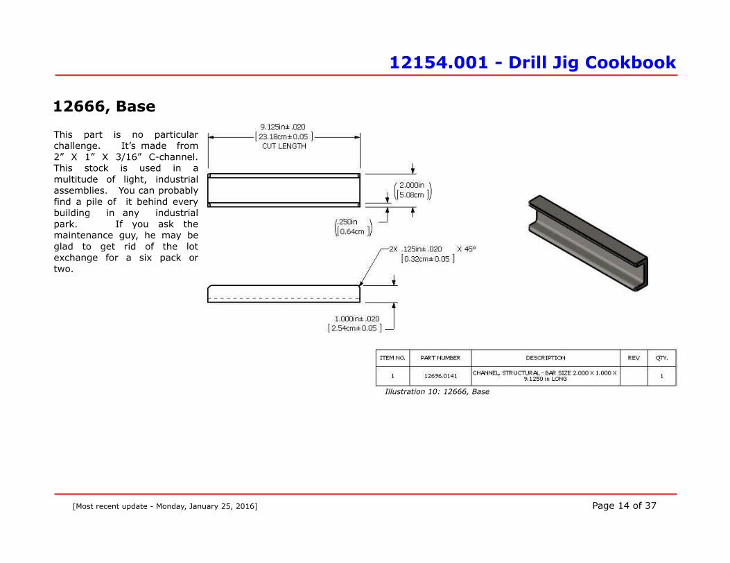
12666, Base
This part is no particularchallenge. It’s made from2” X 1” X 3/16” C-channel.This stock is used in amultitude of light, industrialassemblies. You can probablyfind a pile of it behind everybuilding in any industrialpark. If you ask themaintenance guy, he may beglad to get rid of the lotexchange for a six pack ortwo.
[Most recent update - Monday, January 25, 2016] Page 14 of 37
Illustration 10: 12666, Base

12154.001 - Drill Jig Cookbook
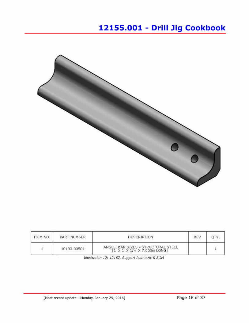
12167, SupportThis part must be made accurately. Start with 1¼” X1¼” X 3/16” bar size “L” angle. You may find a pile ofthis next to the channel you needed for the base(12166). You have to grind the point to a flat soit will clear the bottom of the base. The two ¼”holes must be as close to the inside apex as youcan manage. I started by pricking the two holelocations on the inside and then really slammed it witha solid center punch. This caused a great dent in thestock that was big enough so that a 1/8” bit wouldn’ttouch the legs. Next, I set the piece up on my drillpress table perfectly level, open side up, anddrilled the 1/8” pilot hole. I then flipped it overand drilled the two ¼“ diameter holes from theopposite side. You’re going to use a ¼“ transferpunch to set the jig up when it’s time to use it so thetwo holes must be attained with a new or freshly (andproperly) sharpened bit. If you get any wobble, thehole will wind up too large and it won’t be accurate.
[Most recent update - Monday, January 25, 2016] Page 15 of 37
Illustration 11: 12167, Support
12155.001 - Drill Jig Cookbook
[Most recent update - Monday, January 25, 2016] Page 16 of 37
Illustration 12: 12167, Support Isometric & BOM
12154.001 - Drill Jig Cookbook
[Most recent update - Monday, January 25, 2016] Page 17 of 37
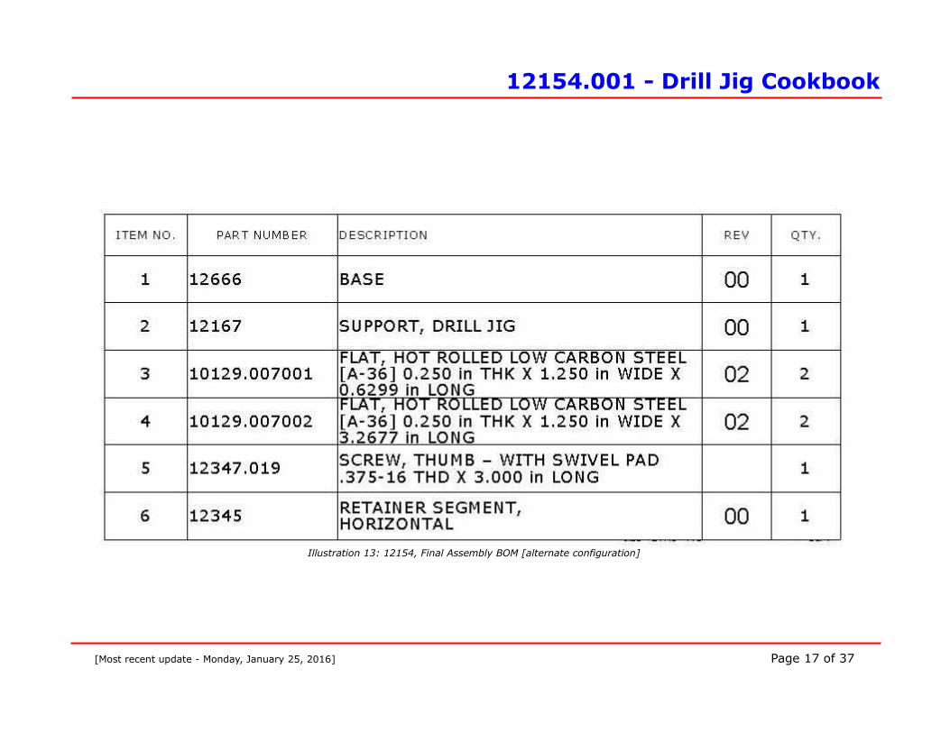
Illustration 13: 12154, Final Assembly BOM [alternate configuration]
12154.001 - Drill Jig Cookbook
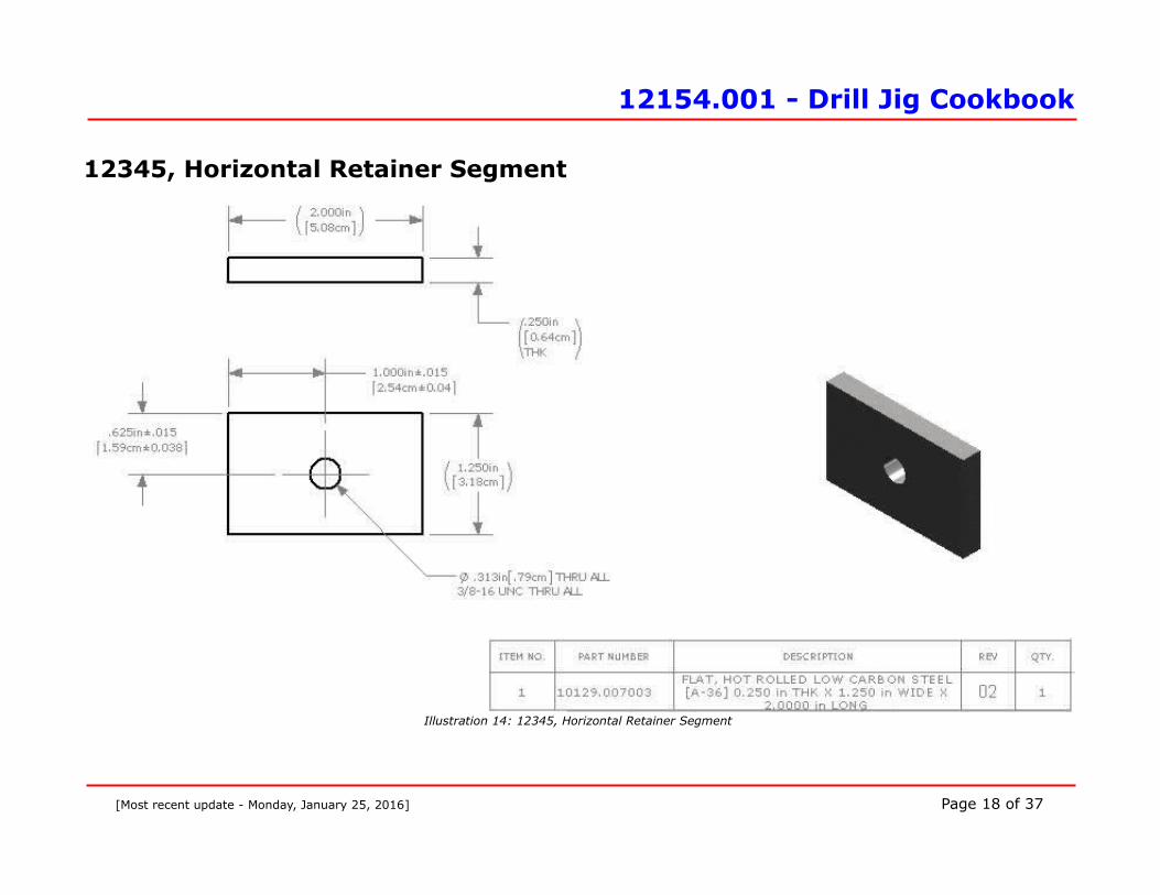
12345, Horizontal Retainer Segment
[Most recent update - Monday, January 25, 2016] Page 18 of 37
Illustration 14: 12345, Horizontal Retainer Segment
12154.001 - Drill Jig Cookbook
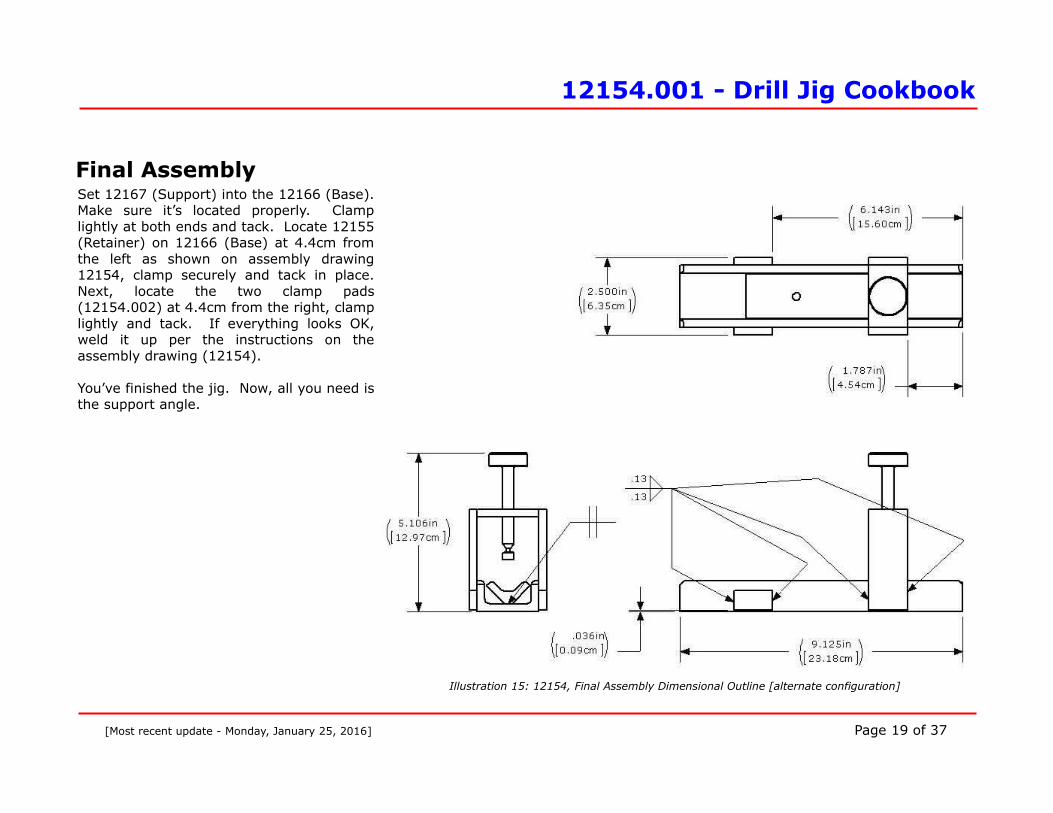
Final AssemblySet 12167 (Support) into the 12166 (Base).Make sure it’s located properly. Clamplightly at both ends and tack. Locate 12155(Retainer) on 12166 (Base) at 4.4cm fromthe left as shown on assembly drawing12154, clamp securely and tack in place.Next, locate the two clamp pads(12154.002) at 4.4cm from the right, clamplightly and tack. If everything looks OK,weld it up per the instructions on theassembly drawing (12154).
You’ve finished the jig. Now, all you need isthe support angle.
[Most recent update - Monday, January 25, 2016] Page 19 of 37
Illustration 15: 12154, Final Assembly Dimensional Outline [alternate configuration]

12155.001 - Drill Jig Cookbook
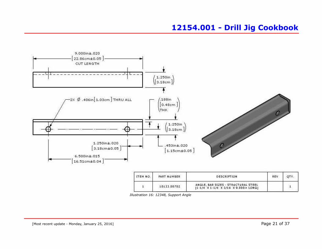
12348, Support Angle
My first thought was to drill holes in the base to match the holes in my drill press table butI had a few issues with that idea. First, the plans would only match my 60-year-old Delta drillpress table. Second, the device would be locked down and impossible to move aroundmaking finite adjustments unlikely. Third, locking down the jig may cause damage to thealignment hole if the piece is drilled through. Finally, I was concerned that the table slotlocation may wind up under the work angle. By employing an ancillary support angle, the basicdesign is compatible with any viable drill press of any age and it can be slid to any position fromright to left along the angle and the alignment with the chuck would remain true. The builder may omit the support angle and drill the appropriate holes in the base if he (or she)chooses. An alternative is to weld the support angle to the base. The problem in doing so is ifyou’re going to drill completely through the work, you may also drill into the alignment hole.Eventually, the alignment hole will be too large to be of any value.
[Most recent update - Monday, January 25, 2016] Page 20 of 37
12154.001 - Drill Jig Cookbook
[Most recent update - Monday, January 25, 2016] Page 21 of 37
Illustration 16: 12348, Support Angle

12155.001 - Drill Jig Cookbook
Finishing the Project You don’t really have to clean and paint your project. It will work OK unfinished but, if useinfrequently, it will rust in your toolbox and get all adjacent tool rusty too. I grit blasted minethen I wiped it down with acetone, primed and painted it. You have probably noticed that the jig shown in the photos is not exactly the same as thedrawing. I made a few improvements in the design after using mine a few times. In addition, Iused scrap stock that I’d been tripping over for years.
Instructions for Use
1. Lock a ¼“ transfer punch (see Appendix B for recommended tools) or ¼“ drill rod in thedrill press chuck and set the table so you can get the jig with the stock to be drilled justunder it.
2. Lock the table in place and don’t move it again until you’re done.
3. Align the jig so the punch is over one of the holes.
4. Lower the chuck so the punch penetrates the hole.
5. Clamp the jig securely to the table and tighten the chuck spindle travel clamp.
6. Locate the support angle in place as shown in Figure 13.
7. Insert and tighten the two support angle screws.
8. Clamp the jig to the support angle securely.
9. Remove the clamp in step 5.
10.Release the chuck spindle travel clamp and raise the drill chuck so the punch is clear of thejig and remove the transfer punch.
11. You can now slide the jig to the left so when you drill the stock the bit will miss thesupport. With this configuration, you can slide the jig left or right to make finiteadjustments without disturbing the alignment with the drill chuck.
12.Clamp the jig to the support angle using two clamps as shown in Figure 15.
13. Put the stock to be drilled in the jig (see Illustration 17) and clamp securely with the stockretainer screw. Hopefully, you’ve marked the stock where you want the hole.
14. It’s a good idea to use a center drill to start the hole. This will keep the next sized bit fromwandering.
[Most recent update - Monday, January 25, 2016] Page 22 of 37

12155.001 - Drill Jig Cookbook
15.Depending on what size hole you’re intending to drill, you may want to use a pilot bit first.I was only drilling a 3/16” hole, so I didn’t. Either way, if the bit isn’t sharpened properly,it will wander and you won’t be able to drill exactly through the neutral axis. This may ormay not be an important consideration depending on whether the strength of the finishedpart is of concern. See Illustration 17.
[Most recent update - Monday, January 25, 2016] Page 23 of 37
Illustration 17: Drill Jig Operation Instructions

12155.001 - Drill Jig Cookbook
[Most recent update - Monday, January 25, 2016] Page 24 of 37
Illustration 18: More Drill Jig Operation Instructions
Illustration 19: Still More Drill Jig Operation Instructions
12155.001 - Drill Jig Cookbook
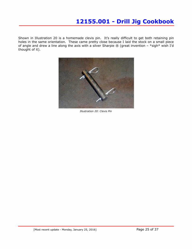
Shown in Illustration 20 is a homemade clevis pin. It’s really difficult to get both retaining pinholes in the same orientation. These came pretty close because I laid the stock on a small pieceof angle and drew a line along the axis with a silver Sharpie ® (great invention – *sigh* wish I’dthought of it).
[Most recent update - Monday, January 25, 2016] Page 25 of 37
Illustration 20: Clevis Pin

12155.001 - Drill Jig Cookbook
Appendix A10-Minute Weld Symbols Lesson
Illustration 21: Weld Symbol
[Most recent update - Monday, January 25, 2016] Page 26 of 37
(Opposite Arrow Side)
(Arrow Side)

12155.001 - Drill Jig Cookbook
Illustration 22: Weld "All Around" Symbol 1
Illustration 23: Weld "All Around" Symbol 2
Both the samples above get the same symbol. The circle means "WELD ALL AROUND" regardlessof the feature geometry.
[Most recent update - Monday, January 25, 2016] Page 27 of 37

12155.001 - Drill Jig Cookbook
Illustration 24: ANSI Recommended Welding Symbols
[Most recent update - Monday, January 25, 2016] Page 28 of 37

12155.001 - Drill Jig Cookbook
Appendix BTools You'll Need but May Not Have
Illustration 25: Automatic Punch
ENCO #505-0412Replacement Tip #240-2073
Illustration 26: Scriber
Scriber with Magnetic Pick-upENCO # 830-0382
Harbor Tools # 37151Northern Tools #143371
[Most recent update - Monday, January 25, 2016] Page 29 of 37
Illustration 27: Grinder

12155.001 - Drill Jig Cookbook
Illustration 28: Hobby Knife
MSC #06530927
Illustration 29: Cutoff/Band Saw
1-HP Horizontal Band Saw (Cutoff Saw)Harbor Tools #37151
Replacement 10 TPI Blade 522
[Most recent update - Monday, January 25, 2016] Page 30 of 37
12155.001 - Drill Jig Cookbook
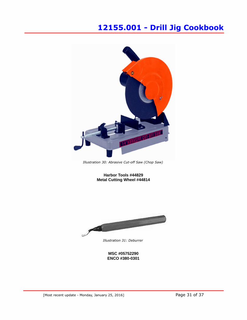
Illustration 30: Abrasive Cut-off Saw (Chop Saw)
Harbor Tools #44829Metal Cutting Wheel #44814
Illustration 31: Deburrer
MSC #05752290ENCO #380-0301
[Most recent update - Monday, January 25, 2016] Page 31 of 37

12154.001 - Drill Jig Cookbook
Appendix CList of Suppliers
The table on page 33 is a list of suppliers with whom I have dealt, their WEB address and my evaluation of the experience. I'm notendorsing any of these companies except to say that I've purchased from most of them, the items were pretty much as advertisedand were delivered (eventually in some cases). Some suppliers advertise low prices but when you order the item, they jack up theshipping charges ridiculously high and you wind up paying more than if you'd purchased from the other guy. Some claim to have nominimum charge but they tack on a massive handling charge if your order doesn’t meet their minimum (which they claim they don’thave). Some suppliers advertise periodic sales. A frugal person may consider visiting the supplier’s WEB sites periodically andwaiting for the item of interest to be offered at a reduced price. If you're one of those suppliers and you don't like what I've writtenabout you, don't waste your time or mine sending me a nasty-gram. Clean up you're act instead.1
1 I tried to obtain Home Depot and Lowe’s part numbers from their WEB pages but they both are so disorganized that it wasn’t worth the time. Grainger has better prices anyway.
[Most recent update - Monday, January 25, 2016] Page 32 of 37

12154.001 - Drill Jig Cookbook
SUPPLIER WEB ADDRESS PRICES SHIPPING COST DELIVERY TIME
MSC Industrial Supply mscdirect.com FraudulentFraudulent, they low-ball their
sell prices and thenovercharge for shipping.
Excellent
Northern Tools NorthernTool.com Good Too high Fair
ENCO use-enco.com Very Good Fair Fair
Harbor Freight Tools Harborfreight.com Good Good Terrible
Home Depot homedepot.com Good Good Poor
Grainger grainger.com Good Good Good
Surplus Center Surpluscenter.com Good Good Good
Table 1: List of Suppliers
[Most recent update - Monday, January 25, 2016] Page 33 of 37

12155.001 - Drill Jig Cookbook
Appendix BCommercial Parts:
MSC Part Number 06872139
[Most recent update - Monday, January 25, 2016] Page 34 of 37
Illustration 32: Swivel Head Thumb Screw

12155.001 - Drill Jig Cookbook
Illustration IndexIllustration 1: Finished Drilling Jig.........................................................................................1Illustration 2: 12154, Final Assembly Isometric......................................................................7Illustration 3: 12154A, Final Assembly [Optional Configuration]................................................8Illustration 4: 12154, Final Assembly BOM.............................................................................9Illustration 5: Final Assembly Dimensional Outline.................................................................10Illustration 6: 12154, Final Assembly Dimensional Outline [Optional Configuration]...................11Illustration 7: 12155, Retainer............................................................................................12Illustration 8: 12155, Retainer Isometric..............................................................................13Illustration 9: Harbor Freight Bender #44094.......................................................................13Illustration 10: 12266, Base...............................................................................................14Illustration 11: 12167, Support...........................................................................................15Illustration 12: 12167, Support Isometric & BOM..................................................................16Illustration 13: 12154, Final Assembly BOM [alternate configuration]......................................17Illustration 14: 12345, Horizontal Retainer Segment..............................................................18Illustration 15: 12154, Final Assembly Dimensional Outline [alternate configuration].................19Illustration 16: 12348, Support Angle..................................................................................21Illustration 17: Drill Jig Operation Instructions......................................................................23Illustration 18: More Drill Jig Operation Instructions..............................................................24Illustration 19: Still More Drill Jig Operation Instructions........................................................24Illustration 20: Clevis Pin...................................................................................................25Illustration 21: Weld Symbol...............................................................................................26Illustration 22: Weld "All Around" Symbol 1..........................................................................27Illustration 23: Weld "All Around" Symbol 2..........................................................................27Illustration 24: ANSI Recommended Welding Symbols...........................................................28Illustration 25: Automatic Punch.........................................................................................29Illustration 26: Scriber.......................................................................................................29Illustration 27: Grinder......................................................................................................29Illustration 28: Hobby Knife................................................................................................30Illustration 29: Cutoff/Band Saw.........................................................................................30Illustration 30: Abrasive Cut-off Saw (Chop Saw)..................................................................31Illustration 31: Deburrer....................................................................................................31Illustration 32: Swivel Head Thumb Screw ..........................................................................34
Index of TablesTable 1: List of Suppliers....................................................................................................33
[Most recent update - Monday, January 25, 2016] Page 35 of 37
12155.001 - Drill Jig Cookbook
Alphabetical Index12154...............................................................................................................................712154A..............................................................................................................................812154A, Final Assembly [Optional Configuration]....................................................................812155..............................................................................................................................1212167..............................................................................................................................1512345..............................................................................................................................1812348..............................................................................................................................2012666..............................................................................................................................14Abrasive Cut-off Saw...........................................................................................................6Abrasive Cut-off Saw (Chop Saw)........................................................................................31Angular Dimensioning..........................................................................................................4ANSI Recommended Welding Symbols.................................................................................28automatic punch.................................................................................................................5Automatic Punch...............................................................................................................29Axial Dimensioning..............................................................................................................3Base................................................................................................................................14center punch......................................................................................................................5Center Punch......................................................................................................................6Chop Saw..........................................................................................................................6Clamp...............................................................................................................................6Clevis Pin.........................................................................................................................25closed tubing ends..............................................................................................................4Closed Tubing Ends.............................................................................................................4Commercial Parts..............................................................................................................34corrode..............................................................................................................................4Cutoff/Band Saw...............................................................................................................30Deburrer..........................................................................................................................31Disclaimer..........................................................................................................................5Drawing Convention............................................................................................................3Drill Jig Operation Instructions............................................................................................23ENCO...................................................................................................................29, 31, 33Final Assembly...................................................................................................................7Final Assembly [Optional Configuration].................................................................................8Final Assembly BOM............................................................................................................9Final Assembly BOM [alternate configuration].......................................................................17Final Assembly Dimensional Outline.....................................................................................10Final Assembly Dimensional Outline [alternate configuration].................................................19Final Assembly Dimensional Outline [Optional Configuration]..................................................11Final Assembly Isometric.....................................................................................................7Finished Drilling Jig.............................................................................................................1Finishing the Project..........................................................................................................22Forward.............................................................................................................................3Grainger........................................................................................................................32p.Grinder........................................................................................................................6, 29Harbor Freight..........................................................................................................29p., 33Harbor Freight Bender #44094...........................................................................................13
[Most recent update - Monday, January 25, 2016] Page 36 of 37

12155.001 - Drill Jig Cookbook
Harbor Tools.....................................................................................................................31hobby knife........................................................................................................................5Hobby Knife......................................................................................................................30Home Depot..................................................................................................................32p.Horizontal Band Saw......................................................................................................6, 30Horizontal Retainer Segment..............................................................................................18Instructions for Use...........................................................................................................22Introduction.......................................................................................................................3list of suppliers.................................................................................................................32List of Suppliers.............................................................................................................32p.Materials of Construction.....................................................................................................4MIG...................................................................................................................................6More Drill Jig Operation Instructions....................................................................................24MSC........................................................................................................................30p., 33Northern Tools.............................................................................................................29, 33oxidizing............................................................................................................................4paint.................................................................................................................................4recommended tools.......................................................................................................4, 22Recommended Tools........................................................................................................4, 6Retainer...........................................................................................................................12Retainer Isometric.............................................................................................................13Safety Warnings.................................................................................................................5Scriber.............................................................................................................................29Square..............................................................................................................................6Still More Drill Jig Operation Instructions..............................................................................24straight edge......................................................................................................................5Support...........................................................................................................................15Support Angle...................................................................................................................20Support Isometric & BOM...................................................................................................16Surplus Center..................................................................................................................33Swivel Head Thumb Screw.................................................................................................34Templates..........................................................................................................................5TIG...................................................................................................................................6Tolerances..........................................................................................................................5Tools You'll Need but May Not Have.....................................................................................29WEB address....................................................................................................................32Weld "All Around" Symbol 1................................................................................................27Weld "All Around" Symbol 2................................................................................................27WELD ALL AROUND...........................................................................................................27Weld Symbols...................................................................................................................26Welding Symbols................................................................................................................4 .......................................................................................................................................8
[Most recent update - Monday, January 25, 2016] Page 37 of 37


![2-[2] B.Sc. Workshop Technology III Yr. Sem. V & VI184.171.241.213/~bamuacin/syllabus/2016_17/Science/12.pdf · indexing mechanism, Drill Jig — Types of drill bushes, ... P.H.Joshi](https://img.pdfslide.net/doc/110x75/5b0069b37f8b9af1148ca000/2-2-bsc-workshop-technology-iii-yr-sem-v-vi184171241213bamuacinsyllabus201617science12pdfindexing.jpg)